constant voltage dmx decoder
•
0 likes•52 views

DMX512 decoder PXL24-1-576 adopts the advanced micro-computer control technology and converted the DMX512/1990 digital signal widely used in international to the analog control signal. 1~24 channels output for option and each channel able to achieve 256 gradations of controling, and also it can be used as the connector of PC digital-light controller and analog light modulator. It is mainly used for the controlling of buildings & lights applied LED.

Recommended
Recommended
More Related Content
What's hot
What's hot (20)
Viewers also liked
Viewers also liked (13)
Similar to constant voltage dmx decoder
Similar to constant voltage dmx decoder (20)
Recently uploaded
Recently uploaded (10)
constant voltage dmx decoder
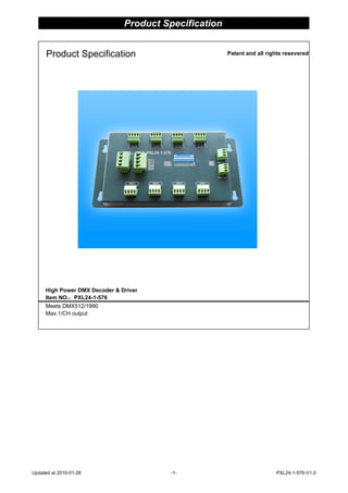
- 1. High Power DMX Decoder & Driver Item NO.:PXL24-1-576 Meets DMX512/1990 Max.1/CH output Patent and all rights reseveredProduct Specification Product Specification Updated at 2010-01-28 -1- PXL24-1-576-V1.0
- 2. DMX Decoder & Driver Series SUMMARIZE Thanks for your using PX series DMX512 decoder & driver. PX series adopt the advanced micro-computer control technology and converted the DMX512/1990 digital signal widely used in international to the analog control signal. 1~24 channels output for option and each channel able to achieve 256 gradations of contr- oling, and also it can be used as the connector of PC digital-light controller and analog light modulator. It is mainly used for the controlling of buildings & lights applied LED. Product Features ◆ Meets DMX512/1990 ◆ With 256 gradations and full-color contronl ◆ With 24 channels output and Max.1A/CH output ◆ Can achieve the asynchronous color changes effect under working with DMX controls system. ◆ With the light color selected mechanism, and be able to control the light with 1~3 colors ◆ Set the DMX address code freely ◆ With good noiseproof feature ◆ Custom-made Tech-parameter Decode CH. : 24 Channels Signal Input: DMX-512/1990 Standard digital signal Signal Output: 0~24V, Max.1A/CH. Power Supply: DC12-24V Power Dis.: 12V:<288W;24V<576W Power output: 12V:<288W;24V<576W Work Temp.: 0~70℃ … Size: L195(mm)*W100(mm)*H18(mm) Weight: 460g Dimension: PXL24-1-576 Updated at 2010-01-28 -2- PXL24-1-576-V1.0
- 3. DMX Decoder & Driver Series Internal Block Digram Appearance (1) Power IN (2) Power Out (3) Address setting interface (4) Driver output interface (4)DMX IN (5)DMX Out ◆Driver output interface Common in anode-V+ and with 8pcs of V+ interface & 24pcs of R,G,B output interface. Not only does it apply to the verious of LED module in full-color & monocolour , but also it can self-trimming the output current based on the load of LED module.1A per channel shall not beyond the maximum. Remark: Connect the anode and RGB wire of common anode RGB module to the output interface of deoder dire- ctly;Connect the anode wire of single-color module to V+ on decoder,and connect the cathode wire to one of RGB pin according to the LED's color; Connect several colors single-color module to one deco- der,please connect their anode wires to V+ pin on decoder. PXL24-1-576 1 2 3 4 5 Updated at 2010-01-28 -3- PXL24-1-576-V1.0
- 4. DMX Decoder & Driver Series Operating instruction PXL24-1-576 Decoder & Driver contolled by DMX512 controller,and its fore-end connect with the DMX512 signal transmit device. Take EC-DMX512 for example, its rear-end can connect with 0~24V circuit signal device. This instruction is only for LED driver. The connecting diagram is as following. Connecting of DMX-512 Signal Cable ◆ DMX signal cable used the CAT-3 cable,and DMX signal tells positive(+) from negative (-). While weld- ing the DMX signal cable plug,there must pay much attention to know postive(+) from negative(-), and then connect the DMX512 signal cable with the corresponding input interface of PXL24-1-576 correctly. ◆ Connect a signal terminal at the end of the whole connetion. PXL24-1-576 Updated at 2010-01-28 -4- PXL24-1-576-V1.0