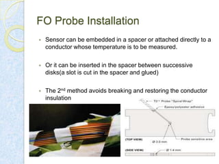
Fiber Optic Sensors for
Transformers
Guided by: Mrs. Amruta Deshpande
Contents:


Introduction



Negligence of FO Sensors



Advantages of FO Sensors



Recent development to measure Hot spot temperature.



Construction.



Operating Principle.



FO Probe Installation.
Introduction:


Transformer loading capacity is limited by winding
temperature which is not uniform.



Winding Hotspot temperature.



Conventional methods for measurement.



Assumptions in conventional methods.
Negligence of FO Sensor:


Fragile- High percentage of fiber failures due to breakage in
industry.



Cost- high initial cost compared to a conventional product
Advantages of FO Sensors:


Reliable and do not cause delay during emergency
overloading.



Require less maintenance.
Recent Development:


Robust fiber optic sensors have been constructed.



FO probe- 200 micron optical fiber with a permeable
protective PTFE sheath.



Based on GaAs technology
Operating Principle of FO Sensor


Based on variation in absorption spectrum of GaAs with
respect to temperature



White light is incident on the crystal.



Depending on temperature light is more or less absorbed and
the less is reflected by a mirror.



Reflected light is analyzed electronically.
Typical specifications/Characteristics:













Temperature range: −40°C to 225°C
Resolution: 0.1°C
Accuracy : 2°C
Available sensor length: 1 to 15 meters
Fiber type: 200 μm silica fiber
Cable sheathing: Double PTFE sheathing (spiral wrap)
Sensor dimensions: 1.5 mm O.D.
resilient construction.
resistance to chemicals
completely immune to EMI and RFI environments
FO Probe Installation


Sensor can be embedded in a spacer or attached directly to a
conductor whose temperature is to be measured.



Or it can be inserted in the spacer between successive
disks(a slot is cut in the spacer and glued)



The 2nd method avoids breaking and restoring the conductor
insulation
Installation continued…


Installation of FO Probe and its handling during
manufacturing are challenging to avoid sharp bends.



This may break the fiber.



An improvement is a simplified through-wall connection.
This optical feed has a simple design, provides low loss optical
Connection and leak free operation. With this, survival rate of
FO sensors is better than 90%.
Practical installation:
Conclusion:


Hot spot measurement with fiber optic sensors is now being
accepted by many utilities and there are some drastic
improvements in their design and construction.



It is most likely fiber optic sensors will be used for transformer
cooling, loading etc., considering less maintenance, fast
response and accuracy.
Future Scope:


With more and more development in FO technology, cost of
FO temperature monitoring systems can be fraction of 1% of
the cost associated with power transformer.



Long term benefits can be achieved.
References:







Nasser a. Al-Qahtany*, Krishnan s. Balasubramanian, “Optic
Fiber Sensors for transformer winding hot-spot measurement
- Saudi electricity company specification” national grid SA –
Saudi electricity company, standards & specifications
department.
Sheldon p. Kennedy, Thomas Gordner, “Hot spot studies for
sheet wound transformer windings” Doble engineering
company – 80th international conference of Doble clients.
Tpt-32 temperature sensor for oil-filled Transformers-PDF
Andersen, O.W. “Finite element solution of skin effect and
eddy current problems” IEEE paper A77 616-6, Mexico
City, July 1977

Fiber optic sensors for transformers

  • 1.
    Fiber Optic Sensorsfor Transformers Guided by: Mrs. Amruta Deshpande
  • 2.
    Contents:  Introduction  Negligence of FOSensors  Advantages of FO Sensors  Recent development to measure Hot spot temperature.  Construction.  Operating Principle.  FO Probe Installation.
  • 3.
    Introduction:  Transformer loading capacityis limited by winding temperature which is not uniform.  Winding Hotspot temperature.  Conventional methods for measurement.  Assumptions in conventional methods.
  • 4.
    Negligence of FOSensor:  Fragile- High percentage of fiber failures due to breakage in industry.  Cost- high initial cost compared to a conventional product
  • 5.
    Advantages of FOSensors:  Reliable and do not cause delay during emergency overloading.  Require less maintenance.
  • 6.
    Recent Development:  Robust fiberoptic sensors have been constructed.  FO probe- 200 micron optical fiber with a permeable protective PTFE sheath.  Based on GaAs technology
  • 8.
    Operating Principle ofFO Sensor  Based on variation in absorption spectrum of GaAs with respect to temperature  White light is incident on the crystal.  Depending on temperature light is more or less absorbed and the less is reflected by a mirror.  Reflected light is analyzed electronically.
  • 10.
    Typical specifications/Characteristics:           Temperature range:−40°C to 225°C Resolution: 0.1°C Accuracy : 2°C Available sensor length: 1 to 15 meters Fiber type: 200 μm silica fiber Cable sheathing: Double PTFE sheathing (spiral wrap) Sensor dimensions: 1.5 mm O.D. resilient construction. resistance to chemicals completely immune to EMI and RFI environments
  • 11.
    FO Probe Installation  Sensorcan be embedded in a spacer or attached directly to a conductor whose temperature is to be measured.  Or it can be inserted in the spacer between successive disks(a slot is cut in the spacer and glued)  The 2nd method avoids breaking and restoring the conductor insulation
  • 12.
    Installation continued…  Installation ofFO Probe and its handling during manufacturing are challenging to avoid sharp bends.  This may break the fiber.  An improvement is a simplified through-wall connection.
  • 13.
    This optical feedhas a simple design, provides low loss optical Connection and leak free operation. With this, survival rate of FO sensors is better than 90%.
  • 14.
  • 15.
    Conclusion:  Hot spot measurementwith fiber optic sensors is now being accepted by many utilities and there are some drastic improvements in their design and construction.  It is most likely fiber optic sensors will be used for transformer cooling, loading etc., considering less maintenance, fast response and accuracy.
  • 16.
    Future Scope:  With moreand more development in FO technology, cost of FO temperature monitoring systems can be fraction of 1% of the cost associated with power transformer.  Long term benefits can be achieved.
  • 17.
    References:     Nasser a. Al-Qahtany*,Krishnan s. Balasubramanian, “Optic Fiber Sensors for transformer winding hot-spot measurement - Saudi electricity company specification” national grid SA – Saudi electricity company, standards & specifications department. Sheldon p. Kennedy, Thomas Gordner, “Hot spot studies for sheet wound transformer windings” Doble engineering company – 80th international conference of Doble clients. Tpt-32 temperature sensor for oil-filled Transformers-PDF Andersen, O.W. “Finite element solution of skin effect and eddy current problems” IEEE paper A77 616-6, Mexico City, July 1977