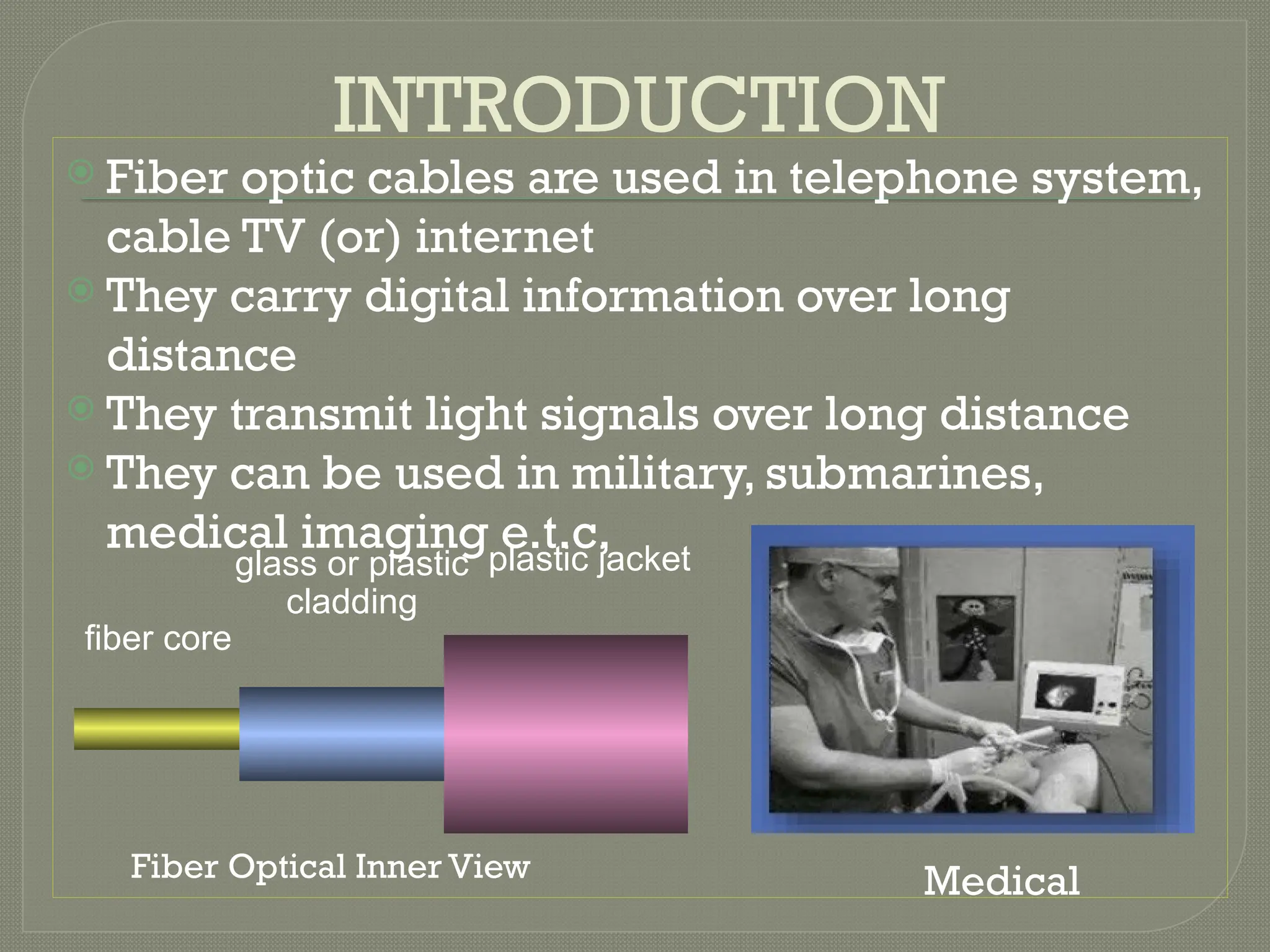
INTRODUCTION
Fiber opticcables are used in telephone system,
cable TV (or) internet
They carry digital information over long
distance
They transmit light signals over long distance
They can be used in military, submarines,
medical imaging e.t.c,
plastic jacket
glass or plastic
cladding
fiber core
Medical
Fiber Optical Inner View
4.
Working Principle ofTIR
when a ray light travels from a denser to a rare medium such that the angle of incidence is greater than critical angle the ray reflects back in to the
same medium this phenomena is TIR
In optical fiber the ray undergo repeated total number of reflections until it emerges out of the other end of fiber ,even if fiber is bent.
military Electronics
5.
Basic communication system
Transmitter:In this message is generated
an put in suitable form
Information channel: It is divided in two
categories (i)unguided(ii)guided
Receiver:The message is extracted from
the channel and put in final form.
Transmitter
Information
channel
receiver
6.
Block diagram
MessageOrigin: it is a transducer to convert
electrical message in to proper format.
Modulator: it perform two functions(i) convert
electrical message to proper format(ii)it
impress the signal wave generated by source
Carrier Oscillator: carrier wave produced by
electronic oscillator for fiber system i.e.
LD,LED.
7.
Channel Coupler: Inradio/TV it acts
like an antenna.
Information Channel: It is a path
between transmitter and receiver. It is
used to boost up the power level of
weak signal.
Detector: In this optic wave convert in
to electric current by photodiode.
Signal Processing: In this two types of
circuits are used (i)Amplifier (ii)Filter
Applications
Telephone applicationsare wide spread ranging from
global n/w to desktop computer
It involves transmission of voice ,data (or) video over
distances of less than a meter tom 100km.
POTS(Plain old telephone service) across nation wide
network
LECS(Local exchange carries) central office switches
at local levels
In cable TV companies also used fiber for delivery of
digital video(or) data services.
It used in Bio-medical industry, Modern tele- medicine
for transmission of digital diagnostic images.
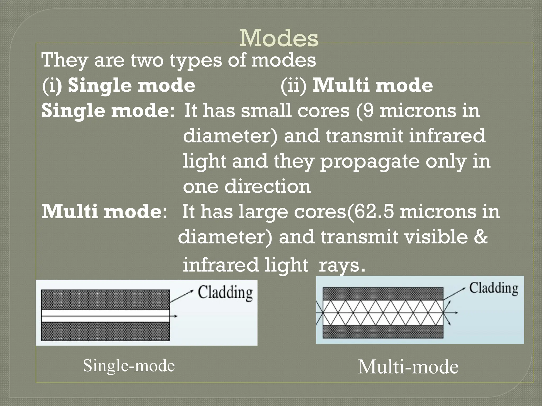
10.
They are twotypes of modes
(i) Single mode (ii) Multi mode
Single mode: It has small cores (9 microns in
diameter) and transmit infrared
light and they propagate only in
one direction
Multi mode: It has large cores(62.5 microns in
diameter) and transmit visible &
infrared light rays.
Modes
Single-mode Multi-mode
11.
Optical Fiber WaveGuides
Step Index:The rays entering at different angles travel
different paths and emerge out at the end of fiber at
different times
GRIN :The core has non uniform refractive index in any
medium
Materials :
Glass core-Glass cladding
Plastic core-Plastic cladding
The size of fiber denoted by writing a core diameter that
cladding diameter both in microns with a slash between them
50/125.
Glass-long distance, Plastic-Short distance
12.
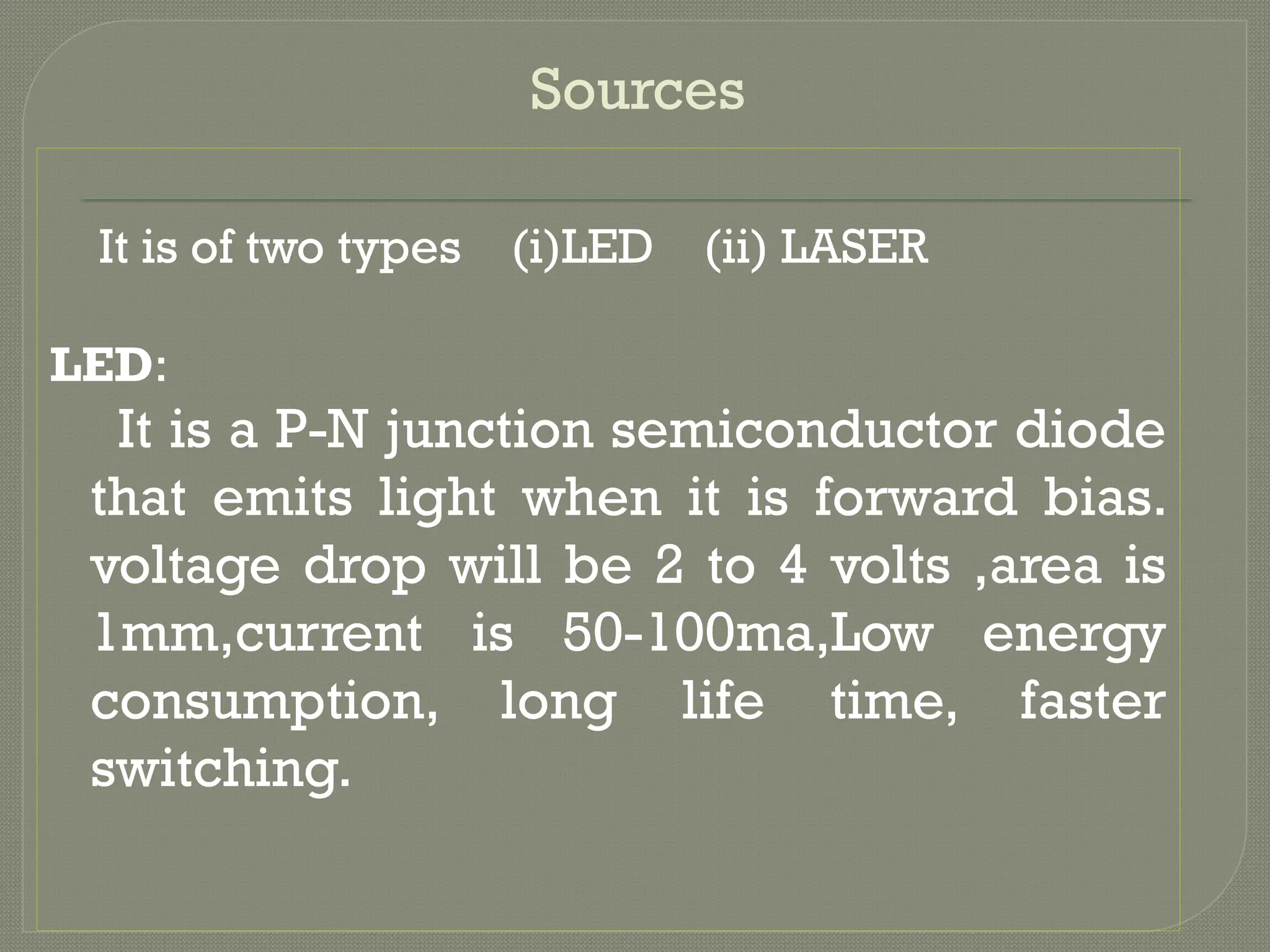
Sources
It is oftwo types (i)LED (ii) LASER
LED:
It is a P-N junction semiconductor diode
that emits light when it is forward bias.
voltage drop will be 2 to 4 volts ,area is
1mm,current is 50-100ma,Low energy
consumption, long life time, faster
switching.
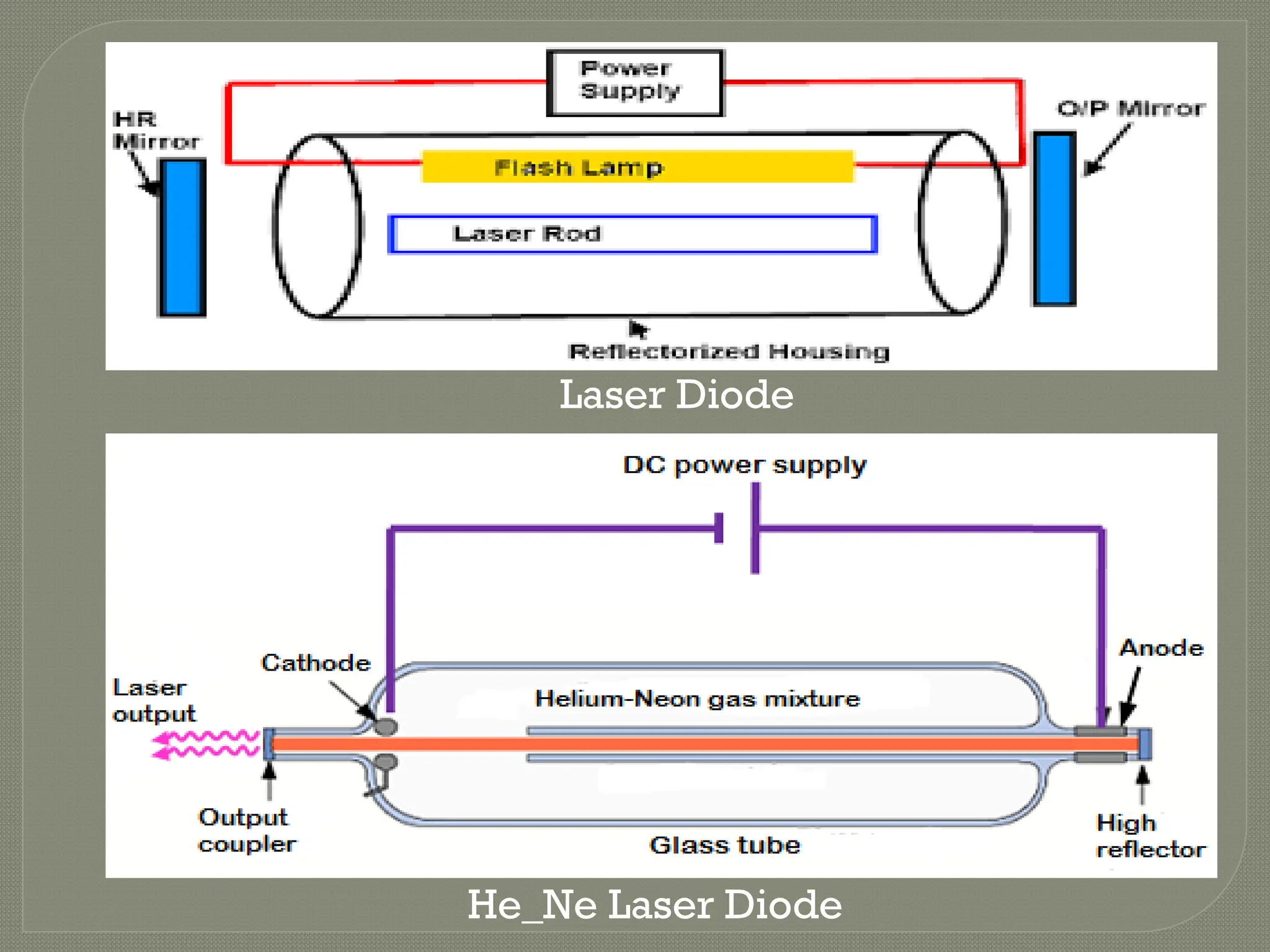
LASER
In this twotypes (i)He-Ne (ii)Nd:YAG
He-Ne: It is coupled to bare fiber to detect
break/cut and by using this NA can be measured.
In this two types of emissions
(i)Spontaneous:-Electrons drops from an excited
state to a lower state emitting a photon
(ii)Stimulated:-Photon of same frequency
interacts with electron in excited state which
drops two lower state.
Duration 10-8
seconds the atom stay in high state.
11 years in room temperature,&700
-10,000hours.
PHOTO DETECTORS
In thisphoto detection mechanism are of
two types
External:- In which electrons are feed
from the surface of a metal by the energy
absorbed from an incident stream of
photons. EX:Vacuum tube, PMT
Internal:- The free charge carries
electrons and holes are generated by
absorption of incoming photons. Ex:
PN,PIN,APD
17.
Semi conductor:-
They aresmall, light ,sensitive, fast and operate with a
few bias volts
For Emission the diode is forward bias the charges
injected in the junction recombination to produce
photons
For detection the diode reverse bias to generate
electron hole pair producing electric current.
PIN: High resistance ,improve efficiency
APD: It convert light to electricity, High reverse bias,
Reverse voltage 100-200v,gain 105
-106
Losses in Fiber
Attenuation:
Lossof light energy as the light pulse
travels from one end of cable to the
other.-signal loss(or)fiber loss
It also decide no. of repeaters required
between transmitter and receiver.
It directly proportional to length of cable.
Bending
Macroscopic: inwhich fiber undergo bends which
causes certain modes not be reflected.
Microscopic: Either core (or) cladding undergo slight
bends at it’s surface.
Inter modal: Difference between modes with in
multimode
Intra modal: Pulse spreading that occurs in single mode
Light energy due to heating of ion impurities results in
dimming of light at the end of fiber
(i)Intrinsic(ii)Extrinsic
Distortion
Absorption
22.
Measurements
Attenuation-cut back technique,OTDR
Numerical aperture measurement
(i)Scanning photo detector
(ii)Vibration isolated granite slab
Time division multiplexing
Frequency division multiplexing
Measurement losses in splice and
connector
Inter-ferometric method
Outer diameter by shadow method