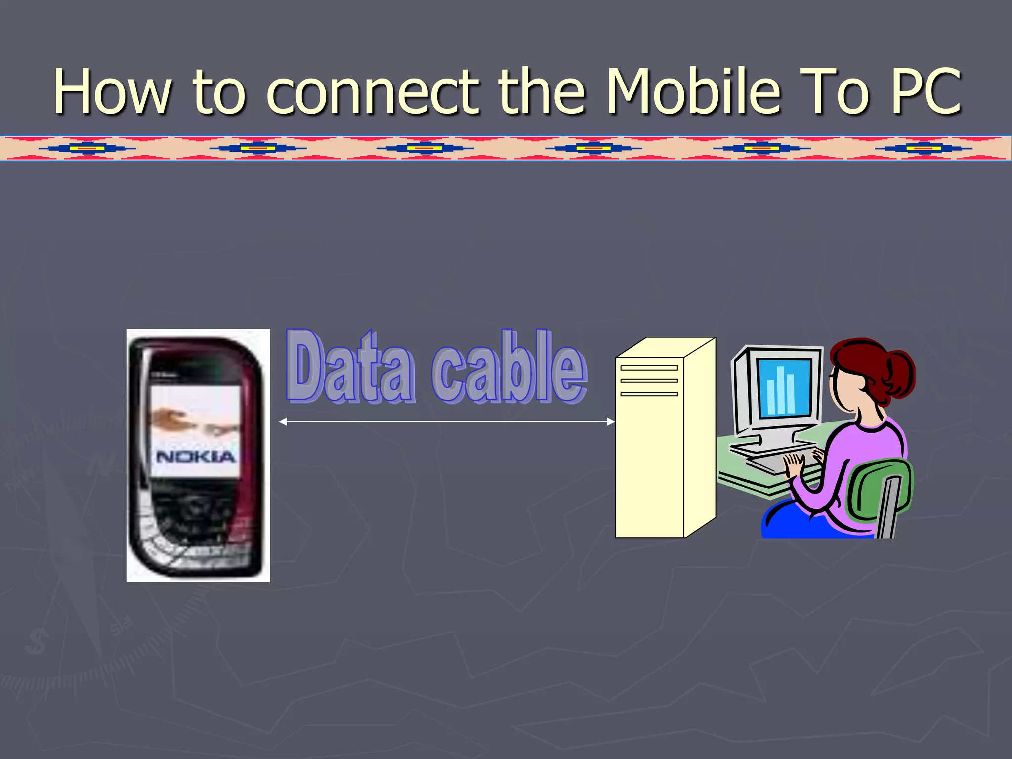
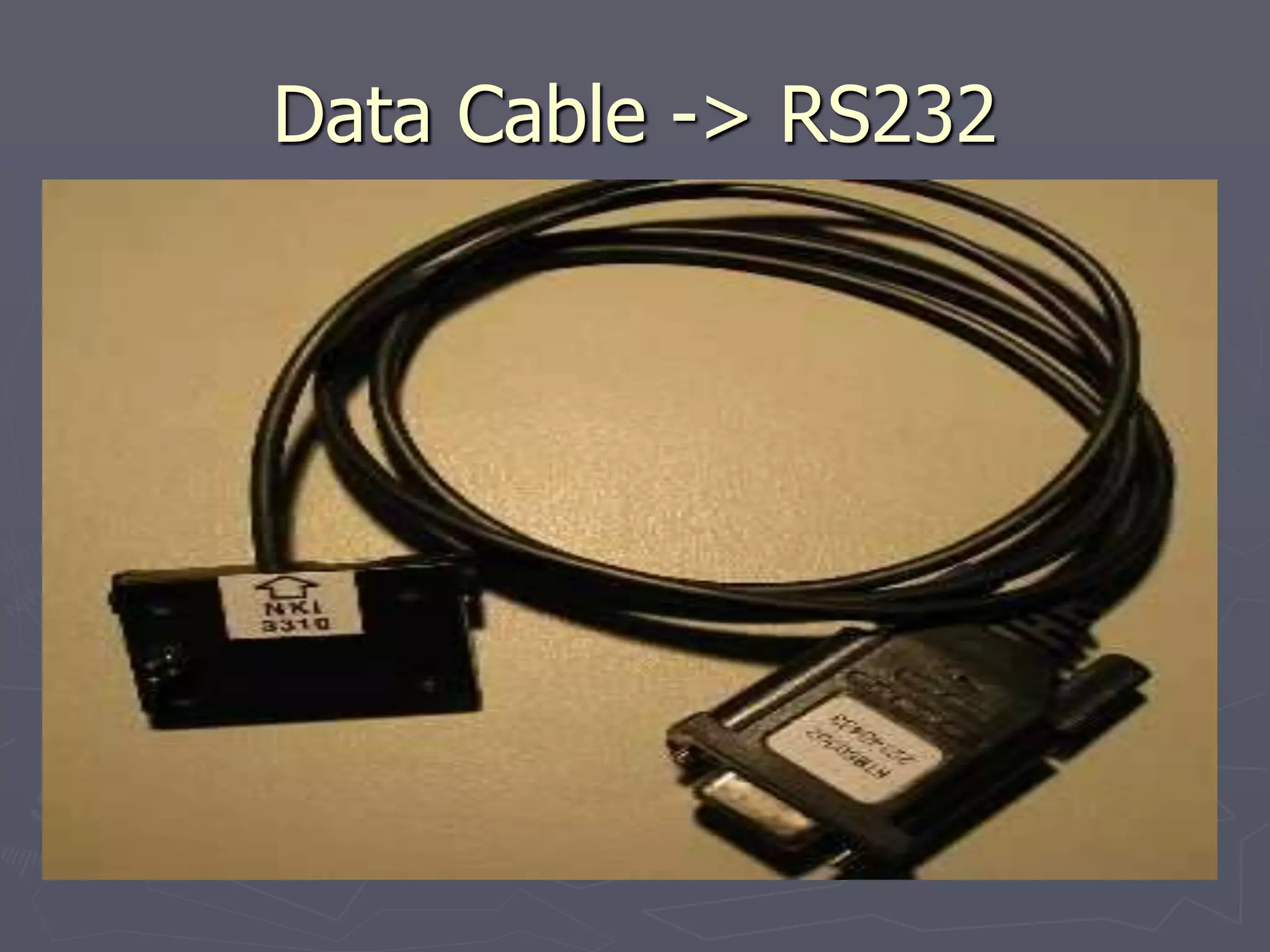
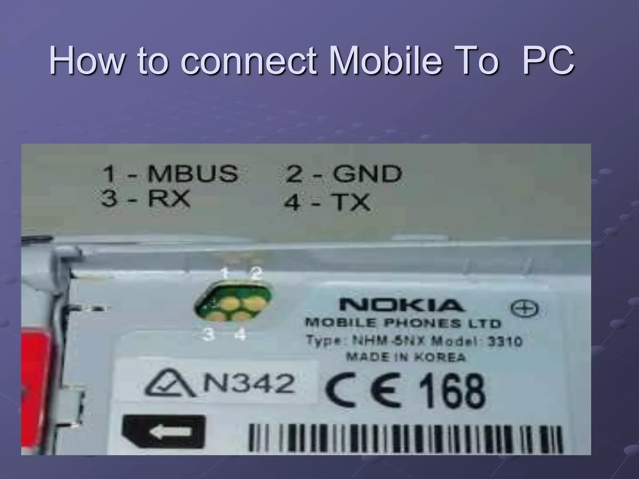
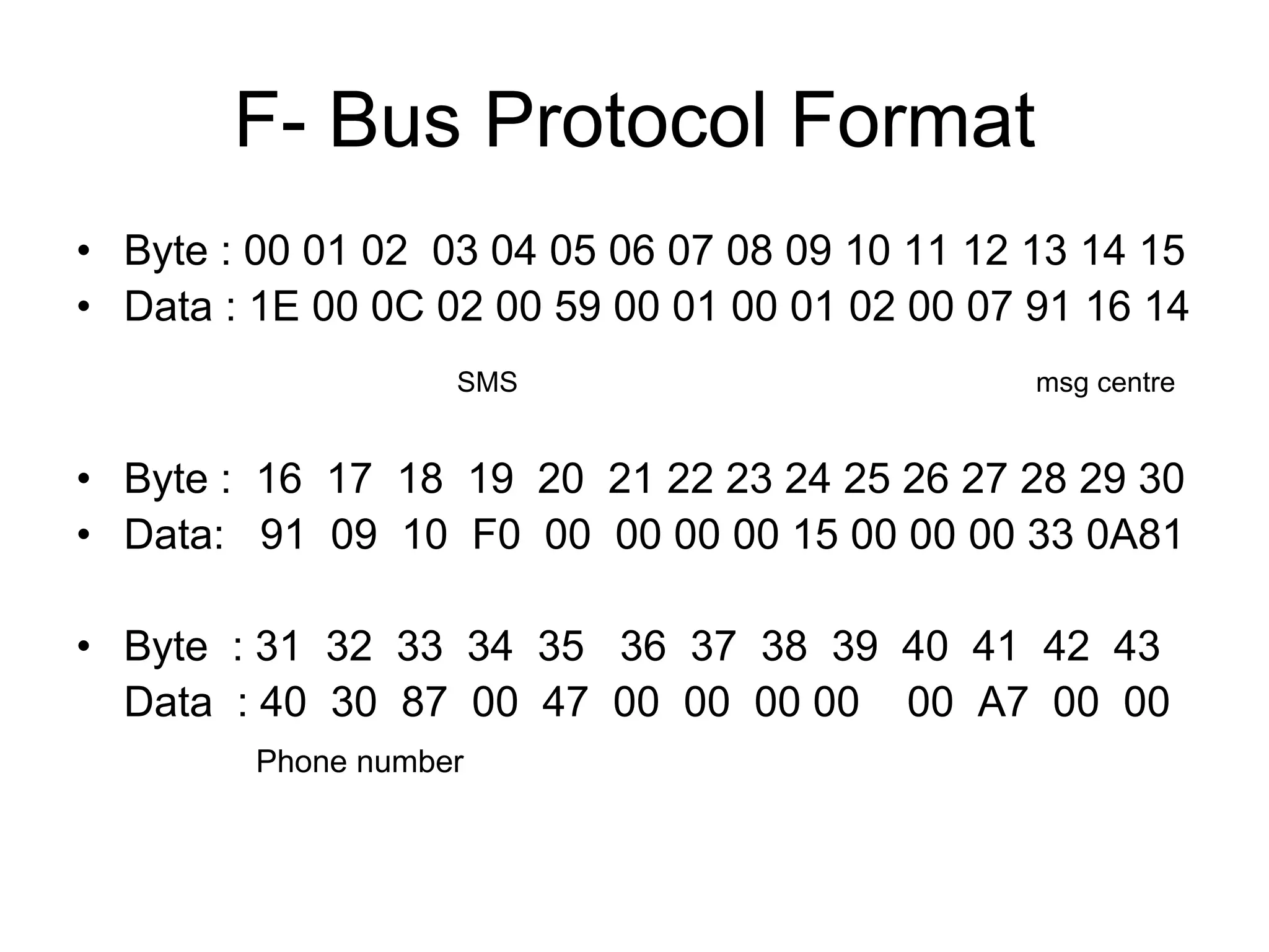
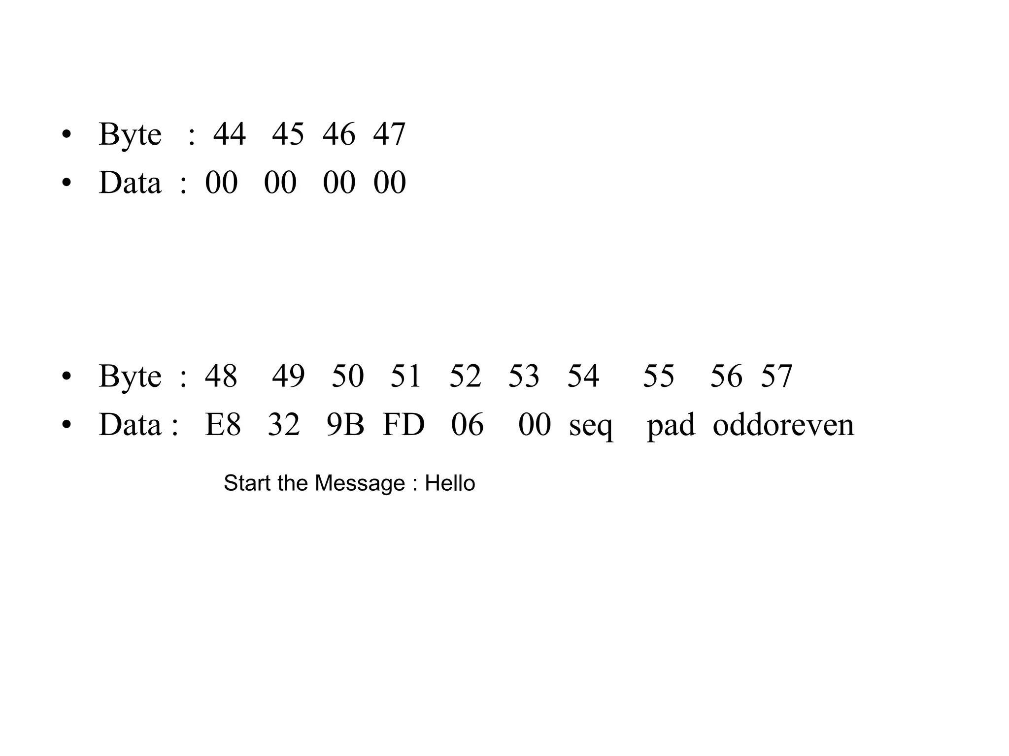
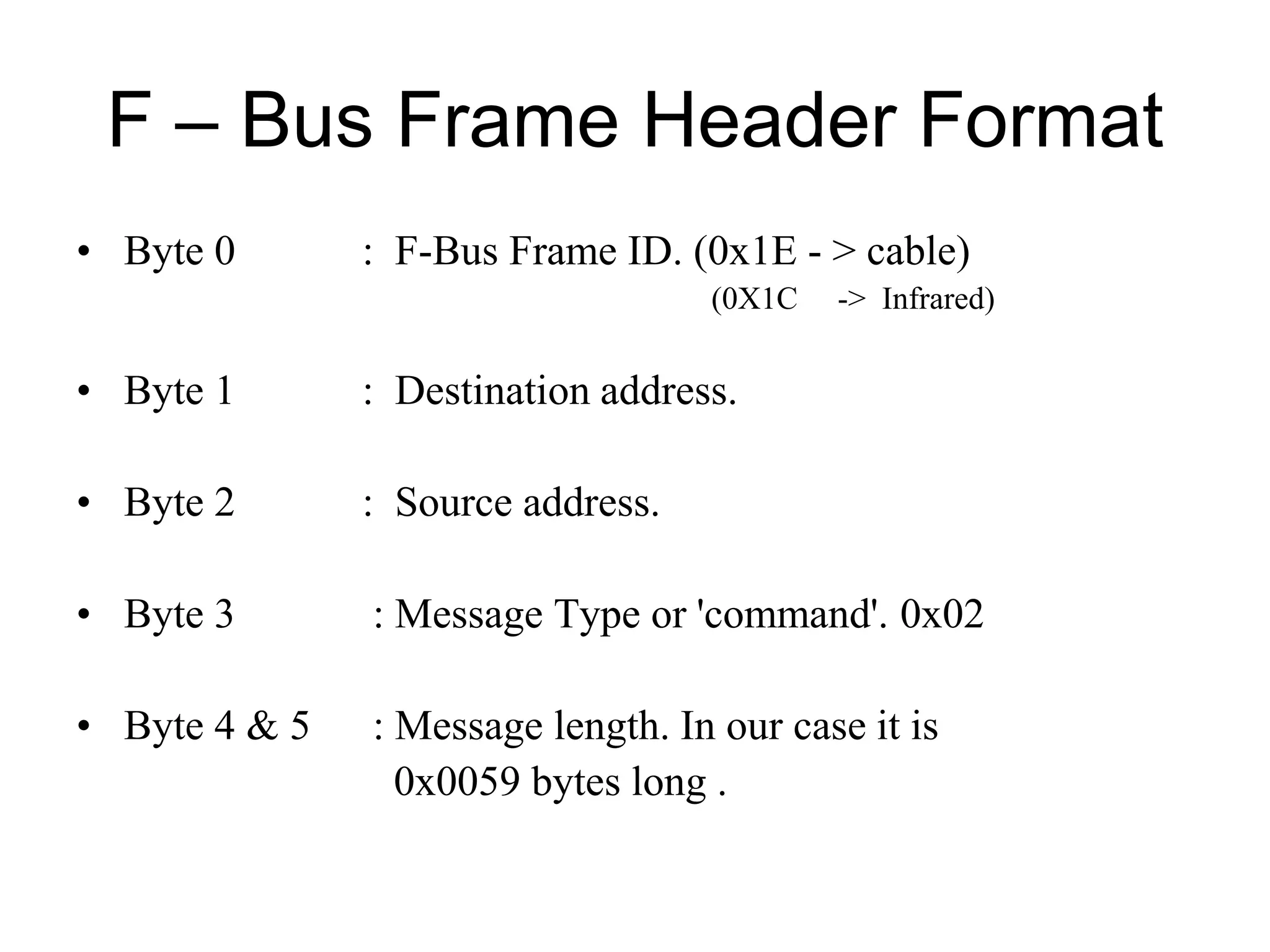
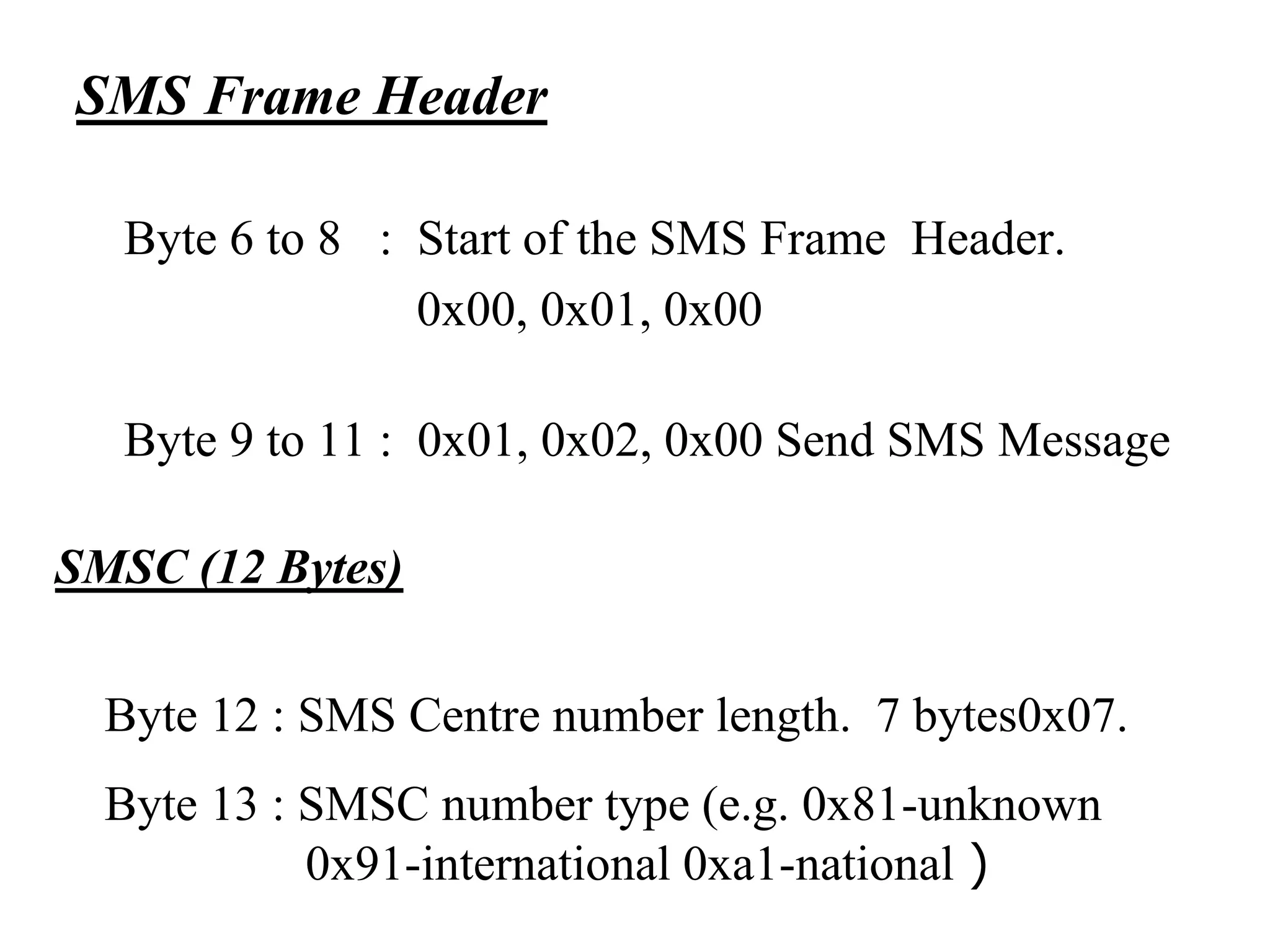
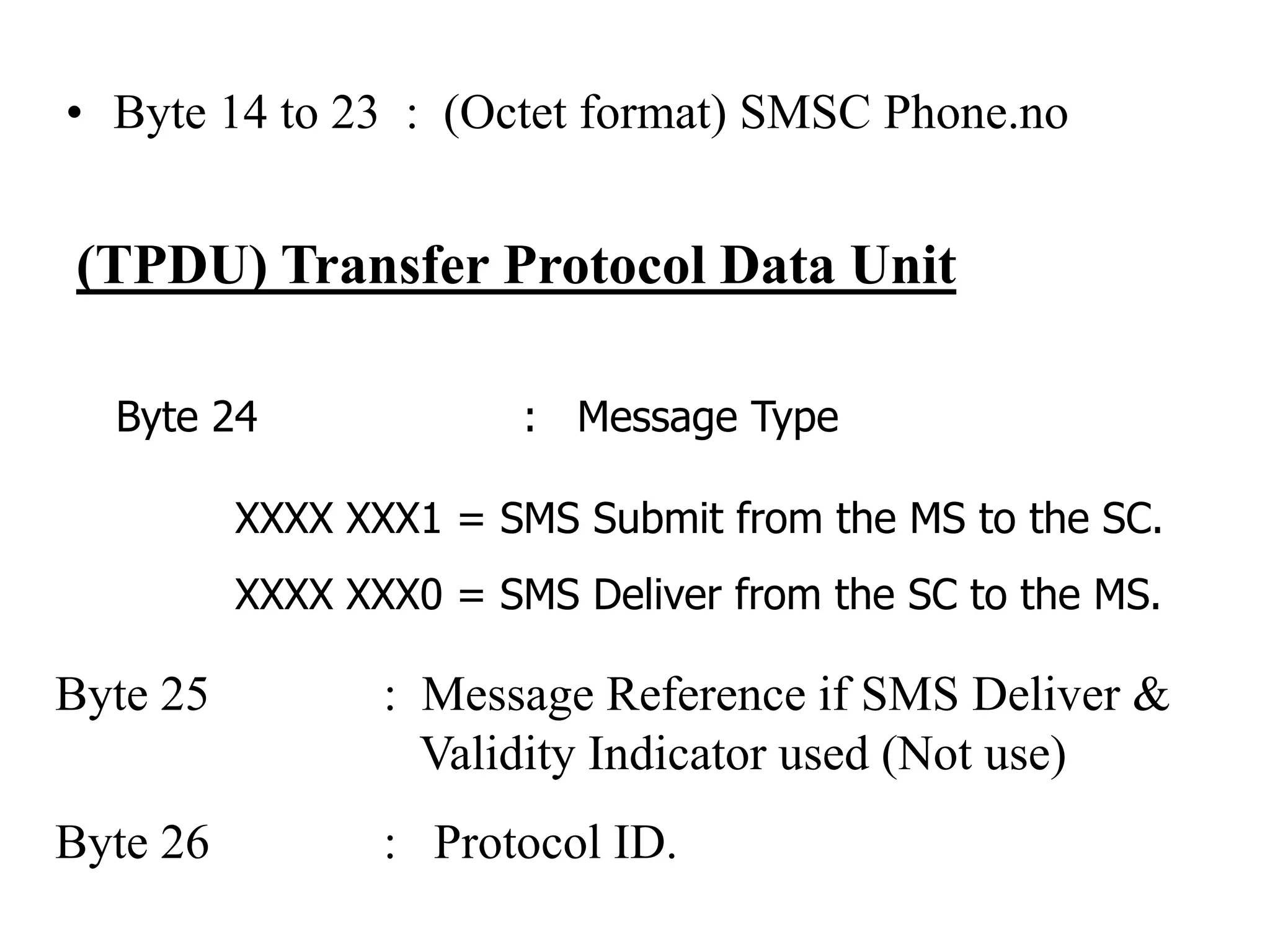
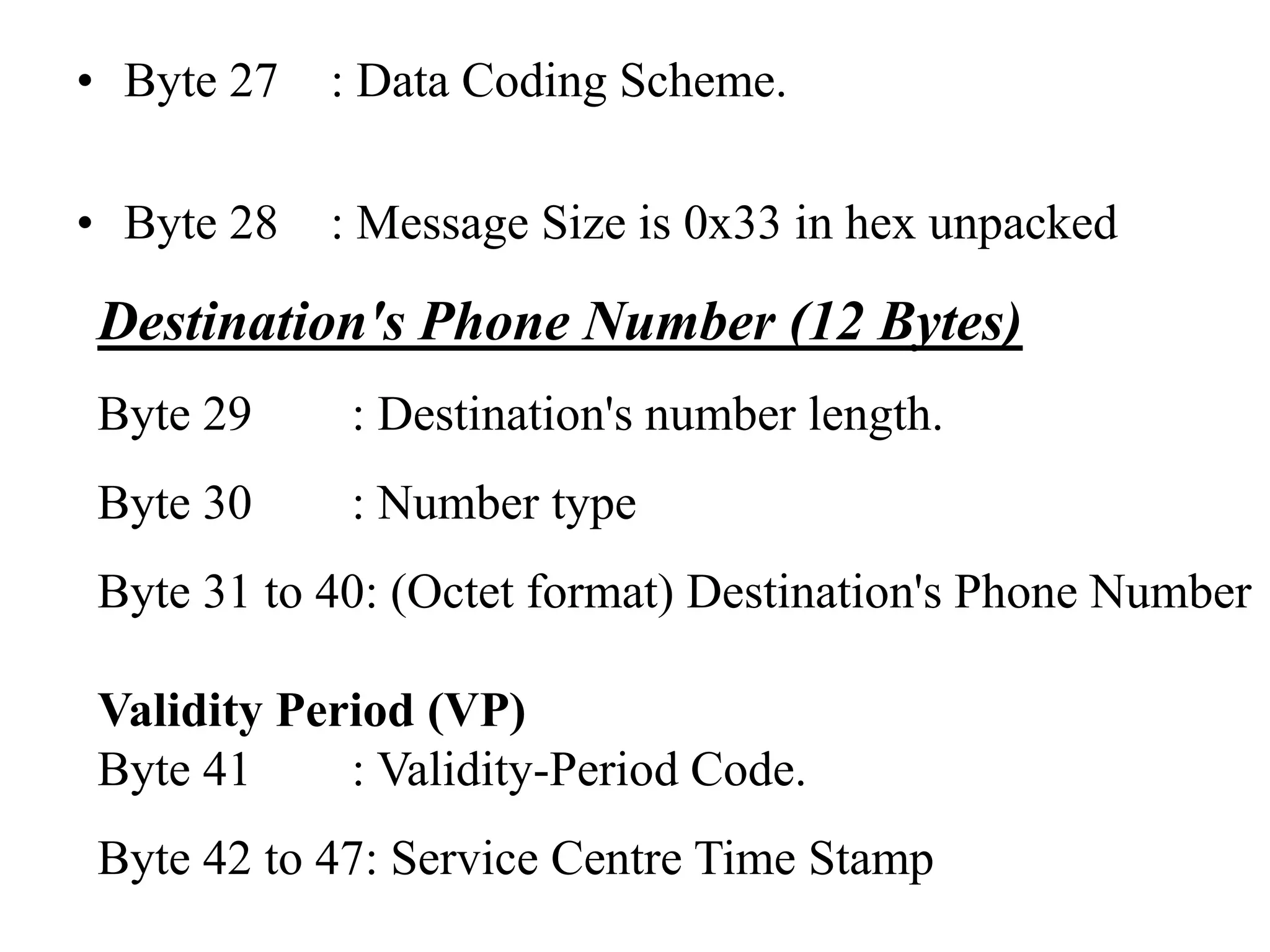
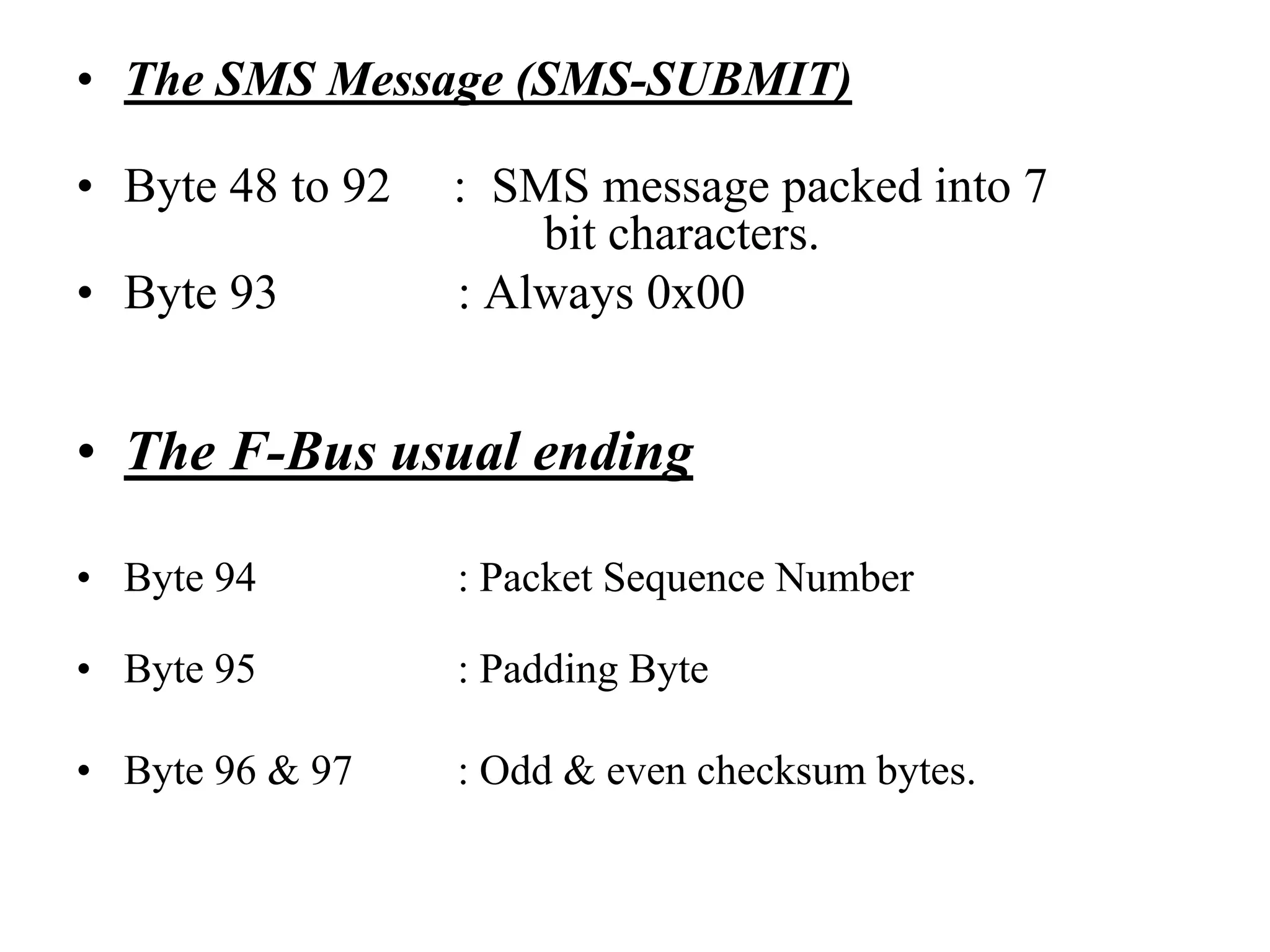
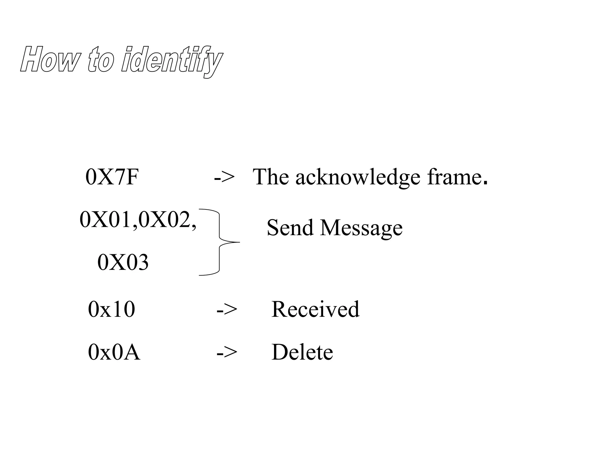
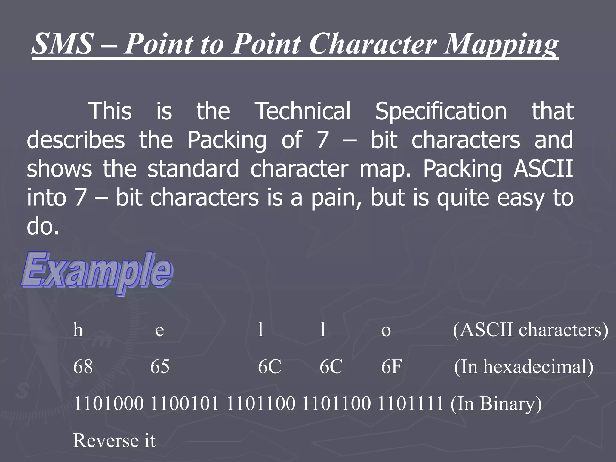
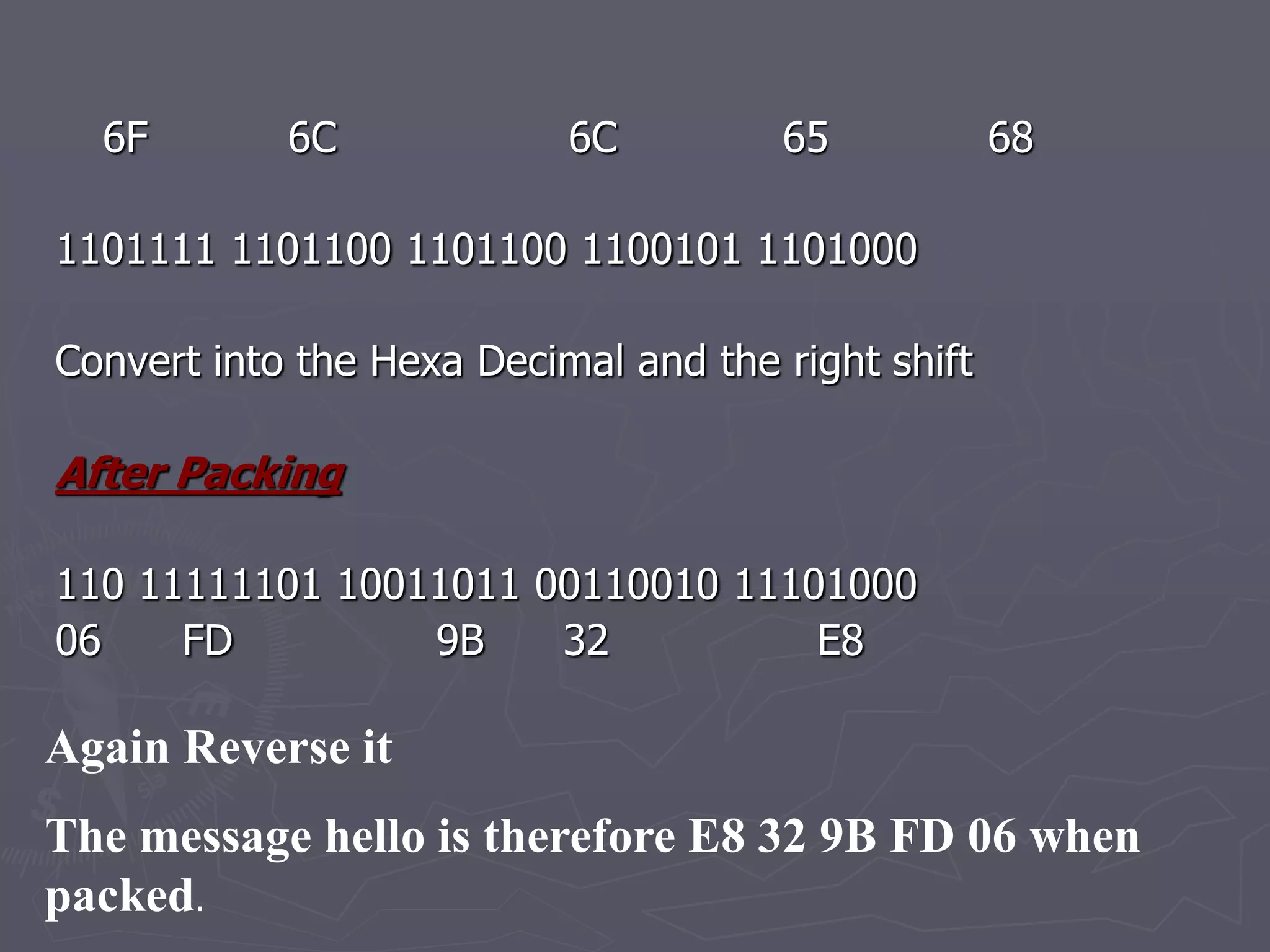
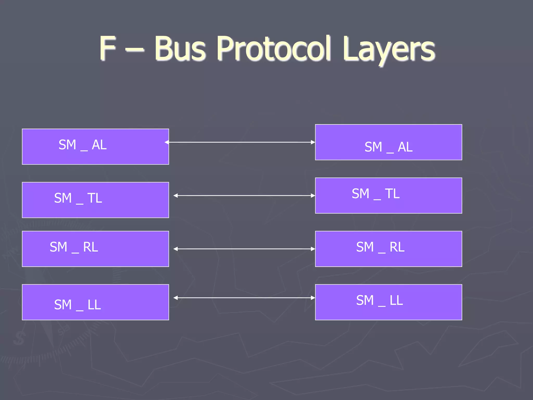
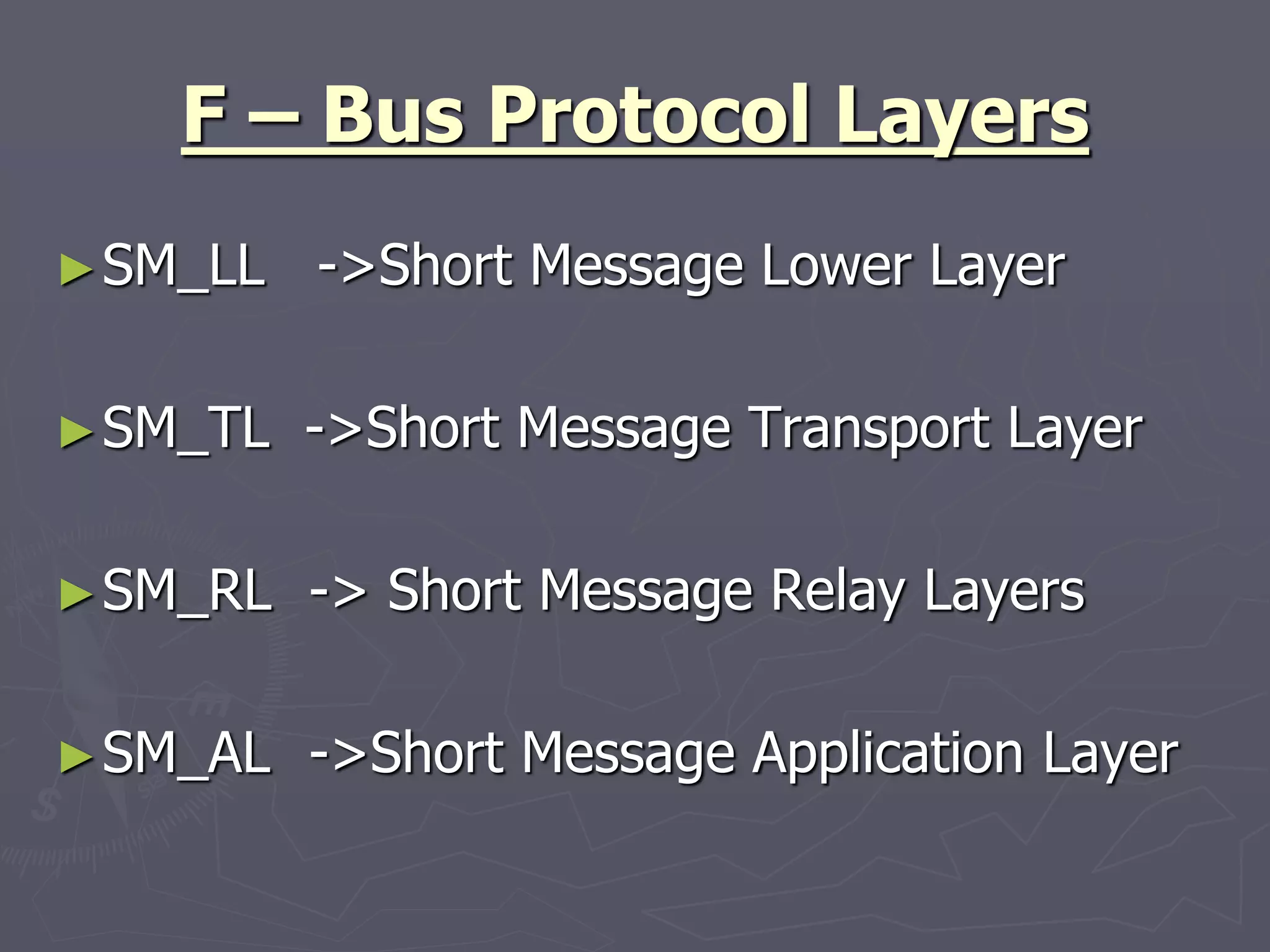
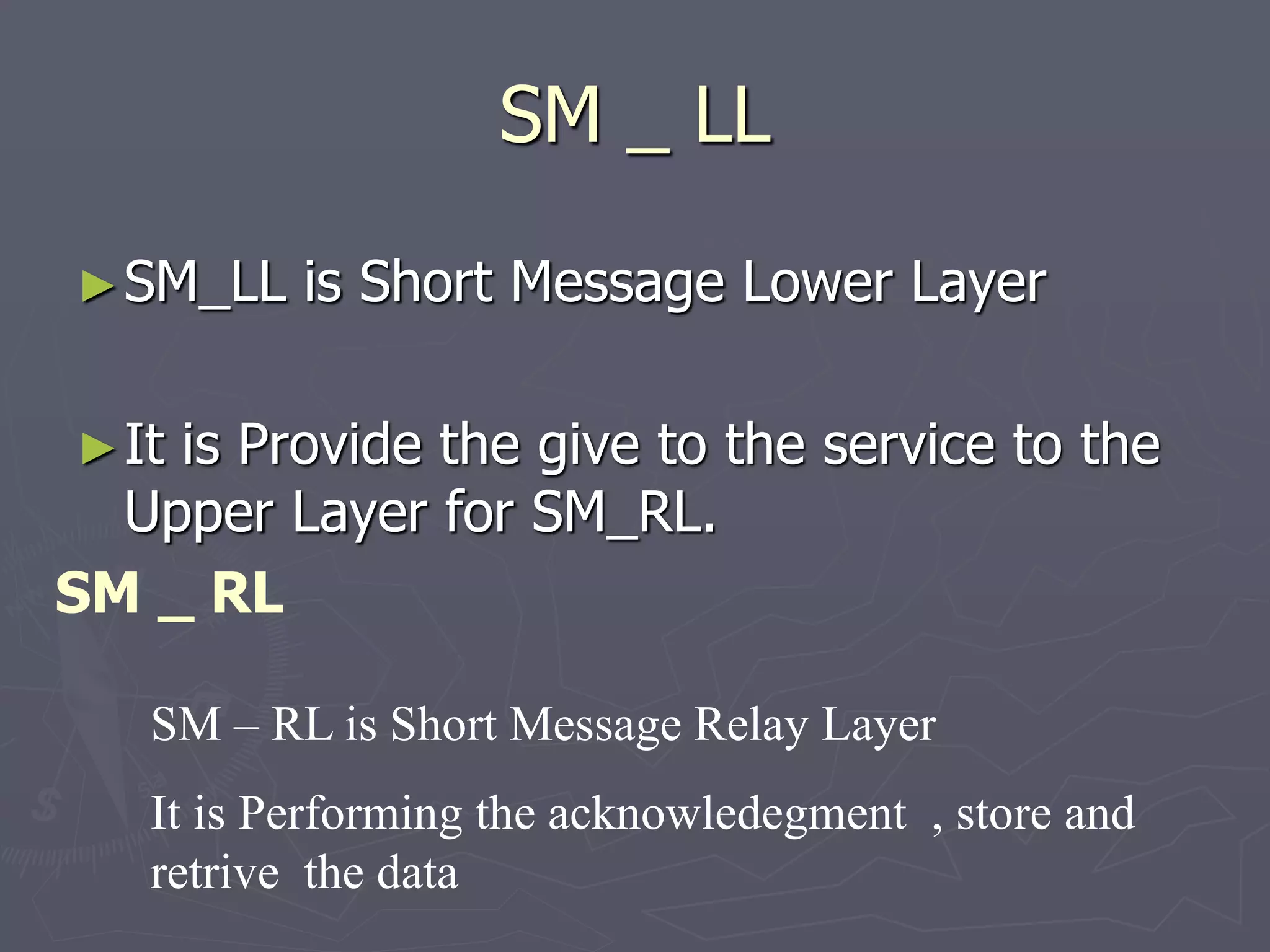
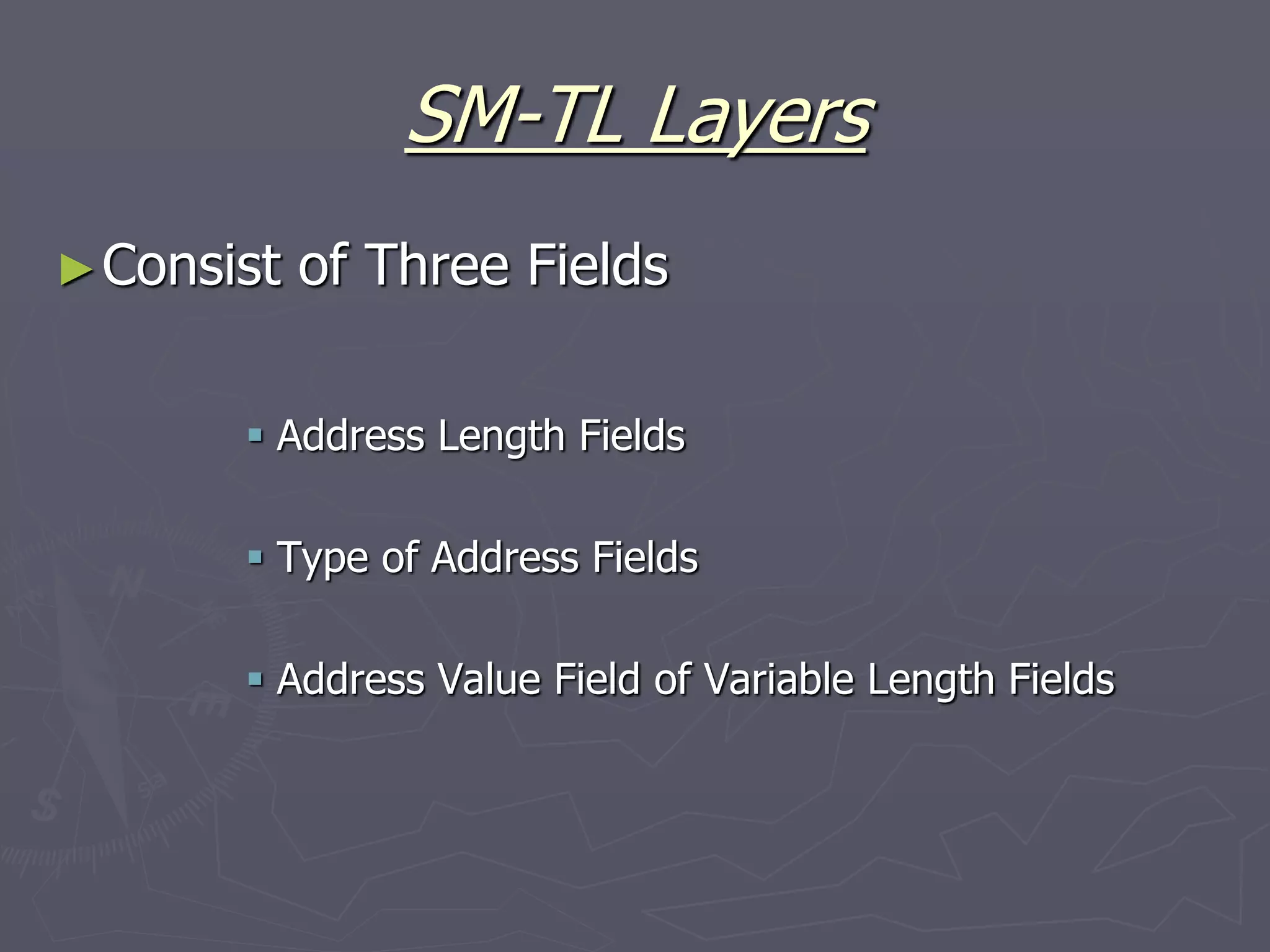
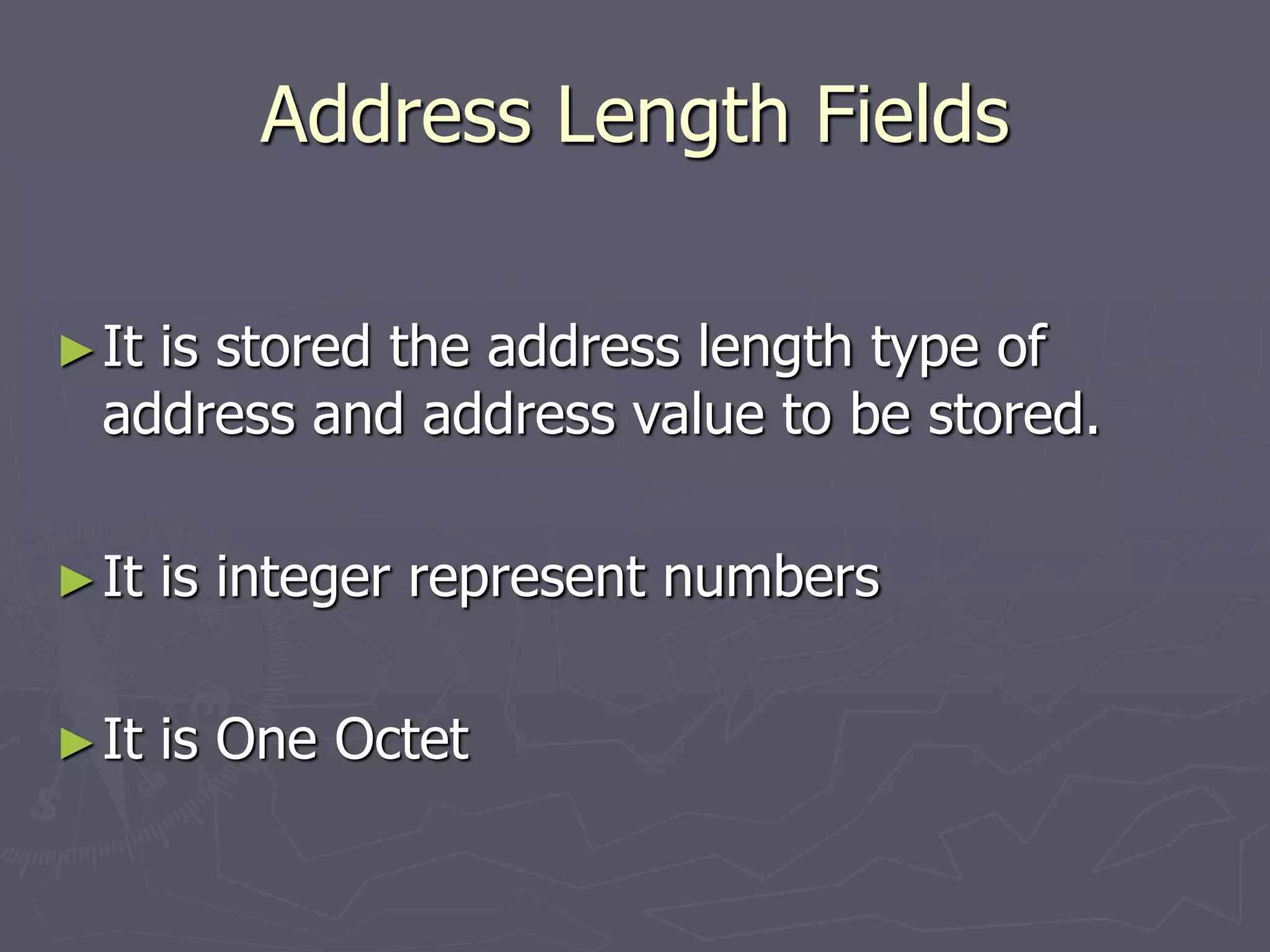
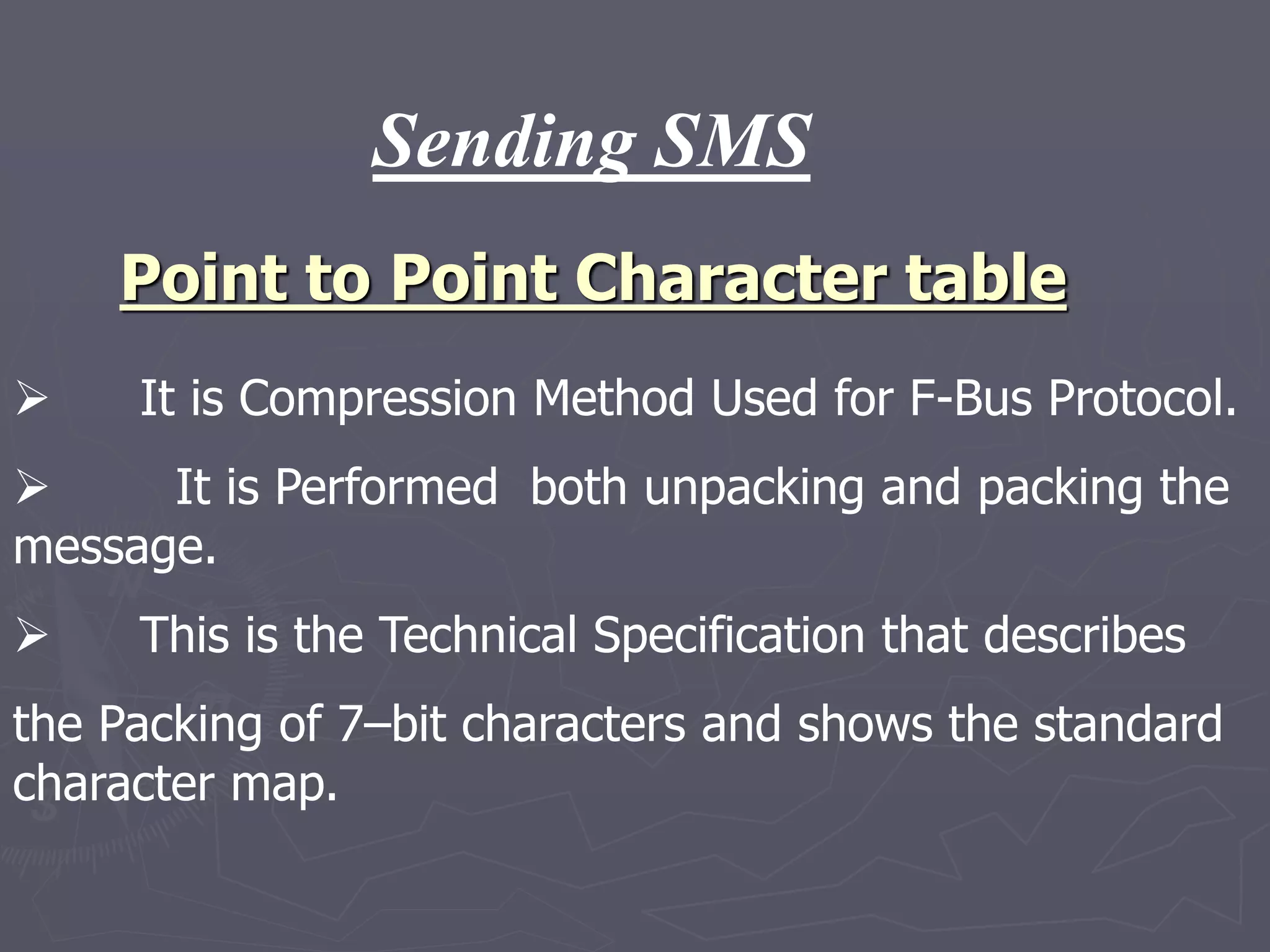
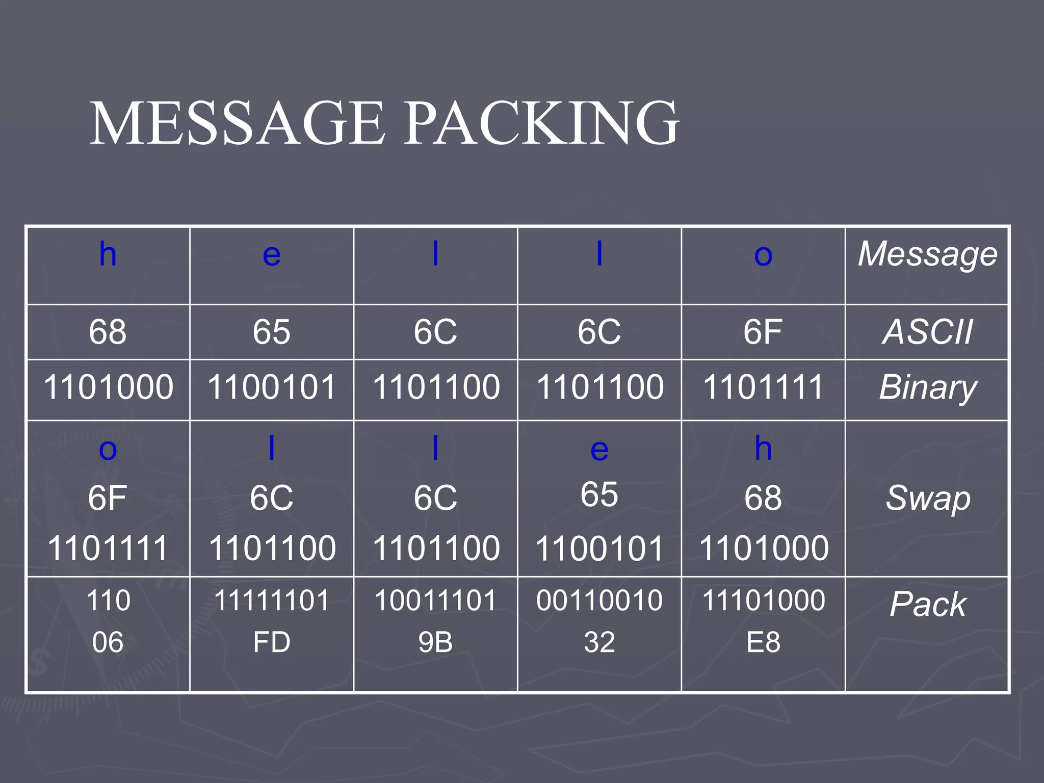
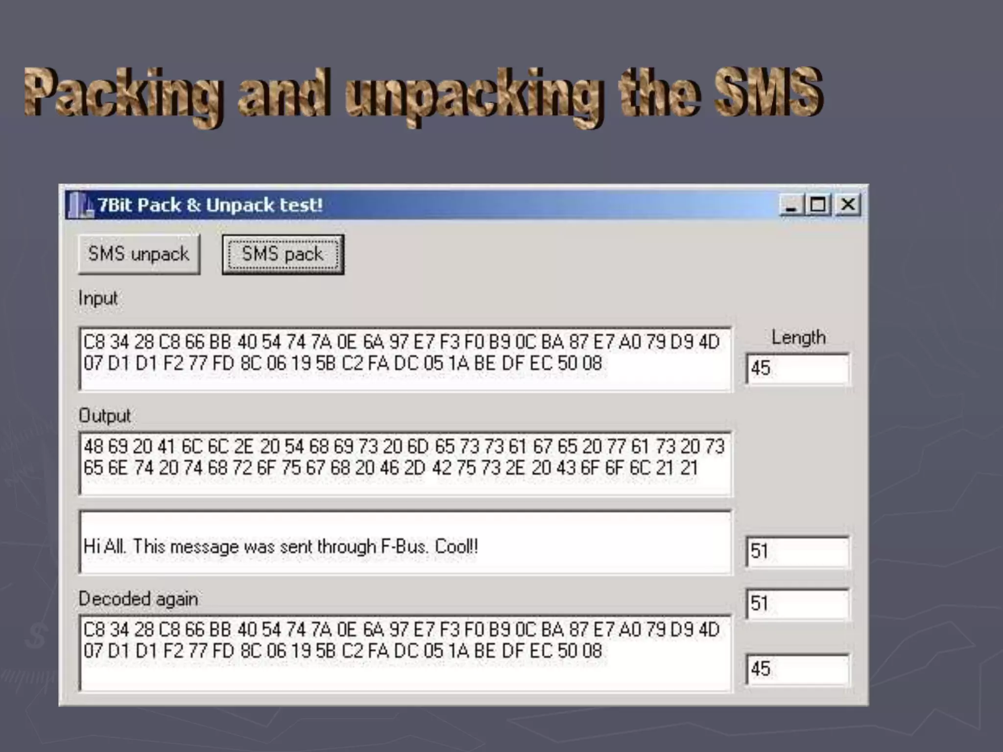
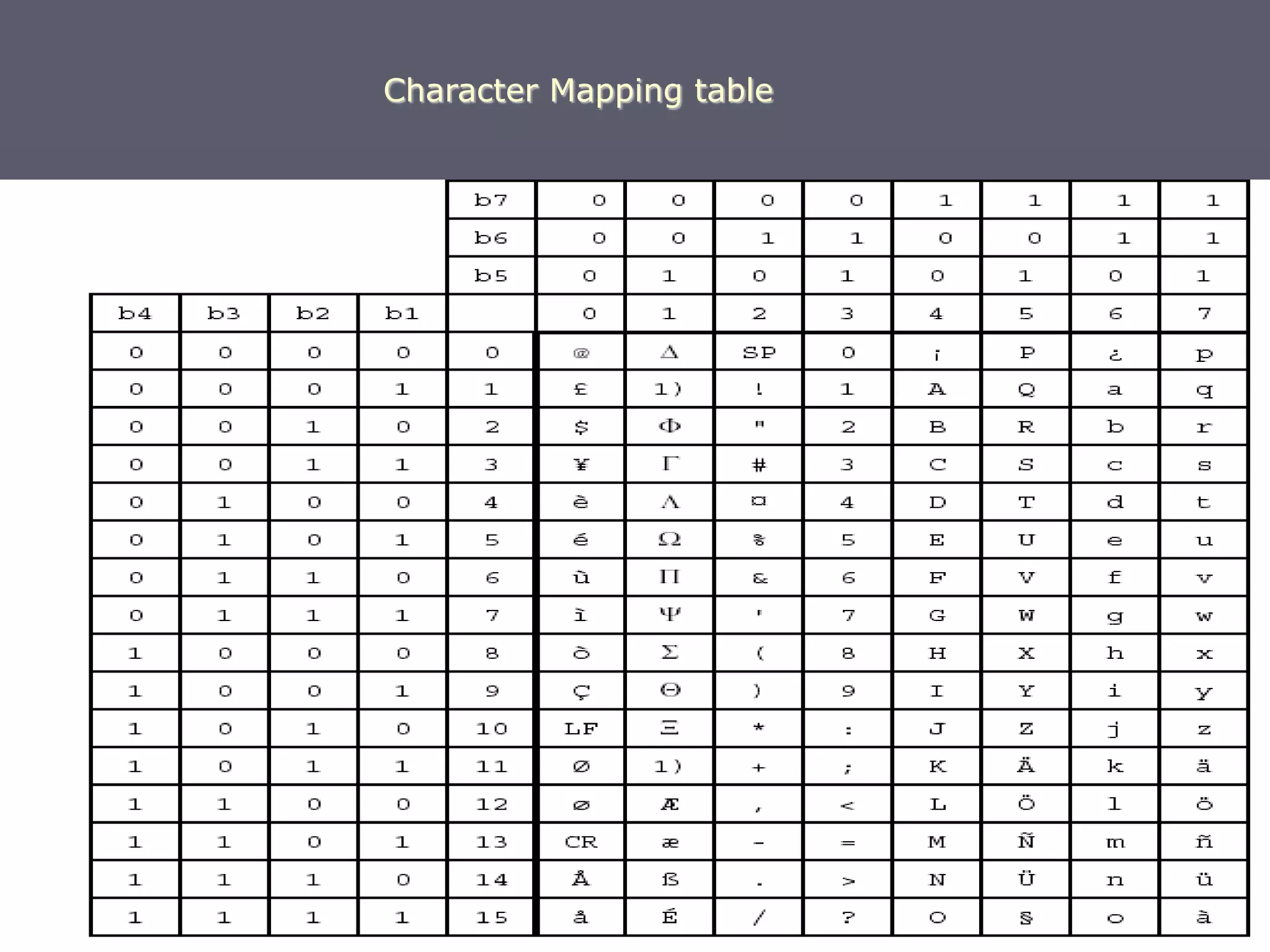
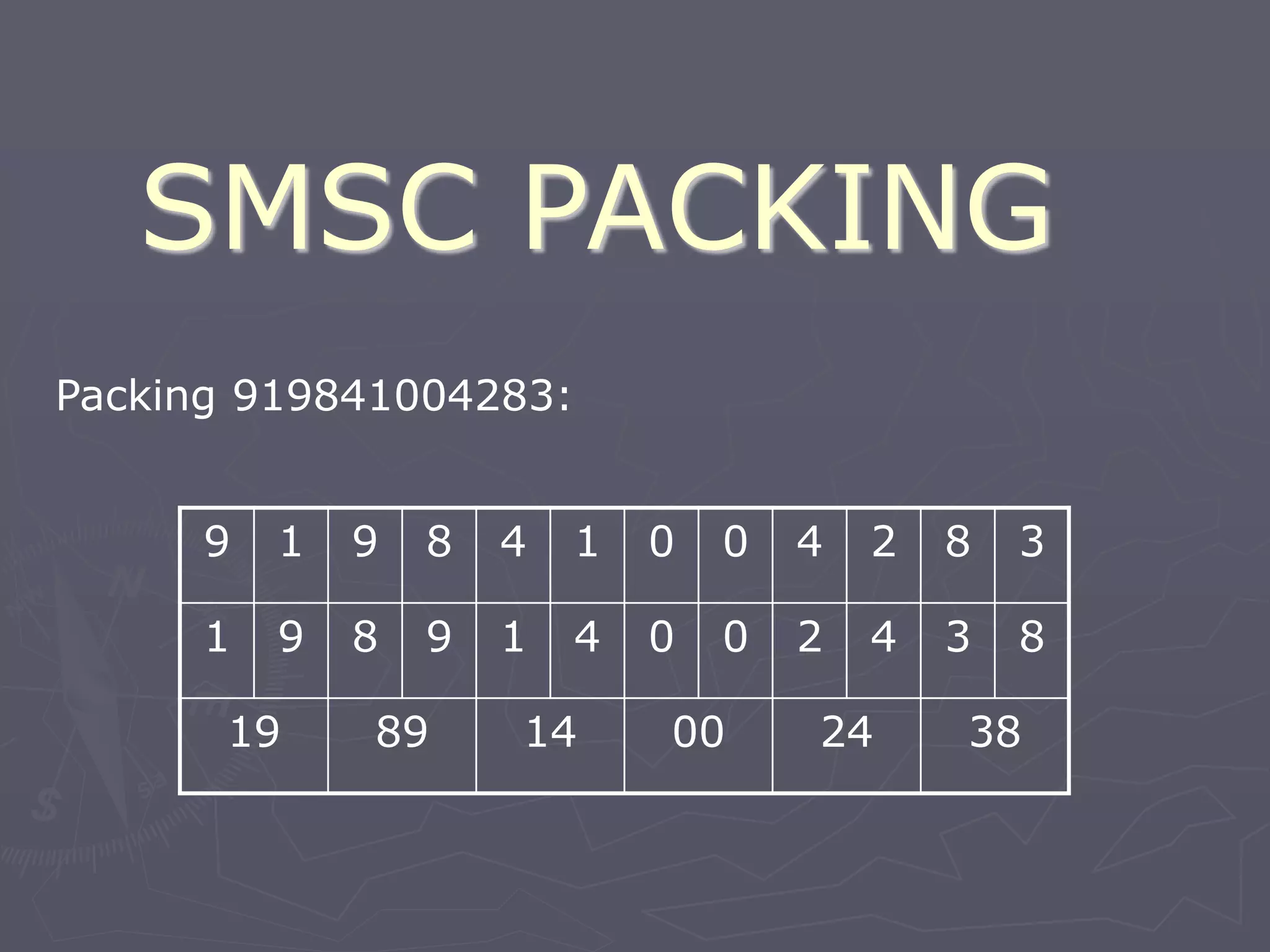
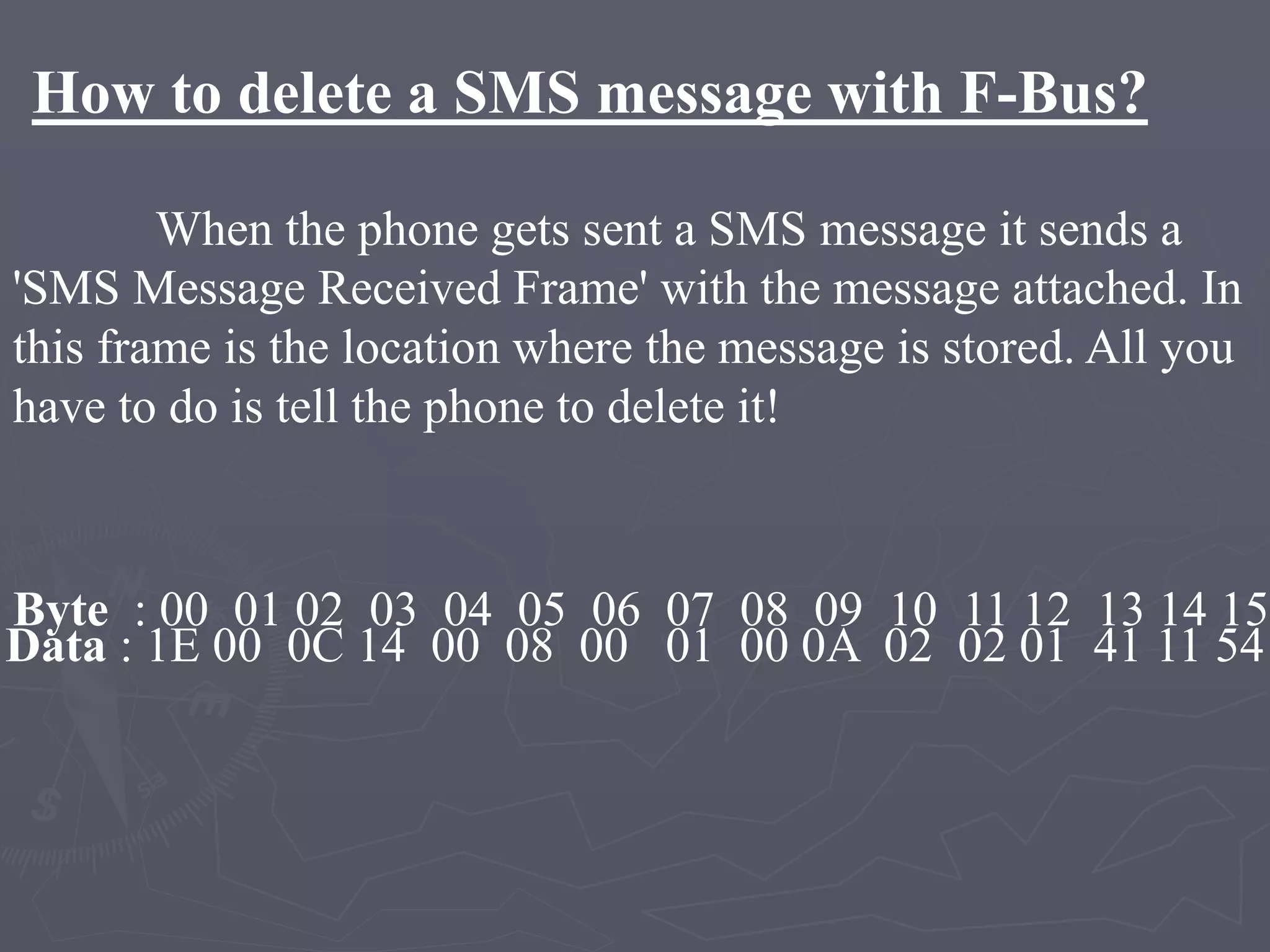
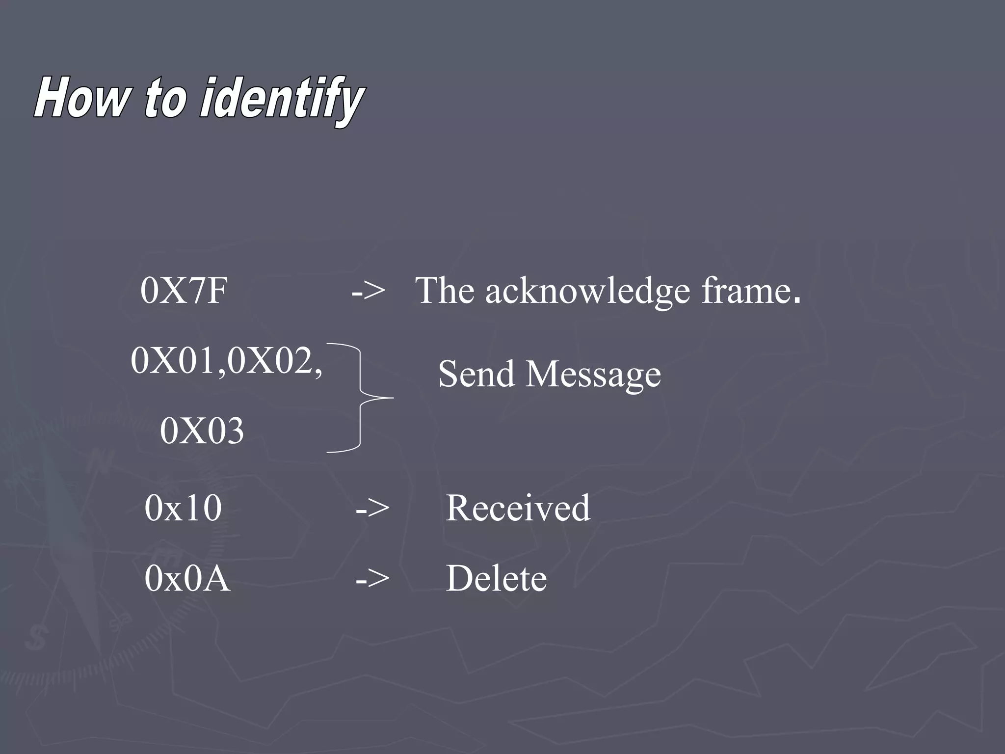
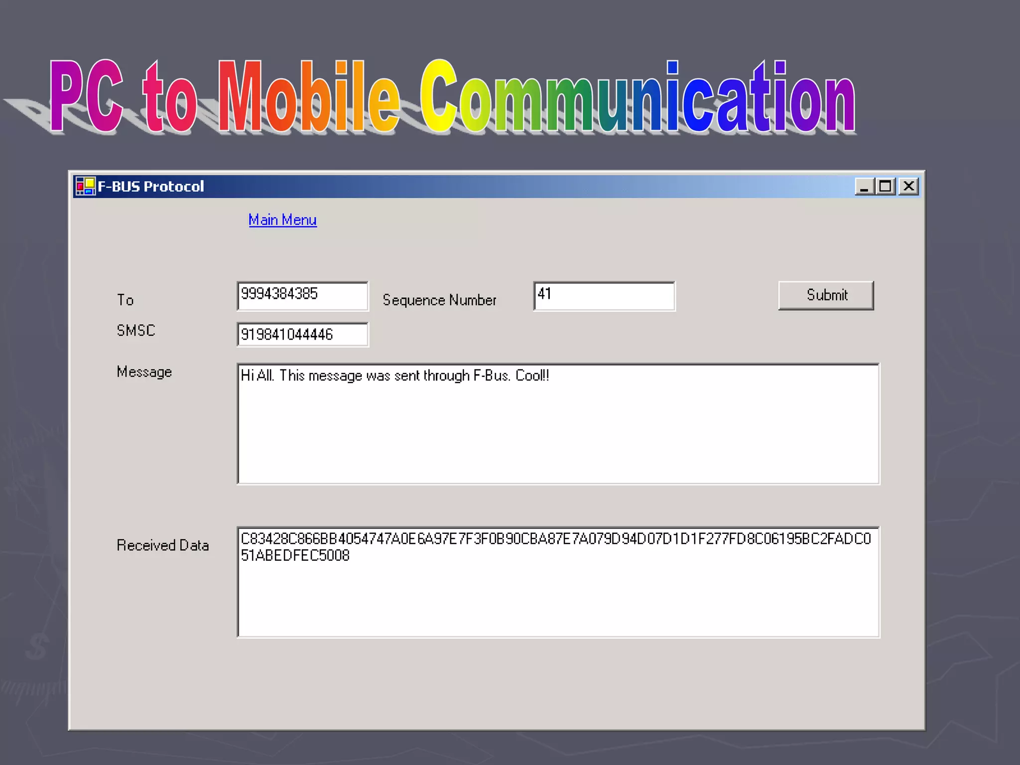
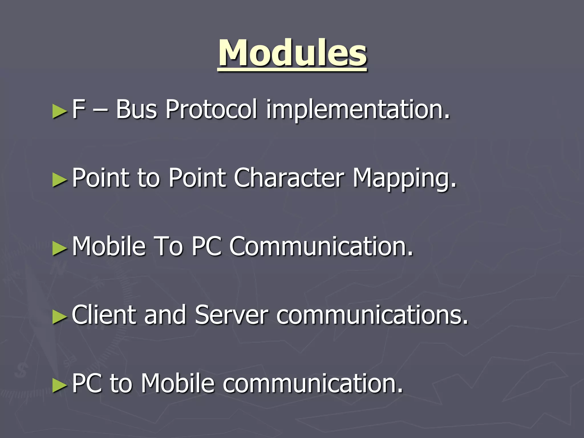
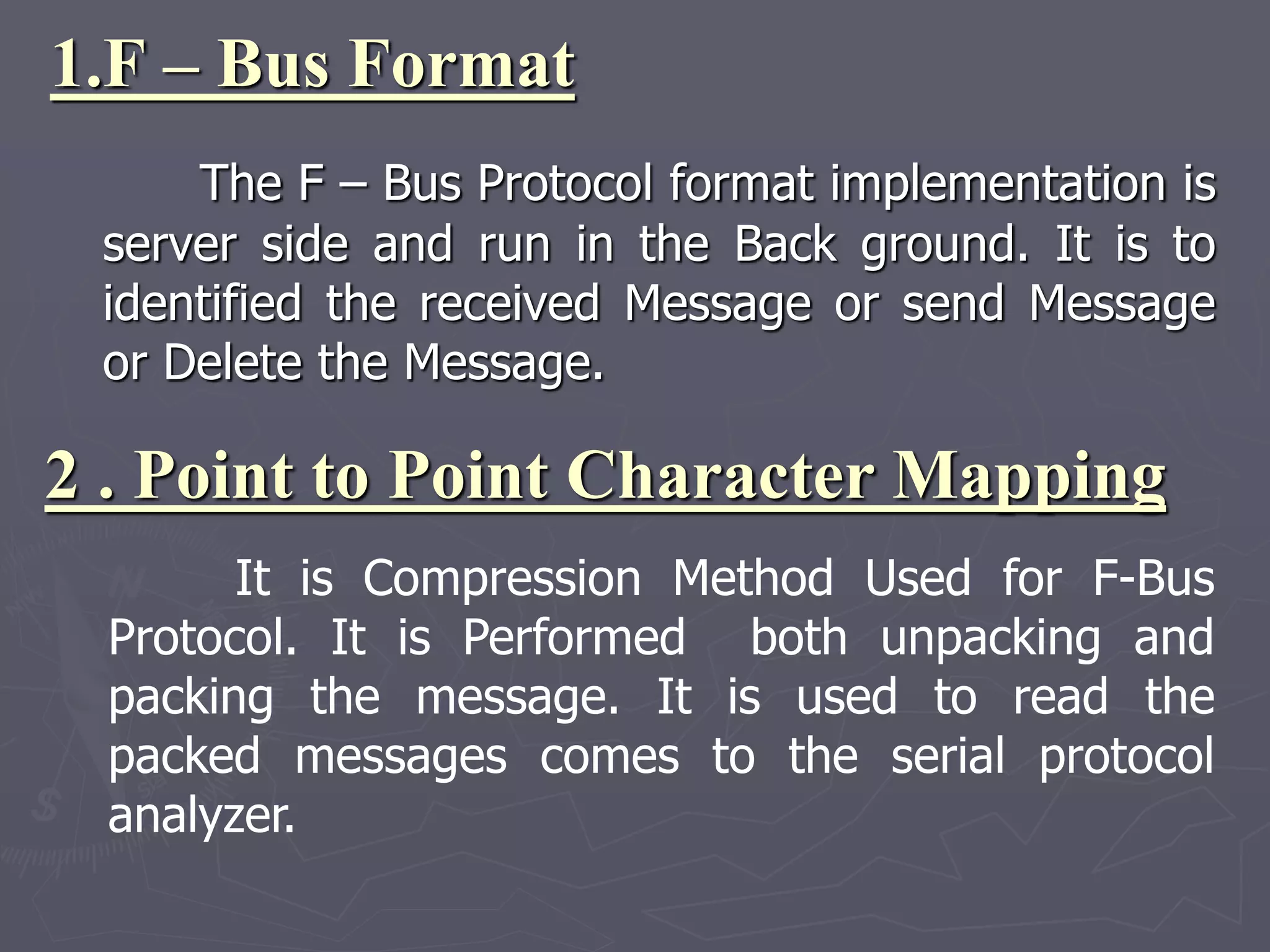
R.D.SIVAKUMAR,M.Sc.,M.Phil.,M.Tech.,
Assistant Professor of Computer Science &
Assistant Professor and Head, Department of M.Com.(CA),
Ayya Nadar Janaki Ammal College,
Sivakasi – 626 124.
Mobile: 099440-42243
e-mail : sivamsccsit@gmail.com
website: www.rdsivakumar.blogspot.in
F – BUS PROTOCOL
F – Bus Protocol
It is controlled mobile to any Embedded
systems
Most Nokia phones have F – Bus and M-Bus
connections that can be used to connect a phone to
a PC or a Micro controller.
ETSI -> European Telecommunications
Standard Institute
GSM Standard for F-Bus
Functions of F-Bus Protocol
High Speed of full duplex communications
Speed -> 1,15,200 Bps
8 bit data bus
No Parity bit, 1 stop bit,
Why we go to F-Bus Protocol?
 In M- Bus Protocol has Half – duplex
communications
M-Bus is slow speed compare F-Bus
Protocol. M-Bus Speed is 9600 Bps.
M- Bus is used for 1 stop bit and 1 parity
bit
Objective
F – Bus Protocol implemented in server side. The SMS to the
mobile will get into the server via the data cable connected. Then
corresponding actives performed with respect to the
commands/requests in the SMS received.
The server will respond to the mobile using the mobile
connected to the server. The server will transfer the
command/request to the corresponding PC. Every communication
among the server and the mobile will be done using F – Bus
Protocol.
How to connect the Mobile To PC
Data Cable -> RS232
How to connect Mobile To PC
NOKIA models
(supporting PC Connection)
 Nokia 3310
 Nokia 3315
 Nokia 6110
F- Bus Protocol Format
• Byte : 00 01 02 03 04 05 06 07 08 09 10 11 12 13 14 15
• Data : 1E 00 0C 02 00 59 00 01 00 01 02 00 07 91 16 14
SMS msg centre
• Byte : 16 17 18 19 20 21 22 23 24 25 26 27 28 29 30
• Data: 91 09 10 F0 00 00 00 00 15 00 00 00 33 0A81
• Byte : 31 32 33 34 35 36 37 38 39 40 41 42 43
Data : 40 30 87 00 47 00 00 00 00 00 A7 00 00
Phone number
• Byte : 44 45 46 47
• Data : 00 00 00 00
• Byte : 48 49 50 51 52 53 54 55 56 57
• Data : E8 32 9B FD 06 00 seq pad oddoreven
Start the Message : Hello
F – Bus Frame Header Format
• Byte 0 : F-Bus Frame ID. (0x1E - > cable)
(0X1C -> Infrared)
• Byte 1 : Destination address.
• Byte 2 : Source address.
• Byte 3 : Message Type or 'command'. 0x02
• Byte 4 & 5 : Message length. In our case it is
0x0059 bytes long .
SMS Frame Header
Byte 6 to 8 : Start of the SMS Frame Header.
0x00, 0x01, 0x00
Byte 9 to 11 : 0x01, 0x02, 0x00 Send SMS Message
SMSC (12 Bytes)
Byte 12 : SMS Centre number length. 7 bytes0x07.
Byte 13 : SMSC number type (e.g. 0x81-unknown
0x91-international 0xa1-national )
• Byte 14 to 23 : (Octet format) SMSC Phone.no
(TPDU) Transfer Protocol Data Unit
Byte 24 : Message Type
XXXX XXX1 = SMS Submit from the MS to the SC.
XXXX XXX0 = SMS Deliver from the SC to the MS.
Byte 25 : Message Reference if SMS Deliver &
Validity Indicator used (Not use)
Byte 26 : Protocol ID.
• Byte 27 : Data Coding Scheme.
• Byte 28 : Message Size is 0x33 in hex unpacked
Destination's Phone Number (12 Bytes)
Byte 29 : Destination's number length.
Byte 30 : Number type
Byte 31 to 40: (Octet format) Destination's Phone Number
Validity Period (VP)
Byte 41 : Validity-Period Code.
Byte 42 to 47: Service Centre Time Stamp
• The SMS Message (SMS-SUBMIT)
• Byte 48 to 92 : SMS message packed into 7
bit characters.
• Byte 93 : Always 0x00
• The F-Bus usual ending
• Byte 94 : Packet Sequence Number
• Byte 95 : Padding Byte
• Byte 96 & 97 : Odd & even checksum bytes.
0X7F -> The acknowledge frame.
0X01,0X02,
0X03
Send Message
0x10 -> Received
0x0A -> Delete
SMS – Point to Point Character Mapping
This is the Technical Specification that
describes the Packing of 7 – bit characters and
shows the standard character map. Packing ASCII
into 7 – bit characters is a pain, but is quite easy to
do.
h e l l o (ASCII characters)
68 65 6C 6C 6F (In hexadecimal)
1101000 1100101 1101100 1101100 1101111 (In Binary)
Reverse it
6F 6C 6C 65 68
1101111 1101100 1101100 1100101 1101000
Convert into the Hexa Decimal and the right shift
After Packing
110 11111101 10011011 00110010 11101000
06 FD 9B 32 E8
Again Reverse it
The message hello is therefore E8 32 9B FD 06 when
packed.
F – Bus Protocol Layers
SM _ AL
SM _ AL
SM _ TL SM _ TL
SM _ RL SM _ RL
SM _ LL SM _ LL
F – Bus Protocol Layers
►SM_LL ->Short Message Lower Layer
►SM_TL ->Short Message Transport Layer
►SM_RL -> Short Message Relay Layers
►SM_AL ->Short Message Application Layer
SM _ LL
►SM_LL is Short Message Lower Layer
►It is Provide the give to the service to the
Upper Layer for SM_RL.
SM _ RL
SM – RL is Short Message Relay Layer
It is Performing the acknowledegment , store and
retrive the data
SM-TL Layers
►Consist of Three Fields
 Address Length Fields
 Type of Address Fields
 Address Value Field of Variable Length Fields
Address Length Fields
►It is stored the address length type of
address and address value to be stored.
►It is integer represent numbers
►It is One Octet
Type of Address Fields
6 5 4 Explain
0 0 0 unknown
0 0 1 International Number
0 1 0 National Number
0 1 1 Network Specific Number
1 0 0 Subscriber Number
1 0 1 Alpha numeric
1 1 0 Abbreviated Number
1 1 1 Reserved Extension
►SM-AL is short Message Application Layer
►It is Performed the Message Passing
►It is containing Maximum Range is 4096
Bytes
SM - AL
Point to Point Character table
 It is Compression Method Used for F-Bus Protocol.
 It is Performed both unpacking and packing the
message.
 This is the Technical Specification that describes
the Packing of 7–bit characters and shows the standard
character map.
Sending SMS
h e l l o Message
68 65 6C 6C 6F ASCII
1101000 1100101 1101100 1101100 1101111 Binary
o
6F
1101111
l
6C
1101100
l
6C
1101100
e
65
1100101
h
68
1101000
Swap
110
06
11111101
FD
10011101
9B
00110010
32
11101000
E8
Pack
MESSAGE PACKING
Character Mapping table
Packing 919841004283:
9 1 9 8 4 1 0 0 4 2 8 3
3 8 2 4 0 0 1 4 8 9 1 9
38 24 00 14 89 19
NUMBER PACKING
SMSC PACKING
Packing 919841004283:
9 1 9 8 4 1 0 0 4 2 8 3
1 9 8 9 1 4 0 0 2 4 3 8
19 89 14 00 24 38
How to delete a SMS message with F-Bus?
When the phone gets sent a SMS message it sends a
'SMS Message Received Frame' with the message attached. In
this frame is the location where the message is stored. All you
have to do is tell the phone to delete it!
Byte : 00 01 02 03 04 05 06 07 08 09 10 11 12 13 14 15
Data : 1E 00 0C 14 00 08 00 01 00 0A 02 02 01 41 11 54
 41 to 47 ->In this Seven Byte to be generated
the sequence Number.
 Each and Every message Calculated the Separate
sequence Number Generated , until 47 byte.
 Suppose Another 8 ’th SMS receive Means Once
again Sequence Number Start the 41 Byte and go to 47
Byte.
Byte 03: Message Type = 0x14 - SMS Functions
Byte 04 & 05: Message Length = 0x0008 - 08 Bytes long
Byte 6 to 8: Start of the SMS Frame Header. 0x00, 0x01, 0x00
Byte 9: 0x0A Delete SMS Message
Byte 10: 0x02 = Memory Type - (0x03 = phone)
Byte 11: 0x02 = Location where SMS message stored.
Byte 12: 0x01
Byte 13: Packet Sequence Number
Byte 14 & 15: Odd & even checksum bytes
How to receive a SMS message with F-Bus?
When the phone gets sent a SMS message it sends a 'SMS
Message Received Frame' with the message attached. The
SMS send example above sends a SMS message back to my
phone (The same phone sending the message). Therefore
below is the SMS message that was sent above, but now
getting received by the phone.
1E 0C 00 7F 00 02 D1 00 CF 71
1E 0C 00 D2 00 26 01 00 00 03 56 20 30 34 2E 34 35 0A 32 31 2D 30 36 2D 30
31 0A 4E 48 4D 2D 35 0A 28 63 29 20 4E 4D
50 2E 00 01 41 3F A4
The first line is an Acknowledge command frame.
Notice how the destination and source addresses are now
swapped.
 This message is two bytes long with the two bytes
representing the message type received (0xD1) and the
sequence number (0x00).
0X7F -> The acknowledge frame.
0X01,0X02,
0X03
Send Message
0x10 -> Received
0x0A -> Delete
Modules
►F – Bus Protocol implementation.
►Point to Point Character Mapping.
►Mobile To PC Communication.
►Client and Server communications.
►PC to Mobile communication.
1.F – Bus Format
The F – Bus Protocol format implementation is
server side and run in the Back ground. It is to
identified the received Message or send Message
or Delete the Message.
2 . Point to Point Character Mapping
It is Compression Method Used for F-Bus
Protocol. It is Performed both unpacking and
packing the message. It is used to read the
packed messages comes to the serial protocol
analyzer.
3. Mobile to PC Communication
Mobile to PC Communication is held using
Data Cable (RS 232). Data Cable is connected
from Mobile to PC COM Port. That connection is
made to extract the information from Mobile to PC.
The COM Port will wait for incoming Messages.
4 . Client and Server Communications
After Extracting the information from the
Mobile, the server communications with the
corresponding Clients. The Server controls the
client through TCP/IP.
5 . PC to Mobile Communications
After the Client passed information to
server threw TCP/IP, the Server will give the
responses receives to the sender Mobile
Automatically.
F-Bus Protocol - R.D.Sivakumar

F-Bus Protocol - R.D.Sivakumar

  • 1.
    R.D.SIVAKUMAR,M.Sc.,M.Phil.,M.Tech., Assistant Professor ofComputer Science & Assistant Professor and Head, Department of M.Com.(CA), Ayya Nadar Janaki Ammal College, Sivakasi – 626 124. Mobile: 099440-42243 e-mail : sivamsccsit@gmail.com website: www.rdsivakumar.blogspot.in F – BUS PROTOCOL
  • 2.
    F – BusProtocol It is controlled mobile to any Embedded systems Most Nokia phones have F – Bus and M-Bus connections that can be used to connect a phone to a PC or a Micro controller.
  • 3.
    ETSI -> EuropeanTelecommunications Standard Institute
  • 4.
  • 5.
    Functions of F-BusProtocol High Speed of full duplex communications Speed -> 1,15,200 Bps 8 bit data bus No Parity bit, 1 stop bit,
  • 6.
    Why we goto F-Bus Protocol?  In M- Bus Protocol has Half – duplex communications M-Bus is slow speed compare F-Bus Protocol. M-Bus Speed is 9600 Bps. M- Bus is used for 1 stop bit and 1 parity bit
  • 7.
    Objective F – BusProtocol implemented in server side. The SMS to the mobile will get into the server via the data cable connected. Then corresponding actives performed with respect to the commands/requests in the SMS received. The server will respond to the mobile using the mobile connected to the server. The server will transfer the command/request to the corresponding PC. Every communication among the server and the mobile will be done using F – Bus Protocol.
  • 8.
    How to connectthe Mobile To PC
  • 9.
  • 10.
    How to connectMobile To PC
  • 11.
    NOKIA models (supporting PCConnection)  Nokia 3310  Nokia 3315  Nokia 6110
  • 12.
    F- Bus ProtocolFormat • Byte : 00 01 02 03 04 05 06 07 08 09 10 11 12 13 14 15 • Data : 1E 00 0C 02 00 59 00 01 00 01 02 00 07 91 16 14 SMS msg centre • Byte : 16 17 18 19 20 21 22 23 24 25 26 27 28 29 30 • Data: 91 09 10 F0 00 00 00 00 15 00 00 00 33 0A81 • Byte : 31 32 33 34 35 36 37 38 39 40 41 42 43 Data : 40 30 87 00 47 00 00 00 00 00 A7 00 00 Phone number
  • 13.
    • Byte :44 45 46 47 • Data : 00 00 00 00 • Byte : 48 49 50 51 52 53 54 55 56 57 • Data : E8 32 9B FD 06 00 seq pad oddoreven Start the Message : Hello
  • 14.
    F – BusFrame Header Format • Byte 0 : F-Bus Frame ID. (0x1E - > cable) (0X1C -> Infrared) • Byte 1 : Destination address. • Byte 2 : Source address. • Byte 3 : Message Type or 'command'. 0x02 • Byte 4 & 5 : Message length. In our case it is 0x0059 bytes long .
  • 15.
    SMS Frame Header Byte6 to 8 : Start of the SMS Frame Header. 0x00, 0x01, 0x00 Byte 9 to 11 : 0x01, 0x02, 0x00 Send SMS Message SMSC (12 Bytes) Byte 12 : SMS Centre number length. 7 bytes0x07. Byte 13 : SMSC number type (e.g. 0x81-unknown 0x91-international 0xa1-national )
  • 16.
    • Byte 14to 23 : (Octet format) SMSC Phone.no (TPDU) Transfer Protocol Data Unit Byte 24 : Message Type XXXX XXX1 = SMS Submit from the MS to the SC. XXXX XXX0 = SMS Deliver from the SC to the MS. Byte 25 : Message Reference if SMS Deliver & Validity Indicator used (Not use) Byte 26 : Protocol ID.
  • 17.
    • Byte 27: Data Coding Scheme. • Byte 28 : Message Size is 0x33 in hex unpacked Destination's Phone Number (12 Bytes) Byte 29 : Destination's number length. Byte 30 : Number type Byte 31 to 40: (Octet format) Destination's Phone Number Validity Period (VP) Byte 41 : Validity-Period Code. Byte 42 to 47: Service Centre Time Stamp
  • 18.
    • The SMSMessage (SMS-SUBMIT) • Byte 48 to 92 : SMS message packed into 7 bit characters. • Byte 93 : Always 0x00 • The F-Bus usual ending • Byte 94 : Packet Sequence Number • Byte 95 : Padding Byte • Byte 96 & 97 : Odd & even checksum bytes.
  • 19.
    0X7F -> Theacknowledge frame. 0X01,0X02, 0X03 Send Message 0x10 -> Received 0x0A -> Delete
  • 20.
    SMS – Pointto Point Character Mapping This is the Technical Specification that describes the Packing of 7 – bit characters and shows the standard character map. Packing ASCII into 7 – bit characters is a pain, but is quite easy to do. h e l l o (ASCII characters) 68 65 6C 6C 6F (In hexadecimal) 1101000 1100101 1101100 1101100 1101111 (In Binary) Reverse it
  • 21.
    6F 6C 6C65 68 1101111 1101100 1101100 1100101 1101000 Convert into the Hexa Decimal and the right shift After Packing 110 11111101 10011011 00110010 11101000 06 FD 9B 32 E8 Again Reverse it The message hello is therefore E8 32 9B FD 06 when packed.
  • 22.
    F – BusProtocol Layers SM _ AL SM _ AL SM _ TL SM _ TL SM _ RL SM _ RL SM _ LL SM _ LL
  • 23.
    F – BusProtocol Layers ►SM_LL ->Short Message Lower Layer ►SM_TL ->Short Message Transport Layer ►SM_RL -> Short Message Relay Layers ►SM_AL ->Short Message Application Layer
  • 24.
    SM _ LL ►SM_LLis Short Message Lower Layer ►It is Provide the give to the service to the Upper Layer for SM_RL. SM _ RL SM – RL is Short Message Relay Layer It is Performing the acknowledegment , store and retrive the data
  • 25.
    SM-TL Layers ►Consist ofThree Fields  Address Length Fields  Type of Address Fields  Address Value Field of Variable Length Fields
  • 26.
    Address Length Fields ►Itis stored the address length type of address and address value to be stored. ►It is integer represent numbers ►It is One Octet
  • 27.
  • 28.
    6 5 4Explain 0 0 0 unknown 0 0 1 International Number 0 1 0 National Number 0 1 1 Network Specific Number 1 0 0 Subscriber Number 1 0 1 Alpha numeric 1 1 0 Abbreviated Number 1 1 1 Reserved Extension
  • 29.
    ►SM-AL is shortMessage Application Layer ►It is Performed the Message Passing ►It is containing Maximum Range is 4096 Bytes SM - AL
  • 30.
    Point to PointCharacter table  It is Compression Method Used for F-Bus Protocol.  It is Performed both unpacking and packing the message.  This is the Technical Specification that describes the Packing of 7–bit characters and shows the standard character map. Sending SMS
  • 31.
    h e ll o Message 68 65 6C 6C 6F ASCII 1101000 1100101 1101100 1101100 1101111 Binary o 6F 1101111 l 6C 1101100 l 6C 1101100 e 65 1100101 h 68 1101000 Swap 110 06 11111101 FD 10011101 9B 00110010 32 11101000 E8 Pack MESSAGE PACKING
  • 33.
  • 34.
    Packing 919841004283: 9 19 8 4 1 0 0 4 2 8 3 3 8 2 4 0 0 1 4 8 9 1 9 38 24 00 14 89 19 NUMBER PACKING
  • 35.
    SMSC PACKING Packing 919841004283: 91 9 8 4 1 0 0 4 2 8 3 1 9 8 9 1 4 0 0 2 4 3 8 19 89 14 00 24 38
  • 36.
    How to deletea SMS message with F-Bus? When the phone gets sent a SMS message it sends a 'SMS Message Received Frame' with the message attached. In this frame is the location where the message is stored. All you have to do is tell the phone to delete it! Byte : 00 01 02 03 04 05 06 07 08 09 10 11 12 13 14 15 Data : 1E 00 0C 14 00 08 00 01 00 0A 02 02 01 41 11 54
  • 37.
     41 to47 ->In this Seven Byte to be generated the sequence Number.  Each and Every message Calculated the Separate sequence Number Generated , until 47 byte.  Suppose Another 8 ’th SMS receive Means Once again Sequence Number Start the 41 Byte and go to 47 Byte.
  • 38.
    Byte 03: MessageType = 0x14 - SMS Functions Byte 04 & 05: Message Length = 0x0008 - 08 Bytes long Byte 6 to 8: Start of the SMS Frame Header. 0x00, 0x01, 0x00 Byte 9: 0x0A Delete SMS Message Byte 10: 0x02 = Memory Type - (0x03 = phone) Byte 11: 0x02 = Location where SMS message stored. Byte 12: 0x01
  • 39.
    Byte 13: PacketSequence Number Byte 14 & 15: Odd & even checksum bytes How to receive a SMS message with F-Bus? When the phone gets sent a SMS message it sends a 'SMS Message Received Frame' with the message attached. The SMS send example above sends a SMS message back to my phone (The same phone sending the message). Therefore below is the SMS message that was sent above, but now getting received by the phone.
  • 40.
    1E 0C 007F 00 02 D1 00 CF 71 1E 0C 00 D2 00 26 01 00 00 03 56 20 30 34 2E 34 35 0A 32 31 2D 30 36 2D 30 31 0A 4E 48 4D 2D 35 0A 28 63 29 20 4E 4D 50 2E 00 01 41 3F A4 The first line is an Acknowledge command frame. Notice how the destination and source addresses are now swapped.  This message is two bytes long with the two bytes representing the message type received (0xD1) and the sequence number (0x00).
  • 41.
    0X7F -> Theacknowledge frame. 0X01,0X02, 0X03 Send Message 0x10 -> Received 0x0A -> Delete
  • 43.
    Modules ►F – BusProtocol implementation. ►Point to Point Character Mapping. ►Mobile To PC Communication. ►Client and Server communications. ►PC to Mobile communication.
  • 44.
    1.F – BusFormat The F – Bus Protocol format implementation is server side and run in the Back ground. It is to identified the received Message or send Message or Delete the Message. 2 . Point to Point Character Mapping It is Compression Method Used for F-Bus Protocol. It is Performed both unpacking and packing the message. It is used to read the packed messages comes to the serial protocol analyzer.
  • 45.
    3. Mobile toPC Communication Mobile to PC Communication is held using Data Cable (RS 232). Data Cable is connected from Mobile to PC COM Port. That connection is made to extract the information from Mobile to PC. The COM Port will wait for incoming Messages. 4 . Client and Server Communications After Extracting the information from the Mobile, the server communications with the corresponding Clients. The Server controls the client through TCP/IP.
  • 46.
    5 . PCto Mobile Communications After the Client passed information to server threw TCP/IP, the Server will give the responses receives to the sender Mobile Automatically.