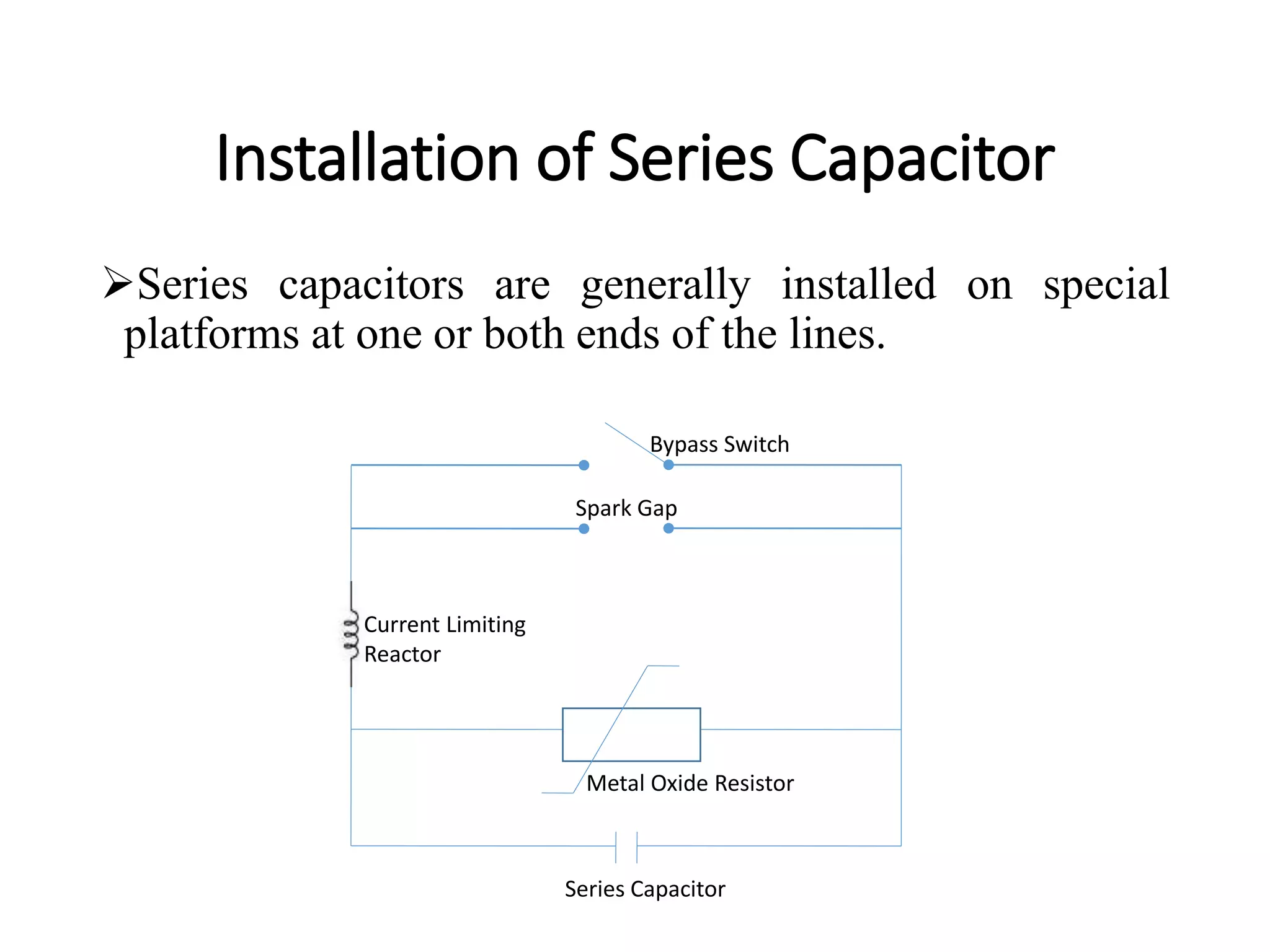
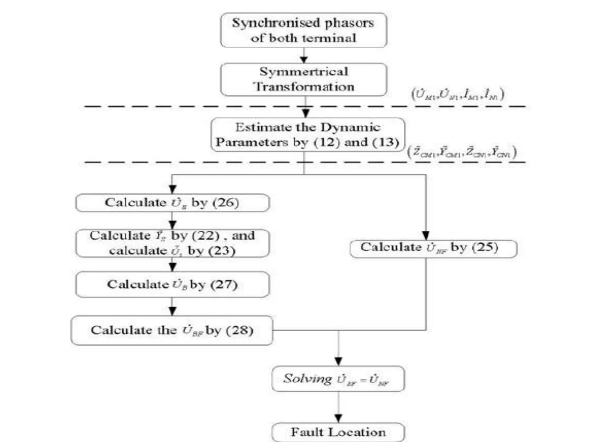
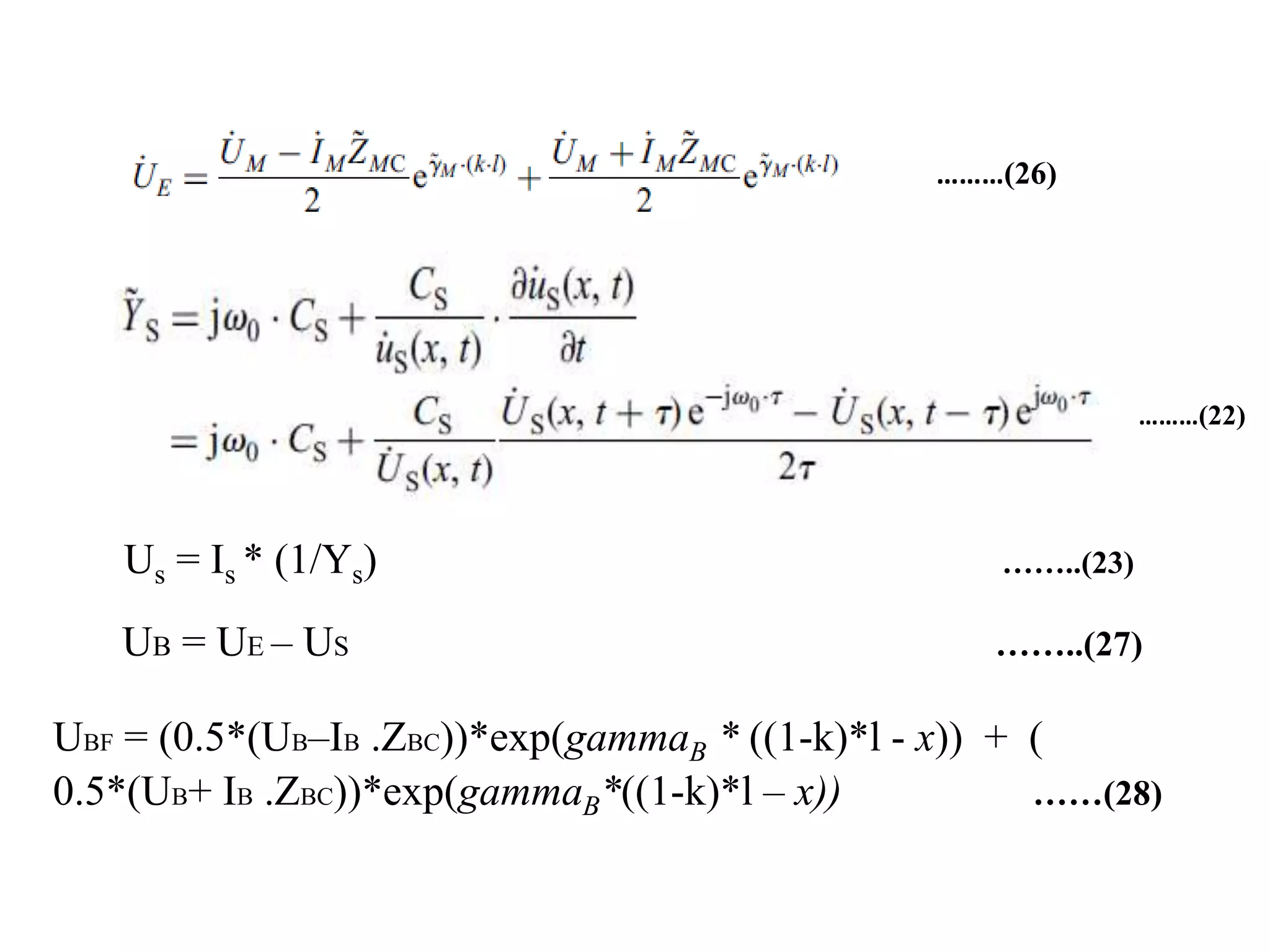
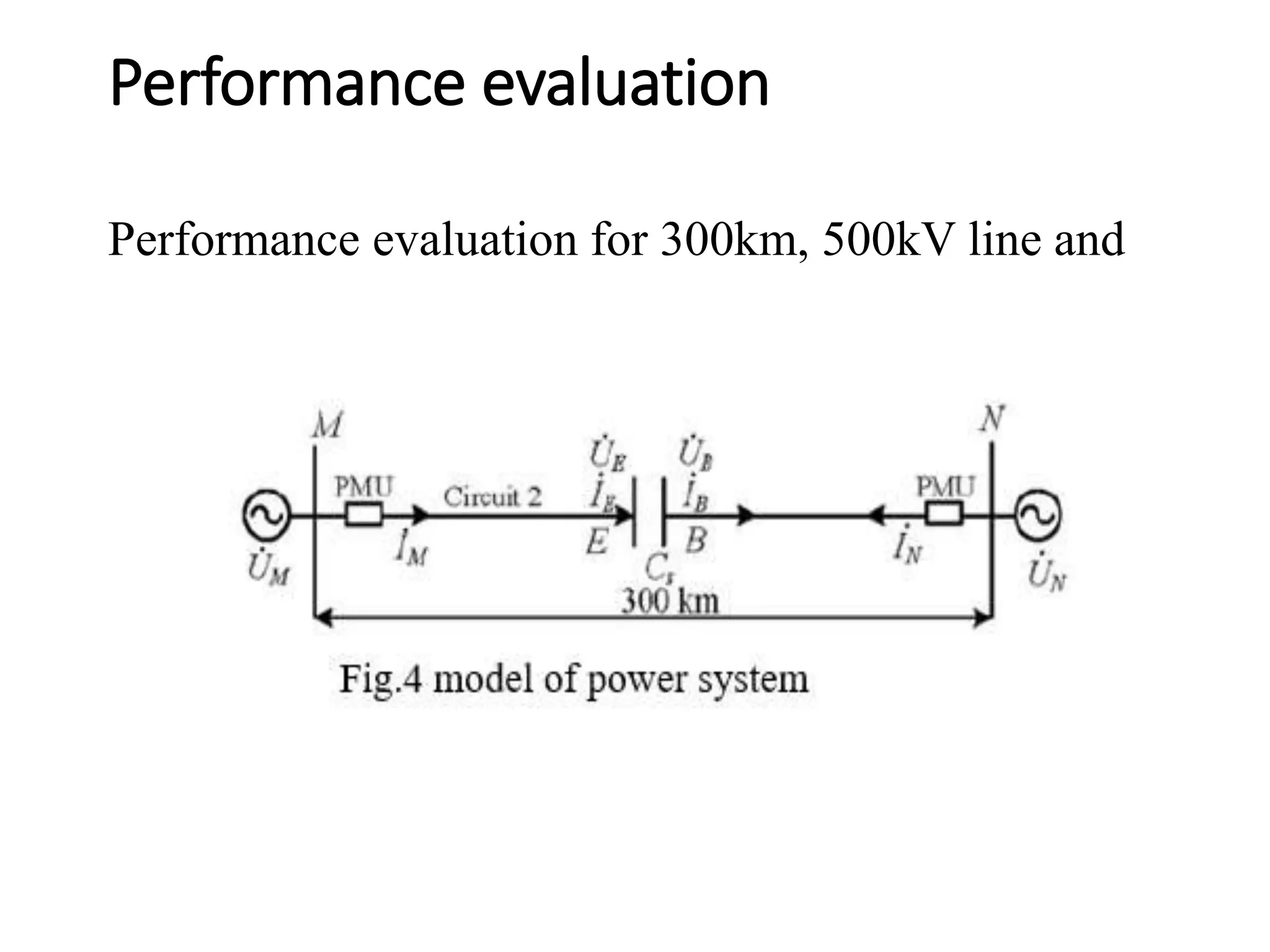
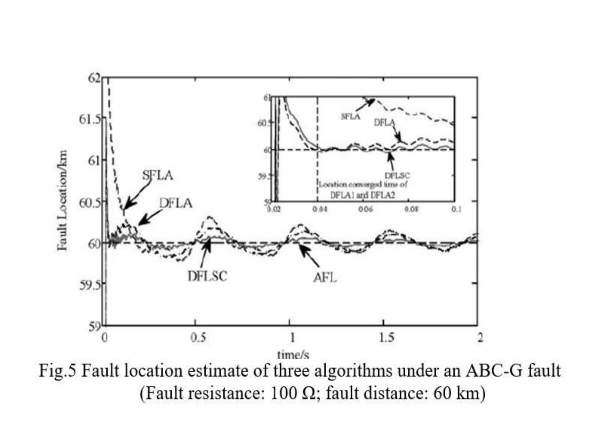
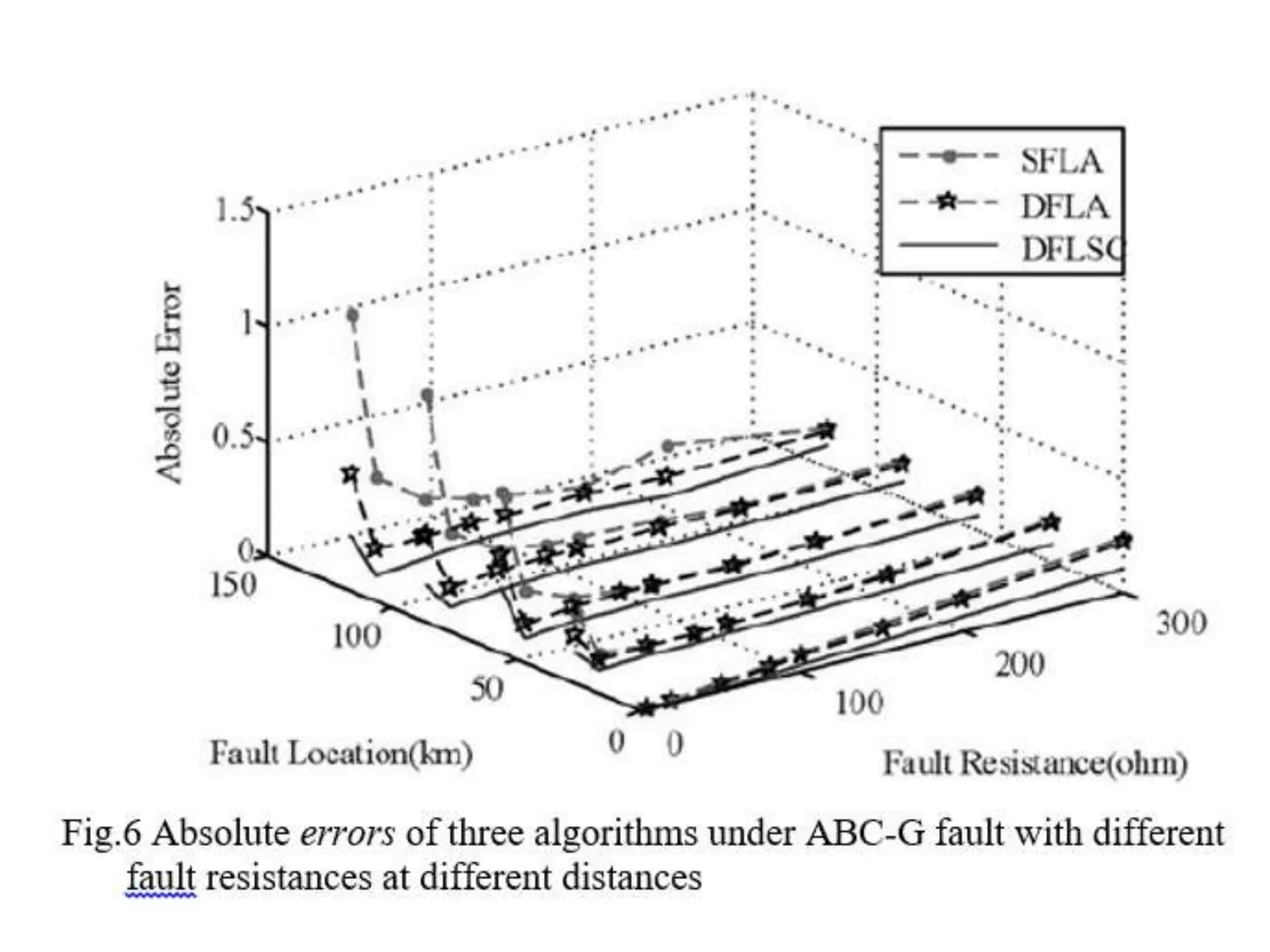
Fault location estimator for
series compensated
transmission line under
power oscillation conditions
Contents
• Introduction
• Need of compensation
• Types of compensation
• Objectives
• Advantages/ Problems
• Principle of the new fault location algorithm
• conclusion
Introduction to Compensation
Compensation of transmission lines is meant the use of
electrical circuits to modify the electrical characteristics
of the lines within the prescribed limit.
Need of Compensation
The line requires the compensation of transmission lines
due to:
Reduction of power transfer capability of lines which
reduces the margin between the stable and unstable
operation of system.
Ferranti effect.
Sub-synchronous resonance.
Various Types of Compensation
Various types of compensation techniques are used for
compensating the EHV lines:
Series compensation
Shunt compensation-SVS (Synchronous voltage
Source)
Synchronous condenser
Objectives of Series and Shunt
Compensation
Main objective of series and shunt compensation of
EHV lines for transmitting bulk power over the long
distance may be stated as:
To improve transfer capability along with increased
steady state and transient stability limits.
To obtain flat voltage profile as possible along the
length of the EHV line while maintaining the equal
sending end and receiving end voltage.
To avoid degree of compensation leading to sub-
synchronous resonance.
SERIES COMPENSATION
The series capacitor offers an effective and economic
means for improving stability limits of long distance
transmission by reducing the net reactance of
transmission line.
In the present case of 400kv and 600km transmission
system, the maximum value of receiving end power,
compensation efficiency, optimum value of series
capacitive reactance are obtained using computer
program.
Series compensation is used in long lines to increase
transmission capacity, improvement of system stability
and to obtain correct load division between parallel
circuits.
Series capacitors are connected in series with the line to
reduce the net impedance of the transmission line. This
reduced impedance causes the reduced voltage drop
across the line.
Series capacitors are generally installed on special
platforms at one or both ends of the lines.
Installation of Series Capacitor
Series capacitors are generally installed on special
platforms at one or both ends of the lines.
Series Capacitor
Current Limiting
Reactor
Spark Gap
Bypass Switch
Metal Oxide Resistor
Bypass switch
the bypass switch must be able to carry the rated current and
the rated short-circuit current in the closed position, as well as
withstand the overvoltages specified across the open gap and
phase-to-earth.
METAL OXYDE VARISTORS (MOVs)
Metal oxide varistors, which are connected in parallel
with the capacitors , provide overvoltage protection of the
capacitors during and after power system faults and thus
are conducting a large part of the fault current. MOVs are
then protected by the spark gap activation against
excessive energy absorption
SPARK GAP
• In case of operation of the MOV protection relay, the spark gap is
force-triggered by the protection and control system.
Advantage of Series Compensation
There are various advantage of series compensation:
Increase in power transfer capability
Improvement of system stability
Load division among parallel lines
Control of voltage
Location of Series Capacitor
Location along the line.
Location at one or both ends of line section on the line
sides in the switching stations.
Location between Bus Bars and switching station.
Problems Associated with Series
Compensation
Sub – Synchronous Resonance
Sustain oscillation
Unreliable protection of transmission lines
Application of Series Compensation
They have been primarily used to improve system stability
and to obtain the desired load division among parallel lines.
High compensation levels also increase the complexity of
protective relaying and the probability of sub-synchronous
resonance.
A practical upper limit to the degree of series compensation
is about 80%.
Following are some of the key considerations in the
application of series capacitor banks:
Voltage rise due to reactive current: Voltage rise of on one
side of the capacitor may be excessive when the line
reactive-current flow is high, as might occur during heavy
power transfers.
Bypassing and reinsertion: provision is made for
bypassing the capacitor during faults and reinsertion after
fault clearing. Speed of reinsertion may be an important
factor in maintaining transient stability.
Present trend is to use nonlinear resistors of zinc oxide
which have the advantage that reinsertion is essentially
instantaneous
SHUNT COMPENSATION- SVS
Shunt compensation may consist of static (using
capacitor and reactor) or synchronous compensation to
avoid voltage stability.
Shunt capacitors supply reactive power and boost local
voltages. They are used throughout the system and are
applied in a wide range of sizes.
The principal advantages of shunt capacitors are their
low cost and their flexibility of installation and
operation.
The principal disadvantage of shunt capacitors is that
their reactive power output is proportional to the square
of the voltage.
Application of shunt compensation
Shunt capacitors are used to compensate for the XI2
losses in transmission system and to ensure satisfactory
voltage levels during heavy loading conditions.
Switching of capacitor banks provides a convenient
means of controlling transmission system voltages.
Types of SVS
Self Saturated Reactor (SR)
Thyristor Controlled Reactor (TCR)
Thyristor Switched Capacitor (TSC)
 Fixed Capacitor (FC), Thyristor Controlled Reactor
(TCR) scheme
Thyristor Switched Capacitor (TSC), Thyristor
Controlled Reactor(TCR) scheme
Advantages of SVS
Increased power transfer capability
 Enhancement of transient stability
The dynamic response of SVS is very fast
Steady –State and temporary overvoltage can be
controlled
SYNCHRONOUS CONDENSER
 A synchronous condenser is a synchronous machine running
without a prime mover or a mechanical load. By controlling
the field excitation, it can be made to either generate or
absorb reactive power. With a voltage regulator, it can
automatically adjust the reactive power output to maintain
constant terminal voltage.
Synchronous compensators contribute to system short-circuit
capacity. Their reactive power production is not affected by
the system voltage.
UB = UE − US
US = IS*1/(jw0CS)
IB = IE
Principle of the new fault location algorithm
Terms can be calculated
(1) Static-fault locator algorithm for transmission line
Based on the distributed parameter model of transmission line, it is easy
to obtain the voltage and current at a distance x from the terminal N
Where UBF and UNF are the voltage estimates at point F, respectively.
Since the UBF is equal to UNF, the fault location can be expressed as
(2.1) Dynamic fault locator for two-terminal
transmission Lines
Dynamic parameters estimator
From here we can calculate characteristics impedance (Zc) and
propagation constant (gamma)
Zc = sqrt (Z/Y)
gamma = sqrt (Z.Y)
(2.2)Analysis of the compensation capacity’s
influence
…….(a)
here US(x, t) = us (x, t) * exp(jw0t)
……..(b)
This is Equivalent admittance
…….(c)
uS(x, t) = Us (x, t) * exp(-jw0t) ……..(d)
From equation (b), (c), and (d)
Hence, a corrected voltage drop across the SC can be
obtained
Us = Is * (1/Ys)
Ys
2.3 Dynamic fault locator algorithm:
The fault section needs to be identified since the fault could be
occurred randomly in any side of the SC. A method is employed
to identify the fault section. The criterion is expressed as follows
fault located at the left-hand side of SC
fault located at the right-hand side of SC
where 1/C is an indicator of the fault location relative to SC,
(1/C)set is the setting, it can be set by (1/C)set = 0.5 × (1/Cs).
Fig. flowchart of the iteration
uS(x, t) = Us (x, t) * exp(-jw0t) ………..(21)
Ys ……(22)
Us = Is * (1/Ys) ……..(23)
………(22)
………(26)
Us = Is * (1/Ys) ……..(23)
UB = UE – US ……..(27)
UBF = (0.5*(UB–IB .ZBC))*exp(gammaB * ((1-k)*l - x)) + (
0.5*(UB+ IB .ZBC))*exp(gammaB*((1-k)*l – x)) ……(28)
Performance evaluation
Performance evaluation for 300km, 500kV line and
Conclusion
This paper proposes a novel fault location algorithm for SC
compensated transmission line under dynamic conditions by
using synchronised phasor measurements obtained by PMUs.
The influence on the SC caused by power oscillation has been
fully considered by DFLSC. The algorithm gives better fault
localisation estimate under power oscillation condition with
comparison to the fault location algorithms which did not
consider the dynamic characteristics of line or the SC.
Thank you

fault location estimator in series compensator

  • 1.
    Fault location estimatorfor series compensated transmission line under power oscillation conditions
  • 2.
    Contents • Introduction • Needof compensation • Types of compensation • Objectives • Advantages/ Problems • Principle of the new fault location algorithm • conclusion
  • 3.
    Introduction to Compensation Compensationof transmission lines is meant the use of electrical circuits to modify the electrical characteristics of the lines within the prescribed limit.
  • 4.
    Need of Compensation Theline requires the compensation of transmission lines due to: Reduction of power transfer capability of lines which reduces the margin between the stable and unstable operation of system. Ferranti effect. Sub-synchronous resonance.
  • 5.
    Various Types ofCompensation Various types of compensation techniques are used for compensating the EHV lines: Series compensation Shunt compensation-SVS (Synchronous voltage Source) Synchronous condenser
  • 6.
    Objectives of Seriesand Shunt Compensation Main objective of series and shunt compensation of EHV lines for transmitting bulk power over the long distance may be stated as: To improve transfer capability along with increased steady state and transient stability limits. To obtain flat voltage profile as possible along the length of the EHV line while maintaining the equal sending end and receiving end voltage. To avoid degree of compensation leading to sub- synchronous resonance.
  • 7.
    SERIES COMPENSATION The seriescapacitor offers an effective and economic means for improving stability limits of long distance transmission by reducing the net reactance of transmission line. In the present case of 400kv and 600km transmission system, the maximum value of receiving end power, compensation efficiency, optimum value of series capacitive reactance are obtained using computer program.
  • 8.
    Series compensation isused in long lines to increase transmission capacity, improvement of system stability and to obtain correct load division between parallel circuits. Series capacitors are connected in series with the line to reduce the net impedance of the transmission line. This reduced impedance causes the reduced voltage drop across the line. Series capacitors are generally installed on special platforms at one or both ends of the lines.
  • 9.
    Installation of SeriesCapacitor Series capacitors are generally installed on special platforms at one or both ends of the lines. Series Capacitor Current Limiting Reactor Spark Gap Bypass Switch Metal Oxide Resistor
  • 10.
    Bypass switch the bypassswitch must be able to carry the rated current and the rated short-circuit current in the closed position, as well as withstand the overvoltages specified across the open gap and phase-to-earth. METAL OXYDE VARISTORS (MOVs) Metal oxide varistors, which are connected in parallel with the capacitors , provide overvoltage protection of the capacitors during and after power system faults and thus are conducting a large part of the fault current. MOVs are then protected by the spark gap activation against excessive energy absorption
  • 11.
    SPARK GAP • Incase of operation of the MOV protection relay, the spark gap is force-triggered by the protection and control system.
  • 12.
    Advantage of SeriesCompensation There are various advantage of series compensation: Increase in power transfer capability Improvement of system stability Load division among parallel lines Control of voltage
  • 13.
    Location of SeriesCapacitor Location along the line. Location at one or both ends of line section on the line sides in the switching stations. Location between Bus Bars and switching station.
  • 14.
    Problems Associated withSeries Compensation Sub – Synchronous Resonance Sustain oscillation Unreliable protection of transmission lines
  • 15.
    Application of SeriesCompensation They have been primarily used to improve system stability and to obtain the desired load division among parallel lines. High compensation levels also increase the complexity of protective relaying and the probability of sub-synchronous resonance. A practical upper limit to the degree of series compensation is about 80%.
  • 16.
    Following are someof the key considerations in the application of series capacitor banks: Voltage rise due to reactive current: Voltage rise of on one side of the capacitor may be excessive when the line reactive-current flow is high, as might occur during heavy power transfers. Bypassing and reinsertion: provision is made for bypassing the capacitor during faults and reinsertion after fault clearing. Speed of reinsertion may be an important factor in maintaining transient stability. Present trend is to use nonlinear resistors of zinc oxide which have the advantage that reinsertion is essentially instantaneous
  • 17.
    SHUNT COMPENSATION- SVS Shuntcompensation may consist of static (using capacitor and reactor) or synchronous compensation to avoid voltage stability. Shunt capacitors supply reactive power and boost local voltages. They are used throughout the system and are applied in a wide range of sizes. The principal advantages of shunt capacitors are their low cost and their flexibility of installation and operation. The principal disadvantage of shunt capacitors is that their reactive power output is proportional to the square of the voltage.
  • 18.
    Application of shuntcompensation Shunt capacitors are used to compensate for the XI2 losses in transmission system and to ensure satisfactory voltage levels during heavy loading conditions. Switching of capacitor banks provides a convenient means of controlling transmission system voltages.
  • 19.
    Types of SVS SelfSaturated Reactor (SR) Thyristor Controlled Reactor (TCR) Thyristor Switched Capacitor (TSC)  Fixed Capacitor (FC), Thyristor Controlled Reactor (TCR) scheme Thyristor Switched Capacitor (TSC), Thyristor Controlled Reactor(TCR) scheme
  • 20.
    Advantages of SVS Increasedpower transfer capability  Enhancement of transient stability The dynamic response of SVS is very fast Steady –State and temporary overvoltage can be controlled
  • 21.
    SYNCHRONOUS CONDENSER  Asynchronous condenser is a synchronous machine running without a prime mover or a mechanical load. By controlling the field excitation, it can be made to either generate or absorb reactive power. With a voltage regulator, it can automatically adjust the reactive power output to maintain constant terminal voltage. Synchronous compensators contribute to system short-circuit capacity. Their reactive power production is not affected by the system voltage.
  • 22.
    UB = UE− US US = IS*1/(jw0CS) IB = IE Principle of the new fault location algorithm Terms can be calculated
  • 23.
    (1) Static-fault locatoralgorithm for transmission line Based on the distributed parameter model of transmission line, it is easy to obtain the voltage and current at a distance x from the terminal N Where UBF and UNF are the voltage estimates at point F, respectively. Since the UBF is equal to UNF, the fault location can be expressed as
  • 24.
    (2.1) Dynamic faultlocator for two-terminal transmission Lines Dynamic parameters estimator From here we can calculate characteristics impedance (Zc) and propagation constant (gamma) Zc = sqrt (Z/Y) gamma = sqrt (Z.Y)
  • 25.
    (2.2)Analysis of thecompensation capacity’s influence …….(a) here US(x, t) = us (x, t) * exp(jw0t)
  • 26.
    ……..(b) This is Equivalentadmittance …….(c) uS(x, t) = Us (x, t) * exp(-jw0t) ……..(d) From equation (b), (c), and (d) Hence, a corrected voltage drop across the SC can be obtained Us = Is * (1/Ys) Ys
  • 27.
    2.3 Dynamic faultlocator algorithm: The fault section needs to be identified since the fault could be occurred randomly in any side of the SC. A method is employed to identify the fault section. The criterion is expressed as follows fault located at the left-hand side of SC fault located at the right-hand side of SC where 1/C is an indicator of the fault location relative to SC, (1/C)set is the setting, it can be set by (1/C)set = 0.5 × (1/Cs).
  • 28.
    Fig. flowchart ofthe iteration uS(x, t) = Us (x, t) * exp(-jw0t) ………..(21) Ys ……(22) Us = Is * (1/Ys) ……..(23)
  • 30.
    ………(22) ………(26) Us = Is* (1/Ys) ……..(23) UB = UE – US ……..(27) UBF = (0.5*(UB–IB .ZBC))*exp(gammaB * ((1-k)*l - x)) + ( 0.5*(UB+ IB .ZBC))*exp(gammaB*((1-k)*l – x)) ……(28)
  • 31.
  • 35.
    Conclusion This paper proposesa novel fault location algorithm for SC compensated transmission line under dynamic conditions by using synchronised phasor measurements obtained by PMUs. The influence on the SC caused by power oscillation has been fully considered by DFLSC. The algorithm gives better fault localisation estimate under power oscillation condition with comparison to the fault location algorithms which did not consider the dynamic characteristics of line or the SC.
  • 36.