Downloaded 250 times


![TABLE OF CONTENTS B-64305EN/03
c-4
5.2.7 Inputting CNC Parameters ...................................................................................187
5.2.8 Inputting Pitch Error Compensation Amount.......................................................188
5.2.9 Inputting Custom Macro Variable Values............................................................188
5.2.10 Inputting Tool Compensation Amount.................................................................188
5.2.11 Inputting Part Programs........................................................................................188
5.3 AUTOMATIC DATA BACKUP ...................................................................189
6 INTERFACE BETWEEN CNC AND PMC...........................................194
6.1 WHAT IS PMC?.........................................................................................195
6.1.1 Basic Configuration of PMC................................................................................195
6.1.2 I/O Signals of PMC..............................................................................................195
6.1.3 PMC Signal Addresses.........................................................................................196
6.1.4 System Relay Addresses (R9000) ........................................................................198
6.2 PMC SPECIFICATIONS............................................................................202
6.2.1 Basic Specifications .............................................................................................202
6.3 OPERATING THE PMC SCREEN.............................................................207
6.3.1 Transition of the PMC Screens.............................................................................209
6.4 PMC DIAGNOSIS AND MAINTENANCE SCREENS ([PMCMNT])...........210
6.4.1 Monitoring PMC Signal Status ([STATUS] Screen) ...........................................210
6.4.2 Checking PMC Alarms ([ALARM] Screen)........................................................212
6.4.3 Setting and Displaying Variable Timers ([TIMER] Screen)................................213
6.4.4 Setting and Displaying Counter Values ([COUNTR] Screen).............................215
6.4.5 Setting and Displaying Keep Relays ([KEEPRL] Screen)...................................217
6.4.6 Setting and Displaying Data Tables ([DATA] Screen)........................................218
6.4.7 Data Input/Output ([I/O] Screen) .........................................................................223
6.4.8 Displaying I/O Link Connection Status ([I/OLNK] Screen)................................225
6.4.9 Signal Trace Function ([TRACE] Screen) ...........................................................227
6.4.10 Setting of Trace Parameter ([TRCPRM] Screen).................................................228
6.4.11 Execution of Trace ...............................................................................................232
6.4.11.1 Operation after execution of trace ................................................................... 233
6.4.11.2 Automatic start of trace setting........................................................................ 235
6.4.12 MONITORING I/O DIAGNOSIS ([I/ODGN] SCREEN)...................................236
6.5 LADDER DIAGRAM MONITOR AND EDITOR SCREENS ([PMCLAD]) ...239
6.5.1 Displaying a Program List ([LIST] Screen) .........................................................240
6.5.2 Monitoring Ladder Diagrams ([LADDER] Screen).............................................242
6.5.3 Editing Ladder Programs......................................................................................245
6.5.3.1 NET EDITOR Screen...................................................................................... 247
6.5.4 PROGRAM LIST EDITOR Screen .....................................................................249
6.5.5 Collective Monitor Function ................................................................................250
6.5.5.1 COLLECTIVE MONITOR Screen ................................................................. 251
6.6 LIST OF ADDRESSES ..............................................................................254
7 EMBEDDED ETHERNET FUNCTION ................................................276
7.1 EMBEDDED ETHERNET PORT AND PCMCIA ETHERNET CARD.........276
7.2 SETTING UP THE EMBEDDED ETHERNET FUNCTION ........................277
7.2.1 Setting of the FOCAS2/Ethernet Function...........................................................277
7.2.1.1 Operation on the FOCAS2/Ethernet setting screen ......................................... 277
7.2.1.2 Example of setting the FOCAS2/Ethernet function......................................... 280
7.2.2 Setting of the FTP File Transfer Function............................................................280
7.2.2.1 Operation on the FTP file transfer setting screen ............................................ 281
7.2.2.2 Related NC parameters.................................................................................... 283
7.2.2.3 Example of setting the FTP file transfer function............................................ 284
7.2.3 Setting Up the DNS/DHCP Function...................................................................285
7.2.3.1 Setting up DNS................................................................................................ 285](https://image.slidesharecdn.com/fanuc0imaintenancemanual-140802043306-phpapp01/85/Fanuc-0i-maintenance-manual-CNC-milling-machine-14-320.jpg)
![B-64305EN/03 1.DISPLAY AND OPERATION
- 3 -
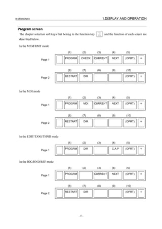
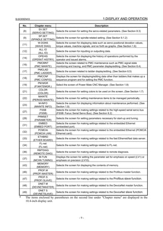
Operation selection keys, auxiliary menu
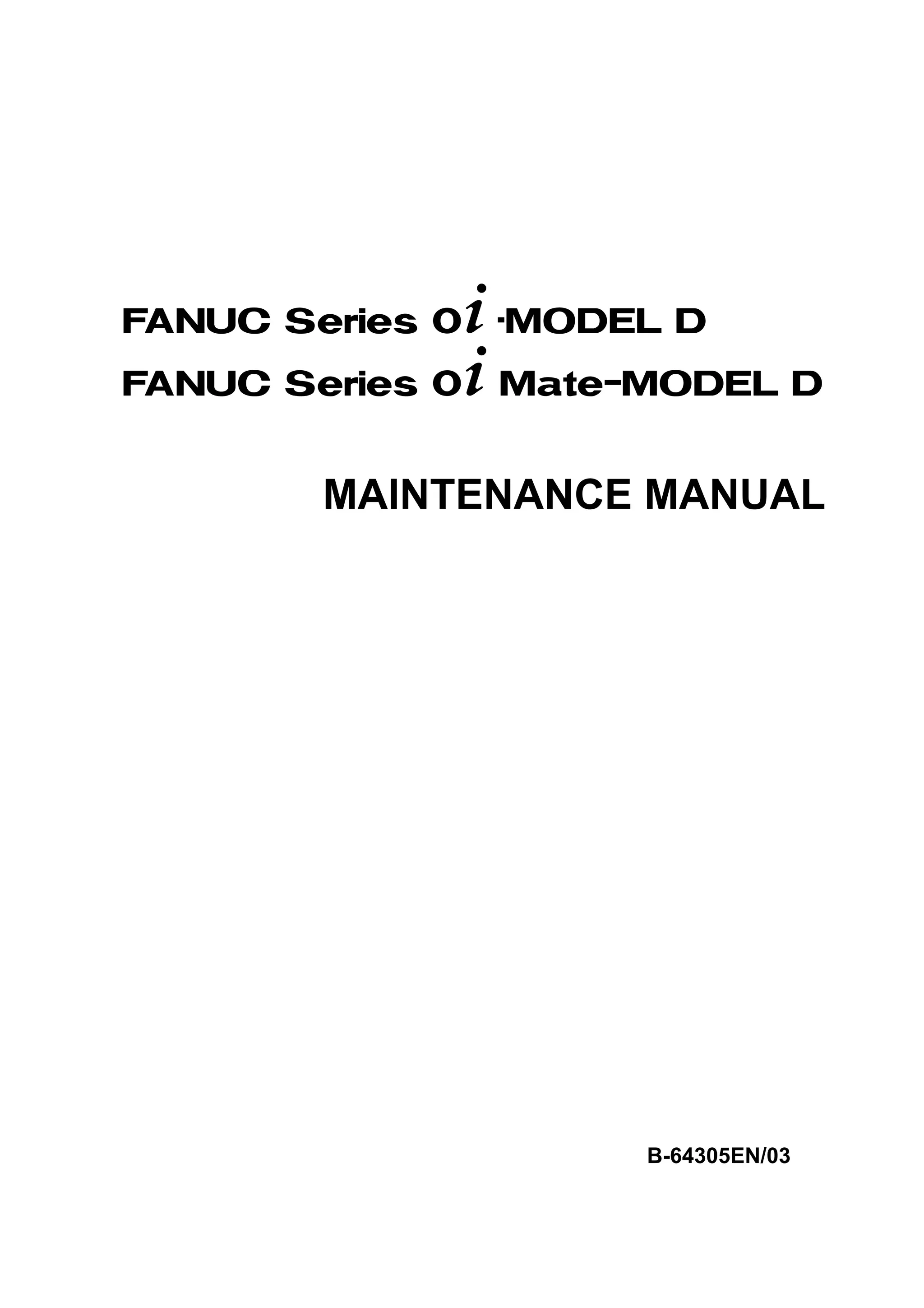
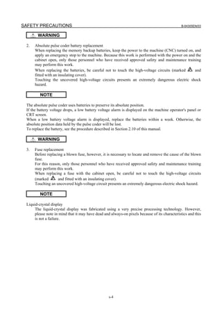
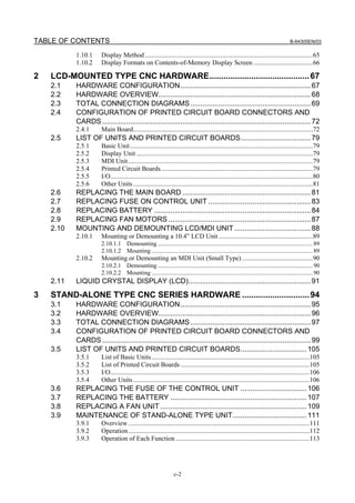
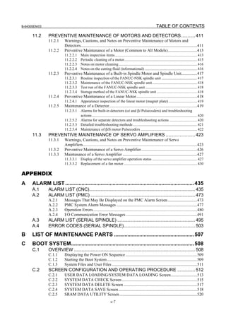
1.1.3 Function Keys
Function keys are provided to select the type of screen to be displayed. The following function keys are
provided on the MDI panel:
Press this key to display the position screen.
Press this key to display the program screen.
Press this key to display the offset/setting screen.
Press this key to display the system screen.
Press this key to display the message screen.
Press this key to display the graphics screen.
For the small MDI unit, press .
Press this key to display the custom screen 1 (conversational macro screen or C language
executor screen).
For the small MDI unit, press .
Press this key to display the custom screen 2 (conversational macro screen or C language
executor screen).
For the small MDI unit, there is no key that corresponds to this key.
1.1.4 Soft Keys
By pressing a soft key after a function key, the corresponding screen of the function can be displayed.
The chapter selection soft keys of each function are described below.
The four keys on the right-hand side are assigned to chapter selection soft keys. When multiple pages
are used for chapter selection soft keys, [+] is displayed on the continuous menu key (rightmost soft key).
Press the continuous menu key to switch between chapter selection soft keys.](https://image.slidesharecdn.com/fanuc0imaintenancemanual-140802043306-phpapp01/85/Fanuc-0i-maintenance-manual-CNC-milling-machine-21-320.jpg)
![1.DISPLAY AND OPERATION B-64305EN/03
- 4 -
NOTE
1 Press function keys to switch between screens that are used frequently.
2 Some soft keys are not displayed depending on the option configuration or
parameter setting.
For the 10.4-inch LCD display unit, when pressing other than function key indicates positional
display on the left side of the screen, the left half of the soft keys are shown below.
or
As for the soft key [MONITOR], refer to the Section III-12.8 in User’s Manual (Common to Lathe
System/Machining Center System).
Refer to the next page for other soft keys.
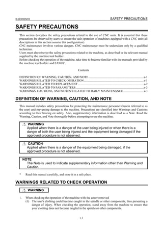
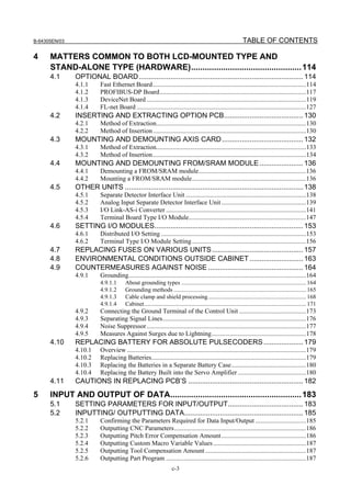
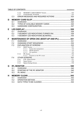
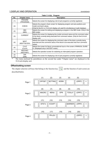
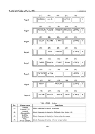
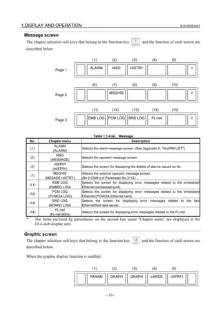
Position display screen
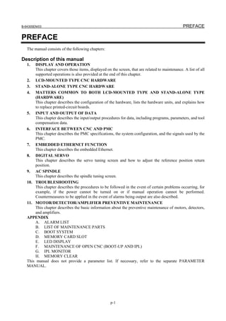
The chapter selection soft keys that belong to the function key and the function of each screen are
described below.
ABS REL ALL HNDL (OPRT)
Page 1
+
(1) (2) (3) (4) (5)
MONI (OPRT)
Page 2
+
(6) (7) (8) (9) (10)
Table 1.1.4 (a) Position display screen
No. Chapter menu Description
(1)
ABS
(ABSOLUTE)
Selects the absolute coordinate display screen.
(2)
REL
(RELATIVE)
Selects the relative coordinate display screen.
(3)
ALL
(ALL)
Selects the overall coordinate display screen.
(4)
HNDL
(HANDLE)
Selects the operation screen for manual handle operation.
(6)
MONI
(MONITOR)
Selects the screen for displaying the servo axis load meter, serial spindle load meter,
and speedometer.
(Bit 5 (OPM) of Parameter No.3111 = 1 / See Section 1.5)
* The items enclosed by parentheses on the second line under "Chapter menu" are displayed in the
10.4-inch display unit.](https://image.slidesharecdn.com/fanuc0imaintenancemanual-140802043306-phpapp01/85/Fanuc-0i-maintenance-manual-CNC-milling-machine-22-320.jpg)
![1.DISPLAY AND OPERATION B-64305EN/03
- 12 -
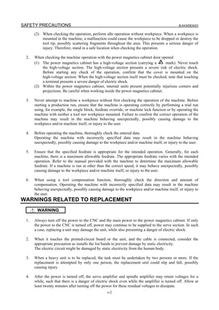
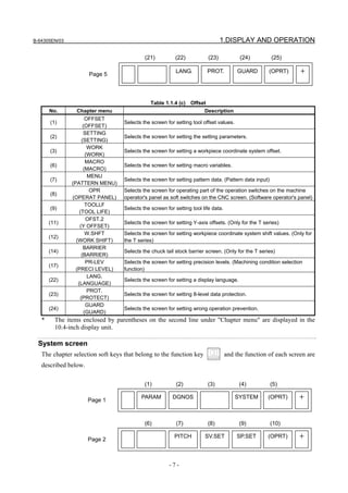
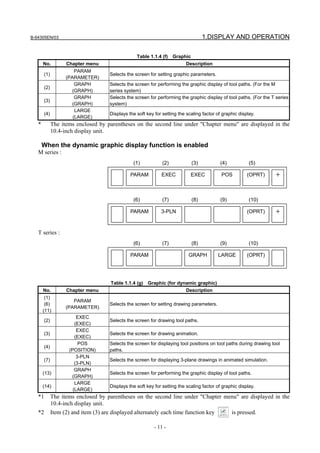
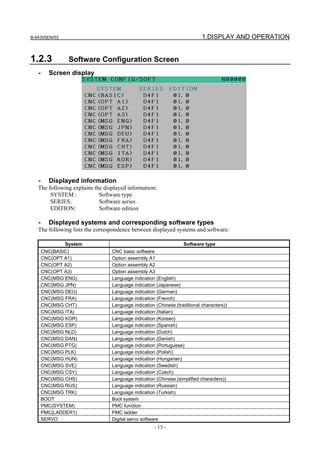
1.2 SYSTEM CONFIGURATION SCREEN
After the system has started normally, you can find the types of installed hardware and software types by
displaying a system configuration screen.
1.2.1 Display Method
1 Press the function key to display the screen for parameters and other data.
2 Pressing the soft key [SYSTEM] causes a system configuration screen to appear.
3 Two types of system configuration screen, the hardware configuration screen and software
configuration screen, are provided, and you can switch between these screens by using the
page keys.
When all information cannot be displayed on one page of the screen, you can switch to the next page
by using the keys.
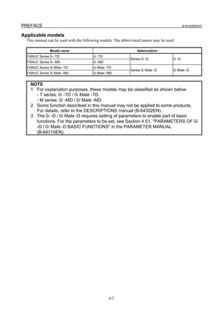
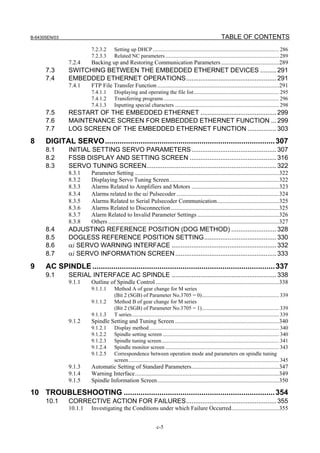
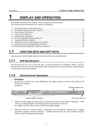
1.2.2 Hardware Configuration Screen
- Screen display
- Displayed information
The following explains the displayed information:
1. NAME
MAIN BOARD
• Displays information on the main board, and cards and modules on the main board.
OPTION BOARD
• Displays information on the board installed in the option slot.
DISPLAY
• Displays information on the display unit.
OTHERS
• Displays information on other components (such as an MDI and a basic unit).
2. ID-1, ID-2
• Displays the ID of each hardware component. For the details of the hardware ID, see section
2.5 or section 3.5.
3. SLOT
• Displays the number of the slot in which the option board is inserted.](https://image.slidesharecdn.com/fanuc0imaintenancemanual-140802043306-phpapp01/85/Fanuc-0i-maintenance-manual-CNC-milling-machine-30-320.jpg)
![1.DISPLAY AND OPERATION B-64305EN/03
- 14 -
System Software type
SPINDLE-1 Spindle 1
SPINDLE-2 Spindle 2
SPINDLE-3 Spindle 3
GRAPHIC Graphic function
MACRO EXE1 Macro executor 1
MACRO EXE2 Macro executor 2
MACRO EXE3 Macro executor 3
MACRO EXE4 Macro executor 4
MACRO EXE5 Macro executor 5
MACRO EXE6 Macro executor 6
MACRO MGI-M MANUAL GUIDE i (macro executor for M series)
MACRO MGI-T MANUAL GUIDE i (macro executor for T series)
MACRO MG0ME MANUAL GUIDE 0i (macro executor for M series execution macro)
MACRO MG0MC MANUAL GUIDE 0i (macro executor for M series conversation macro)
MACRO MG0TE MANUAL GUIDE 0i (macro executor for T series execution macro)
MACRO MG0TC MANUAL GUIDE 0i (macro executor for T series conversation macro)
MG0ILIB Library for MANUAL GUIDE 0i
MG0IAPL Application for MANUAL GUIDE 0i
MACRO TMITE TURN MATE i (macro executor)
TMILIB Library for TURN MATE i
TMIAPL Application for TURN MATE i
CEXELIB Library for C executor
CEXEAPL Application for C executor
MGILIB Library for MANUAL GUIDE i
MGIAPL Application for MANUAL GUIDE i
NET CONTROL Communication management software
EMBED ETHER Control software for embedded Ethernet function
PROFI SOFT Software for PROFIBUS function
PROFI MASTER Control software for PROFIBUS master function
PROFI SLAVE Control software for PROFIBUS slave function
ETHER/DTSVR Control software for Fast Data Server
DEVNT SOFT Software for DeviceNet function
FL-NET Software for FL-net function
FL-NET SOFT Control software for FL-net Server
- Display of macro executor
The series and edition are displayed for each number specified at the time of P-CODE macro
creation.
Up to 6 types of macro executor are displayed.
1.2.4 Outputting System Configuration Data
Data displayed on the system configuration screen can be output to an input/output device.
(1) Press function key .
(2) Press the EDIT switch on the machine operator's panel.
(3) Press soft key [SYSTEM] to display the system configuration screen.
(4) Press soft key [(OPRT)] and select soft key [F OUTPUT].
(5) Press soft key [EXCE].
(6) Data is output to the output device selected by parameter No. 0020.
Data is output to a file named SYS_CONF.TXT.](https://image.slidesharecdn.com/fanuc0imaintenancemanual-140802043306-phpapp01/85/Fanuc-0i-maintenance-manual-CNC-milling-machine-32-320.jpg)
![B-64305EN/03 1.DISPLAY AND OPERATION
- 15 -
1.3 DIAGNOSIS FUNCTION
1.3.1 Displaying Diagnosis Screen
(1) Press function key .
(2) Press soft key [DGNOS], then a diagnosis screen is displayed.
1.3.2 Contents Displayed
Causes when the machine does not travel in spite of giving a command
Diagnosis 0 CNC internal state 1
[Data type] Bit
NAME Internal state when "1" is displayed
INPOSITION CHECK In-position check is being done.
FEEDRATE OVERRIDE 0% Feedrate override is 0%.
JOG FEED OVERRIDE 0% Jog feedrate override is 0%.
INTER/START LOCK ON Interlock/start lock is on.
SPEED ARRIVAL ON The system is waiting for the speed arrival signal to turn on.
WAIT REVOLUTION The system is waiting for the spindle one-rotation signal in
threading.
STOP POSITION OCDER The system is waiting for the rotation of the position coder in spindle
feed per revolution.
FEED STOP A feed stop was made.
Diagnosis 8 CNC internal state 2
[Data type] Bit
NAME Internal state when "1" is displayed
FOREGROUND READING Data is being input in the foreground.
BACKGROUND READING Data is being input in the background.
Reader/puncher interface output state
Diagnosis 10 Reader/puncher interface output state
When data is being output through the reader/puncher interface, "1" is indicated.
State of TH alarm
Diagnosis 30 TH alarm character count (foreground edit)
[Data type] 2-word
The position where the TH alarm occurred in foreground input is indicated by the number
of characters from the beginning of the block.
Diagnosis 31 TH alarm character code (foreground edit)
[Data type] Bit
The character code of the character at which the TH alarm occurred in foreground input is
indicated.
Diagnosis 32 TH alarm character count (background edit)
[Data type] 2-word
The position where the TH alarm occurred in background input is indicated by the
number of characters from the beginning of the block.](https://image.slidesharecdn.com/fanuc0imaintenancemanual-140802043306-phpapp01/85/Fanuc-0i-maintenance-manual-CNC-milling-machine-33-320.jpg)
![1.DISPLAY AND OPERATION B-64305EN/03
- 16 -
Diagnosis 33 TH alarm character code (background edit)
[Data type] Bit
The character code of the character at which the TH alarm occurred in background input
is indicated.
Display language of the CNC screen
Diagnosis 43 Number of the current display language of the CNC screen
[Data type] Byte
The number of the current display language of the CNC screen is indicated.
The correspondence between languages and numbers is show below.
0 : English
1 : Japanese
2 : German
3 : French
4 : Chinese (traditional characters)
5 : Italian
6 : Korean
7 : Spanish
8 : Dutch
9 : Danish
10 : Portuguese
11 : Polish
12 : Hungarian
13 : Swedish
14 : Czech
15 : Chinese (simplified characters)
16 : Russian
17 : Turkish
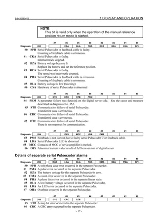
Details of serial Pulsecoder
#7 #6 #5 #4 #3 #2 #1 #0
Diagnosis 200 OVL LV OVC HCA HVA DCA FBA OFA
#0 OFA Overflow alarm
#1 FBA Disconnection alarm
#2 DCA Discharge alarm
#3 HVA Overvoltage alarm
#4 HCA Abnormal current alarm
#5 OVC Over current alarm
#6 LV Insufficient voltage alarm
#7 OVL Overload alarm
#7 #6 #5 #4 #3 #2 #1 #0
Diagnosis 201 ALD PCR EXP
#4 EXP
#7 ALD
ALD EXP Description
0 - Motor overheat
Overload alarm
1 - Amplifier overheat
1 0 Built-in Pulsecoder (hard)
1 1 Disconnection of separated type Pulsecoder (hard)Disconnection alarm
0 0 Disconnection of Pulsecoder (software)
#6 PCR The one-rotation signal of the position detector was caught before a manual reference
position return is performed. Since the manual reference position return grid was
established, a manual reference position return is enabled.](https://image.slidesharecdn.com/fanuc0imaintenancemanual-140802043306-phpapp01/85/Fanuc-0i-maintenance-manual-CNC-milling-machine-34-320.jpg)
![1.DISPLAY AND OPERATION B-64305EN/03
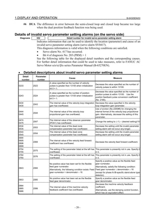
- 18 -
#7 DTE A data error occurred in the separate Pulsecoder.
Details of invalid servo parameter alarms (on the CNC side)
When servo alarm SV0417 is issued, and diagnosis No. 203#4 = 0, its cause is indicated.
When diagnosis No. 203#4 = 1, see diagnosis No. 352.
#7 #6 #5 #4 #3 #2 #1 #0
Diagnosis 280 DIR PLS PLC MOT
#0 MOT The motor type specified in parameter No. 2020 falls outside the predetermined range.
#2 PLC The number of velocity feedback pulses per motor revolution, specified in parameter No.
2023, is zero or less. The value is invalid.
#3 PLS The number of position feedback pulses per motor revolution, specified in parameter No.
2024, is zero or less. The value is invalid.
#4 DIR The wrong direction of rotation for the motor is specified in parameter No. 2022 (the
value is other than 111 or -111).
Position error amount
Diagnosis 300 Individual-axis positional deviation difference displayed in detection units
Feed rate [mm/min] × 100 1
Position error =
60 × servo loop gain [1/sec]
×
Detection unit
Machine position
Diagnosis 301 Distance from reference position of an axis in detection unit
Distance from the end of the deceleration dog to the first grid point
Diagnosis 302 Distance from the end of the deceleration dog to the first grid point
[Data type] Real axis
[Unit of data] Machine unit
[Valid data range] 0 to ±99999999
NOTE
For the reference position setting without a dog, the distance from
the beginning of the reference position setting without a dog to the
first grid point is assumed.
Reference counter
Diagnosis 304 Reference counter amount in each axis
[Data type] 2-word axis
[Unit of data] Detection unit
[Valid data range] –99999999 to 99999999
Angular axis control / Machine coordinates in the Cartesian coordinate
system
Diagnosis 306 Machine coordinates on the angular axis in the Cartesian coordinate system
Diagnosis 307 Machine coordinates on the perpendicular axis in the Cartesian coordinate system
[Data type] Real number
[Unit of data] Machine unit
Machine coordinates in the Cartesian coordinate system are displayed in arbitrary angular
axis control. Bit 7 (ADG) of parameter No. 8201 can be used to change the display order.](https://image.slidesharecdn.com/fanuc0imaintenancemanual-140802043306-phpapp01/85/Fanuc-0i-maintenance-manual-CNC-milling-machine-36-320.jpg)
![B-64305EN/03 1.DISPLAY AND OPERATION
- 19 -
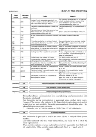
Motor temperature information
Diagnosis 308 Servo motor temperature (°C)
[Data type] Byte axis
[Unit of data] °C
[Valid data range] 0 to 255
The temperature of the coil of the servo motor is indicated. When the temperature
reaches 140°C, a motor overheat alarm is issued.
Diagnosis 309 Pulsecoder temperature (°C)
[Data type] 2-word axis
[Unit of data] °C
[Valid data range] 0 to 255
The temperature of the printed circuit board in the Pulsecoder is indicated. When the
temperature reaches 100°C (approximately 85°C for the temperature of atmosphere in the
Pulsecoder), a motor overheat alarm is issued.
NOTE
1 Temperature information has the following error:
• 50°C to 160°C ±5°C
• 160°C to 180°C ±10°C
2 The temperature at which an overheat alarm is issued has an error
of up to 5°C.
Cause that sets bit 4 (APZ) of parameter No. 1815 to 0
You can find the cause that sets bit 4 (APZ) of parameter No. 1815 to 0 by checking diagnosis Nos. 310
and 311.
Once diagnosis No. 310 or 311 is set to 1, this setting is kept unchanged until the zero point of the
absolute position detector of the corresponding axis is set again. Possible causes that set APZ to 0 are as
follows:
#7 #6 #5 #4 #3 #2 #1 #0
Diagnosis 310 DTH ALP NOF BZ2 BZ1 PR2 PR1
#0 PR1 One of the following parameters was changed:
No.1803#7, No.1815#1, No.1820, No.1821, No.1822, No.1823, No.1850, No.1874,
No.1875, No.2022, No.2084, No.2085
#1 PR2 Bit 1 (ATS) of parameter No. 8303 was changed. Alternatively, when bit 7 (SMA) of
parameter No. 8302 was set to 1, APZ of the axis to be synchronized together was set to
0.
#2 BZ1 A battery voltage of 0 V was detected. (Inductosyn)
#3 BZ2 A battery voltage of 0 V was detected. (Separate position detector)
#4 NOF The Inductosyn did not output offset data.
#5 ALP The zero point was set by MDI when the αi pulse coder had not rotate one or more turns.
#6 DTH An axis detach operation was performed by the controlled-axis detach signal DTCH
<G0124> or by setting bit 7 (RMV) of parameter No. 0012.
#7 #6 #5 #4 #3 #2 #1 #0
Diagnosis 311 DUA XBZ GSG AL4 AL3 AL2 AL1
#0 AL1 An SV alarm (SV0301 to SV0305) was issued.
#1 AL2 Broken-wire alarm SV0445 or SV0447 was detected.
#2 AL3 A battery voltage of 0 V was detected. (Serial Pulsecoder)
#3 AL4 Rotation count abnormality alarm RCAL was detected.
#4 GSG The status of broken-wire alarm ignore signal NDCAL <0G202> changed from 1 to 0.
#5 XBZ A battery voltage of 0 V or a count error was detected. (Separate serial position
detector)](https://image.slidesharecdn.com/fanuc0imaintenancemanual-140802043306-phpapp01/85/Fanuc-0i-maintenance-manual-CNC-milling-machine-37-320.jpg)
![1.DISPLAY AND OPERATION B-64305EN/03
- 22 -
Therefore, check the bits sequentially from the lowest bit to find the first bit that is set to
0. This bit indicates that the corresponding processing could not be completed and so
the V ready-off alarm was caused.
SRDY DRDY INTL CRDY
#15 #14 #13 #12 #11 #10 #09 #08
*ESP
#07 #06 #05 #04 #03 #02 #01 #00
#06 *ESP Converter emergency stop state released
#10 CRDY Converter ready
#12 INTL DB relay released
#13 DRDY Amplifier ready (amplifier)
#14 SRDY Amplifier ready (software)
* For details, refer to a relevant manual on FANUC SERVO MOTOR αi series.
Diagnosis 359 Communication alarm neglect counter (built-in type)
The diagnosis information is the same as that of diagnosis No. 355.
See the descriptions in diagnoses No.355 to 357.
Diagnosis 360 Cumulative value of specified pulses (NC)
[Data type] 2-word
[Unit of data] Detection unit
[Valid data range] -99999999 to 99999999
Cumulative value of move commands distributed from the CNC since power-on is
indicated.
Diagnosis 361 Compensation pulses (NC)
[Data type] 2-word
[Unit of data] Detection unit
[Valid data range] -99999999 to 99999999
Cumulative value of compensation pulses (backlash compensation, pitch error
compensation, and so on) distributed from the CNC since power-on is indicated.
Diagnosis 362 Cumulative value of specified pulses (SV)
[Data type] 2-word
[Unit of data] Detection unit
[Valid data range] -99999999 to 99999999
Cumulative value of move pulses and compensation pulses received by the servo system
since power-on is indicated.
Diagnosis 363 Cumulative feedback (SV)
[Data type] 2-word
[Unit of data] Detection unit
[Valid data range] -99999999 to 99999999
Cumulative value of positional feedback pulses the servo system received from the pulse
coder since power-on is indicated.
Diagnosis data related to the Inductosyn absolute position detector
Diagnosis 380 Difference between the absolute position of the motor and offset data
[Data type] 2-word axis
[Unit of data] Detection unit
M (absolute position of the motor)-S (offset data)
λ (pitch interval)](https://image.slidesharecdn.com/fanuc0imaintenancemanual-140802043306-phpapp01/85/Fanuc-0i-maintenance-manual-CNC-milling-machine-40-320.jpg)
![B-64305EN/03 1.DISPLAY AND OPERATION
- 23 -
The remainder resulting from the division is displayed.
Diagnosis 381 Offset data from the Inductosyn
[Data type] 2-word axis
[Unit of data] Detection unit
Off set data is displayed when CNC calculates the machine position.
Diagnosis data related to the serial spindles
#7 #6 #5 #4 #3 #2 #1 #0
Diagnosis 400 LNK
#7 LNK Communication with the spindle control side has been established.
Diagnosis 403 Temperature of spindle motor
[Data type] Byte spindle
[Unit of data] °C
[Valid data range] 0 to 255
The temperature of the winding of the spindle motor is indicated.
This information can be used to determine the overheat alarm of the spindle.
(The temperature that causes an overheat alarm varies from motor to motor.)
NOTE
1 Temperature information has the following error:
• 50°C to 160°C ±5°C
• 160°C to 180°C±10°C
2 The indicated temperature and the temperature causing an
overheat alarm have the following error:
• For lower than 160°C 5°C maximum
• For 160 to 180°C 10°C maximum
#7 #6 #5 #4 #3 #2 #1 #0
Diagnosis 408 SSA SCA CME CER SNE FRE CRE
#0 CRE A CRC error occurred (warning).
#1 FRE A framing error occurred (warning).
#2 SNE The sender or receiver is not correct.
#3 CER An abnormality occurred during reception.
#4 CME No response was returned during automatic scanning.
#5 SCA A communication alarm was issued on the spindle amplifier side.
#7 SSA A system alarm was issued on the spindle amplifier side.
(The above conditions are major causes of alarm SP0749. These conditions are caused
mainly by noise, a broken wire, a momentary failure of power, and so on.)
Diagnosis 410 Spindle load meter indication [%]
[Data type] Word spindle
[Unit of data] %
Diagnosis 411 Spindle speed meter indication [min
-1
]
[Data type] Word spindle
[Unit of data] min-1
Diagnosis 417 Spindle position coder feedback information
[Data type] 2-word spindle
[Unit of data] Detection unit](https://image.slidesharecdn.com/fanuc0imaintenancemanual-140802043306-phpapp01/85/Fanuc-0i-maintenance-manual-CNC-milling-machine-41-320.jpg)
![1.DISPLAY AND OPERATION B-64305EN/03
- 24 -
Diagnosis 418 Positional deviation of spindle in position loop mode
[Data type] 2-word spindle
[Unit of data] Detection unit
Diagnosis 425 Spindle synchronization error
[Data type] 2-word spindle
[Unit of data] Detection unit
When the spindles are in synchronization mode, the absolute value of the synchronization
error when each spindle is set as the slave axis is indicated.
Diagnosis 445 Spindle position data
[Data type] Word spindle
[Unit of data] Pulse
[Valid data range] 0 to 4095
For the serial spindle, position coder signal pulse data from the one-rotation signal is
indicated as the position data of the spindle.
This data is valid when bit 1 of parameter No. 3117 is set to 1.
To display spindle position data, spindle orientation must be performed once.
Diagnosis data related to rigid tapping
Diagnosis 450 Spindle position error during rigid tapping
[Data type] 2-word spindle
[Unit of data] Detection unit
Diagnosis 451 Spindle distribution during rigid tapping
[Data type] 2-word spindle
[Unit of data] Detection unit
Diagnosis 452
Difference in error amount between spindle and tapping axis during rigid tapping
(momentary value)
[Data type] 2-word spindle
[Unit of data] %
Diagnosis 453
Difference in error amount between spindle and tapping axis during rigid tapping (maximum
value)
[Data type] 2-word spindle
[Unit of data] %
Diagnosis 454 Accumulated spindle distribution during rigid tapping (cumulative value)
[Data type] 2-word spindle
[Unit of data] Detection unit
Diagnosis 455 Difference in spindle-converted move command during rigid tapping (momentary value)
[Data type] 2-word spindle
[Unit of data] Detection unit
Diagnosis 456 Difference in spindle-converted positional deviation during rigid tapping (momentary value)
[Data type] 2-word spindle
[Unit of data] Detection unit
Diagnosis 457 Width of synchronization error during rigid tapping (maximum value)
[Data type] 2-word spindle
[Unit of data] Detection unit](https://image.slidesharecdn.com/fanuc0imaintenancemanual-140802043306-phpapp01/85/Fanuc-0i-maintenance-manual-CNC-milling-machine-42-320.jpg)
![B-64305EN/03 1.DISPLAY AND OPERATION
- 25 -
Diagnosis 458 Tapping axis distribution amount during rigid tapping (cumulative value)
[Data type] 2-word spindle
[Unit of data] Detection unit
Diagnosis 459 Selected spindle number during rigid tapping
[Data type] 2-word path
Diagnosis 460 Difference in spindle-converted move command during rigid tapping (maximum value)
[Data type] 2-word spindle
[Unit of data] Detection unit
Diagnosis 461 Difference in spindle-converted machine position during rigid tapping (momentary value)
[Data type] 2-word spindle
[Unit of data] Detection unit
Diagnosis 462 Difference in spindle-converted machine position during rigid tapping (maximum value)
[Data type] 2-word spindle
[Unit of data] Detection unit
Diagnosis data related to the small-hole peck drilling cycle (M series)
Diagnosis 520
Total number of times a retraction operation has been performed during drilling since G83
was specified
Diagnosis 521
Total number of times a retraction operation has been performed in response to the
reception of the overload torque detection signal during drilling since G83 was specified
The total numbers of times output in Nos.520 and 521 are cleared to zero by a G83
command issued after the small-hole peck drilling cycle mode is entered.
Diagnosis 522
Coordinate value of the drilling axis at which retraction operation starts (least input
increment)
Diagnosis 523
Difference between the coordinate value of the drilling axis at which the previous retraction
operation started and the coordinate value of the drilling axis at which the current retraction
operation starts (least input increment: previous value minus current value)
Diagnosis data related to the dual position feedback function
Diagnosis 550 Closed loop error
[Data type] 2-word axis
[Unit of data] Detection unit
[Valid data range] -99999999 to +99999999
Diagnosis 551 Semi-closed loop error
[Data type] 2-word axis
[Unit of data] Detection unit
[Valid data range] -99999999 to +99999999
Diagnosis 552 Error between semi-closed and closed loops
[Data type] Word axis
[Unit of data] Detection unit
[Valid data range] -32768 to +32767
Diagnosis 553 Amount of dual position compensation
[Data type] 2-word axis](https://image.slidesharecdn.com/fanuc0imaintenancemanual-140802043306-phpapp01/85/Fanuc-0i-maintenance-manual-CNC-milling-machine-43-320.jpg)
![1.DISPLAY AND OPERATION B-64305EN/03
- 26 -
[Unit of data] Detection unit
[Valid data range] -99999999 to +99999999
The data items displayed on the diagnosis screen are obtained at the following positions:
Semi-closed loop
error (No. 551)
Σ Kp Speed
control
Machine
Conversion
coefficients
× Time
constant
Σ
Closed loop
error (No. 550)
Error between
semi-closed and
closed loops (No.
552)
Amount of dual
position
compensation (No.
553)
Motor
Servo amplifier
(Parameters No. 2078 and 2079)
(Parameter No. 2080)
+
--
+ +
+
-
+
+
+
+
-
Command
Ps
Automatic alteration of tool position compensation (T series)
Diagnosis 0560 Manual tool compensation state number
[Data type] Byte
[Unit of data] None
[Valid data range] 0 to 255
When incomplete operation was performed in manual tool compensation, one of the
following numbers is used for notification.
0 : Manual tool compensation was completed normally.
1 : The data of T code command falls outside the allowable range.
2 : The offset value falls outside the range.
3 : The offset number falls outside the range.
4 : Automatic operation or axis movement is being performed in the CNC.
5 : The CNC is in the tool-nose radius compensation mode.
6 : The CNC is in a mode other than the JOG mode, HNDL (INC) mode, and REF
mode.
7 : A CNC parameter is illegal.
State of high-speed HRV current control
#7 #6 #5 #4 #3 #2 #1 #0
Diagnosis 700 HOK HON
[Data type] Bit axis
The state of high-speed HRV current control is displayed.
#0 HON The motor is controlled in the high-speed HRV current control mode.
#1 HOK This bit is set to 1 when high-speed HRV current control is enabled.
High-speed HRV current control is enabled when the following conditions are satisfied:
• Bit 0 (HR3) of parameter No. 2013 is set to 1.
• Servo software, servo modules, and servo amplifiers suitable for high-speed HRV
current control are used.](https://image.slidesharecdn.com/fanuc0imaintenancemanual-140802043306-phpapp01/85/Fanuc-0i-maintenance-manual-CNC-milling-machine-44-320.jpg)
![B-64305EN/03 1.DISPLAY AND OPERATION
- 27 -
• When a separate detector interface unit is used, the separate detector interface unit is
suitable for high-speed HRV current control.
Spindle error and warning states
Diagnosis 710 Spindle error state
[Data type] Word spindle
Diagnosis 712 Spindle warning state
[Data type] Word spindle
When an error (yellow LED ON + error number indication) or a warning occurs in a
spindle amplifier (SP), the number is indicated on the diagnosis screen.
If neither error nor warning occurs, 0 is indicated.
For spindle errors, refer to "FANUC SERVO MOTOR αi series Maintenance Manual"
(B-65285EN).
For warnings, see Subsection 9.1.4, "Spindle Warning Interface" in this manual.
OVC level
Diagnosis 750 OVC level
[Data type] Word axis
[Unit of data] %
The proportion of soft thermal (OVC) in the alarm issuance level is indicated.
・ Reset state
#7 #6 #5 #4 #3 #2 #1 #0
Diagnosis 1010 RST ERS RRW ESP
[Data type] Bit
#0 ESP In the emergency stop state
#1 RRW Reset & rewind signal set to 1.
#2 ERS External reset signal set to 1.
#3 RST RESET key pressed.
・ Cause that turned the cycle start LED off
#7 #6 #5 #4 #3 #2 #1 #0
Diagnosis 1011 HLD STP MOD ALM RST ERS RRW ESP
[Data type] Bit
The cause that turned the cycle start LED off is indicated.
#0 ESP In the emergency stop state
#1 RRW Reset & rewind signal
#2 ERS External reset signal
#3 RST Reset key
#4 ALM Alarm
#5 MOD Change to another mode
#6 STP Single block stop
#7 HLD Feed hold
Automatic data backup
#7 #6 #5 #4 #3 #2 #1 #0
Diagnosis 1016 ANG ACM DT3 DT2 DT1 AEX
[Data type] Bit
The execution state of backup is indicated.
#0 AEX Automatic data backup is being performed.
#1 DT1 Data 1 was updated in the previous backup.](https://image.slidesharecdn.com/fanuc0imaintenancemanual-140802043306-phpapp01/85/Fanuc-0i-maintenance-manual-CNC-milling-machine-45-320.jpg)
![1.DISPLAY AND OPERATION B-64305EN/03
- 28 -
#2 DT2 Data 2 was updated in the previous backup.
#3 DT3 Data 3 was updated in the previous backup.
#6 ACM Automatic data backup was performed.
#7 ANG An error occurred in automatic data backup.
Spindle revolution number history function
Diagnosis 1520 Spindle total revolution number 1
Diagnosis 1521 Spindle total revolution number 2
[Data type] 2-word spindle
[Unit of data] 1000 min-1
[Valid data range] 0 to 999999999
The number of revolutions of the spindle is counted and the total number of revolutions is
indicated.
Detector battery exhaustion
#7 #6 #5 #4 #3 #2 #1 #0
Diagnosis 3019 EXP INP ABP
[Data type] Bit axis
If a detector battery low alarm is issued, the cause can be checked.
#3 ABP The battery of the A/B phase is low.
#4 INP The battery of the serial pulse coder (built-in position detector) is low.
#5 EXP The battery of the separate detector of serial type is low.
Diagnosis data related to axis synchronous control
Diagnosis 3500 Synchronization error amount
[Data type] 2-word axis
[Unit of data] Detection unit
[Valid data range] −99999999 to +99999999
The difference in position (synchronization error amount) between the master axis and
slave axis is indicated. This data is indicated for the slave axis.
Diagnosis 3501 Synchronization error compensation value
[Data type] 2-word axis
[Unit of data] Detection unit
[Valid data range] −99999999 to +99999999
Cumulative value of compensation pulses (synchronization error compensation value)
output to the slave axis is indicated. This data is indicated for the slave axis.
Diagnosis data related to synchronous/composite control (T series)
Diagnosis 3502 Indication of synchronization error amount for each axis
[Data type] 2-word axis
[Unit of data] Detection unit
[Valid data range] −99999999 to +99999999
When synchronization deviation is detected (SERx of parameter No. 8162 is set to 1), the
positional deviation difference of the slave axis from the master axis is indicated.
The positional deviation difference is:
(Positional deviation of master axis)
± (positional deviation of slave axis)
↑
+ when mirror image is applied to synchronization command
− when mirror image is not applied to synchronization command](https://image.slidesharecdn.com/fanuc0imaintenancemanual-140802043306-phpapp01/85/Fanuc-0i-maintenance-manual-CNC-milling-machine-46-320.jpg)
![B-64305EN/03 1.DISPLAY AND OPERATION
- 29 -
Diagnosis data related to linear scale with absolute address reference marks
Diagnosis 3545 Linear scale with absolute address reference marks Measurement point 1
Diagnosis 3546 Linear scale with absolute address reference marks Measurement point 2
Diagnosis 3547 Linear scale with absolute address reference marks Measurement point 3
Diagnosis 3548 Linear scale with absolute address reference marks Measurement point 4
[Data type] 2-word axis
[Unit of data] Detection unit
[Valid data range] -999999999 to 999999999
Diagnosis 3549 Linear scale with absolute address reference marks Status display
Diagnosis 3550 Linear scale with absolute address reference marks Scale value
[Data type] 2-word axis
[Unit of data] Detection unit
[Valid data range] -999999999 to 999999999
Diagnosis 3551 Linear scale with absolute address reference marks Scale value (High)
[Data type] 2-word axis
[Unit of data] Detection unit
[Valid data range] -999 to 999
Linear scale with absolute address reference marks
Scale value = Diagnosis No.3551 × 1,000,000,000 + Diagnosis No.3550](https://image.slidesharecdn.com/fanuc0imaintenancemanual-140802043306-phpapp01/85/Fanuc-0i-maintenance-manual-CNC-milling-machine-47-320.jpg)
![1.DISPLAY AND OPERATION B-64305EN/03
- 32 -
Example 2)
When a parameter is entered
Example 3)
When a parameter is output to an external input/output device
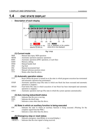
(10) Tool post name
The number of a path whose status is indicated is displayed.
HEAD1 : Indicates that the status being indicated is for path 1.
Other names can be used depending on the settings of parameters 3141 to 3147. The path
name is displayed at the position where (8) is now displayed. When a program is being
edited or operated, (8) is displayed depending on the situation.
1.5 OPERATING MONITOR
Load meter of the servo axis and the serial spindle and the speed meter can be displayed.
1.5.1 Display Method
1 Set a parameter to display operating monitor. (Bit 5 (OPM) of parameter No.3111)
2 Press the key to display the position display screen.
3 Press continuous menu key , then soft key [MONITOR] is displayed.
4 Press the soft key [MONITOR], then the operating monitor screen is displayed.](https://image.slidesharecdn.com/fanuc0imaintenancemanual-140802043306-phpapp01/85/Fanuc-0i-maintenance-manual-CNC-milling-machine-50-320.jpg)
![B-64305EN/03 1.DISPLAY AND OPERATION
- 33 -
CAUTION
1 The bar graph for the load meter shows load up to 200%.
2 The bar graph for the speed meter shows the ratio of the current spindle speed
to the maximum spindle speed (100%). Although the speed meter normally
indicates the speed of the spindle motor, it can also be used to indicate the
speed of the spindle by setting bit 6 (OPS) of parameter 3111 to 1.
1.5.2 Parameters
#7 #6 #5 #4 #3 #2 #1 #0
3111 OPS OPM
[Input type] Setting input
[Data type] Bit path
#5 OPM Operating monitor
0: Not displayed
1: Displayed
#6 OPS The speedometer on the operating monitor screen indicates:
0: Spindle motor speed
1: Spindle speed
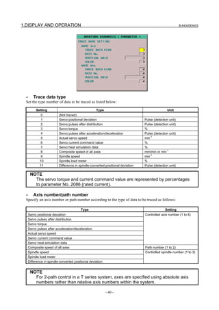
1.6 WAVEFORM DIAGNOSIS DISPLAY
The waveform diagnosis display function traces values of data such as servo positional deviation amount,
torque, and machine signals and plots and displays a graph representing changes in the traced data. This
function facilitates servo motor and spindle motor adjustment and fault location when trouble has
occurred.
The waveform diagnosis function can trace the following data:
(1) Servo-related data
• Positional deviation amount](https://image.slidesharecdn.com/fanuc0imaintenancemanual-140802043306-phpapp01/85/Fanuc-0i-maintenance-manual-CNC-milling-machine-51-320.jpg)
![1.DISPLAY AND OPERATION B-64305EN/03
- 34 -
• Pulse amount after distribution
• Torque amount
• Pulse amount after acceleration/deceleration
• Actual speed
• Current command value
• Heat simulation data
• Composite speed of all axes
(2) Spindle-related data
• Speed of each spindle
• Load meter
• Spindle-converted positional deviation difference
(3) Machine signal
• ON/OFF state of the external I/O signal specified by a signal address
Up to four servo and spindle data items or up to 32 signals can be traced at the same time.
Data can be traced under the following three conditions:
(1) Data is acquired at any point of time.
(2) Data immediately after a specified event is acquired.
(3) Data immediately before a specified event is acquired.
In condition (3), the time to end tracing can be delayed by a specified time. This allows data before and
after the occurrence of an event can be acquired.
Traced data can be output to an external input/output device.
1.6.1 Waveform Diagnosis Graph Screen
1 Press the function key .
2 Pressing the [WAVE DIAG] soft key and [WAVE GRAPH] soft key displays the following screen.
3 Pressing the [(OPRT)] soft key displays the following operation selection soft keys:](https://image.slidesharecdn.com/fanuc0imaintenancemanual-140802043306-phpapp01/85/Fanuc-0i-maintenance-manual-CNC-milling-machine-52-320.jpg)
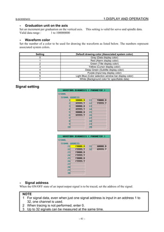
![B-64305EN/03 1.DISPLAY AND OPERATION
- 35 -
- Servo and spindle data
Each waveform is drawn in a specified color. The numbers and colors of the first and second
waveforms are indicated in the upper left part, and the numbers and colors of the third and fourth
waveforms are indicated in the upper right part.
- I/O signals
When waveforms for servo and spindle data are drawn with one on another, up to four waveforms are
drawn on the part below the center of the screen.
In this case, the addresses of the plotted signals are indicated in the second column on the left side.
When only signal data is displayed, up to nine signals are plotted in the entire screen.
The addresses of the plotted signals are indicated in the first column on the left side.
- When displayed I/O signal data is updated
Displayed I/O signal data is updated when:
(1) The waveform diagnosis graph screen is displayed for the first time after power-on.
(2) Trace operation ends.
The displayed I/O signal data, therefore, is not updated when signal addresses are changed on the
waveform diagnosis parameter screen. To reflect the changes, either of the above operations is required.
1.6.2 Waveform Diagnosis Parameter Screen
Display
1 Press the function key .
2 Press the soft key [WAVE DIAG].
3 Pressing the soft key [WAVE PARAM] displays the waveform diagnosis parameter screen.
Editing
1 Follow the steps explained in "Display" to display the screen.](https://image.slidesharecdn.com/fanuc0imaintenancemanual-140802043306-phpapp01/85/Fanuc-0i-maintenance-manual-CNC-milling-machine-53-320.jpg)
![1.DISPLAY AND OPERATION B-64305EN/03
- 36 -
2 Pressing the cursor keys moves the cursor on the screen.
3 Press numeric keys, then press the MDI key or [INPUT] soft key to set the entered value.
4 Press the [(OPRT)] soft key to display the following operation selection soft keys:
Pressing continuous menu key [+] displays the following soft keys:
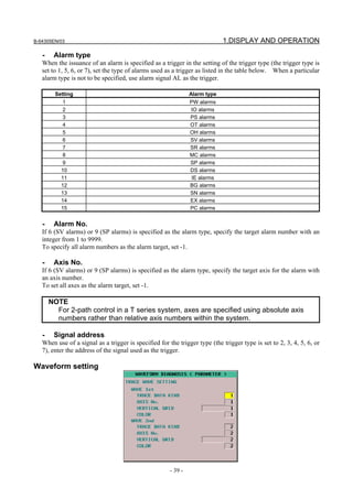
Pressing [TRACE] soft key displays the trace setting screen of the waveform diagnosis parameter
screen.
Pressing [WAVE] soft key displays the waveform setting screen of the waveform diagnosis
parameter screen.
Pressing [SIGNAL] soft key displays the signal setting screen of the waveform diagnosis parameter
screen.
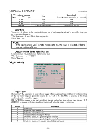
Trace setting
- Trace condition
One of the following three trace conditions can be selected to start and end tracing:](https://image.slidesharecdn.com/fanuc0imaintenancemanual-140802043306-phpapp01/85/Fanuc-0i-maintenance-manual-CNC-milling-machine-54-320.jpg)
![B-64305EN/03 1.DISPLAY AND OPERATION
- 37 -
Type 1 (1: JUST)
Data is traced only for a specified period of time immediately after the [TRACE] soft key is pressed.
[TRACE] pressed
Time
Trace time
Type 2 (2: AFTER)
When the [TRACE] soft key has been pressed, data is traced only for a specified period of time
immediately after a specified trigger event occurs.
[TRACE] pressed
Time
Trace time
Event occurs
Type 3 (3: BEFORE)
When the [TRACE] soft key has been pressed, data is traced only for a specified period of time
immediately before a specified trigger event occurs.
[TRACE] pressed
Time
Trace time
Event occurs
Setting Trace condition
1 Type 1
2 Type 2
3 Type 3
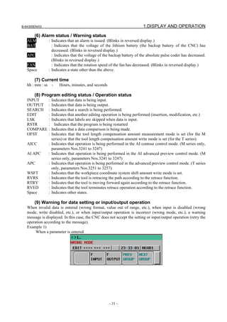
- Sampling cycle
Set the sampling cycle period for waveforms and the sampling cycle for signals as follows:
Type Setting
Waveform Multiple of 2 ranging from 2 ms to 4096 ms
Signal Multiple of 2 ranging from 2 ms to 4096 ms
- Trace time
Set the period for tracing data.
The trace time specifies a period of time during which tracing is to be performed for waveforms and
signals. If the trace period is insufficient, increase the sampling cycle, or decrease the measurement
items.
Approximately 32700 points of data can be traced. One point is used for each sampling cycle of one
channel. For signal measurement, one channel is used regardless of the number of signals measured at
the same time.
When one channel of waveform is traced with a sampling cycle of 4 ms, tracing can be performed for 130
s.
When one channel of waveform is traced with a sampling cycle of 4096 ms, tracing can be performed for
37 hours.
Valid data range: 2 to 133939200
Unit of data: msec
Example of maximum trace time determined by the sampling cycle and the number of channels](https://image.slidesharecdn.com/fanuc0imaintenancemanual-140802043306-phpapp01/85/Fanuc-0i-maintenance-manual-CNC-milling-machine-55-320.jpg)
![1.DISPLAY AND OPERATION B-64305EN/03
- 42 -
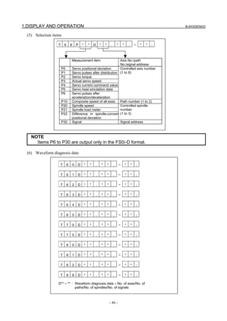
Guide to selecting items
- Alarm type
1 When the [(OPRT)] soft key is pressed with the cursor positioned at the alarm type in the trigger
setting, the [EXPLAN] soft key appears.
2 Pressing the [EXPLAN] soft key displays a list of alarm types.
- Data type
1 When the [(OPRT)] soft key is pressed with the cursor positioned at the trace data type in the trace
waveform setting, the [EXPLAN] soft key appears.
2 Pressing the [EXPLAN] soft key displays a list of trace data types.](https://image.slidesharecdn.com/fanuc0imaintenancemanual-140802043306-phpapp01/85/Fanuc-0i-maintenance-manual-CNC-milling-machine-60-320.jpg)
![B-64305EN/03 1.DISPLAY AND OPERATION
- 43 -
- Waveform color
1 When the [(OPRT)] soft key is pressed with the cursor positioned at the waveform color in the trace
waveform setting, the [EXPLAN] soft key appears.
2 Pressing the [EXPLAN] soft key displays a list of waveform colors
1.6.3 Tracing Data
Starting tracing
1 Display the waveform diagnosis graph screen.
2 Press the [TRACE] soft key to start tracing.
"Now Sampling…" appears in the upper part of the screen. When tracing ends, the indication "Now
Sampling…" disappears.
Even when the screen display is changed to another screen, tracing continues.
Canceling tracing
When the [CANCEL] soft key is pressed during tracing, tracing stops.
Moving, extending, and reducing a waveform](https://image.slidesharecdn.com/fanuc0imaintenancemanual-140802043306-phpapp01/85/Fanuc-0i-maintenance-manual-CNC-milling-machine-61-320.jpg)
![1.DISPLAY AND OPERATION B-64305EN/03
- 44 -
When [H-DOBL] or [H-HALF] soft key is pressed, the length of the time axis on one screen is extended
or reduced, respectively.
When a waveform cannot fit in one screen, the time axis can be moved by pressing [←TIME] or
[TIME→] soft key.
Furthermore, pressing [CH-1], [CH-2], [CH-3], or [CH-4] soft key, following submenu appears.
When [WAV.EX] or [WAV.RE] soft key is pressed, the length of the time axis on one screen is extended
or reduced, respectively. The graduation unit on the horizontal axis, which is a parameter, also changes
automatically.
The graduation unit changes from 1 to 2 to 5 to 10 to 20 to 50 to 100, and so on.
When [WAV.↑] or [WAV.↓] soft key is pressed, each waveform of servo and spindle data can be moved
upward or downward.
Displaying signal data
Up to 32 signals can be measured at the same time. Up to nine signals can be displayed at the same time
if only signal data is displayed, or up to four signals can be displayed if signal data is displayed over
waveforms.
When [SIG.↑] or [SIG.↓] soft key is pressed, the currently displayed signals are changed.
NOTE
Signal data cannot be moved.
1.6.4 Outputting Data
Waveform diagnosis data can be output to an input/output device.
Specifying a format
When outputting data, you can select one of the two formats, which are the FS0i-C compatible format and
the FS0i-D. If bit 0 (IOF) of parameter No. 10600 is set to 0, the FS0i-D format is selected; if bit 0
(IOF) of parameter No. 10600 is set to 1, the FS0i-C compatible format is selected.
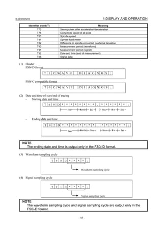
Output format
Traced data is output as a text file with the following format:
- Identifiers
Identifier word (T) Meaning
T0/T1 Header
T60 Servo positional deviation
T61 Servo pulses after distribution
T62 Servo torque
T63 Actual servo speed
T64 Servo current command value
T65 Servo heat simulation data
T68 Measurement item
T69 Date and time (start of measurement)](https://image.slidesharecdn.com/fanuc0imaintenancemanual-140802043306-phpapp01/85/Fanuc-0i-maintenance-manual-CNC-milling-machine-62-320.jpg)
![1.DISPLAY AND OPERATION B-64305EN/03
- 48 -
- Sample file (FS0i-D format)
Outputting a file
1 Display the waveform diagnosis graph screen.
2 When the [(OPRT)] soft key is pressed, soft keys are displayed in the following operation selection
state:
3 Change the mode to the EDIT mode.
T01WAVE DIAGNOSE
T69D20040101,120125
T92D20040101,120130
T90D2
T91D4
T68P0D1,2
T68P4D1
T68P10D1
T68P30DG0010.4,G0010.5,G0010.6
T60D643,6420
T64D270
T75D1855
T60D673,6451
T64D265
T75D1855
T60D702,6480
T64D268
T75D1855
:
T75D1855
T98D0,0,1
T98D0,0,1
T98D0,0,1
:
Header
Start time
End time
Waveform period
Signal period
Measurement item/axis
Measurement item/signal
Waveform data
Signal data](https://image.slidesharecdn.com/fanuc0imaintenancemanual-140802043306-phpapp01/85/Fanuc-0i-maintenance-manual-CNC-milling-machine-66-320.jpg)
![B-64305EN/03 1.DISPLAY AND OPERATION
- 49 -
4 Enter a file name in the key-in buffer, and press the [F OUTPUT] soft key. If no file name is input,
the file name is assumed to be WAVE-DGN.TXT by default.
5 Press the [EXEC] soft key shown below to start outputting data:
6 When data output ends, or when the [CAN] soft key is pressed, the initial operation selection state is
restored.
NOTE
While data is being traced, data output is not allowed.
Parameter
#7 #6 #5 #4 #3 #2 #1 #0
10600 IOF
[Input type] Parameter input
[Type of data] Bit
#0 IOF The output format used for waveform diagnosis is:
0: FS0i-D format.
1: FS0i-C compatible format.
1.7 COLOR SETTING SCREEN
The coloring screen can be used to specify screen coloring.
1.7.1 Screen Display
1 Press the function key .
2 Press the continuous menu key several times until the [COLOR] soft key is displayed.
3 Pressing the [COLOR] soft key displays the color setting screen.](https://image.slidesharecdn.com/fanuc0imaintenancemanual-140802043306-phpapp01/85/Fanuc-0i-maintenance-manual-CNC-milling-machine-67-320.jpg)
![1.DISPLAY AND OPERATION B-64305EN/03
- 50 -
1.7.2 Operations for Color Setting
Modification to color settings (color palette values)
1 Pressing the [(OPRT)] soft key displays the following operation soft keys:
2 Move the cursor to a color number whose color palette values are to be modified.
The current color palette values of the individual color elements are displayed.
3 Select a color element to be modified, with the [RED], [GREEN], or [BLUE] operation soft key.
Multiple color elements can be selected at a time.
Each of the [RED], [GREEN], and [BLUE] soft keys toggles between selection and deselection each
time the soft key is pressed.
(The [RED], [GREEN], and [BLUE] soft keys, when not displayed, can be displayed by pressing the
rightmost soft key.)
4 By pressing the [BRIGHT] or [DARK] operation soft key, modify the brightness of the selected
color element.
Storing color settings (color palette values)
Set color palette values can be stored.
1 Select a storage area by pressing the [COLOR1], [COLOR2], or [COLOR3] operation soft key.
(The [COLOR1], [COLOR2], and [COLOR3] soft keys, when not displayed, can be displayed by
pressing the rightmost soft key.)
Color 1: Standard color data parameters Nos. 6581 to 6595
Color 2: Parameters Nos. 10421 to 10435
Color 3: Parameters Nos. 10461 to 10475
2 Press the [MEMORY] operation soft key. The following operation soft keys are displayed:
3 Press the [EXEC] operation soft key. The current color palette values are stored in the selected area.
Pressing the [CAN] operation soft key or the leftmost key does not store the current color palette
values.
Calling color settings (color palette values)
1 Select an area for storing color palette values by pressing the [COLOR1], [COLOR2], or [COLOR3]
operation soft key.
(The [COLOR1], [COLOR2], and [COLOR3] soft keys, when not displayed, can be displayed by
pressing the rightmost soft key.)
2 Press the [RECALL] operation soft key. The following operation soft keys are displayed:
3 Press the [EXEC] operation soft key. Color palette values are called from the selected area for
modification to the color settings. This operation is invalid if no color palette values are stored.
Pressing the [CANCEL] operation soft key or the leftmost key does not call color palette values.](https://image.slidesharecdn.com/fanuc0imaintenancemanual-140802043306-phpapp01/85/Fanuc-0i-maintenance-manual-CNC-milling-machine-68-320.jpg)
![B-64305EN/03 1.DISPLAY AND OPERATION
- 51 -
1.7.3 Parameter
6581 RGB value of color palette 1
6582 RGB value of color palette 2
6583 RGB value of color palette 3
6584 RGB value of color palette 4
6585 RGB value of color palette 5
6586 RGB value of color palette 6
6587 RGB value of color palette 7
6588 RGB value of color palette 8
6589 RGB value of color palette 9
6590 RGB value of color palette 10
6591 RGB value of color palette 11
6592 RGB value of color palette 12
6593 RGB value of color palette 13
6594 RGB value of color palette 14
6595 RGB value of color palette 15
[Input type] Parameter input
[Data type] 2-word
[Valid data range] 0 to 151515
Each of these parameters sets the RGB value of each color palette by specifying a 6-digit
number as described below.
rrggbb: 6-digit number (rr: red data, gg: green data, bb: blue data)
The valid data range of each color is 0 to 15 (same as the tone levels on the color setting
screen). When a number equal to or greater than 16 is specified, the specification of 15 is
assumed.
Example)
When the tone level of a color is: red:1 green:2, blue:3, set 10203 in the parameter.
10421 RGB value of color palette 1 for color set 2
10422 RGB value of color palette 2 for color set 2
10423 RGB value of color palette 3 for color set 2
10424 RGB value of color palette 4 for color set 2
10425 RGB value of color palette 5 for color set 2](https://image.slidesharecdn.com/fanuc0imaintenancemanual-140802043306-phpapp01/85/Fanuc-0i-maintenance-manual-CNC-milling-machine-69-320.jpg)
![1.DISPLAY AND OPERATION B-64305EN/03
- 52 -
10426 RGB value of color palette 6 for color set 2
10427 RGB value of color palette 7 for color set 2
10428 RGB value of color palette 8 for color set 2
10429 RGB value of color palette 9 for color set 2
10430 RGB value of color palette 10 for color set 2
10431 RGB value of color palette 11 for color set 2
10432 RGB value of color palette 12 for color set 2
10433 RGB value of color palette 13 for color set 2
10434 RGB value of color palette 14 for color set 2
10435 RGB value of color palette 15 for color set 2
[Input type] Parameter input
[Data type] 2-word
[Valid data range] 0 to 151515
Each of these parameters sets the RGB value of each color palette by specifying a 6-digit
number as described below.
rrggbb: 6-digit number (rr: red data, gg: green data, bb: blue data)
The valid data range of each color is 0 to 15 (same as the tone levels on the color setting
screen). When a number equal to or greater than 16 is specified, the specification of 15 is
assumed.
Example)
When the tone level of a color is: red:1 green:2, blue:3, set 10203 in the parameter.
10461 RGB value of color palette 1 for color set 3
10462 RGB value of color palette 2 for color set 3
10463 RGB value of color palette 3 for color set 3
10464 RGB value of color palette 4 for color set 3
10465 RGB value of color palette 5 for color set 3
10466 RGB value of color palette 6 for color set 3
10467 RGB value of color palette 7 for color set 3
10468 RGB value of color palette 8 for color set 3
10469 RGB value of color palette 9 for color set 3
10470 RGB value of color palette 10 for color set 3
10471 RGB value of color palette 11 for color set 3](https://image.slidesharecdn.com/fanuc0imaintenancemanual-140802043306-phpapp01/85/Fanuc-0i-maintenance-manual-CNC-milling-machine-70-320.jpg)
![B-64305EN/03 1.DISPLAY AND OPERATION
- 53 -
10472 RGB value of color palette 12 for color set 3
10473 RGB value of color palette 13 for color set 3
10474 RGB value of color palette 14 for color set 3
10475 RGB value of color palette 15 for color set 3
[Input type] Parameter input
[Data type] 2-word
[Valid data range] 0 to 151515
Each of these parameters sets the RGB value of each color palette by specifying a 6-digit
number as described below.
rrggbb: 6-digit number (rr: red data, gg: green data, bb: blue data)
The valid data range of each color is 0 to 15 (same as the tone levels on the color setting
screen). When a number equal to or greater than 16 is specified, the specification of 15 is
assumed.
Example)
When the tone level of a color is: red:1 green:2, blue:3, set 10203 in the parameter.
1.7.4 Notes
(1) When the power is turned on, color 1 (parameter) is specified for the screen. If no data is stored in
color 1, the default color is used.
(2) Do not use MDI key inputs directly to change the color data parameter. To change it, do so by
performing storage operation on the coloring screen.
1.8 POWER MATE CNC MANAGER FUNCTION
When the I/O Link Option for the FANUC servo unit βi series (called I/O Link βi below) is used for CNC
additional axes (slaves), the Power Mate CNC manager function can be used to display and set up various
types of data of these slaves on the CNC.
The Power Mate CNC manager function enables the following display and setting operations:
(1) Current position display (absolute/machine coordinates)
(2) Parameter display and setting
(3) Alarm display
(4) Diagnosis data display
(5) System configuration screen display
Up to eight slaves can be connected to each I/O Link channel.
1.8.1 Screen Display
1 Press the function key .
2 Press the continuous menu key several times until the [P.MATE MGR.] soft key is displayed.
3 Pressing the [P.MATE MGR.] soft key displays the absolute coordinate screen, which is the initial
screen of the Power Mate CNC manager. On this screen, you can select each of the following
items by pressing the corresponding soft key:
[ABSOLUTE] : Absolute coordinate display (current position display screen)](https://image.slidesharecdn.com/fanuc0imaintenancemanual-140802043306-phpapp01/85/Fanuc-0i-maintenance-manual-CNC-milling-machine-71-320.jpg)
![1.DISPLAY AND OPERATION B-64305EN/03
- 54 -
[MACHINE] : Machine coordinate display (current position display screen)
[PARAMETER] : Parameter screen
[MESSAGE] : Alarm screen
[DIAGNOSIS] : Diagnosis screen
[SYSTEM CONFIG] : System configuration screen
To select another function after one of the functions listed above is selected, press the return menu
key until the soft keys appear as shown above. Then, select the desired function.
4 To terminate the Power Mate CNC manager function, first push the return menu key once or
twice. The CNC system soft key is displayed. Pressing this soft key lets you exit Power Mate
CNC manager.
Alternatively, pressing an MDI function key (such as , , or ) terminates the Power
Mate CNC manager function.
Selecting a slave
When slaves are connected to multiple I/O Link channels, pressing [NEXT CH.] or [PREV. CH.] soft key
displayed by pressing the [(OPRT)] soft key changes the displayed channel.
In the upper section of the screen, the following information items are displayed for the connected slaves
(up to eight slaves):
- I/O Link group number (0 to 15)
- Alarm status
The cursor is positioned at the number of the slave for which to display information (active slave).
When multiple slaves are connected, pressing the [NEXT SLAVE] or [PREV. SLAVE] soft key changes
the active slave.
You can display the slave status and select a slave on any screen of the Power Mate CNC manager
function.
Current position display screen
The current position display screen displays the current position and actual speed of the slave.
The following current position data is displayed:
Absolute coordinate (current position in the absolute coordinate system)
Machine coordinate (current position in the machine coordinate system)
- Display method
Press soft key [ABSOLUTE] to display the absolute coordinate screen.
Press soft key [MACHINE] to display the machine coordinate screen.](https://image.slidesharecdn.com/fanuc0imaintenancemanual-140802043306-phpapp01/85/Fanuc-0i-maintenance-manual-CNC-milling-machine-72-320.jpg)
![B-64305EN/03 1.DISPLAY AND OPERATION
- 55 -
Power Mate CNC manager: Machine coordinate screen
Axis name display
Parameter Nos. 0024 and 0025 on the I/O Link βi side are used to set axis names. Up to two characters
can be set. (Use the ASCII codes of 0 to 9 and/or A to Z). When no axis name is set or the setting data
is invalid, the axis name is set to 1.
This axis name is used only for position display of the Power Mate CNC manager function and irrelevant
to the controlled axis on the CNC.
Parameter screen
The parameters required for the functions of the slave must be specified in advance.
Press soft key [PARAMETER] to display the parameter screen.
This screen displays only the bit and decimal data. For details of the parameters, refer to FANUC
SERVO MOTOR βi series I/O Link Option Maintenance Manual.](https://image.slidesharecdn.com/fanuc0imaintenancemanual-140802043306-phpapp01/85/Fanuc-0i-maintenance-manual-CNC-milling-machine-73-320.jpg)
![1.DISPLAY AND OPERATION B-64305EN/03
- 56 -
• Selecting and searching for a parameter
1 Select the active slave.
2 Press the [(OPRT)] soft key. The following soft keys appear:
3 Enter a parameter number and press the [NO. SRH] soft key. The search starts.
You can also select a desired parameter number by pressing the cursor keys
and page keys and moving the cursor.
• Setting a parameter
You can directly set an parameter of the I/O Link βi slave from the CNC.
1 Select a desired parameter using either of the above methods.
2 Press the [(OPRT)] soft key. The following soft keys appear:
3 Enter setting data.
4 Press the [INPUT] soft key or MDI key .
Alarm screen
If an alarm is issued for the slave, “ALARM” is displayed in the slave status field in the upper section of
the screen.
At this time, you can display the alarm screen to check the details of the alarm.
Up to 40 alarm codes are displayed on the screen.
For details of the alarms, refer to FANUC SERVO MOTOR βi series I/O Link Option Maintenance
Manual.
- Display method
Press the [MESSAGE] soft key. On the screen, only error codes are displayed.
Example of displaying alarms for I/O Link βi of slave 2](https://image.slidesharecdn.com/fanuc0imaintenancemanual-140802043306-phpapp01/85/Fanuc-0i-maintenance-manual-CNC-milling-machine-74-320.jpg)
![B-64305EN/03 1.DISPLAY AND OPERATION
- 57 -
Diagnosis screen
The diagnosis screen displays diagnosis information of the slave.
Diagnosis data is displayed in bit or integer (decimal) representation. For details of diagnosis data, refer
to FANUC SERVO MOTOR βi series I/O Link Option Maintenance Manual.
- Display method
1 Press the continuous menu key .
2 Press soft key [DIAGNOSIS] to display the diagnosis screen.
Searching for diagnosis data
1 Select the active slave.
2 Press the [(OPRT)] soft key. The following soft keys appear:
3 Enter a diagnosis number and press the [NO. SRH] soft key. The search starts.
You can also select a desired parameter number by pressing the cursor keys and page
keys and moving the cursor.
System configuration screen
The system configuration screen displays information on the system software of slaves.
- Display method
1 Press the continuous menu key .
2 Press the [SYSTEM] soft key to select the system configuration screen.](https://image.slidesharecdn.com/fanuc0imaintenancemanual-140802043306-phpapp01/85/Fanuc-0i-maintenance-manual-CNC-milling-machine-75-320.jpg)
![1.DISPLAY AND OPERATION B-64305EN/03
- 58 -
Series and edition of the I/O Link βi system software
1.8.2 Inputting and Outputting Parameters
Outputting parameters
Parameters are output to the CNC memory or a memory card as a data file in the program format. Set
the first registration program number in parameter No. 8760. For each slave, program with a
predetermined number is created.
When parameters are output to the CNC memory, a program with the specified program number is
created.
When parameters are output to a memory card, a file is created, of which file name consists of the
specified program number and an extension PMM.
Program number = setting-of-parameter (parameter No. 8760) + (m - 1) × 100 + n × 10
m: Channel number (1 to 4)
n: Group number
Example:
When parameter No. 8760 is set to 8000
Channel 1 (I/O Link β: Group 0): 8000 + 0*100 + 0*10 = 8000
Channel 2 (I/O Link β: Group 1): 8000 + 1*100 + 1*10 = 8110
The group number is the slave number displayed in the slave status field in the upper section of the screen
in reverse video.
When bit 3 (PMO) of parameter No. 0961 is set to 1, the numbers of the parameters to be output can be
set only with a group number. (No channel number is used.)
Either the CNC memory or the memory card is selected as an input/output destination device according to
the settings of bits 1 (MD1) and 2 (MD2) of parameter No. 0960.
Connect a memory card or check the unused area of the CNC memory, then follow the steps below:
1 For 2-path control in T series systems, the Power Mate CNC manager screen is displayed directly
from a path 1 screen.
2 Select the active slave.
3 Press the [(OPRT)] soft key. The following soft keys appear:](https://image.slidesharecdn.com/fanuc0imaintenancemanual-140802043306-phpapp01/85/Fanuc-0i-maintenance-manual-CNC-milling-machine-76-320.jpg)
![B-64305EN/03 1.DISPLAY AND OPERATION
- 59 -
4 Press the [INPUT β→NC] soft key. The following soft keys appear:
5 Press the [EXEC] soft key.
During input, “INPUT” blinks in the message field.
NOTE
1 Parameters can be saved in other than the MEM mode or in the emergency stop
status.
2 To output parameters in a memory card, if a file with the same name is found in
the memory card, the parameters cannot be output. Delete the file from the
memory card or change the file name by setting parameter No. 8760.
To save parameters in a program area, save operation is performed according to
the setting of bit 2 (REP) of parameter No. 3201.
3 For 2-path control in T series systems, only the Power Mate CNC manager
screen of path 1 can be used to input and output parameters, and input/output is
enabled only for the CNC memory of path 1.
Inputting parameters
A data file of parameters output to the CNC memory or a memory card as a program is input to the slave
determined by the program number. The program number and device are determined as described in
“Outputting parameters.”
1 For 2-path control in T series systems, the Power Mate CNC manager screen is displayed directly
from a path 1 screen.
2 Select the active slave.
3 Press the [(OPRT)] soft key. The following soft keys appear:
4 Press the [OUTPUT β→NC] soft key. The following soft keys appear:
5 Press the [EXEC] soft key.
During output, “OUTPUT” blinks in the message field.
NOTE
1 Parameters can be input in other than the MEM mode or in the emergency stop
status.
2 For 2-path control in T series systems, only the Power Mate CNC manager
screen of path 1 can be used to input and output parameters, and input/output is
enabled only for the CNC memory of path 1.
1.8.3 Parameters
#7 #6 #5 #4 #3 #2 #1 #0
0960 PPE PMN MD2 MD1
[Input type] Setting input
[Data type] Bit path](https://image.slidesharecdn.com/fanuc0imaintenancemanual-140802043306-phpapp01/85/Fanuc-0i-maintenance-manual-CNC-milling-machine-77-320.jpg)
![1.DISPLAY AND OPERATION B-64305EN/03
- 60 -
#1 MD1
#2 MD2 The slave parameters are input from and output to either of the following devices:
Parameter MD2 Parameter MD1 I/O destination
0 0 Program memory
0 1 Memory card
#3 PMN The Power Mate CNC manager function is:
0: Enabled.
1: Disabled. (Communication with the slave is not performed.)
#4 PPE Setting slave parameters using the Power Mate CNC manager:
0: Can always be performed regardless of the setting of PWE.
1: Follows the setting of PWE.
#7 #6 #5 #4 #3 #2 #1 #0
0961 PMO
[Input type] Parameter input
[Data type] Bit
#3 PMO The O number of a program for saving and restoring the I/O Link β parameter is set based
on:
0: Group number and channel number
1: Group number only
8760 Program number of data input/output (Power Mate CNC manager)
[Input type] Setting input
[Data type] 2-word path
[Valid data range] 0 to 9999
This parameter sets the program numbers of programs to be used for inputting and
outputting slave data (parameters) when the Power Mate CNC manager function is used.
For a slave specified with I/O Link channel m and group n, the following program
number is used:
Setting + (m - 1) × 100 + n × 10
If the setting is 0, the parameters of the slave specified with channel 1 and group 0 cannot
be input from or output to the CNC memory because the program number is set to 0.
The parameters can be input from and output to a memory card.
(Set a value with which any used program number does not exceed 9999.)
Warning
If an alarm is issued for the Power Mate CNC manager, a warning message is displayed.
Message Description
DATA ERROR An attempt was made to execute [PUNCH] (NC → β) for a program not found in
the program area.
WRITE PROTECTED An attempt was made to execute [READ] (β → NC) for a program area when the
memory protection signal (KEY) is off.](https://image.slidesharecdn.com/fanuc0imaintenancemanual-140802043306-phpapp01/85/Fanuc-0i-maintenance-manual-CNC-milling-machine-78-320.jpg)
![B-64305EN/03 1.DISPLAY AND OPERATION
- 61 -
Message Description
EDIT REJECTED An attempt was made to execute [READ] (β → NC) when the program area
already contained a program with the same name as that to be created by
executing [READ] (β → NC).
An attempt was made to execute [READ] (β → NC) when the number of the
program to be created by executing [READ] (β → NC) was selected.
An attempt was made to execute [READ] (β → NC) when bit 0 (TVC) of CNC
parameter No. 0000 was set to 1. (Parameters Nos. 0000 to 0019 are output,
but parameter No. 0020 and subsequent parameters are not output.)
An attempt was made to execute [PUNCH] (NC → β) when a memory card did
not contain any program for which [PUNCH] (NC → β) could be executed.
An attempt was made to execute [READ] (β → NC) for a protected memory card.
NO MORE SPACE An attempt was made to execute [READ] (β → NC) when the program area did
not have enough unused space.
FORMAT ERROR Data other than digits, signs, CAN, and INPUT was entered as the setting of a
parameter.
TOO MANY FIGURES Data consisting of 9 or more digits was entered for a bit-type parameter.
DATA IS OUT OF RANGE The setting exceeds the valid data range.
1.8.4 Notes
- Connecting an I/O Link
When I/O Link βi is used as a slave of an I/O Link, the CNC assigns I/O addresses. The slave data is
input and output in 16-byte units. Therefore, be sure to specify 128 as the number of input/output
points.
Up to eight slaves can be connected.
The module name is OC02I (16-bit input) or OC02O (16-byte output).
BASE is always 0 and SLOT is always 1.
- Function of ignoring the Power Mate CNC manager
After setting and checking data required for each slave connected, you can stop communication with the
Power Mate CNC manager function to send a command from the CNC ladder to the slave.
When bit 3 (PMN) of parameter No. 0960 is set to 1, communication between the CNC and the slave via
the I/O Link is all open to the ladder. While this bit is 1, the Power Mate CNC manager function does
not operate.
- Data protection key
When the program data protection key of the CNC is on, no parameters can be input to the CNC program
memory.
1.9 MAINTENANCE INFORMATION SCREEN
The maintenance information screen is provided to record the history of maintenance performed by a
service person of FANUC or machine tool builder.
The screen has the following features:
• MDI alphabetical input is allowed.
(Only in Japanese display, even the single-byte kana input mode is allowed.)
• The recording screen can be scrolled in units of lines.
• Edited maintenance information can be input and output.
• Records are stored in Flash ROM.
• Double-byte (Shift JIS) code can be displayed.](https://image.slidesharecdn.com/fanuc0imaintenancemanual-140802043306-phpapp01/85/Fanuc-0i-maintenance-manual-CNC-milling-machine-79-320.jpg)
![1.DISPLAY AND OPERATION B-64305EN/03
- 62 -
1.9.1 Displaying the Maintenance Information Screen
1. Press function key .
2. Press continuous menu key several times until soft key [M-INFO] is displayed.
3. Press the soft key [M-INFO]. The maintenance information screen appears.
When selected, the maintenance information screen shows the latest information.
The status (mode, number of empty character spaces, current cursor line, current column number) is
displayed at the bottom of the screen.
Fig. 1.9.1 (a) MAINTENANCE INFORMATION screen
Status display
<1> Kana/alphabetic
(Blank): English input mode (Only In the display which is not Japanese)
: Single-byte kana input mode (Only in Japanese display)
: English input mode (Only in Japanese display)
<2> OVER / INSERT
: Overwrite mode
: Insert input mode.
<3> EDIT / READ
: Edit mode / Editing allowed
: View mode / Editing inhibited
<4> Number of empty character spaces
Number of empty character spaces as single-byte characters
<5> Current cursor line
Current cursor position on the line
<6> Current cursor column
Current cursor position on the column
NOTE
The numbers of lines and columns that can be displayed by each LCD are:
• 10.4” display unit: 37 characters × 12 lines
• 8.4” display unit: 38 characters × 11 lines
Column
Line
<1> <2> <3> <4> <5> <6>](https://image.slidesharecdn.com/fanuc0imaintenancemanual-140802043306-phpapp01/85/Fanuc-0i-maintenance-manual-CNC-milling-machine-80-320.jpg)
![B-64305EN/03 1.DISPLAY AND OPERATION
- 63 -
1.9.2 Operating the Maintenance Information Screen
The maintenance information screen has view mode and edit mode, which are selected by pressing the
soft key [END] or [EDIT].
Initially, view mode is selected. To start editing, select edit mode by pressing the soft keys [(OPRT)] and
[EDIT]. When the editing is completed, press the soft key [END] key. Then, select soft key [SAVE] or
[QUIT]. If [SAVE] is selected, edited data is saved to FLASH-ROM. If [QUIT] is selected, no edited
data is saved to FLASH-ROM.
To scroll the screen showing the recorded information, press a cursor keys or page keys on the MDI
panel.
The following keys are used for editing (character input) and viewing:
Table 1.9.2 (a) Table of (edit) operations on the maintenance information screen
Mode Key Description
Soft key
[EDIT] Allows editing.
[JUMP] Displays the beginning or the end.
Cursor keys Scrolls the screen up or down.
View
Page keys Scrolls the screen up or down in units of whole screens.
Soft key
[END] Ends editing. Select whether to save the edited data.
[ ]
Switches between single-byte kana input and alphabetic input modes.
(Japanese display only.)
[CLEAR] Clears all maintenance information. (This key is enabled when the
parameter MDC (No.3116#7) is set to 1.)
[I/O] Performs [F INPUT] or [F OUTPUT] operation for maintenance information.
[JUMP] Moves the cursor to the beginning or end.
Cursor keys Moves the cursor position up or down.
Page keys Scrolls the screen up or down in units of whole screens.
Address / numeric
keys
Allows alphabetical or numeric input. (See the next subsection for
explanations about single-byte kana input.)
key Switches between insert and overwrite modes.
key
• If the key input buffer does not contain any character, deletes the one
character at the cursor position.
• If the key input buffer contains characters, deletes the characters from the
buffer.
key
• If the key input buffer does not contain any character, deletes the one
character before the cursor.
• If the key input buffer contains characters, deletes the one character from
the buffer.
Edit
key
• If the key input buffer does not contain any character, starts a new line.
• If the key input buffer contains characters, outputs the characters from the
buffer to the information screen.
1.9.3 Single-Byte Kana Input on the Maintenance Information
Screen
By pressing soft key [ ], you can switch between single-byte kana input and alphabetic input
modes.
In single-byte kana input mode, alphabetic characters are converted in accordance with the "single-byte
kana/Roman character conversion table" and resultant single-byte kana characters are displayed in the key
input buffer. (Japanese display only.)](https://image.slidesharecdn.com/fanuc0imaintenancemanual-140802043306-phpapp01/85/Fanuc-0i-maintenance-manual-CNC-milling-machine-81-320.jpg)
![1.DISPLAY AND OPERATION B-64305EN/03
- 64 -
Pressing the key causes the characters in the key input buffer to be output to maintenance
information.
Pressing the key causes the characters to be deleted from the key input buffer and the one
character of the maintenance information on which the cursor is positioned to be deleted.
Pressing the key causes cancels conversion, and deletes one character from the key input buffer. If
the key input buffer does not contain any character, the one character of the maintenance information that
immediately precedes the cursor is deleted.
1.9.4 Warnings that Occurs on the Maintenance Information
Screen
The following warnings occur on the maintenance information screen.
Warning message Meaning
NO MORE SPACE An overflow occurred in CNC memory.
ALARM The operation could not be performed because an alarm was generated in the CNC.
BUSY Wait for CNC processing to end or make a retry.
ILLEGAL DATA Investigate data and correct it as required.
WRONG MODE The CNC is in wrong mode.
COMMAND ILLEGAL USE A corresponding CNC option cannot be found.
PARAMETER ERROR CNC parameter settings contain an error.
EDIT REJECTED An attempt was made to perform an edit operation on data that could not be edited.
WRITE PROTECT Writing is prohibited.
COMMAND REJECT The CNC rejected the execution of the processing. Check the execution conditions.
1.9.5 Parameter
#7 #6 #5 #4 #3 #2 #1 #0
3116 MDC
[Input type] Setting input
[Data type] Bit path
#7 MDC Maintenance information data:
0: Cannot be erased entirely.
1: Can be erased entirely.
#7 #6 #5 #4 #3 #2 #1 #0
3206 MIF
[Input type] Parameter input
[Data type] Bit
#1 MIF Editing of the maintenance information screen is:
0: Not prohibited.
1: Prohibited.](https://image.slidesharecdn.com/fanuc0imaintenancemanual-140802043306-phpapp01/85/Fanuc-0i-maintenance-manual-CNC-milling-machine-82-320.jpg)
![B-64305EN/03 1.DISPLAY AND OPERATION
- 65 -
#7 #6 #5 #4 #3 #2 #1 #0
8901 MEN
[Input type] Setting input
[Data type] Bit path
#7 MEN The periodic maintenance screen is:
0: Displayed.
1: Not displayed.
1.10 CONTENTS-OF-MEMORY DISPLAY SCREEN
The contents-of-memory display screen can be used to display the contents of the CNC memory, starting
at a specified address.
1.10.1 Display Method
1 Set bit 0 (MEM) of parameter No. 8950 to 1 to display the contents-of-memory display screen.
2 Press the function key .
3 Press the continuous menu key and then the soft key [MEMORY] belonging to the chapter
selection soft key.
The screen shown below appears.
Fig. 1.10.1 (a) Contents-of-memory display screen (10.4-inch)
4 Key in the address (hexadecimal) of a desired location and press the soft key [ADDRES SEARCH].
256 bytes of data are displayed, starting at the specified address.
(Example: 100000 + soft key [ADDRES SEARCH] will start displaying at 100000H.)
5 Displayed data can be switched using the page keys and the cursor keys
.
6 To select the type of data to be displayed, use the soft keys [BYTE], [WORD], [LONG], and
[DOUBLE].](https://image.slidesharecdn.com/fanuc0imaintenancemanual-140802043306-phpapp01/85/Fanuc-0i-maintenance-manual-CNC-milling-machine-83-320.jpg)
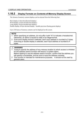
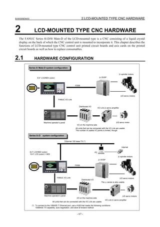
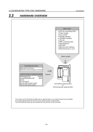
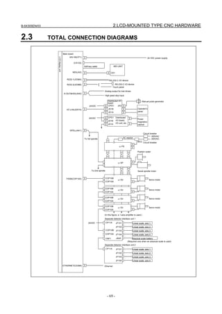
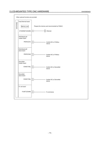
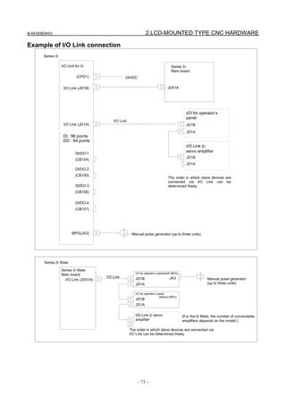
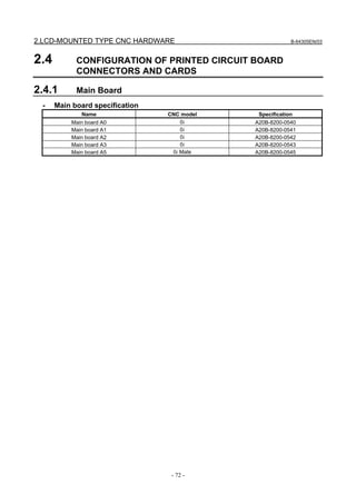
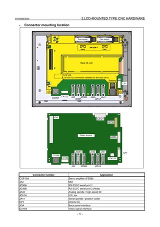
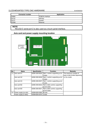
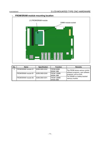
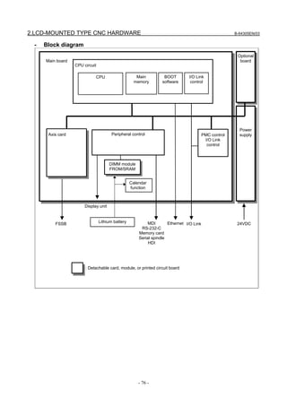
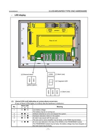
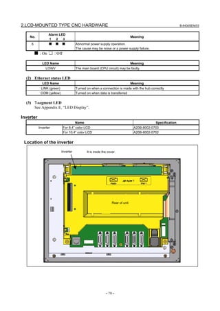
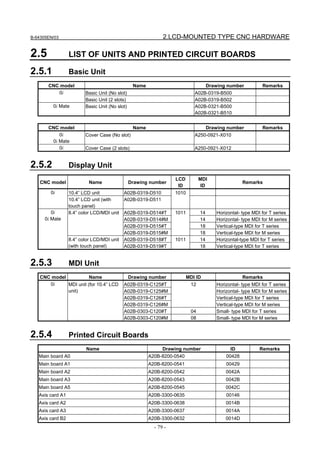
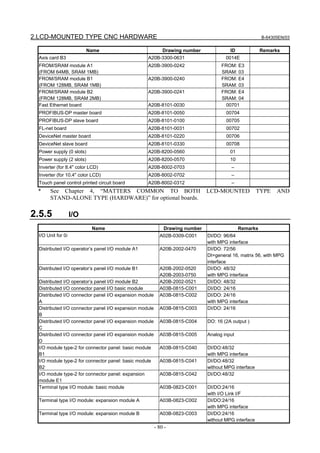
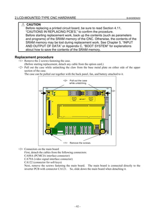
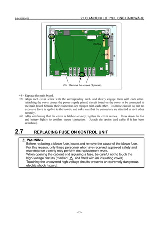
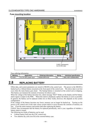
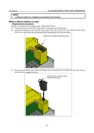
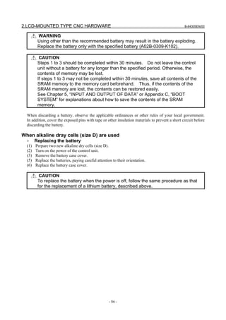
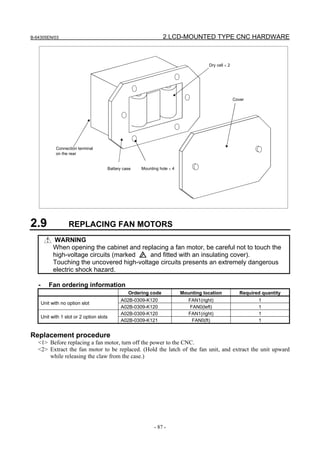
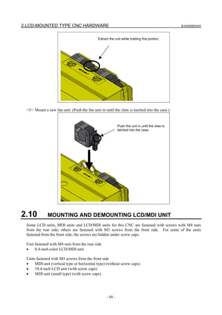
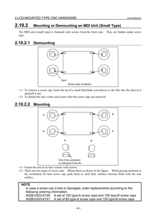

![2.LCD-MOUNTED TYPE CNC HARDWARE B-64305EN/03
- 92 -
<5> Press the adhesive parts of the four sides, and attach the entire sheet completely.
Check that the four corners and four sides of the protection sheet do not float.
(3) Checks after replacement
<1> Check that there is no wrinkle on the surface of the protection sheet.
<2> After power-on, check that there is no touch panel portion kept pressed.
<3> Press the touch panel, and check that correct operation takes place.
Touch panel calibration
- Conditions that require calibration
Touch panel calibration is needed under the following conditions:
(1) The LCD unit was replaced.
(2) The touch panel was replaced.
(3) The touch panel control printed-circuit board was replaced.
(4) Memory all clear was performed.
- Parameter
#7 #6 #5 #4 #3 #2 #1 #0
3113 DCL
[Input type] Parameter input
[Data type] Bit
# 5 DCL The touch panel compensation screen is:
0: Disabled.
1: Enabled.
Set this parameter to 0 usually. Touch panel compensation becomes necessary only when
the panel is replaced or memory all clear operation is performed. Set this parameter to 1
only when performing touch panel compensation. Upon completion of compensation, set
this parameter to 0.
- Calibration method
Calibration procedure
<1> Enable the touch panel calibration screen.(Set bit 5 (DCL) of parameter No. 3113 to 1.)
<2> Press function key .
<3> Press the continuous menu key several times. The [TOUCH PANEL] soft key is displayed.](https://image.slidesharecdn.com/fanuc0imaintenancemanual-140802043306-phpapp01/85/Fanuc-0i-maintenance-manual-CNC-milling-machine-110-320.jpg)
![B-64305EN/03 2.LCD-MOUNTED TYPE CNC HARDWARE
- 93 -
<4> Press the [TOUCH PANEL] soft key then the [(OPRT)] soft key. The [TP CAL] soft key is
displayed.
<5> Pressing the [TP CAL] soft key causes a full-screen touch panel calibration screen to appear.
<6> Click the 9 calibration points with a stylus pen. The marker of a normally clicked point changes
from "+" to "o". If you fail to click right on a "+" mark, the message "Your stylus pen is not right
on a "+" mark. Click again." appears.
<7> After clicking all 9 calibration points, clicking the key completes calibration. To quit or
retry calibration, click the key. The previous screen appears again. Before clicking 9
calibration points, clicking the key aborts calibration.
<8> When calibration ends normally, the message "Calibration ended" appears.
<9> After completing calibration, disable the touch panel calibration screen (by resetting the bit 5 (DCL)
of parameter No. 3113 to 0) to prevent operation mistake.](https://image.slidesharecdn.com/fanuc0imaintenancemanual-140802043306-phpapp01/85/Fanuc-0i-maintenance-manual-CNC-milling-machine-111-320.jpg)
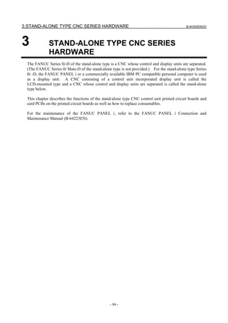
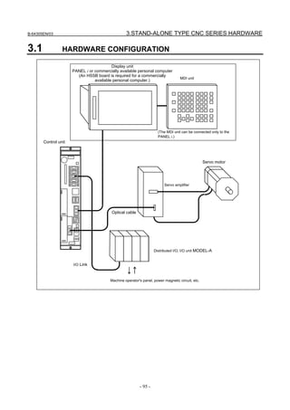
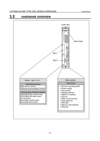
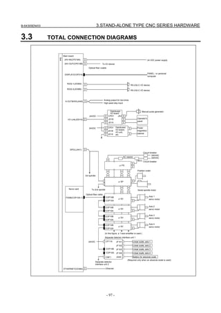
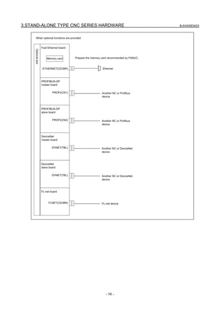

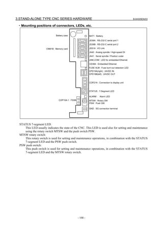
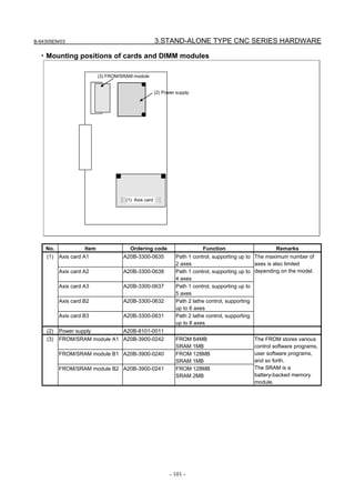
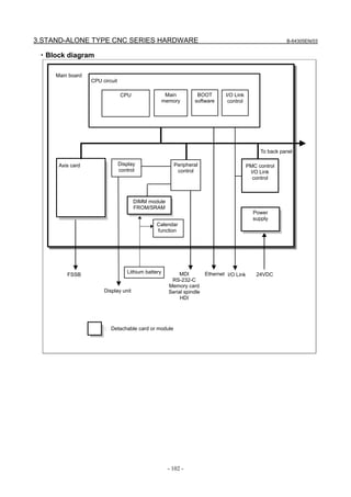
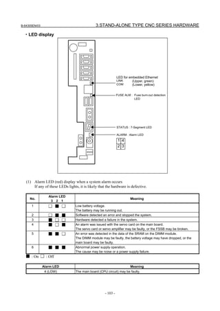
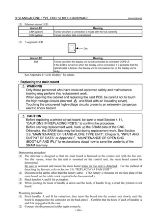
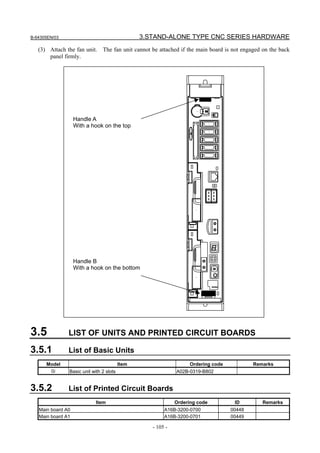
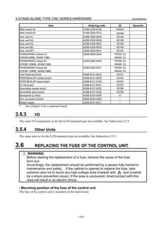
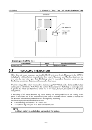
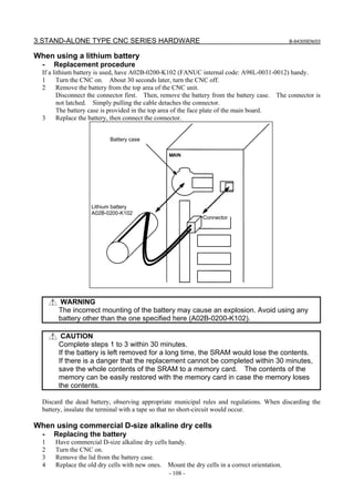
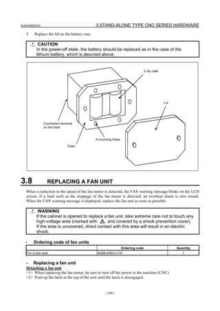

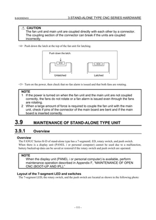
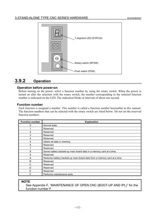
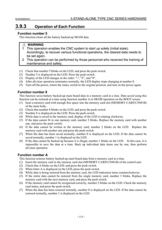
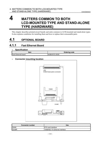
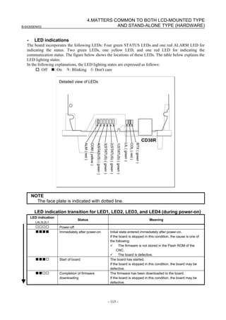
![B-64305EN/03
- 116 -
4. MATTERS COMMON TO BOTH LCD-MOUNTED TYPE
AND STAND-ALONE TYPE (HARDWARE)
LED indication
L4L3L2L1
Status Meaning
■□□□ Firmware OS started. The firmware OS has started.
If the board is stopped in this condition, the cause is one of
the following:
The firmware stored in the Flash ROM of the CNC is
destroyed.
The board is defective.
□■■■ Completion of firmware OS
initialization
Initialization of the firmware OS is completed.
If the board is stopped in this condition, the cause is one of
the following:
The firmware stored in the Flash ROM of the CNC is
destroyed.
The board is defective.
□■■☆ Completion of parameter
reading
The Ethernet parameters have been read.
If the board is stopped in this condition, the cause is one of
the following:
The Ethernet option or Data Server option is not
installed.
The IP address or subnet mask is not set.
□□□☆ Start completion The board has started normally.
LED indication for LED1, LED2, LED3, and LED4 (during normal operation)
LED indication
L4L3L2L1
Status Meaning
□□□☆ Normal status The board is operating normally.
LED indication for BTX, LIL, COM, and ALM (during normal operation)
LED indication Status Meaning
BTX ■ 100BASE-TX connection in
progress
The communication rate is 100BASE-TX.
BTX □ 10BASE-T connection in
progress
The communication rate is 10BASE-T.
LIL ■ Connected to hub The board is connected to the hub.
COM ■ Transmission/reception in
progress
Data is being transmitted or received.
ALM □ No alarm No alarm is issued
LED indication for LED1, LED2, LED3, and LED4 (when abnormality occurs)
The STATUS LEDs are turned on and off repeatedly with long on-time and short on-time.
LED
indication
[Long
on-time]
4 3 2 1
LED
indication
[Short
on-time]
4 3 2 1
Status Description
■■□□ □□□■ Error on another board A defect on another board or a problem on another
board was detected.
■■□□ □□■□ Bus error Software has a problem, or the board is defective.
■■□□ □□■■ Parity alarm The board is defective.
■□■□ □□□□ Illegal general instruction Software has a problem, or the board is defective.
■□■□ □□□■ Illegal slot instruction Software has a problem, or the board is defective.
■□■□ □■□□ CPU address error Software has a problem, or the board is defective.](https://image.slidesharecdn.com/fanuc0imaintenancemanual-140802043306-phpapp01/85/Fanuc-0i-maintenance-manual-CNC-milling-machine-134-320.jpg)
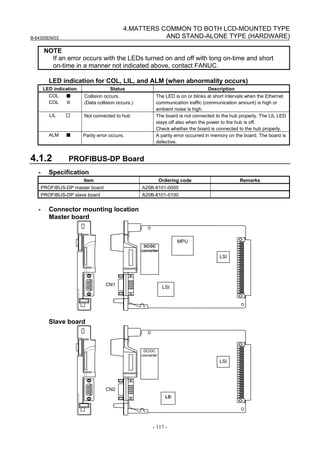
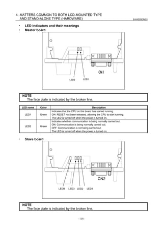
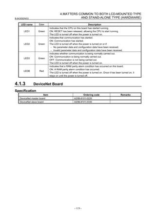
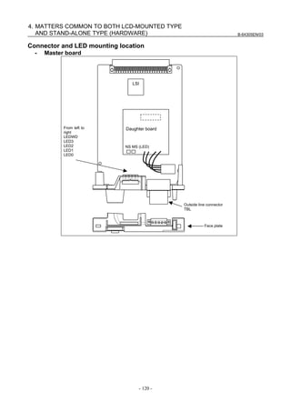
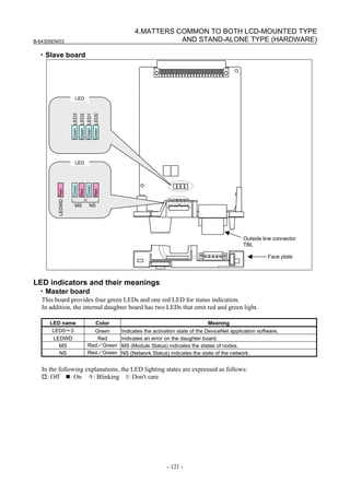
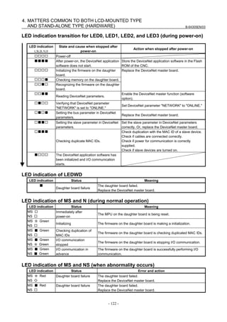
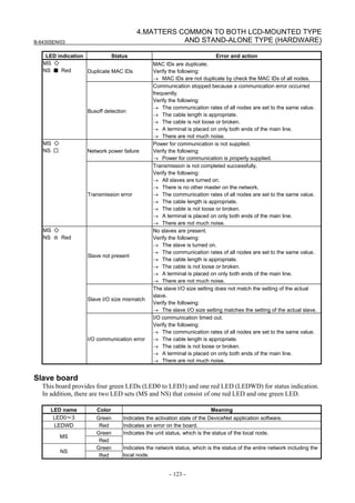
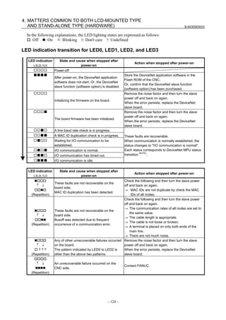
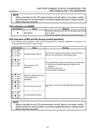
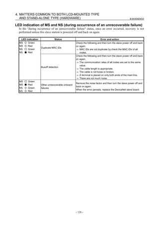
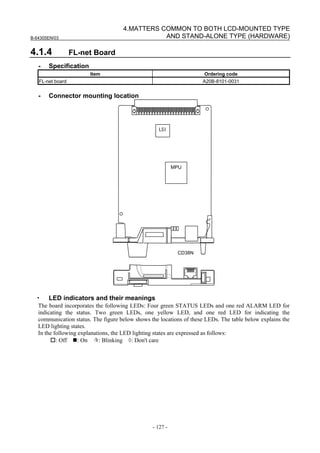
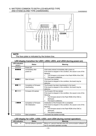
![B-64305EN/03
- 129 -
4.MATTERS COMMON TO BOTH LCD-MOUNTED TYPE
AND STAND-ALONE TYPE (HARDWARE)
LED indication Status Meaning
RES □ Normally OFF Normally, off
LNK ■ Participating in network Turned on when the node participates in the FL-net network
POK ■ Normal parameters Turned on when all FL-net parameters are valid.
LED display for BTX, LIL, COM, and ALM (during normal operation)
LED indication Status Meaning
BTX □ 10BASE-T connection in progress The communication rate is 10BASE-T.
BTX ■ 100BASE-TX connection in progress The communication rate is 100BASE-TX.
LIL ■ Connected to hub The board is connected to the hub.
COM ■ Transmission/reception in progress Data is being transmitted or received.
ALM □
(HER)
No alarm No alarm is issued
LED display for LED1, LED2, LED3, and LED4 (when abnormality occurs)
The STATUS LEDs are turned on and off repeatedly with long on-time and short on-time.
LED indication
[Long on-time]
4 3 2 1
LED indication
[Short on-time]
4 3 2 1
Status Description
■■□□ □□□■ Error on another
board
A defect on another board or a problem on another
board was detected.
■■□□ □□■□ Bus error Software has a problem, or the board is defective.
■■□□ □□■■ Parity alarm The board is defective.
■□■□ □□□□ Illegal general
instruction
Software has a problem, or the board is defective.
■□■□ □□□■ Illegal slot instruction Software has a problem, or the board is defective.
■□■□ □■□□ CPU address error Software has a problem, or the board is defective.
NOTE
If an error occurs with the LEDs turned on and off with long on-time and short
on-time in a manner not indicated above, contact FANUC.
LED display for COL, LIL, and ALM (when abnormality occurs)
LED indication Status Description
COL ■
COL ☆
Collision occurs.
(Data collision occurs.)
When a data collision occurs on the network, the LED is lit or blinks.
(Note)
LIL □ Not connected to hub The board is not connected to the hub properly. The LIL LED stays
off also when the power to the hub is off.
Check whether the board is connected to the hub properly.
ALM ■
(HER)
Parity error occurs. A parity error occurred in memory on the board. The board is
defective.
NOTE
The FL-net manages the token-based transmission right so that no collision
occurs. If this LED is turned on frequently, a communication error has occurred
due to noise, or an Ethernet compliant product other than the FL-net is
connected.
In such a case, check the devices connected to the network and the network
installation status.](https://image.slidesharecdn.com/fanuc0imaintenancemanual-140802043306-phpapp01/85/Fanuc-0i-maintenance-manual-CNC-milling-machine-147-320.jpg)
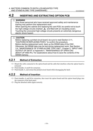
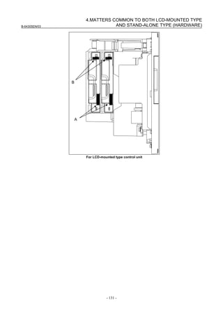
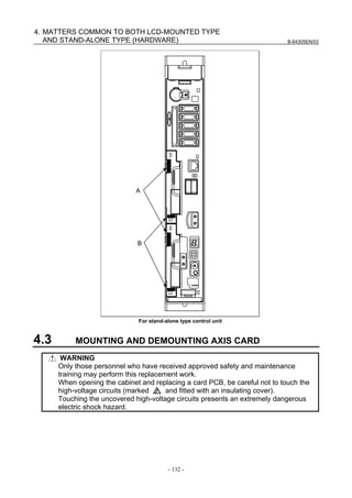
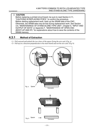
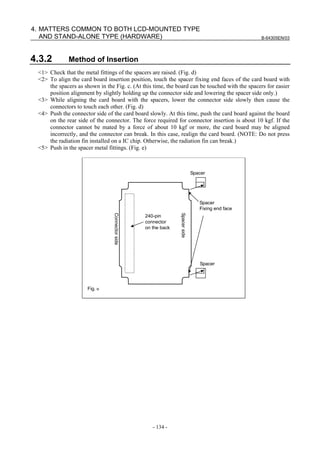
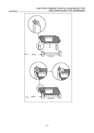
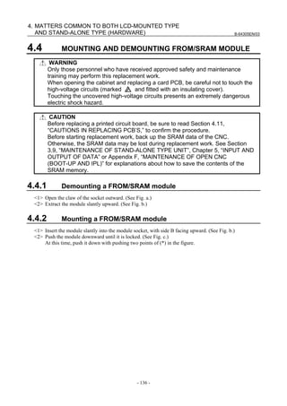
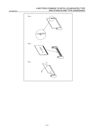
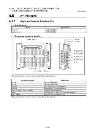
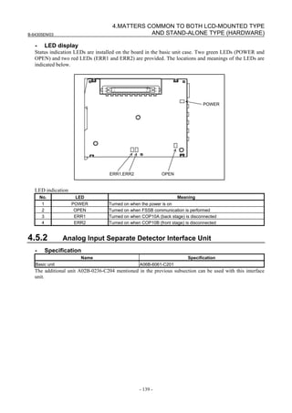
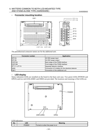
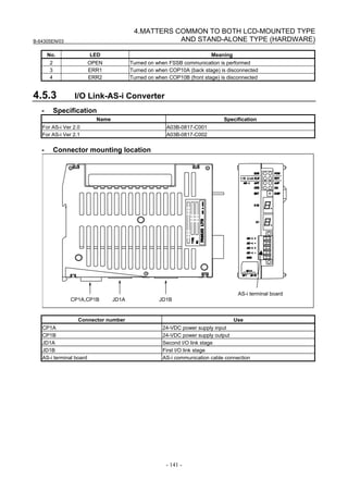
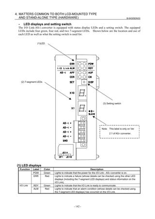
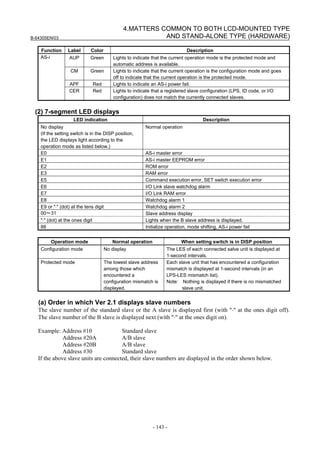
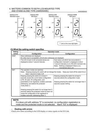
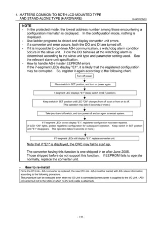
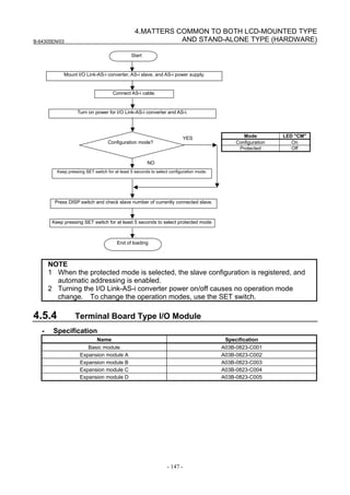
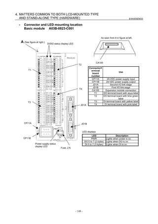
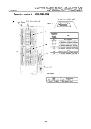
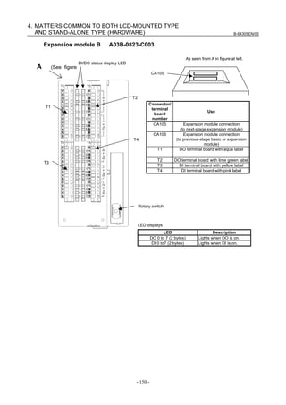
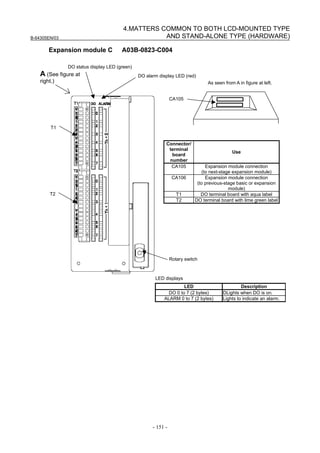
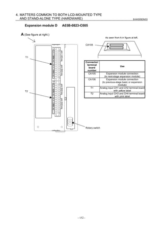
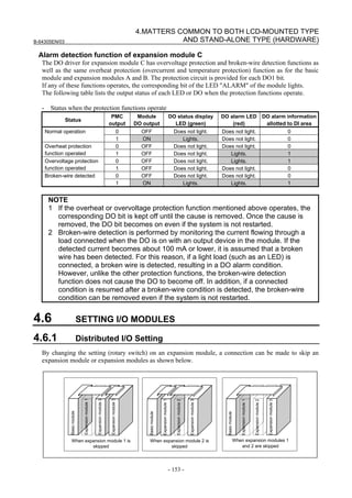
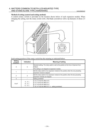
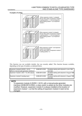
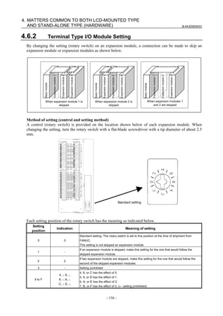
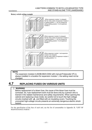
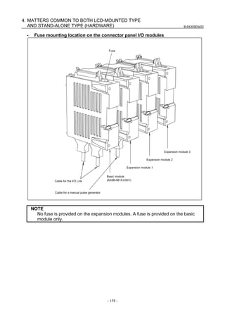
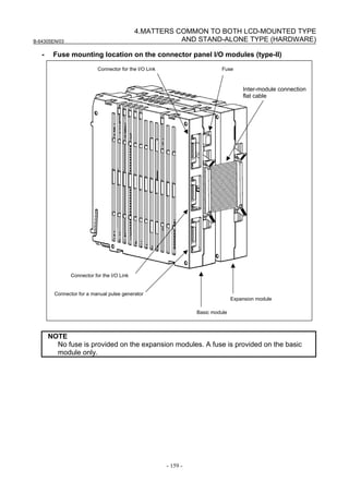
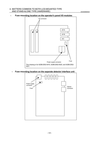
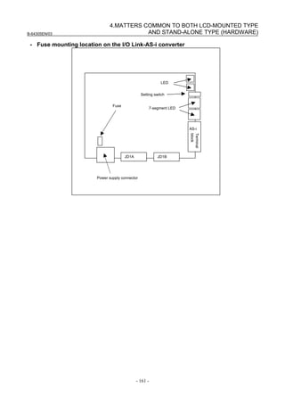
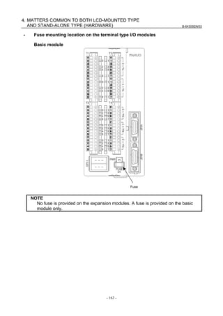
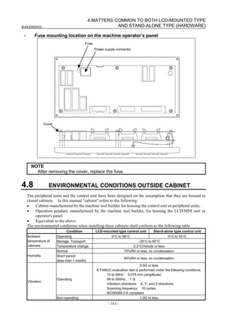
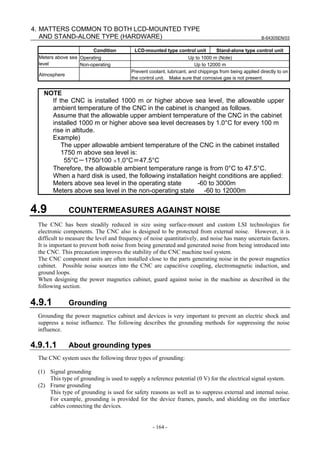
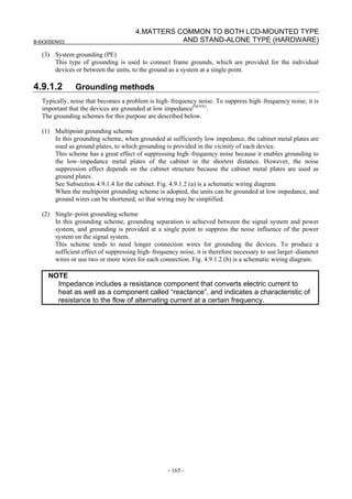
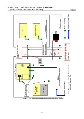
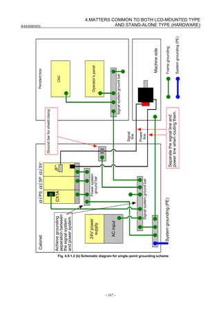

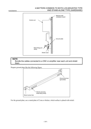
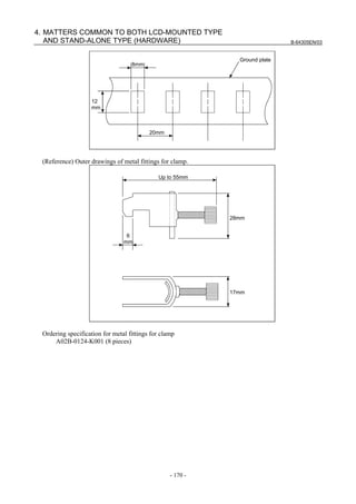
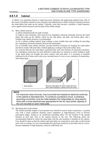
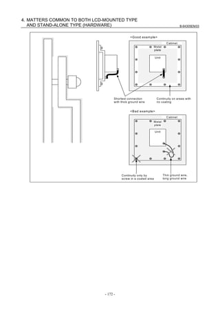
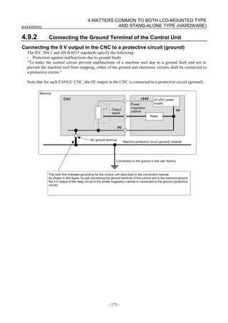
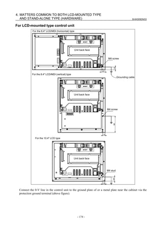
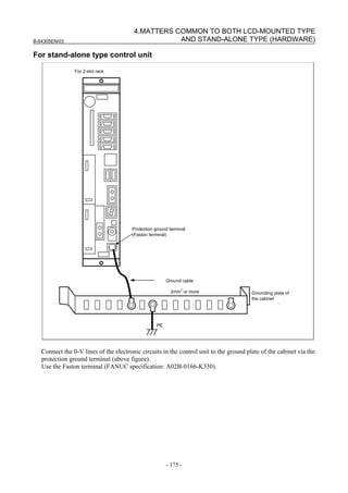
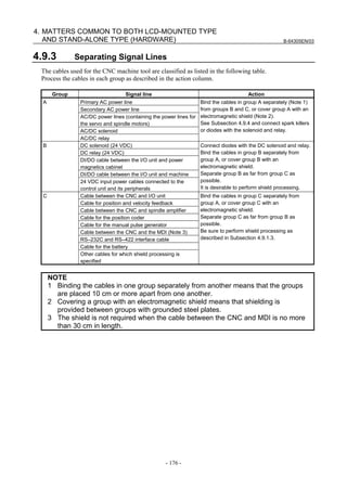
![B-64305EN/03
- 177 -
4.MATTERS COMMON TO BOTH LCD-MOUNTED TYPE
AND STAND-ALONE TYPE (HARDWARE)
4.9.4 Noise Suppressor
The AC/DC solenoid, AC/DC relay, and other devices are used in the power magnetics cabinet.
A high pulse voltage is caused by coil inductance when these devices are turned on or off.
This pulse voltage is induced through a cable or any other component, causing the electronic circuits to be
disturbed.
Take the following measures against the pulse voltage:
1) See Subsection 4.9.3 for groups A and B, and use spark killers for AC circuits or diodes for DC
circuits.
2) See “Notes on selecting the spark killer” below for information about selection of spark killers or
diodes.
Notes on selecting the spark killer
• Use a CR–type spark killer. (Use it for AC circuits.)
(A varistor is useful in clamping the peak pulse voltage, but cannot suppress the sudden rise of the
pulse voltage. FANUC therefore recommends the use of a CR–type spark killer.)
• The reference CR values of the spark killer shall conform to the following based on the current ((I
(A)) and DC resistance of the coil in the stationary state:
1) Resistance (R) : Equivalent of the DC resistance of the coil
2) Capacitance (C) :
20
~
10
22
II
(μF)
I :Current of the coil in the stationary state [A]](https://image.slidesharecdn.com/fanuc0imaintenancemanual-140802043306-phpapp01/85/Fanuc-0i-maintenance-manual-CNC-milling-machine-195-320.jpg)
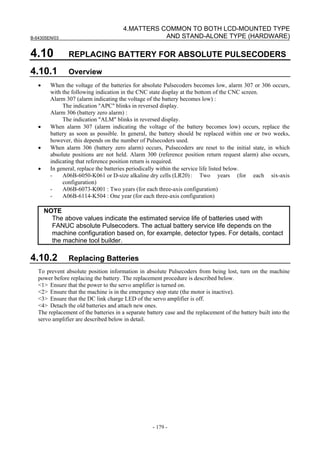
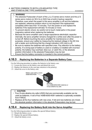
![B-64305EN/03
- 181 -
4.MATTERS COMMON TO BOTH LCD-MOUNTED TYPE
AND STAND-ALONE TYPE (HARDWARE)
CAUTION
・ Purchase the battery from FANUC because it is not commercially available. It is
therefore recommended that you have a backup battery.
・ When the built-in battery is used, do not connect BATL (B3) of connector
CXA2A/CXA2B. Also, do not connect two or more batteries to the same BATL
(B3) line. These connections are dangerous because battery output voltages
may be short-circuited, causing the batteries to overheat.
・ Install the battery in the servo amplifier in a direction that allows slack in the
cable. If the battery cable is under tension, a bad connection may occur.
・ If the +6 V pin and 0 V pin are short-circuited, the battery may overheat, blow
out, or catch fire, or the absolute position information in the absolute
Pulsecoders may be lost.
・ When inserting the connector, align it to the connector pins.
[Connecting the battery]
The battery for the βiSV4 and βiSV20 series amplifiers is mounted in the battery case on the underside of
each of the amplifiers.
The battery for the other βi series amplifiers and the αi series amplifiers is mounted at the front of each of
the amplifiers.
[αi series][βi series βi SV40, βi SV80, βi SVSP] [βi series βi SV4, βi SV20]
Battery
Battery case
Insertion direction
Red: +6 V
Black: 0 VConnector
Cable side Insertion direction
Cable side
Red: +6 V
Black: 0 V
CX5X
+6 V
0 V
Connector
Battery
Battery case
CX5X
+6 V
0 V
[Battery sets and outlines]
Battery ordering
drawing number
Manufacturer
model number
Applicable servo amplifier
Battery case
ordering drawing
number
Outline
αi series 60/90 mm width A06B-6114-K505
αi series 150/300 mm width A06B-6114-K506
βi series βi SV
(two-axis model)
A06B-6114-K505
A06B-6114-K504
(Note)
BR-2/3AGCT4A
(Panasonic)
βi series βi SVSP A06B-6114-K506
βi series βiSV4, βiSV20 A06B-6093-K002
A06B-6093-K001
BR-AGCF2W
(Panasonic) βi series βiSV40, βiSV80 A06B-6093-K002
NOTE
When an old type BR-CCF2TH battery is used, order a battery case that
accommodates battery A06B-6114-K504.
Used batteries
Old batteries should be disposed as "INDUSTRIAL WASTES" according to the regulations of the
country or autonomy where your machine has been installed.](https://image.slidesharecdn.com/fanuc0imaintenancemanual-140802043306-phpapp01/85/Fanuc-0i-maintenance-manual-CNC-milling-machine-199-320.jpg)
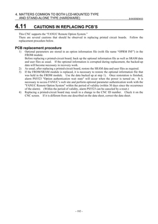
![B-64305EN/03 5.INPUT AND OUTPUT OF DATA
- 183 -
5 INPUT AND OUTPUT OF DATA
Parameters, offset values, and other data can be backed up in external I/O devices. SRAM data can also
be backed up at a time. This backup data can be restored to set data again easily. It is recommended
that various types of data and SRAM data be backed up periodically in case data stored in the CNC is
destroyed due to an operation error or backup battery exhaustion.
This chapter explains how to input or output data, such as parameters, part programs, and tool offset
values, with external I/O devices such as floppy disk units.
This chapter also explains automatic data backup (optional function) that automatically backs up SRAM
data periodically.
5.1 SETTING PARAMETERS FOR INPUT/OUTPUT ........................................................................183
5.2 INPUTTING/OUTPUTTING DATA...............................................................................................185
5.3 AUTOMATIC DATA BACKUP......................................................................................................189
SRAM data can be saved and restored at a time using the boot system. For details of the boot system,
see Appendix C, “BOOT SYSTEM,” and Appendix F, “MAINTENANCE OF OPEN CNC (BOOT-UP
AND IPL).”
For details of Inputting and Outputting Parameters of the I/O Link Option for the FANUC servo unit βi
series (I/O Link βi), see section 1.8.2. For details of PMC data Input/Output, see section 6.4.7.
5.1 SETTING PARAMETERS FOR INPUT/OUTPUT
Setting procedure of parameters
Parameter writing is enabled with following steps 1 to 3.
1 Set to MDI mode or emergency stop state.
2 Press function key several times or press soft key [SETTING] to display SETTING
(HANDY) screen.
3 Set the cursor to PARAMETER WRITE and, press and keys in this order. Here alarm
100 will be displayed.
4 Press function key several times to display the following screen.
0 0 0 0 0 0 0 0
0001 FCV
0 0 0 0 0 0 0 0
0012 RMV MIR
X 0 0 0 0 0 0 0 0
Y 0 0 0 0 0 0 0 0
Z 0 0 0 0 0 0 0 0
B 0 0 0 0 0 0 0 0
0020 I/O CHANNEL
S 0 T0000
PARAMETER (SETTING) O1234 N12345
0000 SEQ INI ISO TVC
To make the cursor
display in bit unit,
press the cursor key
or .REF **** *** *** 10: 15: 30
[ PARAM][ DGNOS][ ][SYSTEM][(OPRT)]](https://image.slidesharecdn.com/fanuc0imaintenancemanual-140802043306-phpapp01/85/Fanuc-0i-maintenance-manual-CNC-milling-machine-201-320.jpg)
![5.INPUT AND OUTPUT OF DATA B-64305EN/03
- 184 -
5 Press soft key [(OPRT)] and the following operation menu is displayed.
<1> Soft key [NO. SRH] :
Searched by number.
Examination) Parameter number → [NO. SRH].
<2> Soft key [ON : 1] :
Item with cursor position is set to 1 (bit parameter)
<3> Soft key [OFF : 0] :
Item with cursor position is set to 0 (bit parameter)
<4> Soft key [+INPUT] :
Input value is added to the value at cursor
<5> Soft key [INPUT] :
Input value is replaced with the value at cursor
<6> Soft key [F INPUT] :
Parameters are input from reader/puncher interface.
<7> Soft key [F OUTPUT] :
Parameters are output to reader/puncher interface.
6 After the parameters have been input, set PARAMETER WRITE on the SETTING screen to 0. Press
key to release alarm 100.
7 Convenient method
<1> To change parameters in bit unit, press cursor key or , then the cursor becomes
bit length and you can set parameters bit by bit (Bit parameter only).
<2> To set data consecutively, use key.
(Ex.1)
This key sequence sets data as follows:
0 1234
0 ⇒ 4567
0 9999
0 0
(Ex.2)
This key sequence sets data as follows:
0 1234
0 ⇒ 0
0 9999
0 0
<3> To set the same data sequentially, press = .
(Ex.1)
This key sequence sets data as follows:
0 1234
0 ⇒ 1234
0 1234
0 0](https://image.slidesharecdn.com/fanuc0imaintenancemanual-140802043306-phpapp01/85/Fanuc-0i-maintenance-manual-CNC-milling-machine-202-320.jpg)
![5.INPUT AND OUTPUT OF DATA B-64305EN/03
- 186 -
ASI (*) 0 : EIA or ISO code is used for input/output data.
(input: automatic detection, output: setting of bit 1 (ISO) of parameter No.
0000)
1 : ASCII code is used.
(To use the ASCII code, set bit 1 (ISO) of parameter No. 0000 to 1. )
SB2 0 : No. of stop bits is 1.
(*) 1 : No. of stop bits is 2.
0102 Number specified for the input/output device
Set value Input/output device
0 RS-232-C (Used control codes DC1 to DC4)
1 FANUC CASSETTE ADAPTOR 1 (FANUC CASSETTE B1/B2)
2 FANUC CASSETTE ADAPTOR 3 (FANUC CASSETTE F1)
3
FANUC PROGRAM FILE Mate, FANUC FA Card Adaptor
FANUC FLOPPY CASSETTE ADAPTOR, FANUC Handy File
FANUC SYSTEM P-MODEL H
4 RS-232-C (Not used control codes DC1 to DC4)
5 Portable tape reader
6
FANUC PPR
FANUC SYSTEM P-MODEL G, FANUC SYSTEM P-MODEL H
0103 Baud Rate
1: 50 7: 600 11: 9600
3: 110 8: 1200 12: 19200 [BPS]
4: 150 9: 2400
6: 300 (*)10: 4800
#7 #6 #5 #4 #3 #2 #1 #0
0139 ISO
ISO 0: ASCII code input/output
1: ISO code input/output (with memory card)
#7 #6 #5 #4 #3 #2 #1 #0
0908 ISO
ISO 0 : ASCII code input/output
1 : ISO code input/output (with Data Server)
5.2.2 Outputting CNC Parameters
1 Enter EDIT mode or the emergency stop condition.
2 Press function key and soft key [PARAMETER] to select a parameter screen.
3 Press soft key [(OPRT)] and continuous menu key .
4 Press soft keys [F OUTPUT] and [EXEC], and the parameters are started to be output.
5.2.3 Outputting Pitch Error Compensation Amount
If pitch error compensation is enabled, a pitch error compensation amount is output.
1 Select EDIT mode.
2 Press the function key .
3 Press continuous menu key several times, then press soft key [PITCH] to select the pitch error
compensation setting screen.](https://image.slidesharecdn.com/fanuc0imaintenancemanual-140802043306-phpapp01/85/Fanuc-0i-maintenance-manual-CNC-milling-machine-204-320.jpg)
![B-64305EN/03 5.INPUT AND OUTPUT OF DATA
- 187 -
4 Press soft key [(OPRT)] and continuous menu key .
5 Press soft keys [F OUTPUT] and [EXEC], then pitch error compensation amount is started to be
output.
5.2.4 Outputting Custom Macro Variable Values
When custom macro function is valid, values of variable No. 500 and later are output.
1 Select EDIT mode.
2 Press the function key .
3 Press continuous menu key several times, then press soft key [MACRO] to select custom
macro variable screen.
4 Press soft key [(OPRT)] and then continuous menu key .
5 Press soft keys [F OUTPUT] and [EXEC], then custom macro variable values are output.
5.2.5 Outputting Tool Compensation Amount
1 Select EDIT mode.
2 Press function key and soft key [OFFSET] to display the tool compensation amount screen.
3 Press soft key [(OPRT)] and continuous menu key .
4 Press soft keys [F OUTPUT] and [EXEC], and the tool compensation amount is started to be output.
5.2.6 Outputting Part Program
1 Confirm the following parameters. If their setting does not match those indicated with the asterisk,
select the MDI mode and re-set them and keep them re-set only while this work is being done.
However, if you changed the parameter setting, restore the original value after finishing this work.
#7 #6 #5 #4 #3 #2 #1 #0
3202 NE9 NE8
NE9 (*) 0: Programs of 9000s are edited.
1: Programs of 9000s can be protected.
(Protected programs are not output.)
NE8 (*) 0: Programs of 8000s are edited.
1: Programs of 8000s can be protected.
(Protected programs are not output.)
2 Select EDIT mode.
3 Press the function key and then the soft key [PROGRM] to select the program content
display screen.
4 Press soft key [(OPRT)] and press continuous menu key .
5 Input a program number to be output. To output all programs input as:
6 Press soft keys [F OUTPUT] and [EXEC], then program output is started.
5.2.7 Inputting CNC Parameters
1 Set to the emergency stop state.
2 Press the function key and then the soft key [SETTING] to select the setting screen.
Confirm “PARAMETER WRITE=1” on the setting screen.](https://image.slidesharecdn.com/fanuc0imaintenancemanual-140802043306-phpapp01/85/Fanuc-0i-maintenance-manual-CNC-milling-machine-205-320.jpg)
![5.INPUT AND OUTPUT OF DATA B-64305EN/03
- 188 -
3 Press function key and soft key [PARAMETER] to select the parameter screen.
4 Press soft key [(OPRT)] and continuous menu key .
5 Press soft keys [F INPUT] and [EXEC]. Then input of parameters are started.
6 Upon completion of parameter input, turn off the power then turn on the power again.
5.2.8 Inputting Pitch Error Compensation Amount
If pitch error compensation is enabled, a pitch error compensation amount is input.
1 Select EDIT mode.
2 Confirm that PARAMETER WRITE=1 on the setting screen.
3 Press the function key .
4 Press continuous menu key several times, then press soft key [PITCH] to select the pitch error
compensation setting screen.
5 Press soft key [(OPRT)] and continuous menu key .
6 Press soft keys [F INPUT] and [EXEC], then pitch error compensation amount is started to be input.
7 After a pitch error compensation amount is input, display the setting screen and reset
“PARAMETER WRITE” to “0” on the setting screen.
5.2.9 Inputting Custom Macro Variable Values
When custom macro function is valid, input the variable values.
1 Select EDIT mode.
2 Turn off the program protect (KEY2=1).
3 Press the function key .
4 Press continuous menu key several times, then press soft key [MACRO] to select the custom
macro variable screen.
5 Press soft key [(OPRT)] and continuous menu key .
6 Press soft keys [F INPUT] and [EXEC], then custom macro variable values is started to be input.
5.2.10 Inputting Tool Compensation Amount
1 Select EDIT mode.
2 Turn off the program protect (KEY=1).
3 Press the function key .
4 Press soft key [OFFSET] to display the tool compensation amount display screen.
5 Press soft key [(OPRT)] and continuous menu key .
6 Press soft keys [F INPUT] and [EXEC], then tool compensation amount is started to be input.
5.2.11 Inputting Part Programs
1 Confirm the following parameters. If their setting does not match those indicated with the asterisk,
select the MDI mode and re-set them and keep them re-set only while this work is being done.
However, if you changed the parameter setting, restore the original value after finishing this work.
#7 #6 #5 #4 #3 #2 #1 #0
3201 NPE RAL
NPE When programs are registered in part program storage area, M02,M30 and M99 are:
0: Regarded as the end of program.](https://image.slidesharecdn.com/fanuc0imaintenancemanual-140802043306-phpapp01/85/Fanuc-0i-maintenance-manual-CNC-milling-machine-206-320.jpg)
![B-64305EN/03 5.INPUT AND OUTPUT OF DATA
- 189 -
(*) 1: Not regarded as the end of program.
RAL When programs are registered:
(*) 0: All programs are registered.
1: Only one program is registered.
#7 #6 #5 #4 #3 #2 #1 #0
3202 NE9 NE8
NE9 (*) 0: Programs of 9000s can be edited.
1: Programs of 9000s are protected.
NE8 (*) 0: Programs of 8000s can be edited.
1: Programs of 8000s are protected.
2 Select EDIT mode.
3 Turn off the program protect (KEY3=1).
4 Press the function key and then the soft key [PROGRM] to select the program content
display screen.
5 Press soft key [(OPRT)] and press continuous menu key .
6 Press soft keys [F INPUT] and [EXEC], then program input is started.
5.3 AUTOMATIC DATA BACKUP
It is possible to back up data held in the CNC’s FROM/SRAM by storing it automatically in the FROM,
which requires no battery and to restore the baked-up data as required. If data is lost from the CNC due
to unforeseen circumstances, this function can be used to restore the data easily.
Also, it is possible to hold three occurrences of backup data. With this function, the CNC data can be
quickly switched to a post-machine adjustment state or an arbitrary backup state.
NOTE
Automatic data backup function is optional function.
Explanation
- Data to be backed up
Data in the CNC is backed up by storing it in the FROM, which requires no battery.
• NC programs held in the FROM (which requires no battery)
Restore
Backup
SRAM (requires batteries)
All types of data, such as
parameters and offset data, in
SRAM
FROM (requires no battery)
NC programs and directory
information
Backup data 2
Backup data 1
Backup data 3](https://image.slidesharecdn.com/fanuc0imaintenancemanual-140802043306-phpapp01/85/Fanuc-0i-maintenance-manual-CNC-milling-machine-207-320.jpg)
![5.INPUT AND OUTPUT OF DATA B-64305EN/03
- 190 -
• Various types of data, such as parameters and offset values, held in the SRAM (which requires
batteries)
Setting bit 2 (AAP) of parameter No.10340 to 1 enables NC programs in the FROM to be backed up.
Set this parameter only when necessary, because the required backup time and data storage size vary
depending on the size of the programs.
Also, it is possible to hold three occurrences of backup data.
- Backup modes
The following three backup modes are available.
1. Automatic backup occurring every time the power is turned on
2. Automatic backup occurring at intervals of a specified number of days when the power is turned on
3. Backup started manually at an emergency stop
- Automatic backup occurring every time the power is turned on
Data in the CNC can be backed up automatically when the power is turned on.
This mode can be used by:
• Setting bit 0 (ABP) of parameter No. 10340 to 1
• Setting bit 2 (AAP) of parameter No. 10340 to 1 if also NC programs in the FROM must be backed
up
- Automatic backup occurring at intervals of a specified number of days when the
power is turned on
Data in the CNC can be backed up automatically when the power is turned on for the first time in a
specified number of days since the previous backup.
This mode can be used by:
• Selecting the first backup mode (automatic backup occurring every time the power is turned on)
• Setting parameter No. 10341 with a number of days at intervals of which automatic backup is to be
made cyclically
- Backup started manually at an emergency stop
Data in the CNC can be backed up by starting an appropriate procedure manually in an emergency stop
state. This mode makes it possible to back up data without turning off the power for the CNC at an
arbitrary timing, such as when machining has been set up or before a holiday.
If you want to back up NC programs in the FROM, set bit 2 (AAP) of parameter No. 10340 to 1 before
backup operation.
[Backup procedure]
1. Put the machine in an emergency stop state.
2. Set bit 7 (EEB) of parameter No. 10340 to 1 to start backup. This parameter becomes 0 just after
the backup sequence has started.
3. The execution status of backup can be checked with No. 1016 on the diagnosis screen described
later.
NOTE
It takes time since the beginning of backup till the end of backup. So, if data
being backed up is updated, it is likely that a mismatch may occur between the
original data and backup data. When updating data in the CNC at an
emergency stop, watch the automatic data backup in-progress signal ATBK and
perform appropriate processing.
- Backup execution status
In the backup modes used at power-on time, 10 dots “.” are used to indicate the execution status of
backup. For example, the completion of backup is indicated with: “AUTO BACKUP : ……….END](https://image.slidesharecdn.com/fanuc0imaintenancemanual-140802043306-phpapp01/85/Fanuc-0i-maintenance-manual-CNC-milling-machine-208-320.jpg)
![B-64305EN/03 5.INPUT AND OUTPUT OF DATA
- 191 -
The diagnosis screen can also be used to check the execution status of backup as follows:
• No.1016#0 (AEX): Backup in progress
• No.1016#6 (ACM): Backup completed
• No.1016#7 (ANG): Error during backup
• No.1016#1 (DT1), #2 (DT2), #3 (DT3): Numbers of updated backup data items
- Write-protected backup data
Factory-set or post-adjustment machine status data can be held as write-protected backup data. The first
piece (data 1) of backup data is handled as write-protected backup data.
This function is enabled by:
• Setting bit 1 (ABI) of parameter No. 10340 to 1
• Setting bit 2 (AAP) of parameter No. 10340 to 1 if also NC programs in the FROM must be backed
up
[Procedure for creating write-protected data]
1. Set bit 6 (EIB) of parameter No. 10340 to 1.
2. Turn the power for the CNC off and on again. When the power is turned on, the first piece of
backup data is updated automatically, and bit 6 (EIB) of parameter No. 10340 becomes 0.
Then, the first backup data is handled as write-protected data until the same operation is performed again.
The second and third pieces of backup data are updated each time another type of backup (automatic
backup occurring every time the power is turned on, automatic backup occurring at intervals of a
specified number of days when the power is turned on, or backup started manually at an emergency stop)
is made.
- Parity check
A parity check is made at backup. If a parity error is detected, the backup is not completed.
- Restoring backed-up data
With the BOOT SYSTEM, executing the following procedure can restore backed-up data from FROM.
1. From the BOOT’s TOP menu, select “7. SRAM DATA UTILITY”. The following menu appears.
Select ”3”.
2. From the menu below, select data and run restore.
3. Exit BOOT.
Signal
Automatic data backup in-progress signal ATBK<F0520.0>
[Classification] Output signal
[Function] This signal is "1" during automatic data backup. When updating data in the CNC at an
emergency stop, perform appropriate processing according to the state of this signal.
AUTO BACKUP DATA RESTORE
1. BACKUP DATA1 yyyy/mm/dd **:**:**
2. BACKUP DATA2 yyyy/mm/dd **:**:**
3. BACKUP DATA3 yyyy/mm/dd **:**:**
4 END
SRAM DATA UTILITY
1.SRAM BACKUP ( CNC -> MEMORY CARD )
2.SRAM RESTORE ( MEMORY CARD -> CNC )
3.AUTO BKUP RESTORE ( FROM -> CNC )
4. END](https://image.slidesharecdn.com/fanuc0imaintenancemanual-140802043306-phpapp01/85/Fanuc-0i-maintenance-manual-CNC-milling-machine-209-320.jpg)
![5.INPUT AND OUTPUT OF DATA B-64305EN/03
- 192 -
Signal address
#7 #6 #5 #4 #3 #2 #1 #0
F0520 ATBK
Parameter
#7 #6 #5 #4 #3 #2 #1 #0
10340 EEB EIB AAP ABI ABP
[Input type] Parameter input
[Data type] System-common type
# 0 ABP Automatic data backup at power-on is:
0: Disabled.
1: Enabled.
# 1 ABI Overwrite-protected backup data is:
0: Regarded as invalid.
1: Regarded as valid.
# 2 AAP Backup of NC programs in FROM is:
0: Disabled.
1: Enabled.
# 6 EIB When the CNC is turned on next, overwrite-protected backup data is:
0: Not updated.
1: Updated.
NOTE
This parameter is valid when bit 1 (ABI) of parameter No. 10340 is
set to 1.
# 7 EEB When an emergency stop occurs, a backup operation is:
0: Not performed.
1: Performed.
10341 Interval at which automatic data backup is performed periodically
[Input type] Parameter input
[Data type] Word
[Unit of data] No unit
[Valid data range] 0 to 365
When automatic data backup is performed periodically, this parameter sets the interval as
the number of days. When the power is turned on after a set number of days has passed
from the date of the previous backup, a backup operation is performed. If 0 is set in this
parameter, this function is disabled.](https://image.slidesharecdn.com/fanuc0imaintenancemanual-140802043306-phpapp01/85/Fanuc-0i-maintenance-manual-CNC-milling-machine-210-320.jpg)
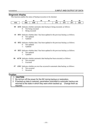
![6.INTERFACE BETWEEN CNC AND PMC B-64305EN/03
- 194 -
6 INTERFACE BETWEEN CNC AND PMC
This section briefly describes the PMC function. It also explains the CNC-PMC interface.
6.1 WHAT IS PMC?...............................................................................................................................195
6.2 PMC SPECIFICATIONS..................................................................................................................202
6.3 OPERATING THE PMC SCREEN..................................................................................................207
6.4 PMC DIAGNOSIS AND MAINTENANCE SCREENS ([PMCMNT])..........................................210
6.5 LADDER DIAGRAM MONITOR AND EDITOR SCREENS ([PMCLAD]) ................................239
6.6 LIST OF ADDRESSES ....................................................................................................................254](https://image.slidesharecdn.com/fanuc0imaintenancemanual-140802043306-phpapp01/85/Fanuc-0i-maintenance-manual-CNC-milling-machine-212-320.jpg)

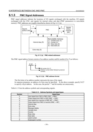

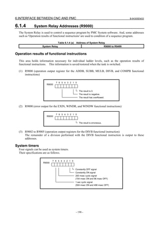
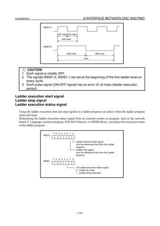
![6.INTERFACE BETWEEN CNC AND PMC B-64305EN/03
- 200 -
RUN
STOP
Execution status of Ladder
Ladder execution status signal
(R9091.2)
Ladder execution start signal
(R9015.0)
Ladder stop signal
(R9015.1)
1
0
1
0
1
0
One ladder
scan cycle
One ladder
scan cycle
(1) Ladder execution start signal (R9015.0)
When directed to start ladder program execution, the system software starts executing the ladder
program, turns on this signal, and keeps it on for the first one scan cycle. Like R9000, this signal
indicates the status of ladder execution corresponding to each ladder execution level. For this
reason, this signal is securely turned on for the first one scan cycle after the start of execution no
matter on what execution level the signal is referenced. This signal is turned on when:
(a) Ladder execution begins at power turn-on.
(b) The [RUN] soft key on the PMC screen is pressed.
(c) FANUC LADDER-III or a ladder editing package directs the ladder to start.
Referencing this signal in a ladder program can detect when ladder execution has begun, making it
possible to program preprocessing related to ladder execution.
CAUTION
Reference this signal only within a ladder program. Do not reference it from an
external system or program as it indicates the status of ladder execution
separately for each ladder execution level.
(2) Ladder stop signal (R9015.1)
When directed to stop ladder program execution, the system software turns off this signal and keeps
it off for the last one scan before stopping ladder program execution. Like R9000, this signal
indicates the status of ladder execution corresponding to each ladder execution level. For this
reason, this signal is securely turned off for the last one scan before the stop of execution no matter
on what execution level the signal is referenced. This signal is turned off when:
(a) The [STOP] soft key on the PMC screen is pressed.
(b) FANUC LADDER-III or a ladder editing package directs the ladder to stop.
(c) On the PMC DATA I/O screen, the ladder program is loaded to the PMC.
(d) FANUC LADDER-III or a ladder editing package stores the ladder program to the PMC.
Referencing this signal in a ladder program can detect when ladder execution stops, making it
possible to program post processing related to ladder execution (that is, preprocessing for ladder
execution stop). Before the ladder is stopped, for example, it is possible to put signals in a proper
state for safety purposes.](https://image.slidesharecdn.com/fanuc0imaintenancemanual-140802043306-phpapp01/85/Fanuc-0i-maintenance-manual-CNC-milling-machine-218-320.jpg)
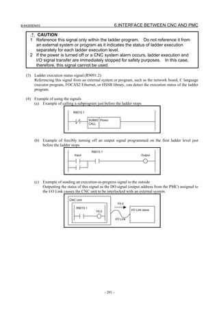
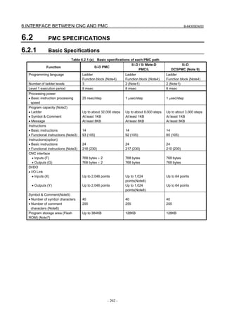
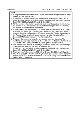
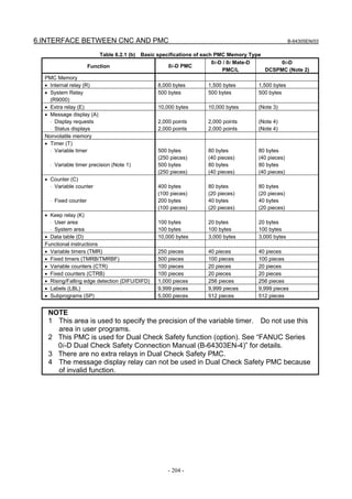
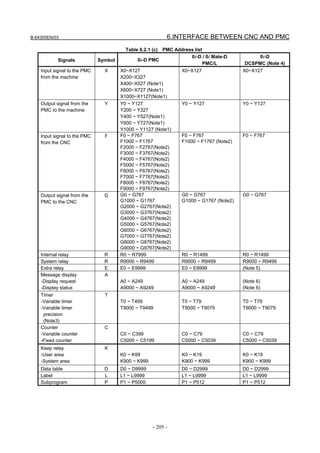
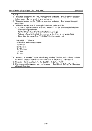
![B-64305EN/03 6.INTERFACE BETWEEN CNC AND PMC
- 207 -
6.3 OPERATING THE PMC SCREEN
The basic configuration of the PMC screen is described below.
OFFSET
SETTING
SYSTEM MESSAGE GRAPH
POS PROG
Function keys
Screen title
[+]
Soft key page
turning key
Return key Message display line
Key entry line
NC status indication
Ladder
execution status
PMC alarmPMC path
• Screen title : Displays the name of a specific submenu of the PMC.
• Ladder execution status : Displays the execution status of the ladder program.
• PMC alarm : Indicates whether any PMC alarm is occurring.
• PMC path : Displays the currently selected PMC.
• Key entry line : Line for entering a numerical value or character key string.
• Message display line : Displays an error or warning message.
• NC status indication : Displays the NC mode, the execution status of the NC program, the
currently selected NC path number.
• Return key : Used to switch from the PMC operation menu to a specific PMC
submenu or from a specific PMC submenu to the main menu of the
PMC.
• Soft key page turning key : Used to turn soft key pages.](https://image.slidesharecdn.com/fanuc0imaintenancemanual-140802043306-phpapp01/85/Fanuc-0i-maintenance-manual-CNC-milling-machine-225-320.jpg)
![6.INTERFACE BETWEEN CNC AND PMC B-64305EN/03
- 208 -
About the PMC screen
When you press the function key and then turn the soft key page by pressing the [+] soft key, the
main menu of the PMC is displayed.
The PMC main menu offers the following three types of submenus, which are respectively used for
specific purposes.
• PMC Maintenance ([PMCMNT] screen)
• PMC Ladder ([PMCLAD] screen)
• PMC Configuration ([PMCCNF] screen)
Each of these PMC submenus is explained below.
(1) PMC Maintenance menu
This menu displays the screens related to the maintenance of the PMC, such as those for PMC signal
status monitoring and traces and for PMC data display and editing.
(2) PMC Ladder menu
This menu displays the screens related to the display and editing of the ladder program.
(3) PMC Configuration menu
This menu displays the screens related to the display and editing of the data other than the ladder
constituting the sequence program, as well as the screen for setting the PMC functions.
This manual briefly describes the screen of each of the PMC maintenance and PMC ladder menus. For
detailed descriptions and the PMC configuration menu, refer to "PMC Programming Manual
(B-64393EN)."](https://image.slidesharecdn.com/fanuc0imaintenancemanual-140802043306-phpapp01/85/Fanuc-0i-maintenance-manual-CNC-milling-machine-226-320.jpg)
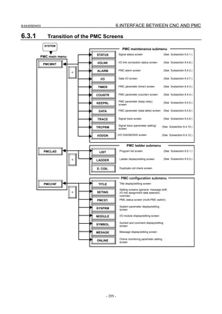
![6.INTERFACE BETWEEN CNC AND PMC B-64305EN/03
- 210 -
6.4 PMC DIAGNOSIS AND MAINTENANCE SCREENS
([PMCMNT])
6.4.1 Monitoring PMC Signal Status ([STATUS] Screen)
The SIGNAL STATUS screen displays the data at all addresses specified in the program. The data of
each address consists of a bit pattern (“0”s and/or “1”s) and a hexadecimal or decimal number at the
rightmost position on a byte-by-byte basis.
The additional information line at the bottom of the screen displays the symbol and comment of the
address on which the cursor is placed. When the cursor is placed on a byte, the byte symbol and
comment are displayed.
Table contents
• ADDRESS: Address referenced by a sequence program
• 0 to 7: Data at each bit position
• HEX: Display of each byte in hexadecimal
• DEC: Display of each byte in decimal
Operation procedure
(1) Press the [STATUS] soft key. The screen shown above appears.
(2) Key in an address whose data to be displayed, then press the [SEARCH] soft key.
(3) The data starting at the input address is displayed as a bit pattern.
(4) To display the data at another address, press the cursor keys, page keys, or [SEARCH] soft key.
(5) To modify the status of a signal, switch to the forced I/O screen by pressing the [FORCE] soft key.
NOTE
The [FORCE] soft key is displayed and usable when the forced I/O function is
enabled. For details, see PMC PROGRAMMING MANUAL (B-64393EN).
Additional information line
Signal status display area
Address Symbol Comment](https://image.slidesharecdn.com/fanuc0imaintenancemanual-140802043306-phpapp01/85/Fanuc-0i-maintenance-manual-CNC-milling-machine-228-320.jpg)
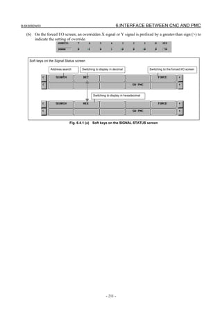
![6.INTERFACE BETWEEN CNC AND PMC B-64305EN/03
- 212 -
6.4.2 Checking PMC Alarms ([ALARM] Screen)
On this screen, an alarm message output from the PMC is displayed. To move to the PMC alarm screen,
press the [ALARM] soft key.
In the alarm message display area, an alarm message output from the PMC is displayed. When many
alarm messages are output to two or more pages, the page keys can be used to switch from one page to
another.
In the page display area to the right of the title, the number of the page currently displaying messages is
indicated.
For information about messages displayed, see Appendix A “Alarm List.”
Alarm message display area
Page display](https://image.slidesharecdn.com/fanuc0imaintenancemanual-140802043306-phpapp01/85/Fanuc-0i-maintenance-manual-CNC-milling-machine-230-320.jpg)
![B-64305EN/03 6.INTERFACE BETWEEN CNC AND PMC
- 213 -
6.4.3 Setting and Displaying Variable Timers ([TIMER] Screen)
This screen is used to set and display timer values for functional instruction variable timers (TMR:SUB 3).
This screen can be used in one of two modes: the simple display mode and the comment display mode.
To move to the TIMER screen, press the [TIMER] soft key.
Simple display mode
Comment display mode (12-soft key display unit)
Comment display
area
Page display
Key input line
Additional information line
Message display line](https://image.slidesharecdn.com/fanuc0imaintenancemanual-140802043306-phpapp01/85/Fanuc-0i-maintenance-manual-CNC-milling-machine-231-320.jpg)

![B-64305EN/03 6.INTERFACE BETWEEN CNC AND PMC
- 215 -
6.4.4 Setting and Displaying Counter Values ([COUNTR] Screen)
This screen is used to set and display the maximum and minimum counter values for functional
instruction counters (CTR: SUB 5). This screen can be used in one of two modes: the simple display
mode and the comment display mode. To move to the COUNTER screen, press the [COUNTR] soft key.
Simple display mode
Comment display mode (12-soft key display unit)
Comment display
area
Page display
Key input line
Additional information line
Message display line](https://image.slidesharecdn.com/fanuc0imaintenancemanual-140802043306-phpapp01/85/Fanuc-0i-maintenance-manual-CNC-milling-machine-233-320.jpg)
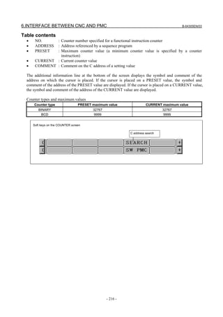
![B-64305EN/03 6.INTERFACE BETWEEN CNC AND PMC
- 217 -
6.4.5 Setting and Displaying Keep Relays ([KEEPRL] Screen)
This screen is used for setting and displaying the Keep Relays. To move to the KEEP RELAY screen,
press the [KEEPRL] soft key.
Contents of the table
• ADDRESS : Address referred by sequence Program
• 0 to 7 : Contents of each bit
• HEX : Value of the byte data in hexadecimal notation
The additional information line at the bottom of the screen displays the symbol and comment of the
address on which the cursor is placed. When the cursor is placed on a byte, the byte symbol and
comment are displayed.
Since Keep Relay is nonvolatile memory, the contents are not lost even if you turn off the power.
The Keep Relay area consists of parts as follows.
0i-D PMC
0i-D /0i Mate-D
PMC/L
0i-D
DCSPMC
User area K0 to K99 K0 to K19 K0 to K19
Area for management software K900 to K999 K900 to K999 K900 to K999
CAUTION
If the area for the PMC management software is protected by the programmer
protection function, the area is not displayed on the KEEP RELAY screen. For
details, see PMC PROGRAMMING MANUAL (B-64393EN).
Page display
Additional information line
Key input line Message display line](https://image.slidesharecdn.com/fanuc0imaintenancemanual-140802043306-phpapp01/85/Fanuc-0i-maintenance-manual-CNC-milling-machine-235-320.jpg)
![6.INTERFACE BETWEEN CNC AND PMC B-64305EN/03
- 218 -
6.4.6 Setting and Displaying Data Tables ([DATA] Screen)
There are two data table types (DATA TABLE CONTROL and DATA TABLE). To move to the data
screen, press the [DATA] soft key.
DATA TABLE CONTROL screen ([List] screen)
Pressing the [DATA] soft key displays the DATA TABLE CONTROL screen for data table management.
This screen can be used in one of two modes: the simple display mode and the comment display mode.
Simple display mode
Comment display mode (12-soft key display unit)
Comment
display area
Page display
Display of the
number of groups
Additional information line
Key input line Message display line](https://image.slidesharecdn.com/fanuc0imaintenancemanual-140802043306-phpapp01/85/Fanuc-0i-maintenance-manual-CNC-milling-machine-236-320.jpg)
![B-64305EN/03 6.INTERFACE BETWEEN CNC AND PMC
- 219 -
- Table contents
• GROUP TABLE COUNT : Number of data items in the data table
• NO. : Group number
• ADDRESS : Data table start address
• PARAMETER : Data table control parameter
• TYPE : Data length (0 = 1 byte, 1 = 2 bytes, 2 = 4 bytes, 3 = bit)
• DATA : Number of data items in each data table
• COMMENT : Comment on the start D address of each group
The additional information line at the bottom of the screen displays the symbol and comment of the
address on which the cursor is placed. When the cursor is placed on the PARAMETER, TYPE, or DATA
column, the current setting is displayed.
The ADDRESS column displays the start address of a data table. Multiple groups may share an address.
When the [SYMBOL] soft key is pressed, the symbol of the start address is displayed.
NOTE
The data table control parameters have the following meanings:
0: Binary format
1: BCD format (Bits 2 and 3 are invalid.)
0: Without input protection
1: With input protection
0: Binary or BCD format (Bit 0 is valid.)
1: Hexadecimal format (Bits 0 and 3 are invalid.)
0: Signed (valid only when bits 0 and 2 are set to 0)
1: Unsigned (valid only when bits 0 and 2 are set to 0)
#7 #6 #5 #4 #3 #2 #1 #0
NOTE
1 When data table control data is protected by the programmer protection function,
the data table control data screen is not displayed. For details, see PMC
PROGRAMMING MANUAL (B-64393EN).
2 When PMC parameters are output using the I/O screen (see Subsection 6.4.7,
“Data Input/Output ([I/O] Screen)”), only the data of an address D area set in the
data table control data is output from the data table screen. The data of an
address D area not set in the data table control data is not output.](https://image.slidesharecdn.com/fanuc0imaintenancemanual-140802043306-phpapp01/85/Fanuc-0i-maintenance-manual-CNC-milling-machine-237-320.jpg)
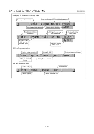
![B-64305EN/03 6.INTERFACE BETWEEN CNC AND PMC
- 221 -
DATA TABLE screen ([ZOOM] screen)
If the data table control data is specified, pressing the [ZOOM] soft key on the data table control data
screen displays the data table setting screen. This screen can be used in one of three modes: the simple
display mode, the comment display mode, and the bit display mode.
Simple display mode
Comment display mode (12-soft key display unit)
Comment display area
Group
information line
Page display
Additional information line
Key input line Message display line](https://image.slidesharecdn.com/fanuc0imaintenancemanual-140802043306-phpapp01/85/Fanuc-0i-maintenance-manual-CNC-milling-machine-239-320.jpg)
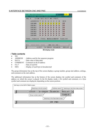
![B-64305EN/03 6.INTERFACE BETWEEN CNC AND PMC
- 223 -
6.4.7 Data Input/Output ([I/O] Screen)
To move to the I/O screen, press the [I/O] soft key.
On this screen, sequence programs, PMC parameters and PMC message data for multi-language display
can be written to the specified device, read from the device, and compared. The query selection cursor,
which moves vertically from one question to another, is displayed, as is the option selection cursor, which
moves horizontally from one option to another.
The following types of devices can be used for input/output. The desired device type can be selected by
positioning the query selection cursor to "DEVICE" and moving the option selection cursor to that type.
• MEMORY CARD : Data can be output to and input from a memory card.
• FLASH ROM : Data can be output to and input from flash ROM.
• FLOPPY : Data can be output to and input from handy files or floppy cassettes.
• OTHERS : Data can be output to and input from other general-purpose RS-232C
input/output devices.
In STATUS in the lower part of the screen, a detailed explanation of execution and the execution status
are displayed. During write, read, and comparison, the size of the data already transferred is indicated as
the execution (intermediate) result.](https://image.slidesharecdn.com/fanuc0imaintenancemanual-140802043306-phpapp01/85/Fanuc-0i-maintenance-manual-CNC-milling-machine-241-320.jpg)
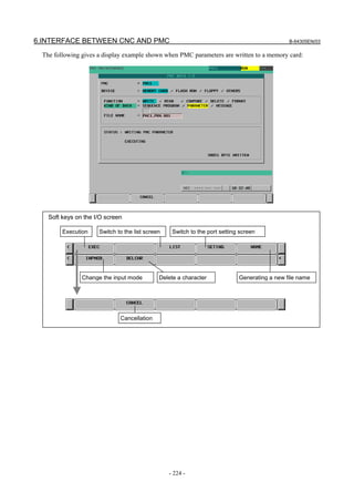
![B-64305EN/03 6.INTERFACE BETWEEN CNC AND PMC
- 225 -
6.4.8 Displaying I/O Link Connection Status ([I/OLNK] Screen)
I/O LINK MONITOR screen shows the types and the ID codes of I/O Units that are connected to I/O
Link in order of Group number.
To switch the screen display to the I/O LINK MONITOR screen, press the [I/OLNK] soft key.
Table 6.4.8 Displayed type and true type of I/O Units
Displayed I/O Unit ID True I/O Unit
CONNECTION UNIT 80 Connection Unit
OPERATOR PANEL 82 Connection Unit for Operators Panel
I/O-B3 83 I/O B3
IO UNIT-MODEL A 84
86
87
I/O Unit-MODEL A
PLC SERIES 90-30 45 PLC SERIES 90-30
POWER MATE / I/O LINK BETA 4A Power Mate or I/O Link β
SERIES 0 50 Series 0
OPERATOR I/F BOARD (MPG1) 53 Machine Operators Panel Interface
LINK CONNECTION UNIT 96 I/O Link Connecting Unit
I/O UNIT-MODEL B 9E I/O Unit-MODEL B
R-J MATE 61 R-J Mate
CONNECTOR PANEL MODULE A9 I/O module for connector panel
OPERATOR PANEL A1 AA I/O module for operator's panel
OPERATOR I/F BOARD (MPG3) 6B Operator Interface(with MPG)
FRC DIF B0 DIF Board for ROBOCUT
FRC MIF B1 MIF Board for ROBOCUT
I/O CARD B2 I/O board
ROBOSHOT I/O CARD A B3 I/O for ROBOSHOT
PROCESS I/O FA B5 Process I/O for robot controller
PROCESS IO 89 Process I/O for robot controller
I/O LINK ADAPTER 8B I/O Link adapter
ROBOT CONTROLLER 52 Controller for robot
GE Fanuc PLC 54 GE Fanuc PLC
OPERATOR PANEL 95 I/O for Series 0
I/O Unit type
Channel number
I/O Unit ID code
Group number](https://image.slidesharecdn.com/fanuc0imaintenancemanual-140802043306-phpapp01/85/Fanuc-0i-maintenance-manual-CNC-milling-machine-243-320.jpg)
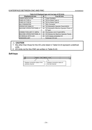
![B-64305EN/03 6.INTERFACE BETWEEN CNC AND PMC
- 227 -
6.4.9 Signal Trace Function ([TRACE] Screen)
SIGNAL TRACE screen (initial screen)
Before trace operation can be executed, the trace parameters must be set. Press the [TRCPRM] soft key to
switch the screen display to the trace parameter setting screen.
By setting the PMC setting screen, the trace function can be automatically started after the power is
turned on. In this case as well, the trace parameters must be set beforehand.
NOTE
For the setting to automatically start the trace function after the power is turned
on, see Subsection 6.4.11.2.](https://image.slidesharecdn.com/fanuc0imaintenancemanual-140802043306-phpapp01/85/Fanuc-0i-maintenance-manual-CNC-milling-machine-245-320.jpg)
![6.INTERFACE BETWEEN CNC AND PMC B-64305EN/03
- 228 -
6.4.10 Setting of Trace Parameter ([TRCPRM] Screen)
On the trace parameter setting screen, a sampling condition can be set. The screen consists of two pages.
Use the page keys to switch between the pages.
Trace parameter setting screen (first page)
(a) SAMPLING/ MODE
Determines the sampling mode.
• TIME CYCLE : Samples at every specified cycle time.
• SIGNAL TRANSITION : Monitors the signal at a set cycle and samples when the signal
makes a transition.
(b) SAMPLING/ RESOLUTION
The resolution of sampling is inputted. The default value is the minimum sampling resolution (msec),
which varies depending on the CNC.
Setting range: Minimum sampling resolution to 1000 (msec)
An input value is rounded off to a multiple of the minimum sampling resolution (msec) which is
closest to but not greater than the input value.
(c) SAMPLING/ TIME
This parameter is displayed when "TIME CYCLE" is set on "SAMPLING/ MODE". The execution
time of trace is inputted. The value of "SAMPLING/ RESOLUTION" or the number of specified
signal address changes the range of the value that is able to input. The range is displayed on the right
side.
(d) SAMPLING/ FRAME
This parameter is displayed when "SIGNAL TRANSITION" is set on SAMPLING/ MODE". The
number of sampling is inputted. The value of "SAMPLING/ RESOLUTION" or the number of
specified signal addresses changes the range of the value that is able to input. The range is displayed
on the right side.
(e) STOP CONDITION
Determines the condition to stop the trace.
• NONE : Does not stop the tracing automatically.
• BUFFER FULL : Stops the tracing when the buffer becomes full.
• TRIGGER : Stops the tracing by trigger.
(f) STOP CONDITION/ TRIGGER/ ADDRESS
When "TRIGGER" is set on "STOP CONDITION", this parameter is enabled. Input signal address
or symbol name as stop trigger.](https://image.slidesharecdn.com/fanuc0imaintenancemanual-140802043306-phpapp01/85/Fanuc-0i-maintenance-manual-CNC-milling-machine-246-320.jpg)
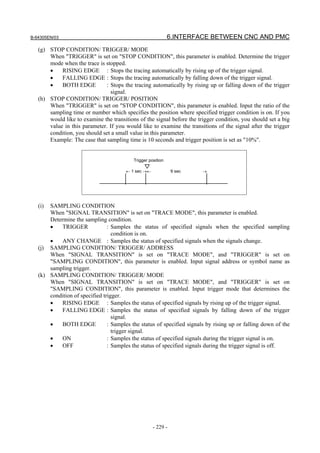
![6.INTERFACE BETWEEN CNC AND PMC B-64305EN/03
- 230 -
TRACE PARAMETER SETTING screen (page 2)
In page 2 of the PARAMETER SETTING screen, you can set the addresses or symbols that should be
sampled.
Trace parameter setting screen (second page)
(a) Setting addresses
In case of inputting discrete bit addresses, any bit address can be inputted.
Moreover, when you input byte address, all bits of the address (bits 0 to 7) are set automatically.
Maximum 32 points of signal address can be inputted.
NOTE
Increasing the number of the signal address changes the capacity of
"SAMPLING/ TIME" or "SAMPLING/ FRAME" in page 1. If the capacity is
changed, the following warning message is displayed. (The "n" on the message
means the maximum value that is able to input.)
a) In case of "TIME CYCLE" mode
"SAMPLING TIME IS REDUCED TO n SEC."
b) In case of "SIGNAL TRANSITION" mode
"SAMPLING FRAME IS REDUCED TO n."
(b) Soft keys
Soft keys on the setting screen of sampling address are as follows
• [DELETE] : Clears the value of the edit box on the cursor.
• [SYMBOL]/[ADRS] : Changes the address display to the symbol display. However, display of
the address that is not defined the symbol does not change. This soft
key also changes to "ADDRESS". The following soft keys are
displayed.
• [MV.UP] : Exchanges the signal indicated the cursor for the signal above one line.
• [MV.DWN] : Exchanges the signal indicated the cursor for the signal below one line.
• [DELALL] : Clears all of the value of the edit box.](https://image.slidesharecdn.com/fanuc0imaintenancemanual-140802043306-phpapp01/85/Fanuc-0i-maintenance-manual-CNC-milling-machine-248-320.jpg)

![6.INTERFACE BETWEEN CNC AND PMC B-64305EN/03
- 232 -
6.4.11 Execution of Trace
After the trace parameters are set, a trace operation can be started by pressing the [(OPRT)] soft key and
the [START] soft key on the SIGNAL TRACE screen. The following is the screen examples of the trace
execution by "TIME CYCLE" mode and "SIGNAL TRANSITION" mode.
Execution of trace screen (TIME CYCLE mode)
Execution of trace screen (SIGNAL TRANSITION mode)
The result of trace is immediately displayed during execution of the trace.
When the stop conditions that is set in parameter setting screen is satisfied the execution is finished.
Pressing [STOP] soft key aborts the execution. In "SIGNAL TRANSITION" mode, graphic display is not
refreshed until any signal for sampling trigger changes.](https://image.slidesharecdn.com/fanuc0imaintenancemanual-140802043306-phpapp01/85/Fanuc-0i-maintenance-manual-CNC-milling-machine-250-320.jpg)
![B-64305EN/03 6.INTERFACE BETWEEN CNC AND PMC
- 233 -
6.4.11.1 Operation after execution of trace
When the execution is finished, the result of trace is displayed. The followings are the screen examples of
trace by "TIME CYCLE" and "SIGNAL TRANSITION" mode.
Result of trace screen (TIME CYCLE mode)
Result of trace screen (SIGNAL TRANSITION mode)
The cursor indicating current position is initially displayed on the original point (0 point). The position of
the cursor is displayed in "CURSOR POSITION" in the upper of the screen. The cursor can move
horizontally with the <←> or <→> key. After the execution, following operation is enabled.
(a) Scroll of screen
• Cursor up/down key and Page up/down key
Enables the vertical scroll for the specified signal
• Cursor right/left key, [NEXT>>] soft key and [<< PREV] soft key
Enables the horizontal scroll of the graph.](https://image.slidesharecdn.com/fanuc0imaintenancemanual-140802043306-phpapp01/85/Fanuc-0i-maintenance-manual-CNC-milling-machine-251-320.jpg)
![6.INTERFACE BETWEEN CNC AND PMC B-64305EN/03
- 234 -
(b) Automatic calculation of the selected range
Pressing [MARK] soft key marks the current position and displays the mark cursor.
If the mark cursor duplicates with the current position cursor, the current position cursor has priority
of display. The "MARK POSITION" that shows the position of the mark cursor and "RANGE" that
shows the range between the mark cursor and the current position cursor are displayed in the upper
of screen.
Moving the current position cursor changes these values. Pressing [MARK] again releases the select
range mode.
Result of trace screen (Mark cursor display)
(c) Zoom in/Zoom out of waveform
Pressing [Z.IN] soft key magnifies the display of chart. Pressing [Z.OUT] soft key reduces the
display of chart. Pressing these soft keys also change the scale value of the graduation on the graph.
When trace is just finished, the default zooming level was the most magnified level. In "ZOOM
OUT" mode, " " is displayed as following screen example when the transitions of signal cannot be
expressed accurately enough. The limitation of "ZOOM OUT" displays all of result of the trace in
one page.
Result of trace screen (Zoom out display)](https://image.slidesharecdn.com/fanuc0imaintenancemanual-140802043306-phpapp01/85/Fanuc-0i-maintenance-manual-CNC-milling-machine-252-320.jpg)
![B-64305EN/03 6.INTERFACE BETWEEN CNC AND PMC
- 235 -
(d) Exchange of sampling signal
Pressing [MV.UP] soft key exchanges the signal indicated by the signal cursor for the signal one line
above. Pressing [MV.DWN] soft key exchanges the signal indicated by the signal cursor for the
signal one line below. The result of the operation is cancelled by the execution of trace or putting the
power off. When you would like to preserve the order of displayed signals against the executing or
powering off, please change the order on "SAMPLING ADDRESS" screen.
6.4.11.2 Automatic start of trace setting
Trace execution is automatically started after power-on by setting a PMC setting data.
• TRACE START = MANUAL/AUTO
NOTE
For details of the method of setting PMC setting data, see PMC
PROGRAMMING MANUAL (B-64393EN).](https://image.slidesharecdn.com/fanuc0imaintenancemanual-140802043306-phpapp01/85/Fanuc-0i-maintenance-manual-CNC-milling-machine-253-320.jpg)
![6.INTERFACE BETWEEN CNC AND PMC B-64305EN/03
- 236 -
6.4.12 MONITORING I/O DIAGNOSIS ([I/ODGN] SCREEN)
In I/O Diagnosis screen, you can check the status of each I/O variable. You can also check the
configuration of I/O devices and the communication status with them.
(1) GRP (GROUP)
To include a specific string which means a kind of signals in a part of symbol string, these signals on
I/O diagnosis screen are classified and you can easy to understand the status of signals.
The group names of the I/O variables are displayed, which are extracted (Max. 4 chars) out of their
symbol names as configured in “GROUP FORMAT” in the setting screen.
The groups to be displayed can be specified by soft key.
[ALLGRP] All groups are displayed.
[GROUP] The group entered by key or the group under the cursor is selected to be displayed.
(2) PROG.SYMBOL (SYMBOL)
The symbol names of the I/O variables are displayed.
(3) ADDRESS
The actual locations of I/O variables are displayed.
(4) VALUE
The current values of I/O variables are displayed as signed decimal, according to the data type of
them (i.e. BOOL, BYTE, WORD, and DWORD).
(5) I/O INFORMATION
The information related to I/O network is displayed in the display format below:
<I/O type><Network type> : <Network address> : <status>
Listing order
Additional information](https://image.slidesharecdn.com/fanuc0imaintenancemanual-140802043306-phpapp01/85/Fanuc-0i-maintenance-manual-CNC-milling-machine-254-320.jpg)
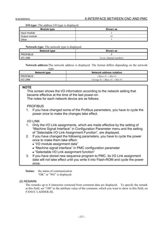
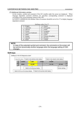
![B-64305EN/03 6.INTERFACE BETWEEN CNC AND PMC
- 239 -
6.5 LADDER DIAGRAM MONITOR AND EDITOR SCREENS
([PMCLAD])
The PMC LADDER menu contains the screens related to PMC Ladder diagrams, such as the PROGRAM
LIST screen and the LADDER DIAGRAM MONITOR/EDITOR screens.
You can switch to the PMC LADDER menu by operating on the "SYSTEM" key and then the
[PMCLAD] soft key.
LIST
LADDER
PMCLAD
<
Program list screen
Ladder diagram Monitor / Editor
screen
PMC LADDER menu
SYSTEM
D. COIL Duplicate coil check screen
PMC main menu
Pressing the [LADDER] soft key causes the sequence program to be dynamically displayed, allowing you
to monitor operation. The editor screen allows you to make changes to relay and functional instructions in
the sequence program to change the operation of the sequence program.
The ladder diagram display/editor functions consist of the following screens:
(1) Ladder diagram display screen (LADDER DIAGRAM MONITOR screen)
Displays ladder diagrams to monitor the current states of relays, coils, and so on.
(2) COLLECTIVE MONITOR screen
Displays only a selected ladder net to monitor the current states of relays, coils, and so on.
(3) LADDER DIAGRAM EDITOR screen
Allows you to edit a ladder diagram in units of nets.
(4) NET EDITOR screen
Allows you to edit a single net in a ladder diagram.
(5) PROGRAM LIST VIEWER screen
Allows you to select the subprogram to be displayed on the LADDER DIAGRAM MONITOR
screen.
(6) PROGRAM LIST EDITOR screen
Allows you to edit a ladder program in units of subprograms. Also allows you to select the
subprogram to be edited on the LADDER DIAGRAM EDITOR screen.
(7) SUBPROGRAM LIST VIEWER screen
Displays a list of called subprograms and subprogram display history.
The following screens can be called from the LADDER DIAGRAM EDITOR screen:
(8) FUNCTIONAL INSTRUCTION DATA TABLE VIEWER screen
Allows you to view the contents of the data table for a data table attached functional instruction.
(9) FUNCTIONAL INSTRUCTION DATA TABLE EDITOR screen
Allows you to edit the contents of the data table for a data table attached functional instruction.
NOTE
You can protect these screens by using the programmer protection function. For
details, see PMC PROGRAMMING MANUAL (B-64393EN).
You can change between screens as shown in the figure below.](https://image.slidesharecdn.com/fanuc0imaintenancemanual-140802043306-phpapp01/85/Fanuc-0i-maintenance-manual-CNC-milling-machine-257-320.jpg)
![6.INTERFACE BETWEEN CNC AND PMC B-64305EN/03
- 240 -
[SWITCH]
Edit function
[LIST]
[EXIT] [ZOOM]
PROGRAM LIST
EDITOR screen
LADDER DIAGRAM
EDITOR screen
NET EDITOR screen
[CREATE]
[ZOOM]
[LIST]
[ZOOM]
[ZOOM]
[EDIT]
COLLECTIVE MONITOR screen
[LIST][LADDER]
[<][<]
[PMCLAD][<]
PMC main menu
PMC LADDER menu
Display function
(monitor)
[EXIT]
[SPLIST]
[LADDER]
[LIST]
SUBPROGRAM LIST
VIEWER screen [LIST]
[BACK]
LADDER DIAGRAM
MONITOR screen
[BACK]
PROGRAM LIST
VIEWER screen
[ZOOM]
[BACK]
[ZOOM]
Fig. 4.5 Changes between screens
NOTE
The [EDIT] soft key on the LADDER DIAGRAM MONITOR screen is displayed so
that it is available if the programmer protection function is enabled. While the
online monitor function is enabled, you cannot move to the LADDER DIAGRAM
EDITOR screen. (To stop the online monitor function, change the settings of
"RS-232C" and "HIGH SPEED" to "NOT USE").
6.5.1 Displaying a Program List ([LIST] Screen)
The PROGRAM LIST VIEWER screen shows program information such as the program size.
Ladder preview display area
Message display lineKey input line
Program number area
Size area
SP area](https://image.slidesharecdn.com/fanuc0imaintenancemanual-140802043306-phpapp01/85/Fanuc-0i-maintenance-manual-CNC-milling-machine-258-320.jpg)
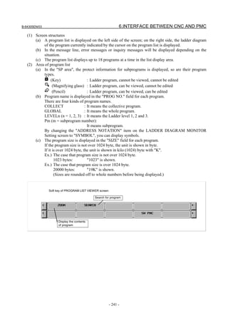
![6.INTERFACE BETWEEN CNC AND PMC B-64305EN/03
- 242 -
6.5.2 Monitoring Ladder Diagrams ([LADDER] Screen)
LADDER DIAGRAM MONITOR screen shows the on/off status of contacts and coils, and the contents
of address specified for parameter of functional instructions.
From the PMC LADDER menu, you can switch to the LADDER DIAGRAM MONITOR screen by using
the [LADDER] soft key. You can use following operation at this screen, including "Forced I/O function
(Forcing mode)", by which you can force the relay or the address parameters of functional instructions to
a new status or value.
• Switch subprogram to show [LIST]
• Search for address or others [SEARCH]
• Show data table of functional instructions [TABLE]
• Go to COLLECTIVE MONITOR Screen [SWITCH]
• Forced I/O function (Forcing mode) "number" + INPUT key
(1) Screen structures
(a) Title information (REMARKS) of the LADDER Program, the current subprogram, and the
current position information of the Diagram displayed in this screen, are displayed above the
LADDER Diagram.
When you select a subprogram to be displayed, range for search function is indicated at right of
the top line as "LOCAL" or "GLOBAL". In case of "LOCAL", the range for search function is
restricted within the current subprogram. In case of "GLOBAL", on the other hand, search
function searches whole of LADDER program, and switch current subprogram automatically
according to the result of searching.
(b) In the additional information line near the bottom of the screen, the following information of
the address under the cursor is displayed when the cursor is shown.
• Net number of the net with the cursor
• Address and its symbol and comment information
• Current value
(c) In the message line, error messages or inquiry messages will be displayed depending on the
situation.
(d) In the area for LADDER diagrams, 8 × 8, 8 × 6, 8 × 4, 7 × 8, 7 × 6, and 7 × 4 relays can be
displayed (horizontally and vertically). For details, see PMC PROGRAMMING MANUAL
(B-64393EN).
(e) The gage indicating the current display position in relation to the whole Ladder program is
displayed at the right end of the screen.
Key input line
Message line
Additional information line
Area for LADDER Diagram
Title information (REMARKS)Current subprogram](https://image.slidesharecdn.com/fanuc0imaintenancemanual-140802043306-phpapp01/85/Fanuc-0i-maintenance-manual-CNC-milling-machine-260-320.jpg)
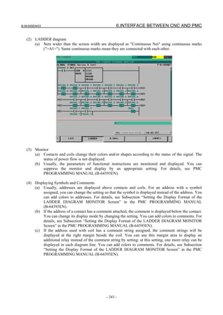
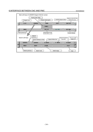
![B-64305EN/03 6.INTERFACE BETWEEN CNC AND PMC
- 245 -
6.5.3 Editing Ladder Programs
At LADDER DIAGRAM EDITOR screen you can edit LADDER program to change its behavior.
To switch LADDER DIAGRAM EDITOR screen, press [EDIT] soft key at LADDER DIAGRAM
MONITOR screen.
Following operations are available at LADDER DIAGRAM EDITOR screen.
• Delete by net [DELETE]
• Move by net [CUT] & [PASTE]
• Copy by net [COPY] & [PASTE]
• Change address of contacts and coils "bit address" + INPUT key
• Change parameters of functional instructions "number" or "byte address" + INPUT key
• Add new net [CREATE]
• Change construction of net [ZOOM]
• Make changes effective [UPDATE]
• Abandon changes [RESTRE]
• Cancel edit [CANCEL]
LADDER DIAGRAM EDITOR screen](https://image.slidesharecdn.com/fanuc0imaintenancemanual-140802043306-phpapp01/85/Fanuc-0i-maintenance-manual-CNC-milling-machine-263-320.jpg)
![6.INTERFACE BETWEEN CNC AND PMC B-64305EN/03
- 246 -
CAUTION
1 You can edit ladder programs regardless of whether they are active or not. To
execute a ladder program with the results of editing being reflected, you must
update the ladder program. To do this, press the [UPDATE] soft key, or update
the program when exiting from the LADDER DIAGRAM EDITOR screen. For
details of the method of protecting editing, see “PMC PROGRAMMING MANUAL
(B-64393EN).”
2 After you have edited a sequence program, the results of editing will be lost if the
power is turned off without first writing the edited sequence program to flash
ROM.
Write the sequence program to flash ROM on the I/O screen. If you set "WRITE
TO F-ROM(EDIT)" to "YES" on the general functions' setting parameter screen, a
confirmation message will be displayed, prompting you to ask whether to write a
sequence program to flash ROM after the end of editing. For details of this
setting, see “PMC PROGRAMMING MANUAL (B-64393EN).”
(1) Screen structures
(a) It is basically same with LADDER DIAGRAM MONITOR screen, except that no monitor
displays of relays and parameters of functional instructions are displayed.
(b) At right side of LADDER Diagram area, a position bar is always displayed, which indicates
screen position within current subprogram: in LADDER DIAGRAM MONITOR screen, this
position bar is exclusively displayed with comments of write coil. Sometimes, this position bar
hides a part of write coil comments.
(2) LADDER Diagram
(a) Style of LADDER Diagram is basically same with LADDER DIAGRAM MONITOR screen,
except that functional instructions are drawn always in "COMPACT" format that has no
monitor displays.
(b) Cursor is shown always. And the net, which will be an object of following editing operations, is
emphasized in screen.
Abandon changes Setting screen
Cancel edit ExitRun/stop LADDER
Soft keys of LADDER Diagram Editor screen
Make changes
effectiveChange address
Display address
map display
screen
Select net Copy netDelete net Cut net Paste net
Add net
Edit new net
Change to Search soft keysProgram List Automatic input](https://image.slidesharecdn.com/fanuc0imaintenancemanual-140802043306-phpapp01/85/Fanuc-0i-maintenance-manual-CNC-milling-machine-264-320.jpg)
![B-64305EN/03 6.INTERFACE BETWEEN CNC AND PMC
- 247 -
WARNING
You have to pay special attention to modify running LADDER program. If you
modify LADDER program in wrong way, or update LADDER program with the
machine in improper status, it may cause unexpected reaction of the machine.
You have to make it sure that modifications you make on LADDER program is
appropriate, machine is in proper status, and nobody is near the machine, when
you update LADDER program.
6.5.3.1 NET EDITOR Screen
At NET EDITOR screen, you can create new net, and modify existing net.
• Changing existing nets
If you move a net with the [ZOOM] soft key, you will enter a mode (Modify mode) in which you
can add changes to the net currently indicated by the cursor.
• Adding a new net
When [CREATE] soft key is used, this screen is in "New mode" to create new net from nothing.
Following operations are available at this screen:
• Place new contacts and coils "bit address" + [ ], [ ], etc.
• Change type of contacts and coils [ ], [ ], etc.
• Place new functional instructions [FUNC]
• Change type of functional instructions [FUNC]
• Erase contacts, coils, and functional instructions [ ]
• Draw/erase connecting lines [ ]/[ ], [ ], [ ]
• Edit data table of functional instructions [TABLE]
• Insert line/column [INSLIN], [INSCLM], [APPCLM]
• Change address of contacts and coils "bit address" + INPUT key
• Change parameters of functional instructions "number" or "byte address" + INPUT key
• Abandon modifications [CANCEL]
• Restore the net to the state it was before editing [RESTRE]
Fig. 6.5.3.1 (a) Structure of the NET EDITOR screen](https://image.slidesharecdn.com/fanuc0imaintenancemanual-140802043306-phpapp01/85/Fanuc-0i-maintenance-manual-CNC-milling-machine-265-320.jpg)
![6.INTERFACE BETWEEN CNC AND PMC B-64305EN/03
- 248 -
(1) Screen structures
(a) It is basically same with LADDER DIAGRAM EDITOR screen, except that only one net is in
this screen, and that position bar at right edge of screen does not appear at this screen.
(b) Current edit mode is indicated at right of the top line as "NEW MODE" or "MODFY MODE".
When [ZOOM] soft key at LADDER DIAGRAM EDITOR screen is used to reach NET
EDITOR screen, the screen is in Modify mode, and when [CREATE] soft key is used, it is in
New mode.
(c) Current net number is displayed at right of the top line. The net number is same with the net
number in previous LADDER DIAGRAM EDITOR screen.
(d) NET EDITOR screen expands image of net horizontally for a wider net according to its width,
while LADDER DIAGRAM MONITOR/EDITOR screen folds nets wider than screen width.
When net width is expanded over screen width, attempt to move cursor out of screen will scroll
net image to the direction.
The net of maximum size occupies area of 1024 elements, but actually available area may be
little less for internal use according to the internal condition: "element" means the space that is
occupied by single relay.
Soft keys of Net Editor screen
Edit next netAbandon changes
Delete
B contact Inverted coil
Right vertical
connection
A contact Normal coil
Horizontal
connection
Functional
instructions
Left vertical
connection
Data table
Insert column
Reset coil
Insert line Add column Cancel edit Exit
Set coil
Automatic
input](https://image.slidesharecdn.com/fanuc0imaintenancemanual-140802043306-phpapp01/85/Fanuc-0i-maintenance-manual-CNC-milling-machine-266-320.jpg)
![B-64305EN/03 6.INTERFACE BETWEEN CNC AND PMC
- 249 -
6.5.4 PROGRAM LIST EDITOR Screen
At PROGRAM LIST EDITOR screen you can create new program and delete a program in addition to
the function of PROGRAM LIST VIEWER screen. To reach this screen, press [LIST] soft key at
LADDER DIAGRAM EDITOR screen. Following operations are available at PROGRAM LIST
EDITOR screen. For more detail of these operations, see the descriptions of each key to operate.
• Create new program[NEW]
• Delete a program [DELETE]
Fig. 6.5.4 PROGRAM LIST EDITOR screen
On the PROGRAM LIST EDITOR screen, a preview of the editor screen for the ladder program currently
positioned by the cursor on the program list is displayed on the right of the screen.
Soft keys of Program List Editor screen
Display the contents of program Add new program
Search for program Delete a program](https://image.slidesharecdn.com/fanuc0imaintenancemanual-140802043306-phpapp01/85/Fanuc-0i-maintenance-manual-CNC-milling-machine-267-320.jpg)
![6.INTERFACE BETWEEN CNC AND PMC B-64305EN/03
- 250 -
6.5.5 Collective Monitor Function
The COLLECTIVE MONITOR screen allows you to specify the ladder net containing the coils to be
monitored, so that you can monitor only the necessary ladder net.
The COLLECTIVE MONITOR screen can be called in either of the following ways:
(1) Calling from the PROGRAM LIST VIEWER screen
On the program list screen, move the cursor to the "COLLECT" program position, then press the
[ZOOM] soft key.
Fig. 6.5.5 (a) PROGRAM LIST VIEWER screen
(2) Calling from the LADDER DIAGRAM MONITOR screen
On the LADDER DIAGRAM MONITOR screen, press the [SWITCH] soft key.
Fig. 6.5.5 (b) LADDER DIAGRAM MONITOR screen](https://image.slidesharecdn.com/fanuc0imaintenancemanual-140802043306-phpapp01/85/Fanuc-0i-maintenance-manual-CNC-milling-machine-268-320.jpg)
![6.INTERFACE BETWEEN CNC AND PMC B-64305EN/03
- 252 -
(3) Picking up a ladder net on the COLLECTIVE MONITOR screen
You can pick up a ladder net from the COLLECTIVE MONITOR screen. The procedure for picking
up a ladder net is as described below.
(a) Address specification
(i) Enter the address to monitor (for example, R10.1).
(ii) Press the [PICKUP] soft key.
(iii) The net in which a coil uses the address specified in (i) will be picked up and loaded at the
beginning of the screen.
(b) Specification of an address from a ladder net on the screen
(i) Move the cursor to a relay on the ladder net that uses the address you want to monitor.
(ii) Press the [PICKUP] soft key.
(iii) The net in which a coil uses the address specified in (i) will be picked up and loaded at the
beginning of the screen, and the cursor moves to the specified coil position.
Fig. 6.5.5.1 (c) COLLECTIVE MONITOR screen
(4) Picking up a ladder net from the LADDER DIAGRAM MONITOR screen
You can pick up a ladder net from the LADDER DIAGRAM MONITOR screen. The procedure for
picking up a ladder net is as described below.
(a) From the LADDER DIAGRAM MONITOR screen, press the [SEARCH] soft key to display
the soft keys for search.
(b) Move the cursor to the ladder net to pick up.
(c) Press the [PICKUP] soft key to pick up and load the net specified in (b) at the beginning of the
COLLECTIVE MONITOR screen.
(d) For the ladder net picked up and loaded into the COLLECTIVE MONITOR screen, the " "
mark is displayed at the left end of the net.](https://image.slidesharecdn.com/fanuc0imaintenancemanual-140802043306-phpapp01/85/Fanuc-0i-maintenance-manual-CNC-milling-machine-270-320.jpg)
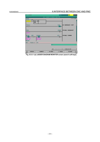
![6.INTERFACE BETWEEN CNC AND PMC B-64305EN/03
- 254 -
6.6 LIST OF ADDRESSES
Interface addresses among CNC and PMC are as follows:
[Example of controlling one path using one PMC]
G0000~
F0000~
X000~
Y000~
CNC PMC Machine tool
[Example of controlling two paths using one PMC]
G0000~
F0000~
X000~
Y000~
CNC
PMC Machine tool
Path 1
G1000~
F1000~Path 2
- Expression of signals
Address Symbol (#0 to #7 indicates bit position)
7 6 5 4 3 2 1 0
Fn000 OP SA STL SPL RWD
In an item where both T series and M series are described, some signals are covered with shade ( )
in the signal address figure as shown below. This means either lathe system or machining center system
does not have this signal. Upper part is for lathe system and lower part is for machining center system.
7 6 5 4 3 2 1 0
*CDZ T series
Gn053 ROVLP UINT TMRON
M series
[Example 1]
The figure above indicates *CDZ is provided only for the T series while the other signals for both
the T series M series.
7 6 5 4 3 2 1 0
T series
Gn040
OFN9 OFN8 OFN7 OFN6 M series
[Example 2]
Signals OFN6 to OFN9 are for M series only.](https://image.slidesharecdn.com/fanuc0imaintenancemanual-140802043306-phpapp01/85/Fanuc-0i-maintenance-manual-CNC-milling-machine-272-320.jpg)
![B-64305EN/03 6.INTERFACE BETWEEN CNC AND PMC
- 255 -
When the signals at the same address are used differently between T series and M series, both T series
and M series are described.
The same signal may be used for multiple purposes. (The signal is used only for one of these purposes
at a time.)
7 6 5 4 3 2 1 0
ESKIP
#2
-MIT2
#2
+MIT2
#2
-MIT1
#2
+MIT1
#2
X013
T series
SKIP
#2
SKIP6
#2
SKIP5
#2
SKIP4
#2
SKIP3
#2
SKIP2
#2
SKIP8
#2
SKIP7
#2
X013
M series
[Example 3]
Bit 7 of X013 is used for SKIP#2
for T series, but is not used for M series.
[Example 4]
For T series, bit 2 of X013 is used as either +MIT1#2
or SKIP2#2
.
NOTE
1 One of the following superscripts is attached to the top right of a symbol
depending on the signal type.
- For path 1 : #1
- For path 2 : #2
For the G and F addresses in the table, #P, #SV, and #SP represent signals
prepared exclusively for, respectively, each path, controlled axis, and spindle.
- Path type : #P
- Controlled axis type : #SV
- Spindle type : #SP
#PX represents signals prepared for each PMC axis control group.
- PMC axis control group type : #PX
2 For the signals, a single data number is assigned to 8 bits. Each bit has a
different meaning.
3 The letter "n" in each address representation indicates the address position used
in each path on the CNC side, as shown below.
1st path : n=0 (No. 0 to 999)
2nd path : n=1 (No. 1000 to 1999)](https://image.slidesharecdn.com/fanuc0imaintenancemanual-140802043306-phpapp01/85/Fanuc-0i-maintenance-manual-CNC-milling-machine-273-320.jpg)
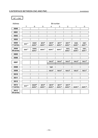
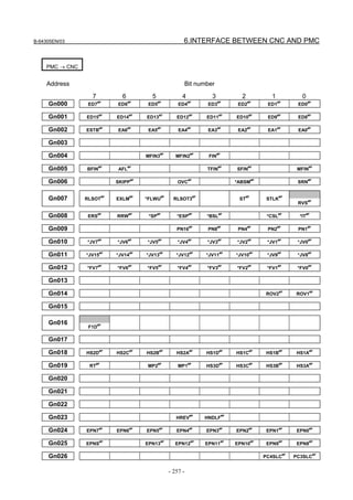
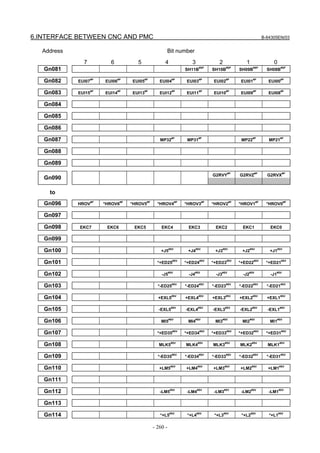
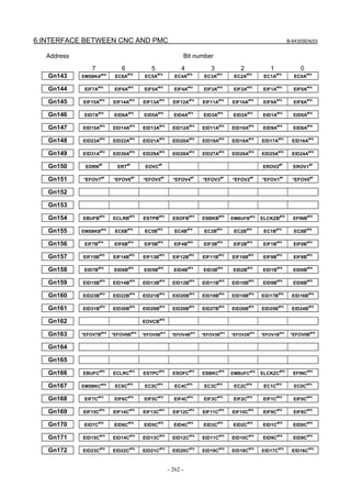
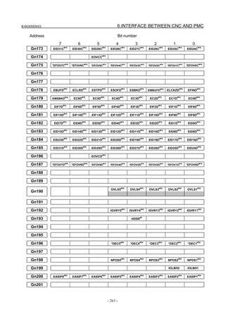
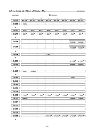
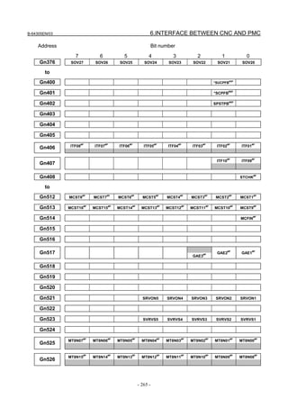
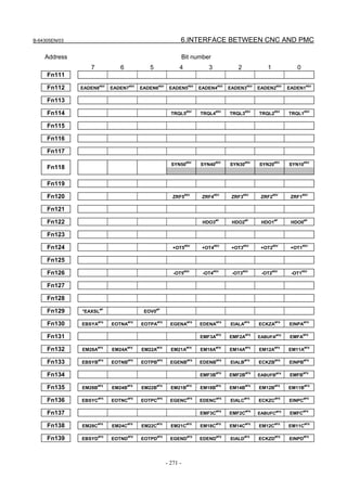
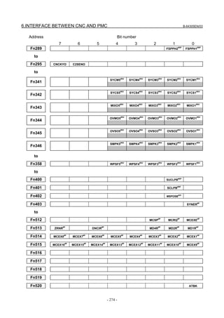
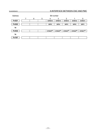
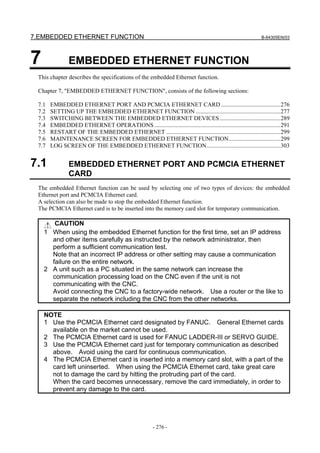
![B-64305EN/03 7.EMBEDDED ETHERNET FUNCTION
- 277 -
Related NC parameters
#7 #6 #5 #4 #3 #2 #1 #0
14880 ETH
[Input type] Setting input
[Data type] Bit
# 0 ETH The embedded Ethernet function (embedded Ethernet port or PCMCIA Ethernet card) is:
0: Used.
1: Not used.
7.2 SETTING UP THE EMBEDDED ETHERNET FUNCTION
This section describes the setting of parameters for the embedded Ethernet function.
7.2.1 Setting of the FOCAS2/Ethernet Function
This subsection describes the settings required to operate the FOCAS2/Ethernet function.
Notes on using the FOCAS2/Ethernet function for the first time
NOTE
1 When running user's original application software created by using the
FOCAS2/Ethernet function, use the embedded Ethernet port.
2 The FOCAS2/Ethernet function allows up to five FOCAS2/Ethernet clients to be
connected to one CNC.
3 Concurrent access by multiple applications or personal computers may overload
the CNC, reducing the communication speed.
7.2.1.1 Operation on the FOCAS2/Ethernet setting screen
On the Ethernet parameter setting screen, set the parameters for operating the FOCAS2/Ethernet function.
Procedure
1 Press the function key .
2 Soft keys [EMBED] and [PCMCIA] appear.
(When there is no soft keys, press the continue key.)
3 To display the Ethernet Setting screen for the embedded Ethernet port or the PCMCIA Ethernet card,
press soft key [EMBED] or [PCMCIA], respectively.
4 Press soft keys [COMMON] and [FOCAS2] and then enter parameters for the items that appear.
NOTE
1 The parameters for the embedded Ethernet port and the parameters for the
PCMCIA Ethernet card are independent of each other.
2 The settings of the FOCAS2/Ethernet function for the PCMCIA Ethernet card are
made when a connection to SERVO GUIDE and FANUC LADDER-III is
established.](https://image.slidesharecdn.com/fanuc0imaintenancemanual-140802043306-phpapp01/85/Fanuc-0i-maintenance-manual-CNC-milling-machine-295-320.jpg)
![7.EMBEDDED ETHERNET FUNCTION B-64305EN/03
- 278 -
COMMON screen (BASIC)
Press soft key [COMMON]. The COMMON screen (BASIC) is displayed.
COMMON screen (BASIC)
Settings items
Item Description
IP ADDRESS Specify the IP address of the embedded Ethernet.
(Example of specification format: "192.168.0.100")
SUBNET MASK Specify a mask address for the IP addresses of the network.
(Example of specification format: "255.255.255.0")
ROUTER IP ADDRESS Specify the IP address of the router.
Specify this item when the network contains a router.
(Example of specification format: "192.168.0.253")
Display items
Item Description
MAC ADDRESS Embedded Ethernet MAC address
AVAILABLE DEVICE Enabled device of the embedded Ethernet.
Either the embedded Ethernet port or the PCMCIA Ethernet card is displayed.](https://image.slidesharecdn.com/fanuc0imaintenancemanual-140802043306-phpapp01/85/Fanuc-0i-maintenance-manual-CNC-milling-machine-296-320.jpg)
![B-64305EN/03 7.EMBEDDED ETHERNET FUNCTION
- 279 -
FOCAS2 screen
Press soft key [FOCAS2]. The FOCAS2 screen is displayed.
FOCAS2 screen
Setting items
Item Description
PORT NUMBER (TCP) Specify a port number to be used with the FOCAS2/Ethernet function. The valid
input range is 5001 to 65535.
PORT NUMBER (UDP) Set this item to 0 when it is used as the FOCAS2/Ethernet function.
TIME INTERVAL Set this item to 0 when it is used as the FOCAS2/Ethernet function.
NOTE
1 When a connection to the CIMPLICITY i CELL is established, set the UDP port
number and time interval above as described in the FANUC CIMPLICITY i CELL
Operator's Manual (B-75074).
2 The unit of the time interval is 10 ms. The allowable range is between 10 and
65535. A time interval less than 100ms cannot be set.
3 Decreasing the time interval setting increases the communication load and can
affect the network performance.
Example) If the interval is set to 100 (100 x 10 ms = 1 second), broadcast data
is sent every 1 second.
Initial setting of the PCMCIA Ethernet card
The PCMCIA Ethernet card is factory-set to the following default values, for ease of connection with
SERVO GUIDE or FANUC LADDER-III.
IP ADDRESS : 192.168.1.1
SUBNET MASK : 255.255.255.0
ROUTER IP ADDRESS : None
PORT NUMBER (TCP) : 8193
PORT NUMBER (UDP) : 0
TIME INTERVAL : 0
If a specified IP address is changed to a blank (space), the specified setting is reset to the default value.
The embedded Ethernet port does not have a default value.](https://image.slidesharecdn.com/fanuc0imaintenancemanual-140802043306-phpapp01/85/Fanuc-0i-maintenance-manual-CNC-milling-machine-297-320.jpg)
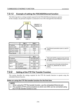
![B-64305EN/03 7.EMBEDDED ETHERNET FUNCTION
- 281 -
7.2.2.1 Operation on the FTP file transfer setting screen
On the Ethernet setting screen, set the parameters for operating the FTP file transfer function.
Procedure
1 Press the function key .
2 Soft keys [EMBED] appear.
(When there is no soft keys, press the continue key.)
3 By pressing the [EMBED] soft key, the Ethernet Setting screen for the embedded Ethernet port is
displayed.
4 Press soft keys [COMMON] and [FTPTRNS] and then enter parameters for the items that appear.
NOTE
The parameters for the embedded Ethernet port and the parameters for the
PCMCIA Ethernet card are independent of each other.
If the [PCMCIA] soft key is pressed, the PCMCIA Ethernet card can be set up.
However, the card setup is carried out for maintenance and is not necessary
usually.
COMMON screen (BASIC)
Press soft key [COMMON]. The COMMON screen (BASIC) is displayed.
COMMON screen (BASIC)
Setting items
Item Description
IP ADDRESS Specify the IP address of the embedded Ethernet.
(Example of specification format: "192.168.0.100")
SUBNET MASK Specify a mask address for the IP addresses of the network.
(Example of specification format: "255.255.255.0")
ROUTER IP ADDRESS Specify the IP address of the router.
Specify this item when the network contains a router.
(Example of specification format: "192.168.0.253")](https://image.slidesharecdn.com/fanuc0imaintenancemanual-140802043306-phpapp01/85/Fanuc-0i-maintenance-manual-CNC-milling-machine-299-320.jpg)
![7.EMBEDDED ETHERNET FUNCTION B-64305EN/03
- 282 -
Display items
Item Description
MAC ADDRESS Embedded Ethernet MAC address
AVAILABLE DEVICE Enabled device of the embedded Ethernet.
Either the embedded Ethernet port or the PCMCIA Ethernet card is displayed.
FTP transfer screen (CONNECT1, CONNECT2, CONNECT3)
1 Press soft key [FTPTRNS]. The FTP transfer screen is displayed.
2 Page keys can be used to make settings for the three host computers for connection
destinations 1 to 3.
FTP transfer screen (1st page)
FTP transfer screen (2nd page)](https://image.slidesharecdn.com/fanuc0imaintenancemanual-140802043306-phpapp01/85/Fanuc-0i-maintenance-manual-CNC-milling-machine-300-320.jpg)
![B-64305EN/03 7.EMBEDDED ETHERNET FUNCTION
- 283 -
Item Description
HOST NAME Specify the IP address of the host computer.
(Example of specification format: "192.168.0.200")
PORT NUMBER Specify a port number to be used with the FTP file transfer function. An FTP session
is used, so that "21" is to be specified usually.
USERNAME Specify a user name to be used for logging in to the host computer with FTP.
(Up to 31 characters can be specified.)
PASSWORD Specify a password for the user name specified above. (Up to 31 characters can be
specified.)
Be sure to set a password.
LOGIN FOLDER Specify a work folder to be used when logging in to the host computer. (Up to 127
characters can be specified.)
If nothing is specified, the home folder specified in the host computer becomes the
log-in folder.
Operation
Select a destination.
1 Pressing the [(OPRT)] soft key causes soft key [HOST] to be displayed. Pressing this soft key
causes soft keys [CONECT 1], [CONECT 2], and [CONECT 3] to be displayed.
2 Depending on the host computer to be connected, press soft key [CONECT 1], [CONECT 2], or
[CONECT 3]. Destination 1, 2, or 3 is highlighted in the screen title field. The computer
corresponding to the highlighted destination is selected as the target computer to be connected.
When destination 1 is selected
7.2.2.2 Related NC parameters
The NC parameters related to the FTP file transfer function are described below.
0020 I/O CHANNEL : Input/output device selection, or interface number for a foreground input device
[Input type] Setting input
[Data type] Byte
[Valid data range] 9 : Select the embedded Ethernet as the input/output device.
#7 #6 #5 #4 #3 #2 #1 #0
13115 SI2 SI1
[Input type] Parameter input
[Data type] Bit
#4 SI1 Soft key input of the characters shown below and switching between the uppercase and
lowercase input modes by a soft key are:
0: Disabled.
1: Enabled.
< > ¥ % $ ! ~ : " '](https://image.slidesharecdn.com/fanuc0imaintenancemanual-140802043306-phpapp01/85/Fanuc-0i-maintenance-manual-CNC-milling-machine-301-320.jpg)
![7.EMBEDDED ETHERNET FUNCTION B-64305EN/03
- 284 -
#5 SI2 Soft key input of the characters shown below and switching between the uppercase and
lowercase input modes by a soft key are:
0: Disabled.
1: Enabled.
( ) ? * & @ _
For embedded Ethernet port
#7 #6 #5 #4 #3 #2 #1 #0
14880 PCH
[Input type] Setting input
[Data type] Bit
#1 PCH When communication based on the FTP file transfer function starts, an FTP server
presence check based on PING is:
0: Made
1: Not made
NOTE
Generally, set this parameter to 0 so that an FTP server presence
check based on PING is performed.
Otherwise, if the server is not present in the network, it takes
several tens of seconds to detect an error.
Some PCs are set not to response to the PING command mainly
for security purposes. To communicate with such a PC, set this
parameter to 1.
14890 Selects the host computer 1 OS.
14891 Selects the host computer 2 OS.
14892 Selects the host computer 3 OS.
[Input type] Parameter input
[Data type] Word
[Valid data range] 0 to 2
0: Windows2000/XP/Vista.
1: UNIX, VMS.
2: Linux.
NOTE
Some FTP server software products do not depend on the OS. So,
even when the above parameters are set, it is sometimes
impossible to display a list of files properly.
7.2.2.3 Example of setting the FTP file transfer function
The following shows a setting example required for the FTP file transfer function to operate.
In this example, one personal computer is connected to two CNCs through the FTP file transfer function.
• On Personal Computer 1, the FTP server function operates.
• On CNC 1 and CNC 2, the FTP client operates as the FTP file transfer function.](https://image.slidesharecdn.com/fanuc0imaintenancemanual-140802043306-phpapp01/85/Fanuc-0i-maintenance-manual-CNC-milling-machine-302-320.jpg)
![B-64305EN/03 7.EMBEDDED ETHERNET FUNCTION
- 285 -
CNC 1 CNC 2
IP address 192.168.0.100 192.168.0.101
Subnet mask 255.255.255.0 255.255.255.0
Router IP address None None
Port number 21 21
IP address 192.168.0.200 192.168.0.200
User name user user
Password user user
Connection
host 1
Login DIR None None
NC parameter No. 20 9 9
PC 1
IP address 192.168.0.200
Subnet mask 255.255.255.0
Default gateway None
User name user
Password user
Login DIR Default
7.2.3 Setting Up the DNS/DHCP Function
The DHCP/DNS function is set up by using the COMMON screen (DETAIL) and NC parameters.
7.2.3.1 Setting up DNS
This subsection describes the procedure for setting up a DNS.
Procedure
1 Enable the DNS function, with reference to "Related NC Parameters," which will be seen later.
2 Set up the DNS server of the host computer.
3 Connect the host computer on which the DNS server is working (hereafter referred to as a DNS
server), reboot the CNC, then press function key .
4 Press soft keys [EMBED] and [COMMON] in that order. The COMMON screen (DETAIL)
appears.
5 Enter the IP address of the DNS server in the corresponding DNS IP address field.
The Ethernet parameter screen is used for
setting.
The parameter screen is used for setting.
"Microsoft TCP/IP property" of the
personal computer (Windows 2000 / XP /
Vista) is used for setting.
"User acount of the personal computer
(Windows 2000 / XP / Vista) is used for
setting.
"Internet service manager" of the
personal computer (Windows 2000 / XP)
is used for setting.
"FTP Publishing Service" (Windows
HUB
CNC 2 PC 1
10BASE-T or
100BASE-TX
CNC 1](https://image.slidesharecdn.com/fanuc0imaintenancemanual-140802043306-phpapp01/85/Fanuc-0i-maintenance-manual-CNC-milling-machine-303-320.jpg)
![7.EMBEDDED ETHERNET FUNCTION B-64305EN/03
- 286 -
COMMON screen (DETAIL)
After pressing soft key [COMMON], press either page key to call a desired COMMON
screen (DETAIL). Specify a DNS IP address.
COMMON screen (DETAIL)
Setting items
Item Description
DNS IP ADDRESS 1, 2 Up to two DNS IP addresses can be specified.
The CNC searches for the DNS server using DNS IP addresses 1 and 2 in that
order.
7.2.3.2 Setting up DHCP
This subsection describes the procedure for setting up a DHCP.
Procedure
1 Enable the DHCP function, with reference to "Related NC Parameters," which will be seen later.
2 Set up the DHCP server of the host computer.
3 Connect the host computer on which the DHCP server is working (hereafter referred to as a DHCP
server), reboot the CNC, then press function key .
4 Press soft keys [EMBED] and [COMMON] in that order. The COMMON screen appears.
5 If the DHCP function of the CNC has been enabled and if the DHCP server is connected
successfully, the DHCP server automatically specifies the following items.
- IP ADDRESS
- SUBNET MASK
- ROUTER IP ADDRESS
- DNS IP ADDRESS
- DOMAIN
If the DHCP server cannot be connected, "DHCP ERROR" is displayed in each field.
6 If the DNS function has also been enabled and if the DHCP server and the DNS server work
together (if the DNS server supports dynamic DNS), enter a host name.](https://image.slidesharecdn.com/fanuc0imaintenancemanual-140802043306-phpapp01/85/Fanuc-0i-maintenance-manual-CNC-milling-machine-304-320.jpg)
![B-64305EN/03 7.EMBEDDED ETHERNET FUNCTION
- 287 -
COMMON screen (basic and detail)
After pressing soft key [COMMON], press either page key to call a desired Ethernet
common setting screen (basic, detail).
If the DHCP server is connected successfully and if the setting data can be obtained, the screen is
displayed as shown below.
When the DHCP server is connected successfully (1st page)
When the DHCP server is connected successfully (2nd page)
If the host name is not specified, the CNC automatically assigns a host name in the
"NC-<MAC-address>" format.
Example of automatically assigned host name
If the DHCP server cannot be connected, the screen is displayed as shown below.](https://image.slidesharecdn.com/fanuc0imaintenancemanual-140802043306-phpapp01/85/Fanuc-0i-maintenance-manual-CNC-milling-machine-305-320.jpg)
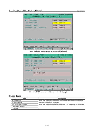
![B-64305EN/03 7.EMBEDDED ETHERNET FUNCTION
- 289 -
Setting items
Item Description
HOST NAME Enter the host name of the CNC.
If a DHCP server and a DNS server work together, the DHCP server notifies the
DNS server of this host name.
If the host name is left blank, a host name is automatically assigned in the
"NC-<MAC-address>" format.
Example of automatically assigned host name:
NC-00E0E4000001
Display items
Item Description
MAC ADDRESS MAC address of embedded Ethernet
7.2.3.3 Related NC parameters
For embedded Ethernet port
#7 #6 #5 #4 #3 #2 #1 #0
14880 DHC DNS D1E
[Input type] Setting input
[Data type] Bit
# 3 D1E When the DHCP function is used:
0: The default parameters for the FOCAS2/Ethernet function are specified.
PORT NUMBER (TCP) 8193
PORT NUMBER (UDP) 0
TIME INTERVAL 0
1: The default parameters for CIMPLICITY i CELL are specified.
PORT NUMBER (TCP) 8193
PORT NUMBER (UDP) 8192
TIME INTERVAL 50
# 5 DNS The DNS function is:
0: Not used.
1: Used.
# 6 DHC The DHCP function is:
0: Not used.
1: Used.
A change in these parameters becomes effective after the power is turned off and on or after the
embedded Ethernet function is restarted.
7.2.4 Backing up and Restoring Communication Parameters
This section describes how to back up the embedded Ethernet communication parameters to a memory
card and to restore them from the memory card.
1. Press the function key .
2. The soft keys [EMBED] and [PCMCIA] appear. (If they do not appear, press the continuous menu
key.)](https://image.slidesharecdn.com/fanuc0imaintenancemanual-140802043306-phpapp01/85/Fanuc-0i-maintenance-manual-CNC-milling-machine-307-320.jpg)
![7.EMBEDDED ETHERNET FUNCTION B-64305EN/03
- 290 -
3. When the soft key [EMBED] or [PCMCIA] is pressed, the Ethernet Setting screen, respectively, for
the embedded Ethernet port or the PCMCIA Ethernet card appears.
4. Once the soft keys [COMMON] and [(OPRT)] are pressed, pressing the soft key [+] displays the soft
keys [BACKUP], [RESTORE], [ALLBACK], and [ALL RES] for backing up or restoring
communication parameters as shown below.
5. Pressing the soft key [BACKUP], [RESTORE], [ALLBACK], or [ALL RES] displays the soft keys
[EXECUTE] and [CANCEL].
6. Once the name of a file to be backed up or restored is entered into a key-in buffer, pressing the soft
key [EXECUTE] starts the respective operation.
"EXECUTING" blinks while backup or restoration is in progress.
BACKUP
The embedded Ethernet communication parameters are saved from the SRAM of the CNC main unit to
the memory card.
If a file name is specified in the key-in buffer, the specified file name is used when the parameters are
saved to the memory card. If no file name is specified, the file name “EMBETHER.MEM” is used.
RESTORE
The embedded Ethernet communication parameters are read from the memory card and saved to the
SRAM of the CNC main unit.
If a file name is specified in the key-in buffer, the specified file name is used when the parameters are
read from the memory card. If no file name is specified, the file name “EMBETHER.MEM” is used.
ALLBACK
All valid embedded Ethernet, Fast Ethernet/Fast Data server, PROFIBUS-DP master/slave, DeviceNet
master/slave, and FL-net communication parameters are saved from the SRAM of the CNC main unit to
the memory card.
If a file name is specified in the key-in buffer, the file name is used when the parameters are saved. If no
file name is specified, the file name “NETWORK.MEM” is used.](https://image.slidesharecdn.com/fanuc0imaintenancemanual-140802043306-phpapp01/85/Fanuc-0i-maintenance-manual-CNC-milling-machine-308-320.jpg)
![B-64305EN/03 7.EMBEDDED ETHERNET FUNCTION
- 291 -
ALL RES
All valid embedded Ethernet, Fast Ethernet/Fast Data server, PROFIBUS-DP master/slave, DeviceNet
master/slave, and FL-net communication parameters are read from the memory card and saved to the
SRAM of the CNC main unit.
However, if a communication function related to a valid communication parameter is disabled in the CNC,
that parameter is not saved to the SRAM.
If a file name is specified in the key-in buffer, the specified file name is used when the parameters are
read from the memory card. If no file name is specified, the file name “NETWORK.MEM” is used.
NOTE
1 Communication parameter backup and restoration are usable only in the MDI
mode and at an emergency stop.
2 Performing communication parameter restoration leads to an alarm condition
that requests to turn off the power.
3 When communication parameters are backed up or restored, the memory card is
always used no matter what the external input/output device number (NC
parameter No. 20) is.
7.3 SWITCHING BETWEEN THE EMBEDDED ETHERNET
DEVICES
There are two types of embedded Ethernet devices: the embedded Ethernet port and PCMCIA Ethernet
card.
Screen operation is required to switch between these two types of devices.
Procedure
1 Press the function key .
2 Soft keys [EMBED] and [PCMCIA] appear.
(When there is no soft keys, press the continue key.)
3 Press soft key [EMBED] or [PCMCIA], press soft key [COMMON], and then press [(OPRT)] to
display soft key [EMB/PCM].
4 Pressing soft key [EMB/PCM] switches between enabled devices.
• If you want to execute the switchover, press soft key [EXECUTE].
• If you do not want to execute the switchover, press soft key [CANCEL].
5 The valid devices are switched each time Step 4 is performed.
NOTE
Information on a switched device is stored in nonvolatile memory.
On the next power-on, the device last selected can be used as is.
7.4 EMBEDDED ETHERNET OPERATIONS
7.4.1 FTP File Transfer Function
The operation of the FTP file transfer function is described below.
Host file list display
A list of the files held on the host computer is displayed.](https://image.slidesharecdn.com/fanuc0imaintenancemanual-140802043306-phpapp01/85/Fanuc-0i-maintenance-manual-CNC-milling-machine-309-320.jpg)
![7.EMBEDDED ETHERNET FUNCTION B-64305EN/03
- 292 -
Procedure
1 Press the function key .
2 Press soft key [DIR+]. The program folder screen appears. (If the soft key does not appear, press the
continuous menu key.)
3 Press soft keys [(OPRT)] and [DEVICE] in that order. The soft keys for selectable devices appear.
4 Pressing soft key [EMB ETH] displays the Embedded Ethernet host file list screen, on which a list
of files in the host computer connected with the embedded Ethernet port is displayed.](https://image.slidesharecdn.com/fanuc0imaintenancemanual-140802043306-phpapp01/85/Fanuc-0i-maintenance-manual-CNC-milling-machine-310-320.jpg)
![B-64305EN/03 7.EMBEDDED ETHERNET FUNCTION
- 293 -
Embedded Ethernet host file list screen (8.4-inch LCD)
Embedded Ethernet host file list screen (10.4-inch LCD)
NOTE
When using the FTP file transfer function, check that the valid device is the
embedded Ethernet port.
The two conditions below determine a connection destination on the host file list
screen:
(1) Check that the valid device is the embedded Ethernet port. To select a
valid device, use soft key [EMB/PCM] on the Ethernet Setting screen.
(2) A host computer can be selected from connection destinations 1, 2, and 3.
A computer to be connected is selected using the operation procedure
described in Subsection 7.2.2.1, "Operation on the FTP file transfer setting
screen" or “HOST CHANGE” explained later.
5 When a list of files is larger than one page, the screen display can be switched using the page keys
.
Display item
DEVICE (AVAILABLE DEVICE)
The currently selected device is displayed.](https://image.slidesharecdn.com/fanuc0imaintenancemanual-140802043306-phpapp01/85/Fanuc-0i-maintenance-manual-CNC-milling-machine-311-320.jpg)
![7.EMBEDDED ETHERNET FUNCTION B-64305EN/03
- 294 -
CON HOST (CONNECT HOST)
Number of the currently connected host of the host computer
REG NUM (REGISTERED PROGRAM)
The number of files in the current folder.
DEVICE
Current device. When the embedded Ethernet host file list is selected, “EMB_ETHER” is displayed.
CURRENT FOLDER
Current work folder in the host computer
FILE LIST
Information of the files and folders in the host computer
Operation list
DEVICE (DEVICE CHANGE)
Enables a device to be selected from the program folder screen. To select the embedded Ethernet host
file list, press soft key [EMB ETH].
DIR +
Switches between the outline and detailed file lists.
F CREAT (CREATE FOLDER)
Create a subfolder in the current work folder in the host computer.
DELETE
Deletes a file or folder in the host computer.
RENAME
Renames a file or folder in the host computer.
HOST (HOST CHANGE)
Changes the connected host computer.
SEARCH
Searches for a file through the current folder in the host computer.
REFRESH
Updates the information displayed on the embedded Ethernet host file list screen.
F INPUT
Transfers a program from the host computer to the CNC memory.
F OUTPUT
Transfers a program from the CNC memory to the host computer.
NOTE
The character strings enclosed in parentheses are those displayed when the
10.4-inch LCD unit is used.](https://image.slidesharecdn.com/fanuc0imaintenancemanual-140802043306-phpapp01/85/Fanuc-0i-maintenance-manual-CNC-milling-machine-312-320.jpg)
![B-64305EN/03 7.EMBEDDED ETHERNET FUNCTION
- 295 -
7.4.1.1 Displaying and operating the file list
DETAIL ON, DETAIL OFF
Displays can be switched between outline and detailed file lists.
Either the outline or detailed file list display is selected each time soft key [DIR+] is pressed.
The outline file list display contains only file names, while the detailed file list display contains file sizes,
creation dates, and other file information as well file names.
NOTE
1 The items displayed in the detailed list depend on the FTP server setting on the
host computer.
2 When files in the detailed file list are operated on, information displayed at the
right edge of the screen is treated as a file name. Therefore, it is likely that files
may not be operated on properly depending on displays or file names. If this is
the case, use the outline file list display.
REFRESH
Update the contents of the file list.
Pressing soft key [REFRESH] causes the file list contents to be updated.
Moving a folder
Move a folder.
1 Select a folder you want to move using cursor keys and .
2 Press MDI key .
CREATE FOLDER
Create a new folder.
1 Move to a folder in which you want to create a new folder.
2 Key in a folder name.
3 Press soft key [F CREAT] ([CREATE FOLDER]).
DELETE
Delete a file or folder.
1 Select a file or folder you want to delete using cursor keys and .
2 Press soft key [DELETE].
• To execute the deletion, press soft key [EXEC].
• To cancel the deletion, soft key [CANCEL].
DELETE (multiple files)
Delete multiple files at a time.
1 Press soft key [SELECT] ([SELECT START]).
2 Select a file or folder you want to delete using cursor keys and .
3 Press soft key [SELECT].
The selected file is highlighted.
Repeat steps 2 and 3 for each file you want to delete.
4 Press soft key [DELETE].](https://image.slidesharecdn.com/fanuc0imaintenancemanual-140802043306-phpapp01/85/Fanuc-0i-maintenance-manual-CNC-milling-machine-313-320.jpg)
![7.EMBEDDED ETHERNET FUNCTION B-64305EN/03
- 296 -
- To execute the deletion, press soft key [EXEC].
- To cancel the deletion, soft key [CANCEL].
NOTE
1 Up to 10 files can be selected at a time.
2 Only files can be specified. If folders are specified, an error is reported when an
attempt is made to delete the folders.
RENAME
Rename a file or folder.
1 Select a file or folder you want to rename using cursor keys and .
2 Enter a new file or folder name.
3 Press soft key [RENAME].
SEARCH
Search for a file or folder through the current work folder. The file or folder found is displayed at the
top of the file list.
1 Key in a file or folder name you want to search for.
2 Press soft key [SEARCH].
HOST CHANGE
Change the connected host computer.
1 Press soft key [HOST] ([HOST CHANGE]).
The connected host number changes from 1 to 2 to 3, then back to 1.
7.4.1.2 Transferring programs
How programs are transferred between the host computer and CNC is explained below.
NOTE
1 Inputting or outputting programs with the embedded Ethernet host requires
setting NC parameter No. 20 with 9.
2 If an error occurs, check its cause on the Ethernet log screen.
Inputting programs
The following procedure can be used to transfer programs from the host computer to the CNC memory.
1 Press soft key [F INPUT].
2 Select a program in the host computer.
In the host computer, place the cursor on the file you want to input and press soft key [F GET], or
key in the file name.
3 Press soft key [F NAME].
4 If you want to rename a program when inputting it, key in the program number and press soft key [O
SET].
5 Press soft key [EXEC].
The following table summarizes what operation occurs when the input file name [F NAME] and input
program number [O SET] are omitted.](https://image.slidesharecdn.com/fanuc0imaintenancemanual-140802043306-phpapp01/85/Fanuc-0i-maintenance-manual-CNC-milling-machine-314-320.jpg)
![B-64305EN/03 7.EMBEDDED ETHERNET FUNCTION
- 297 -
[F NAME] [O SET]
Key input
buffer
Input file name Input program Input program No.
–
Warning message “NO PROGRAM SELECTED” is displayed, and nothing
is input.
Other than
Oxxxx
Warning message “THE WRONG DATA IS USED” is displayed, and
nothing is input.
–
Oxxxx
File name set in the
key input buffer
(NOTE)
All programs in the input
file
Continuous program
numbers starting at one
(xxxx) set in the key
input buffer
-9999
Warning message “NO PROGRAM SELECTED” is displayed, and nothing
is input.
–
O
Same file name as
program No. set by
[O SET] (NOTE)
All programs in the input
file
Continuous program
numbers starting at one
set by [O SET]
–
File name set by [F
NAME]
All programs in a file
specified by [F NAME]
Program No. used when
the program was saved
-9999
Warning message “THE WRONG DATA IS USED” is displayed, and
nothing is input.O
O
No relation
File name set by [F
NAME]
All programs in the file
specified by [F NAME]
Continuous program
numbers starting at one
set by [O SET]
O: Specified
– : Not specified
NOTE
The input file name consists of “O” followed by a 4-digit number.
If program input is executed by specifying program No. 1, for example, a file
whose file name is “O0001” is input.
If this operation is performed for path 2, the file name is suffixed with the file
extension “P-2” (for this example, “O0001.P-2”).
Outputting programs
The following procedure can be used to transfer programs from the CNC memory to the host computer.
1 Press soft key [FOUTPUT].
2 Select a program in the CNC.
Key in the program No. of the program to be output.
3 Press soft key [O SET].
4 If you want to rename a program when outputting it, key in the file name and press soft key [F
NAME].
5 Press soft key [EXEC].
The following table summarizes what operation occurs when the output file name [F NAME] and output
program number [O SET] are omitted.](https://image.slidesharecdn.com/fanuc0imaintenancemanual-140802043306-phpapp01/85/Fanuc-0i-maintenance-manual-CNC-milling-machine-315-320.jpg)
![7.EMBEDDED ETHERNET FUNCTION B-64305EN/03
- 298 -
[F NAME] [O SET]
Key input
buffer
Output file name Output program
–
Currently selected main program
name (NOTE 1 and NOTE 2)
Currently selected main program
(NOTE 1)
Other than
Oxxxx
Warning message “THE WRONG DATA IS USED” is displayed, and
nothing is output.
Oxxxx
Program name set in the key
input buffer (NOTE 2)
Program in the CNC memory set in the
key input butter
–
O-9999
-9999
ALL-PROG.TXT (NOTE 3) All programs in the CNC memory
–
O
Same file name as program No.
set by [O SET] (NOTE 2)
Program in the CNC memory set by [O
SET]
–
Currently selected main program
(NOTE 1)
-9999 All programs in the CNC memoryO
O
No relation
File name set by [F NAME]
Program in the CNC memory set by [O
SET]
O : Specified
– : Not specified
NOTE
1 If a file is undergoing background editing, it is output.
2 The output file name consists of “O” followed by a 4-digit number.
If a program whose program No. is 1 is output, for example, it is output under the
file name “O0001” to the host computer.
If this operation is performed for path 2, the file name is suffixed with the file
extension “P-2” (for this example, “O0001.P-2”).
3 If this operation is performed for path 2, the file name “ALL-PROG.P-2” is used.
7.4.1.3 Inputting special characters
Using bits 4 (SI1) and 5 (SI2) of NC parameter No. 13115 enables special characters and lowercase letters,
which are not available on the MDI keypad, to be entered.
Setting this NC parameter displays soft key [CHA-EXT]([CHARA EXT]). Pressing this soft key
displays the following soft keys:
Pressing soft key [ABC/abc] switches between uppercase and lowercase characters for input. Which
case can be currently input is indicated in the key input field.
Uppercase Lowercase
letter input letter input](https://image.slidesharecdn.com/fanuc0imaintenancemanual-140802043306-phpapp01/85/Fanuc-0i-maintenance-manual-CNC-milling-machine-316-320.jpg)
![B-64305EN/03 7.EMBEDDED ETHERNET FUNCTION
- 299 -
Related NC parameters
#7 #6 #5 #4 #3 #2 #1 #0
13115 SI2 SI1
[Input type] Parameter input
[Data type] Bit
# 4 SI1 Soft key input of the characters shown below and switching between the uppercase and
lowercase input modes by a soft key are:
0: Disabled.
1: Enabled.
< > ¥ % $ ! ~ : " '
# 5 SI2 Soft key input of the characters shown below and switching between the uppercase and
lowercase input modes by a soft key are:
0: Disabled.
1: Enabled.
( ) ? * & @ _
7.5 RESTART OF THE EMBEDDED ETHERNET
Communication using the embedded Ethernet can be restarted.
Procedure
1 Press the function key .
2 Soft keys [EMBED] and [PCMCIA] appear.
(When there is no soft keys, press the continue key.)
3 Press soft key [EMBED] or [PCMCIA], press soft key [COMMON], and then press [(OPRT)] to
display soft key [RESTART].
4 Pressing soft key [RESTART] resets embedded Ethernet communication and then restarts it.
NOTE
1 Pressing soft key [RESTART] forcibly interrupts communication even when it is
in progress.
2 This function makes a restart by software. An actual restart may be impossible
under some conditions.
7.6 MAINTENANCE SCREEN FOR EMBEDDED ETHERNET
FUNCTION
With the embedded Ethernet function, a dedicated maintenance screen is available.
The maintenance screen enables operations to be checked when the embedded Ethernet function operates
abnormally.
Displaying and operating the PING screen
Procedure
1 Press the function key .
2 Soft keys [EMBED] and [PCMCIA] appear.](https://image.slidesharecdn.com/fanuc0imaintenancemanual-140802043306-phpapp01/85/Fanuc-0i-maintenance-manual-CNC-milling-machine-317-320.jpg)
![7.EMBEDDED ETHERNET FUNCTION B-64305EN/03
- 300 -
(When there is no soft keys, press the continue key.)
3 By pressing the [EMBED] soft key, the Ethernet Setting screen for the embedded Ethernet is
displayed.
By pressing the [PCMCIA] soft key, the Ethernet Setting screen for the PCMCIA Ethernet card can
be set.
4 Press soft key [PING] and then press [(OPRT)].
5 To send the PING command to connection destination 1 for FTP file transfer, press soft key
[P.FTP1]. Similarly, to send the PING command to connection destination 2 or 3, press [P.FTP2] or
[P.FTP3], respectively.
PING connection status screen
6 To send the PING command to the desired destination, enter the address of the destination on the
PING setting screen. (Page keys are used for switching.)
PING connection setting screen](https://image.slidesharecdn.com/fanuc0imaintenancemanual-140802043306-phpapp01/85/Fanuc-0i-maintenance-manual-CNC-milling-machine-318-320.jpg)
![B-64305EN/03 7.EMBEDDED ETHERNET FUNCTION
- 301 -
7 After entering the address and the repeat count, press the soft key [P.EXEC]. The specified number
of PING commands are sent to the specified destination.
8 To cancel the PING command currently being sent, press soft key [P.CAN].
Displaying Communication status screen
Procedure
1 Press the function key .
2 Soft keys [EMBED] and [PCMCIA] appear.
(When there is no soft keys, press the continue key.)
3 By pressing the [EMBED] soft key, the Ethernet Setting screen for the embedded Ethernet is
displayed.
By pressing the [PCMCIA] soft key, the Ethernet Setting screen for the PCMCIA Ethernet card can
be set.
4 To display the communication status of the embedded Ethernet, press soft key [COM STS].
Page keys can be used to switch between the sending state and the receiving state.
Communication status screen (1st page)](https://image.slidesharecdn.com/fanuc0imaintenancemanual-140802043306-phpapp01/85/Fanuc-0i-maintenance-manual-CNC-milling-machine-319-320.jpg)
![7.EMBEDDED ETHERNET FUNCTION B-64305EN/03
- 302 -
Communication status screen (2nd page)
Display items
Display item Explanation
BAUDRATE Indicates the communication speed and communication mode.
Communication speed: 100 or 10 Mbps
Communication mode: Full or half duplex
--------: Not connected to HUB
SEND PACKET Indicates the number of packets sent.
COLLISION
CARRIER SENSE LOST
DELAYOVER
UNDERRUN
SEND PARITY ERROR
Indicate the number of errors detected during packet transmission.
RECEIVE PACKET Indicates the number of packets received.
ALIGNMENT ERROR
CRC ERROR
OVERRUN ERROR
FRAME LENGTH ERROR
RECV PARITY ERROR
Indicate the number of errors detected during packet reception.
Displaying Task status screen
Procedure
1 Press the function key .
2 Soft keys [EMBED] and [PCMCIA] appear.
(When there is no soft keys, press the continue key.)
3 To display the Ethernet Setting screen for the embedded Ethernet port or the PCMCIA Ethernet card,
press soft key [EMBED] or [PCMCIA], respectively.
4 Pressing soft key [TSK STS] causes the task status of the embedded Ethernet function to be
displayed.](https://image.slidesharecdn.com/fanuc0imaintenancemanual-140802043306-phpapp01/85/Fanuc-0i-maintenance-manual-CNC-milling-machine-320-320.jpg)
![7.EMBEDDED ETHERNET FUNCTION B-64305EN/03
- 304 -
Displaying the log screen
Procedure
1 Press the function key .
2 To display the log screen for the embedded Ethernet port or PCMCIA Ethernet card, press soft key
[EMB LOG] or [PCM LOG], respectively. (When there is no soft keys, press the continue key.)
LOG screen
The newest error log appears at the top of the screen. The date and time when an error occurred are
displayed at the right end of the line. The format of date and time data is “MMM.DD hh:mm:ss” where
MMM represents a month, DD represents a day, hh represents hours, mm represents minutes, and ss
represents seconds.
The date and time of the upper item shown above is January 28, 12:28:17.
To clear the log, press soft keys [(OPRT)] and [CLEAR] in that order.
The log for each function can be displayed by using soft keys on the embedded Ethernet log screen.
(1) Soft key [ALL]
Displays all log related to the embedded Ethernet.
(2) Soft key [COMMON]
Displays the log related to the parameter settings of the embedded Ethernet function and the basic
communication function.
(3) Soft key [FOCAS2]
Displays the log related to the FOCAS2/Ethernet function.
(4) Soft key [FTPTRNS]
Displays the log related to FTP file transfer.](https://image.slidesharecdn.com/fanuc0imaintenancemanual-140802043306-phpapp01/85/Fanuc-0i-maintenance-manual-CNC-milling-machine-322-320.jpg)

![B-64305EN/03 8.DIGITAL SERVO
- 307 -
8 DIGITAL SERVO
This chapter describes servo tuning screen required for maintenance of digital servo and adjustment of
reference position.
8.1 INITIAL SETTING SERVO PARAMETERS.................................................................................307
8.2 FSSB DISPLAY AND SETTING SCREEN....................................................................................316
8.3 SERVO TUNING SCREEN.............................................................................................................322
8.4 ADJUSTING REFERENCE POSITION (DOG METHOD)............................................................328
8.5 DOGLESS REFERENCE POSITION SETTING ............................................................................330
8.6 αi SERVO WARNING INTERFACE..............................................................................................332
8.7 αi SERVO INFORMATION SCREEN............................................................................................333
8.1 INITIAL SETTING SERVO PARAMETERS
This section describes how to set initial servo parameters, which is used for field adjustment of machine
tool.
1. Turn on power at the emergency stop condition.
2. Set parameters for displaying the servo setting screen and servo tuning screen.
#7 #6 #5 #4 #3 #2 #1 #0
3111 SVS
[Input type] Setting input
[Data type] Bit path
#0 SVS Servo setting screen or servo tuning screen is:
0: Not displayed.
1: Displayed.
3. Set the parameter for the display format of the servo setting screen as required.
#7 #6 #5 #4 #3 #2 #1 #0
13117 SVO
[Input type] Parameter input
[Data type] Bit
#2 SVO On the servo setting screen,
0: Two screens, machine constant input screen and parameter input screen, are
displayed.
1: Only the parameter input screen is displayed.
Remark
When bit 2 (SVO) of parameter No. 13117 is set to 0, after displaying the servo setting screen,
press soft key [(OPRT)], continuous menu key [+], and soft key [SWITCH] to display the
parameter input screen.
When bit 2 (SVO) of parameter No. 13117 is set to 1, the parameter input screen is displayed
directly by performing the procedure for displaying the servo setting screen.
This section describes operations using the parameter input screen of the servo setting screen.
Therefore, setting this parameter makes operations described in this section easy.](https://image.slidesharecdn.com/fanuc0imaintenancemanual-140802043306-phpapp01/85/Fanuc-0i-maintenance-manual-CNC-milling-machine-325-320.jpg)
![8.DIGITAL SERVO B-64305EN/03
- 308 -
4. Turn off the power once then turn it on again.
5. Display the servo parameter setting screen by the following operation: Function key →
→ [SV.SET].
When bit 2 (SVO) of parameter No. 13117 described above is set to 0, also press soft key [(OPRT)],
continuous menu key [+], and soft key [SWITCH] to display the parameter input screen.
6. Input data required for initial setting using the cursor and page key.
(1) Initial set bit
#7 #6 #5 #4 #3 #2 #1 #0
2000 DGPRM PLC01
#0 PLC01 0: Values of parameters Nos. 2023 and 2024 are used as they are:
1 : Values of parameters Nos. 2023 and 2024 are multiplied by 10.
#1 DGPRM 0: Initial setting of digital servo parameter is done.
1: Initial setting of digital servo parameter is not done.
(2) Motor ID No.
Select the motor type No. of a servo motor to be used from the following table according to a motor
model and specification (four digits in the middle part of “A06B-xxxx-Bxxx).
Table 8.1 (a) αiS series servo motor
Motor model Motor specification Motor type No.
αiS 2 /5000 0212 262
αiS 2 /6000 0218 284
αiS 4 /5000 0215 265
αiS 8 /4000 0235 285
αiS 8 /6000 0232 290
αiS 12 /4000 0238 288
αiS 22 /4000 0265 315
αiS 22 /6000 0262 452
αiS 30 /4000 0268 318
Parameter No.2000
Parameter No.2020
Parameter No.2001
Parameter No.1820
Parameter No.2084
Parameter No.2085
Parameter No.2022
Parameter No.2023
Parameter No.2024
Parameter No.1821](https://image.slidesharecdn.com/fanuc0imaintenancemanual-140802043306-phpapp01/85/Fanuc-0i-maintenance-manual-CNC-milling-machine-326-320.jpg)
![B-64305EN/03 8.DIGITAL SERVO
- 311 -
Table 8.1 (h) αCi series servo motor
Motor model Motor specification Motor type No.
αC4/3000i 0221 271
αC8/2000i 0226 276
αC12/2000i 0241 291
αC22/2000i 0246 296
αC30/1500i 0251 301
(3) Arbitrary AMR function
#7 #6 #5 #4 #3 #2 #1 #0
2001 AMR7 AMR6 AMR5 AMR4 AMR3 AMR2 AMR1 AMR0
* Set "00000000".
(4) CMR
1820 Command multiply ratio
1) When CMR is 1/2 to 1/27
1
Set value=
CMR
+ 100
2) When CMR is 1 to 48
Set value=2×CMR
(5) Turn off the power then back on.
(6) N/M of flexible feed gear (F⋅FG)
2084 n for flexible feed gear
2085 m for flexible feed gear
Setting for the αi Pulsecoder in the semi-closed mode
F⋅FG numerator (≤ 32767)
Necessary position feedback
pulses per motor revolution
F⋅FG denominator (≤ 32767) = 1,000,000 (Note 2)
(Note 1)
(as irreducible fraction)
NOTE
1 For both F⋅FG number and denominator, the maximum setting value (after
reduced) is 32767.
2 αi Pulsecoders assume one million pulses per motor revolution, irrespective of
resolution, for the flexible feed gear setting.
3 If the calculation of the number of pulses required per motor revolution involves
p, such as when a rack and pinion are used, assume π to be approximately
355/113.
[Example]
If the machine is set to detection in 1,000 degree units with a gear reduction ratio of 10:1 for
the rotation axis, the table rotates by 360/10 degrees each time the motor makes one turn.
1000 position pulses are necessary for the table to rotate through one degree.](https://image.slidesharecdn.com/fanuc0imaintenancemanual-140802043306-phpapp01/85/Fanuc-0i-maintenance-manual-CNC-milling-machine-329-320.jpg)
![8.DIGITAL SERVO B-64305EN/03
- 312 -
The number of position pulses necessary for the motor to make one turn is:
360/10 × 1000 = 36000 with reference counter =36000
F⋅FG numerator 36000 36
F⋅FG denominator
=
1,000,000
=
1000
Other F⋅FG (numerator/denominator) setting examples (reduction ratio = 1:1)
Ball screw leadDetection
unit 6mm 8mm 10mm 12mm 16mm 20mm
1μm 6 /1000 8/1000 10/1000 12/1000 16/1000 20/1000
0.5μm 12 /1000 16/1000 20/1000 24/1000 32/1000 40/1000
0.1μm 60 /1000 80/1000 100/1000 120/1000 160/1000 200/1000
Setting for use of a separate detector (full-closed)
F⋅FG numerator (≤ 32767)
Number of position pulses corresponding to a
predetermined amount of travel
F⋅FG denominator (≤ 32767) = Number of position pulses corresponding to a
predetermined amount of travel from a
separate detector
(as irreducible
fraction)
[Example]
To detect a distance of 1 μm using a 0.5 μm scale, set the following:
Numerator of F⋅FG L/1 1
Denominator of F⋅FG
=
L/0.5
=
2
Other F⋅FG (numerator/denominator) setting examples
Resolution of scale
Detection unit
1μm 0.5μm 0.1μm 0.05μm
1μm 1/1 1/2 1/10 1/20
0.5μm - 1/1 1/5 1/10
0.1μm - - 1/1 1/2
(7) Direction of travel
2022 Rotational direction of motor
111 : Normal (clockwise) / -111 : Reverse (counterclockwise)
(8) Number of speed pulses, Number of position pulses
Closed loopSemi-closed
loop Parallel type Serial linear scale Serial rotary scale
Command unit (μm) 1/0.1 1/0.1 1/0.1 1/0.1
Initial bit setting Bit 0=0 Bit 0=0 Bit 0=0 Bit 0=0
Number of speed pulses 8192 8192 8192 8192
Number of position pulses 12500(*1) (*2 - Example 1) (*2 - Example 1) (*2 - Example 2)
Set 8192 as the number of speed pulses.](https://image.slidesharecdn.com/fanuc0imaintenancemanual-140802043306-phpapp01/85/Fanuc-0i-maintenance-manual-CNC-milling-machine-330-320.jpg)
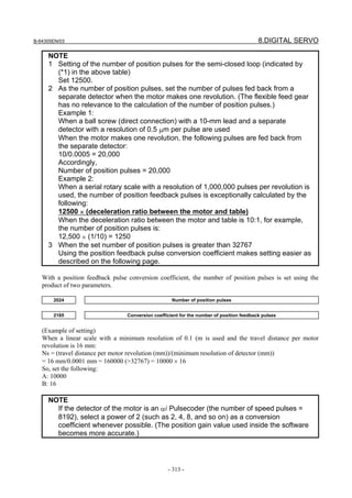
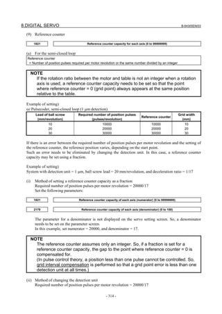
![B-64305EN/03 8.DIGITAL SERVO
- 315 -
The values of all of the following parameters are multiplied by 17 to change the detection unit to
1/17 μm:
Parameter to be changed
FFG × 17
CMR × 17
Reference counter × 17
Effective area × 17
Positional deviation limit value during movement × 17
Positional deviation limit value during a stop × 17
Backlash amount × 17
Can be changed on the servo setting screen.
Can be changed on the servo setting screen.
Can be changed on the servo setting screen.
No.1826, No.1827
No.1828
No.1829
No.1851, No.1852
As the detection unit is changed from 1 μm to 1/17 μm, the values of all parameters to be set using
the detection unit must be multiplied by 17.
CAUTION
In addition to the parameters listed above, there are parameters to be set using
the detection unit.
For detailed descriptions, refer to [Unit of data] in each parameter description in
the Parameter Manual (B-64310EN).
This change eliminates an error between the required number of position pulses per motor revolution
and the reference counter.
Required number of position pulses per motor revolution = 20000
Reference counter = 20000
(b) For the closed loop
Reference counter = Z phase (reference position) interval/detection unit or the same number divided by an integer
If the reference counter does not assume an integer, see the example of semi-closed loop.
NOTE
If the rotation ratio between the separate detector and table is not an integer
when a rotation axis is used, a reference counter capacity needs to be set so
that the point where reference counter = 0 (grid point) always appears at the
same position relative to the table.
Example of setting)
Example 1)
When Z phase interval = 50 mm and detection unit = 1 μm
Reference counter = 50,000/1 = 50,000
Example 2)
When detection unit = 0.001° with a rotation axis
Reference counter = 360/0.001 = 360,000
Example 3)
When there is only one Z phase as in the case of a linear scale
Set a simple number such as 10000 and 50000 for the reference counter.
7. Turn off the power then back on.](https://image.slidesharecdn.com/fanuc0imaintenancemanual-140802043306-phpapp01/85/Fanuc-0i-maintenance-manual-CNC-milling-machine-333-320.jpg)
![8.DIGITAL SERVO B-64305EN/03
- 316 -
8.2 FSSB DISPLAY AND SETTING SCREEN
Connecting the CNC control unit to servo amplifiers via a high-speed serial bus (FANUC Serial Servo
Bus, or FSSB), which uses only one fiber optics cable, can significantly reduce the amount of cabling in
machine tool electrical sections.
Using the FSSB setting screen to specify axis-to-amp relationships enables axis settings to be calculated
automatically; that is, if bit 0 (DFS) of parameter No. 14476 = 0, parameters Nos. 1023, 1905, 1936, 1937,
14340 to 14349, and 14376 to 14391 are set automatically, and if bit 0 (DFS) of parameter No. 14476 = 1,
parameters Nos. 1023, 1905, 1910 to 1919, 1936, and 1937 are set automatically.
Display
The FSSB setting screen displays FSSB-based amplifier and axis information. This information can also
be specified by the operator.
1 Press function key .
2 To display [FSSB], press continuous menu key several times.
3 Pressing soft key [FSSB] causes the AMP SET screen (or the previously selected FSSB setting
screen) to appear, with the following soft keys displayed.
The FSSB setting screens include: AMP SET, AXIS SET, and AMP MAINTENANCE.
Pressing soft key [AMP] causes the AMP SET screen to appear.
Pressing soft key [AXIS] causes the AXIS SET screen to appear.
Pressing soft key [MAINTE] causes the AMP MAINTENANCE screen to appear.
<1> Amplifier setting screen
The amplifier setting screen consists of two sections: the first section displays information about the
slave, while the second section displays information about the separate detector interface units.
Page keys and can be used to switch between the sections.](https://image.slidesharecdn.com/fanuc0imaintenancemanual-140802043306-phpapp01/85/Fanuc-0i-maintenance-manual-CNC-milling-machine-334-320.jpg)
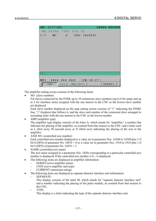
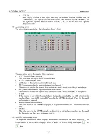
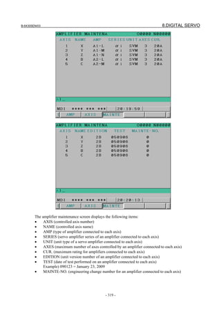
![8.DIGITAL SERVO B-64305EN/03
- 320 -
Setting
On an FSSB setting screen (other than the amplifier maintenance screen), pressing soft key [(OPRT)]
displays the following operation selection soft keys:
To enter data, place the machine in MDI mode or the emergency stop state, position the cursor to the
point where a desired item is to be input, then enter the desired data and press soft key [INPUT] (or the
key on the MDI panel).
When soft key [SETING] is pressed after data is entered, a warning message is displayed if the entered
data is incorrect. When the entered data is correct, it is set in parameters Nos. 1023, 1905, 1936, 1937,
14340 to 14349, and 14376 to 14391 if bit 0 (DFS) of parameter No. 14476 = 0 or parameter Nos. 1023,
1905, 1910 to 1919, 1936, and 1937 if bit 0 (DFS) of parameter No. 14476 = 1.
To restore the previous value of a parameter if, for example, an entered value is incorrect, press soft key
[CANCEL].
When the power is turned on, values are read from the parameters and displayed on the screen.
CAUTION
1 For the parameters to be specified on the FSSB setting screen, do not attempt to
enter values on the parameter screen using the MDI or a G10 command. Use
only the FSSB screen to enter values for these parameters.
2 If pressing soft key [SETING] results in a warning being issued, re-enter the data
or press soft key [CANCEL] to reset the warning. Pressing the reset key cannot
reset the warning.
<1> Amplifier setting screen
The amplifier setting screen displays the following items:
• NO. (controlled axis number)
For this item, enter a value of between 1 and the maximum number of controlled axes. If a
number that falls outside this range is entered, the warning message "INVALID FORMAT"
appears. If the entered controlled axis number is duplicate or 0, the warning message
"SPECIFIED DATA IS OUT OF RANGE" appears when soft key [SETING] is pressed to
assert the entered value. In this case, no value can be entered for the parameter.](https://image.slidesharecdn.com/fanuc0imaintenancemanual-140802043306-phpapp01/85/Fanuc-0i-maintenance-manual-CNC-milling-machine-338-320.jpg)
![B-64305EN/03 8.DIGITAL SERVO
- 321 -
<2> Axis setting screen
On the axis setting screen, the following items can be specified:
• M1 (connector number for separate detector interface unit 1)
M2 (connector number for separate detector interface unit 2)
For an axis on which to use each separate detector interface unit, enter a connector number with
a number 1 to 8 (maximum number of connectors on a separate detector interface unit).
When a separate detector interface unit is not connected and a number that falls outside the
valid range is entered, the warning message “ILLEGAL DATA” is displayed. When a
separate detector interface unit is connected and a number that falls outside the valid range is
entered, the warning message “DATA IS OUT OF RANGE” is displayed.
• 1-DSP
If the number of servo HRV3 controlled axes that can be controlled by one DSP is limited, set
the number of axes controllable by one DSP.
Number of servo HRV3 controlled axes Setting: 3
The same value is set for axes other than Cs contour controlled axes.
If a value other than 0, 1, and 3 is input, the warning "INVALID FORMAT" is output.
• Cs (Cs contour controlled axis)
Enter spindle number (1 to 2) for the Cs contour controlled axis. If a number other than 0 to 2 is
entered, the warning message “DATA IS OUT OF RANGE” is displayed.
• TNDM (or M/S if EGB (T series) is enabled)
Enter odd and even numbers for axes for tandem control or EGB (T series). These numbers
must be consecutive and within a range between 1 and the number of controlled axes. If a
number that falls outside the valid range is entered, the warning message “DATA IS OUT OF
RANGE” is displayed.
When soft key [SETING] is pressed on the axis setting screen after data entry, the warning message
“DATA IS OUT OF RANGE” is displayed if any of the following conditions is satisfied.
• The setting disables the connection of controlled axes with amplifiers and separate detector
interface units.
• A value other than 0 is specified for both M1 and M2 for an axis.
• A value other than 0 is specified for both Cs and TNDM for an axis.
• 1-DSP is 1 and TNDM is not 0 for an axis.
• 1-DSP is 3 and TNDM is specified for a multiple of four for an axis.
• A duplicate value is specified for M1.
• A duplicate value is specified for M2.
• A duplicate value is specified for Cs.](https://image.slidesharecdn.com/fanuc0imaintenancemanual-140802043306-phpapp01/85/Fanuc-0i-maintenance-manual-CNC-milling-machine-339-320.jpg)
![8.DIGITAL SERVO B-64305EN/03
- 322 -
• A duplicate value is specified for TNDM.
• An invalid master/slave axis pair is specified for TNDM.
8.3 SERVO TUNING SCREEN
8.3.1 Parameter Setting
Set a parameter to display the servo tuning screen.
#7 #6 #5 #4 #3 #2 #1 #0
3111 SVS
[Input type] Setting input
[Data type] Bit path
#0 SVS Servo setting screen or servo tuning screen is:
0: Not displayed.
1: Displayed.
8.3.2 Displaying Servo Tuning Screen
1 Press function key key, continuous menu key , and soft key [SV.SET] in this order.
2 Press soft key [SV.TUN] to select the servo tuning screen.
<1>
<2>
<3>
<4>
<5>
<6>
<7>
<8>
<9>
<10>
<11>
<12>
<13>
<14>
<15>
<16>
<17>
<18>](https://image.slidesharecdn.com/fanuc0imaintenancemanual-140802043306-phpapp01/85/Fanuc-0i-maintenance-manual-CNC-milling-machine-340-320.jpg)
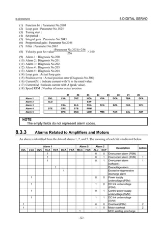
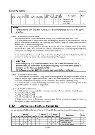
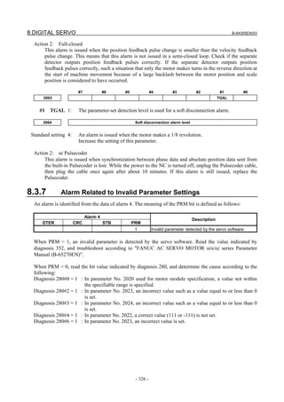
![B-64305EN/03 8.DIGITAL SERVO
- 327 -
8.3.8 Others
An alarm is identified from the data of alarm 5. The meaning of each bit is indicated below.
Alarm 5
OFS MCC LDM PMS FAN DAL ABF
Description Action
1 Feedback mismatch alarm 1
1 Semi-closed/closed loop excessive error alarm 2
1 Current offset error alarm 3
Action 1:
This alarm is issued when the move direction of the position detector becomes opposite to the move
direction of the speed detector. Check the rotation direction of the separate detector. If the rotation
direction of the separate detector is opposite to the rotation direction of the motor, take the following
action:
For the A/B phase detector:
Exchange the connections of A and A with each other.
For the serial detector:
Reverse the following signal direction setting for the separate detector.
Even with the A/B phase detector, the signal direction can be reversed by setting the parameter
below. This method cannot be used when absolute position communication is required.
#7 #6 #5 #4 #3 #2 #1 #0
2018 RVRSE
#0 RVRSE Whether to reverse the signal direction of the separate detector can be set.
0: Does not reverse the signal direction of the separate detector.
1: Reverses the signal direction of the separate detector.
If there is a large distortion between the motor and separate detector, it is likely that the signal direction
may be reversed when the motor accelerates or decelerates steeply. In such a case, change the detection
level.
#7 #6 #5 #4 #3 #2 #1 #0
2018 RNLV
#1 RNLV The detection level of a feedback mismatch alarm can be changed.
0: Detected at 600 mm-1
or more
1: Detected at 1000 min-1
or more
Action 2:
This alarm is issued when the difference between the motor position and separate detector position
exceeds the semi-closed/closed loop excessive error level. Check if the dual position feedback
conversion coefficient is set correctly. If the dual position feedback conversion coefficient is set
correctly, increase the alarm level. If this alarm is still issued after changing the level, check the
connection direction of the scale.
2078 Dual position feedback conversion coefficient (numerator)
2079 Dual position feedback conversion coefficient (denominator)
2118 Dual position feedback semi-closed/full-closed loop error level
[Setting] Detection unit. When 0 is set, no detection operation is performed.](https://image.slidesharecdn.com/fanuc0imaintenancemanual-140802043306-phpapp01/85/Fanuc-0i-maintenance-manual-CNC-milling-machine-345-320.jpg)
![8.DIGITAL SERVO B-64305EN/03
- 328 -
Action 3:
The current offset value (equivalent to the current value during an emergency stop) of the current
detector becomes abnormally high. If this alarm is still issued after the power is turned off then back
on, the current detector is considered to be faulty. When using the αi series, replace the amplifier.
8.4 ADJUSTING REFERENCE POSITION (DOG METHOD)
Overview
+
Speed
Rapid traverse
(Parameter No. 1420)
FL rate
(Parameter No. 1425)
Rapid traverse acc./dec. time constant (Parameter No. 1620)
Time
*DECn
PCZ
Grid
Grid shift amount
(Parameter No. 1850)
Reference counter capacity
(Parameter No. 1821)
10mm/rev
10000P
Error
counter
Proportion
gain
Speed
loop
MCMR
Counter capacity
10000P
-
Command
×4 (Serial)
Reference
counter
F⋅FG PC
GRID
10000P/rev (Flexible feed gear)
Parameter
There are the following related parameters.
#7 #6 #5 #4 #3 #2 #1 #0
1005 DLZx
[Input type] Parameter input
[Data type] Bit axis
# 1 DLZx Function for setting the reference position without dogs
0: Disabled
1: Enabled](https://image.slidesharecdn.com/fanuc0imaintenancemanual-140802043306-phpapp01/85/Fanuc-0i-maintenance-manual-CNC-milling-machine-346-320.jpg)
![B-64305EN/03 8.DIGITAL SERVO
- 329 -
1821 Reference counter size for each axis
NOTE
When this parameter is set, the power must be turned off before
operation is continued.
[Input type] Parameter input
[Data type] 2-word axis
[Unit of data] Detection unit
[Valid data range] 0 to 999999999
Set a reference counter size.
As a reference counter size, specify a grid interval for reference position return based on
the grid method.
When a value less than 0 is set, the specification of 10000 is assumed.
When a linear scale with absolute address reference marks is used, set the interval of
mark 1.
1850 Grid shift and reference position shift for each axis
NOTE
When this parameter is set, the power must be turned off before
operation is continued.
[Input type] Parameter input
[Data type] 2-word axis
[Unit of data] Detection unit
[Valid data range] -99999999 to 99999999
To shift the reference position, the grid can be shifted by the amount set in this parameter.
Up to the maximum value counted by the reference counter can be specified as the grid
shift.
In case of parameter SFDx(No.1008#4) is 0: Grid shift
In case of parameter SFDx(No.1008#4) is 1: Reference point shift
NOTE
For setting the reference position without dogs, only the grid shift
function can be used.
(The reference position shift function cannot be used.)
#7 #6 #5 #4 #3 #2 #1 #0
1815 APCx APZx OPTx
[Input type] Parameter input
[Data type] Bit axis
NOTE
When at least one of these parameters is set, the power must be
turned off before operation is continued.
# 1 OPTx Position detector
0: A separate Pulsecoder is not used.
1: A separate Pulsecoder is used.](https://image.slidesharecdn.com/fanuc0imaintenancemanual-140802043306-phpapp01/85/Fanuc-0i-maintenance-manual-CNC-milling-machine-347-320.jpg)
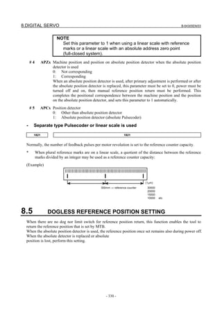
![B-64305EN/03 8.DIGITAL SERVO
- 331 -
Overview
Time
Speed
Reference position return
FL rate (PRM 1425)
JOG
ZRN
+Jn
GRID
ZP n
. . . . . . . . . . . . . .. . . . . . . . . . . . . . .
Operation
<1> Jog-feed the axis for which you want to set a reference position in the reference position return
direction and stop it a little short of the reference position.
<2> Select the manual reference position return mode and set the feed axis and direction select signal (+
or – direction) for the axis for setting the reference position to 1.
<3> The tool is positioned at the nearest grid (electric grid based on the one-rotation signal of the
position detector) in the reference position return direction specified in bit 5 (ZMIx) of parameter No.
1006 from the current position. This position is set as the reference position.
<4> After the in-position status is confirmed, the reference position return completion signal (ZPn) and
reference position establishment signal (ZRFn) are set to 1.
* Once a reference position is set up, simply providing the axis direction signal manually with the
ZRN signal set to “1” causes the axis to return to the reference position.
Parameter
There are the following related parameters.
#7 #6 #5 #4 #3 #2 #1 #0
1005 DLZx
[Input type] Parameter input
[Data type] Bit axis
#1 DLZx Function for setting the reference position without dogs
0: Disabled
1: Enabled
#7 #6 #5 #4 #3 #2 #1 #0
1006 ZMIx
[Input type] Parameter input
[Data type] Bit axis](https://image.slidesharecdn.com/fanuc0imaintenancemanual-140802043306-phpapp01/85/Fanuc-0i-maintenance-manual-CNC-milling-machine-349-320.jpg)
![8.DIGITAL SERVO B-64305EN/03
- 332 -
NOTE
When this parameter is set, the power must be turned off before
operation is continued.
#5 ZMIx The direction of manual reference position return is:
0: + direction
1: - direction
8.6 αi SERVO WARNING INTERFACE
Overview
The αi servo system can report the warning status before one of the following target alarms occurs.
When the warning status is entered, a report to the PMC is issued.
For example, this signal can be used by the machine for retracting tools from the time a warning occurs
by the time a servo alarm occurs.
Signal
Servo warning detail signals SVWRN1 to 4 <F093.4 to F093.7>
[Classification] Output signal
[Function] Reports the warning signal corresponding to the state of the servo amplifier.
[Output condition] The following table shows the warning statuses of the servo amplifier and their
corresponding warning signals.
Warning status signals
Corresponding alarm messages SVWRN4
(F093.7)
SVWRN3
(F093.6)
SVWRN2
(F093.5)
SVWRN1
(F093.4)
Time from when a warning
state signal is issued to until
an alarm occurs
444 n AXIS: INV. COOLING FAN
FAILURE
1 0 0 0
Until overheat occurs
(inconstant)
601 n AXIS: INV. RADIATOR FAN
FAILURE
1 0 0 1
Until overheat occurs
(inconstant)
443 n AXIS: CNV. COOLING FAN
FAILURE
1 1 0 0
Until overheat occurs
(inconstant)
606 n AXIS: CNV. RADIATOR
FAN FAILURE
1 1 0 1
Until overheat occurs
(inconstant)
431 n AXIS: CNV. OVERLOAD 1 1 1 0 One minute
607 n AXIS: CNV. SINGLE
PHASE FAILURE
1 1 1 1
PSMR: Five seconds,
PSM: One minute
A timing chart for handling a warning is shown below.
Occurrence and stop of the alarm corresponding to a warning
Occurrence of a warning
Servo amplifier
SVWRN1-4
(Warning)
PMC Perform deceleration stop or block stop
during this time period with the PMC to
stop the machine without damage. The
time period varies with the warning type.
Activation](https://image.slidesharecdn.com/fanuc0imaintenancemanual-140802043306-phpapp01/85/Fanuc-0i-maintenance-manual-CNC-milling-machine-350-320.jpg)
![B-64305EN/03 8.DIGITAL SERVO
- 333 -
Signal address
#7 #6 #5 #4 #3 #2 #1 #0
F093 SVWRN4 SVWRN3 SVWRN2 SVWRN1
8.7 αi SERVO INFORMATION SCREEN
Overview
In the αi servo system, ID information output from each of the connected units is obtained and output to
the CNC screen.
The units that have ID information are shown below.
(Remark: Some instances of these units do not have ID information.)
- Servo motor
- Pulsecoder
- Servo amplifier module
- Power supply module
ID information is automatically read from each of the connected units during first startup of the CNC and
then recorded. Next time (and the subsequent time) the CNC is started, the ID information that can be
read is compared with one recorded at the first startup time in order to monitor any change to the
connected units. (If there is a difference between them, the alarm mark (*) appears.)
The recorded ID information can be edited. Therefore, the ID information of an unit that does not have ID
information can be displayed. (However, the alarm mark (*) indicating a difference between these IDs
appears.)
Parameter
#7 #6 #5 #4 #3 #2 #1 #0
13112 SVI IDW
[Input type] Parameter input
[Data type] Bit path
#0 IDW Editing on the servo or spindle information screen is:
0: Prohibited.
1: Not prohibited.
#1 SVI The servo information screen is:
0: Displayed.
1: Not displayed.
Displaying the servo information screen
1 Press the function key, then press the [SYSTEM] soft key.
2 Press the [SERVO] soft key to display the screen as shown below.](https://image.slidesharecdn.com/fanuc0imaintenancemanual-140802043306-phpapp01/85/Fanuc-0i-maintenance-manual-CNC-milling-machine-351-320.jpg)
![8.DIGITAL SERVO B-64305EN/03
- 334 -
* Servo information is stored in flash ROM. If there is a difference between the ID information in
screen and the actual ID information, the corresponding items are preceded by *, as shown
below.
Additional Information
Even if replacement is performed reasonably such as for repairing, this function
incorrectly indicates the * mark when it detects the replacement.
To clear the * mark, follow the steps below to update the registered data, as
described in the editing section later.
(1) Make the registered data editable. (Bit 0 (IDW) of parameter No. 13112 = 1)
(2) On the edit screen, place the cursor on the item from which you want to
delete the * mark.
(3) Operate the soft keys [READ ID], [INPUT], and [SAVE] in that order.](https://image.slidesharecdn.com/fanuc0imaintenancemanual-140802043306-phpapp01/85/Fanuc-0i-maintenance-manual-CNC-milling-machine-352-320.jpg)
![B-64305EN/03 8.DIGITAL SERVO
- 335 -
Editing the servo information screen
1 Assume that bit 0 (IDW) of parameter No. 13112 = 1.
2 Press the MDI switch on the machine operator's panel.
3 Follow the steps shown in "Displaying the servo information screen" to display the screen as shown
below.
4 To move the cursor on the screen, use the and keys.
Screen operation
Mode Key operation Use
Viewing (*1) Page key Scrolls up or down on a screen-by-screen basis.
Soft key
[INPUT] Replace the selected ID information at the cursor position with the
character string in key-in buffer.
[CANCEL] Deletes the character string in key-in buffer.
[READ ID] Transfers the ID information the connected device at the cursor has to
the key-in buffer. Only the items preceded by * (*3) are valid.
[SAVE] Saves the ID information that has been changed on the servo information
screen in flash ROM.
[RELOAD] Cancels the ID information that has been changed on the servo
information screen and loads ID information from flash ROM.
Page key Scrolls up or down on a screen-by-screen basis.
Editing (*2)
Cursor key Scrolls up or down the selection of ID information.
*1 Viewing mode: when bit 0 (IDW) of parameter No. 13112 = 0
*2 Editing mode: when bit 0 (IDW) of parameter No. 13112 = 1
*3 If there is a difference between the ID information in screen and the actual ID information, the
corresponding items are preceded by *.](https://image.slidesharecdn.com/fanuc0imaintenancemanual-140802043306-phpapp01/85/Fanuc-0i-maintenance-manual-CNC-milling-machine-353-320.jpg)

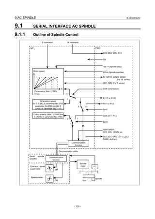
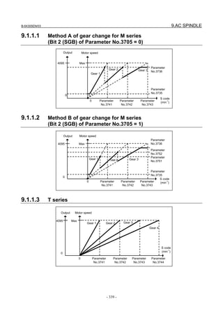
![9.AC SPINDLE B-64305EN/03
- 340 -
9.1.2 Spindle Setting and Tuning Screen
9.1.2.1 Display method
(1) Confirm the parameters
#7 #6 #5 #4 #3 #2 #1 #0
3111 SPS
[Input type] Setting input
[Data type] Bit path
#1 SPS The spindle setting screen is:
0: Not displayed.
1: Displayed.
(2) Press the function key to select the screen for setting parameters and other data.
(3) Press the continuous menu key .
(4) Press the soft key [SP.SET]. Then, the spindle setting and tuning screen appears.
(5) The following screens are provided. These screens can be selected using soft keys.
<1> [SP.SET] : Spindle setting screen
<2> [SP.TUN] : Spindle tuning screen
<3> [SP.MON] : Spindle monitor screen
(6) With the page keys , a spindle to be displayed can be selected (only when multiple
serial spindles are connected).
9.1.2.2 Spindle setting screen
- Gear selection
The gear select status on the machine side is displayed.](https://image.slidesharecdn.com/fanuc0imaintenancemanual-140802043306-phpapp01/85/Fanuc-0i-maintenance-manual-CNC-milling-machine-358-320.jpg)
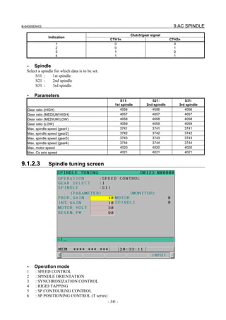
![9.AC SPINDLE B-64305EN/03
- 342 -
- Gear selection
- Spindle
The descriptions of these two items are the same as those for the spindle setting screen.
- Displayed parameters
The displayed parameters vary depending on the operation mode.
Normal
operation
Orientation
Synchronous
control
Rigid tapping Cs contour control
Spindle positioning
control (T series)
Proportional gain
Integral gain
Motor voltage
Regenerative
power
Proportional gain
Integral gain
Loop gain
Motor voltage
ORAR gain (%)
Shift spindle stop
position
Shift reference
position
Proportional gain
Integral gain
Loop gain
Motor voltage
Acceleration/
deceleration constant
Shift reference position
Proportional gain
Integral gain
Loop gain
Motor voltage
ZRN gain (%)
Shift reference position
Proportional gain
Integral gain
Loop gain
Motor voltage
ZRN gain (%)
Shift reference position
Proportional gain
Integral gain
Loop gain
Motor voltage
ZRN gain (%)
Shift reference position
*1) For the parameter numbers corresponding to the displayed parameter items, see Section 9.1.2.5.
- Displayed monitoring items
The displayed monitoring items vary depending on the operation mode.
Normal
operation
Orientation
Synchronous
control
Rigid tapping Cs contour control
Spindle positioning
control (T series)
Motor speed
Spindle speed
Motor speed
Spindle speed
Position deviation S
Motor speed
Spindle speed
Position deviation S1
Position deviation S2
Synchronous deviation
Motor speed
Spindle speed
Position deviation S
Position deviation Z
Synchronous deviation
Motor speed
Spindle speed
Position deviation S
Motor speed
Feedrate
Position deviation S
*1)
|Spindle data|
Motor speed [min-1
] =
16383
× Max. motor speed (*)
(*) Parameter No. 4020](https://image.slidesharecdn.com/fanuc0imaintenancemanual-140802043306-phpapp01/85/Fanuc-0i-maintenance-manual-CNC-milling-machine-360-320.jpg)
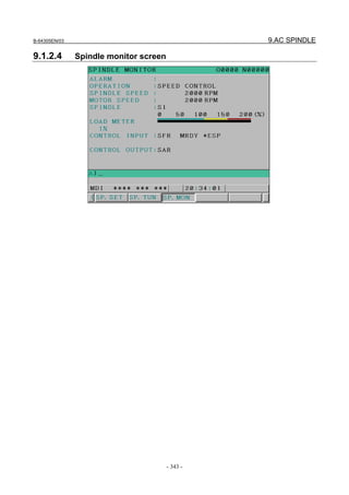
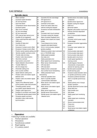
![B-64305EN/03 9.AC SPINDLE
- 345 -
f. Spindle positioning control (T series)
- Load meter
The load meter displays spindle load in a unit of 10%.
Load meter data
Load meter [%] =
32767
× Max. output value of load
meter (*)
(*) Parameter No. 4127: High-speed winding
Parameter No. 4093: Low-speed winding
- Control input signal
Max.10 signals those are ON are displayed from the following signals:
TLML
TLMH
CTH1
CTH2
SRV
SFR
ORCM
MRDY
ARST
Torque limit command (low)
Torque limit command (high)
Gear signal 1
Gear signal 2
Spindle reverse rotation
Spindle forward rotation
Spindle orientation
Machine ready
Alarm reset signal
*ESP
SOCN
RSL
RCH
INDX
ROTA
NRRO
INTG
DEFM
Emergency stop
Soft start/stop
Output switching request
Power line state confirm
Orientation stop pos. change
Rotation direction of ORCM
Short-cut of ORCM
Speed integral control signal
Differential mode command
- Control output signals
Signals those are ON are displayed from the following signals:
ALM
SST
SDT
SAR
LDT1
Alarm signal
Speed zero signal
Speed detecting signal
Speed arrival signal
Load detecting signal 1
LDT2
TLM5
ORAR
RCHP
RCFN
Load detecting signal 2
Torque limitation
Orientation end signal
Output switch signal
Output switch complete signal
9.1.2.5 Correspondence between operation mode and parameters on
spindle tuning screen
- Normal operation mode
S11:
1st spindle
S21:
2nd spindle
S31:
3rd spindle
Proportional gain (HIGH) 4040 4040 4040
Proportional gain (LOW) 4041 4041 4041
Integral gain (HIGH) 4048 4048 4048
Integral gain (LOW) 4049 4049 4049
Motor voltage 4083 4083 4083
Regenerative power 4080 4080 4080
- Orientation mode
S11:
1st spindle
S21:
2nd spindle
S31:
3rd spindle
Proportional gain (HIGH) 4042 4042 4042
Proportional gain (LOW) 4043 4043 4043
Integral gain (HIGH) 4050 4050 4050
Integral gain (LOW) 4051 4051 4051
Loop gain (HIGH) 4060 4060 4060
Loop gain (MED.HIGH) 4061 4061 4061](https://image.slidesharecdn.com/fanuc0imaintenancemanual-140802043306-phpapp01/85/Fanuc-0i-maintenance-manual-CNC-milling-machine-363-320.jpg)
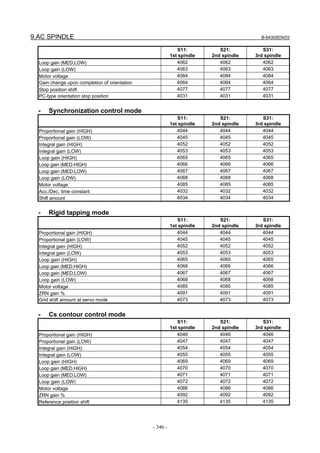
![B-64305EN/03 9.AC SPINDLE
- 347 -
- Spindle positioning control mode (T series)
S11:
1st spindle
S21:
2nd spindle
S31:
3rd spindle
Proportional gain (HIGH) 4044 4044 4044
Proportional gain (LOW) 4045 4045 4045
Integral gain (HIGH) 4052 4052 4052
Integral gain (LOW) 4053 4053 4053
Loop gain (HIGH) 4065 4065 4065
Loop gain (MED.HIG) 4066 4066 4066
Loop gain (MED.LOW) 4067 4067 4067
Loop gain (LOW) 4068 4068 4068
Motor voltage 4085 4085 4085
ZRN gain % 4091 4091 4091
Reference position shift 4073 4073 4073
9.1.3 Automatic Setting of Standard Parameters
The standard parameters related to each motor model can be set automatically.
* The specifications used to control the motor vary with the machine tool builder, but this function
also sets the parameters that determine the specifications to their default values (initial values) again.
Therefore, be sure to set the parameters correctly again with reference to a list of parameters Nos.
4000 to 4999 before performing automatic operation.
1 Turn on the power in the emergency stop state.
2 Set bit 7 of parameter 4019 to 1.
#7 #6 #5 #4 #3 #2 #1 #0
4019 LDSP
[Input type] Parameter input
[Data type] Bit spindle
#7 LDSP The parameters for the serial interface spindle are:
0: Not set automatically.
1: Set automatically.
3 Set a motor model code.
4133 Motor model code
Code Motor model Amplifier
336 βiI 3/10000 (2000/10000min
-1
) βiSVSP*-7.5
337 βiI 3/10000 (2000/10000min
-1
) βiSVSP*-11
338 βiI 3/10000 (2000/10000min
-1
) βiSVSP*-15
333 βiI 6/10000 (2000/10000min
-1
) βiSVSP*-11
339 βiI 6/10000 (2000/10000min-1
) βiSVSP*-15
341 βiI 8/10000 (2000/10000min
-1
) βiSVSP*-11
342 βiI 8/10000 (2000/10000min
-1
) βiSVSP*-15
343 βiI 12/8000 (2000/8000min
-1
) βiSVSP*-15
350 βiIP 15/6000 (1200/6000min
-1
) βiSVSP*-11
351 βiIP 15/6000 (1200/6000min
-1
) βiSVSP*-15
353 βiIP 18/6000 (1000/6000min
-1
) βiSVSP*-11
352 βiIP 18/6000 (1000/6000min
-1
) βiSVSP*-15](https://image.slidesharecdn.com/fanuc0imaintenancemanual-140802043306-phpapp01/85/Fanuc-0i-maintenance-manual-CNC-milling-machine-365-320.jpg)
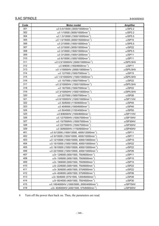
![B-64305EN/03 9.AC SPINDLE
- 349 -
9.1.4 Warning Interface
Overview
The warning state can be reported before an alarm is issued. When the warning state is entered, a report to
the PMC is sent.
For example, this signal can be used for retracting tools or reducing cutting load from the time a warning
occurs by the time an overheat alarm occurs. In addition, diagnostic information also contains warning
numbers.
Signal
Spindle warning detailed signals SPWRN1 to SPWRN9 <F264.0 to F264.7, F265.0>
[Classification] Output
[Function] Reports the warning number corresponding to the state of the αi spindle amplifier.
[Output condition] When the αi spindle is in the warning state, a warning number consisting of SPWRN1 to
SPWRN9 is output as nine-bit binary data.
If warnings occurred on multiple αi spindle amplifiers, the warning number of the αi
spindle having the smallest axis number is output.
The warning numbers and their descriptions are shown below.
Warning
number
Contents Details
01 Motor overheat When the motor temperature increases beyond the overheat warning
detection level (set by a parameter), a warning signal is output. At this
time, spindle operation is continued. So, perform necessary processing
with the PMC.
An alarm is issued when the motor temperature has reached the
overheat alarm detection level.
04 Open-phase detected in the
converter main power supply
If an open-phase is detected in the main power supply, the warning
signal is output. Since the spindle continues to operate at this time,
use the PMC to perform processing as needed.
About one minute (for the αiPS) or about five seconds (for the αiPSR)
after the warning signal is output, an alarm occurs.
06 Temperature sensor error Coolant entered the spindle motor, probably reducing insulating
resistance. Remove coolant. Take measures to prevent coolant
from entering the motor. If insulating resistance is in advanced
stages, the motor needs to be replaced.
56 Internal fan stopped If the internal fan stops, the warning signal is output. Since the spindle
continues to operate at this time, use the PMC to perform processing
as needed.
About one minute after the warning signal is output, an alarm occurs.
58 Converter main circuit
overloaded
If the main circuit of the Power Supply (PS) is overloaded, the warning
signal is output. Since the spindle continues to operate at this time,
use the PMC to perform processing as needed.
About one minute after the warning signal is output, an alarm occurs.
59 Converter cooling fan stopped If the Power Supply (PS) cooling fan stops, the warning signal is
output. Since the spindle continues to operate at this time, use the
PMC to perform processing as needed.
About one minute after the warning signal is output, an alarm occurs.
88 Radiator cooling fan stopped If the radiator cooling fan stops, the warning signal is output. Since the
spindle continues to operate at this time, use the PMC to perform
processing as needed.
If the main circuit overheats, an alarm occurs.
113 Converter radiator cooling fan
stopped
If the Power Supply (PS) radiator cooling fan stops, the warning signal
is output. Since the spindle continues to operate at this time, use the
PMC to perform processing as needed.
If the Power Supply (PS) main circuit overheats, an alarm occurs.](https://image.slidesharecdn.com/fanuc0imaintenancemanual-140802043306-phpapp01/85/Fanuc-0i-maintenance-manual-CNC-milling-machine-367-320.jpg)
![9.AC SPINDLE B-64305EN/03
- 350 -
Signal address
#7 #6 #5 #4 #3 #2 #1 #0
F264 SPWRN8 SPWRN7 SPWRN6 SPWRN5 SPWRN4 SPWRN3 SPWRN2 SPWRN1
F265 SPWRN9
Diagnosis screen
The status of a warning is displayed on the following diagnostic screen.
712 Warning status of spindle
[Data type] Word spindle
The number of a warning caused on each spindle is indicated.
If there is no warning, 0 is indicated.
9.1.5 Spindle Information Screen
Overview
ID information output from each of the connected units is obtained and output to the CNC screen.
The units that have ID information are shown below.
• Spindle amplifier (SP)
• Power Supply (PS)
ID information is automatically read from each of the connected units during first startup of the CNC and
then recorded. During second or later startup, the ID information recorded during first startup can be
compared with the ID information read this time on the screen to check whether the configuration of the
connected units is changed. (If there is a difference between them, the alarm mark (*) appears.)
The recorded ID information can be edited. Therefore, the ID information of an unit that does not have ID
information can be displayed. (However, the alarm mark (*) indicating a difference between these IDs
appears.)
Parameter
#7 #6 #5 #4 #3 #2 #1 #0
13112 SPI IDW
[Input type] Parameter input
[Data type] Bit path
#0 IDW Editing on the servo or spindle information screen is:
0: Prohibited.
1: Not prohibited.
#2 SPI The servo information screen is:
0: Displayed.
1: Not displayed.
Displaying the spindle information screen
1 Press the function key, then press the [SYSTEM] soft key.
2 Press the [SPINDLE] soft key to display the screen as shown below.](https://image.slidesharecdn.com/fanuc0imaintenancemanual-140802043306-phpapp01/85/Fanuc-0i-maintenance-manual-CNC-milling-machine-368-320.jpg)
![B-64305EN/03 9.AC SPINDLE
- 351 -
* Spindle information is stored in flash ROM. If there is a difference between the ID information
in screen and the actual ID information, the corresponding items are preceded by *, as shown
below.
Additional Information
Even if replacement is performed reasonably such as for repairing, this function
incorrectly indicates the * mark when it detects the replacement.
To clear the * mark, follow the steps below to update the registered data, as
described in the editing section later.
(1) Make the registered data editable. (Bit 0 (IDW) of parameter No. 13112 = 1)
(2) On the edit screen, place the cursor on the item from which you want to
delete the * mark.
(3) Operate the soft keys [READ ID], [INPUT], and [SAVE] in that order.](https://image.slidesharecdn.com/fanuc0imaintenancemanual-140802043306-phpapp01/85/Fanuc-0i-maintenance-manual-CNC-milling-machine-369-320.jpg)
![9.AC SPINDLE B-64305EN/03
- 352 -
Editing the spindle information screen
1 Assume that bit 0 (IDW) of parameter No. 13112 = 1.
2 Press the MDI switch on the machine operator's panel.
3 Follow the steps shown in "Displaying the spindle information screen" to display the screen as
shown below.
4 To move the cursor on the screen, use cursor keys .
Screen operation
Mode Key operation Use
Viewing (*1) Page key Scrolls up or down on a screen-by-screen basis.
Soft key
[INPUT] Replace the selected ID information at the cursor position with the character string
in key-in buffer.
[CANCEL] Deletes the character string in key-in buffer.
[READ ID] Transfers the ID information the connected device at the cursor has to the key-in
buffer. Only the items preceded by * (*3) are valid.
[SAVE] Saves the ID information that has been changed on the spindle information screen
in flash ROM.
[RELOAD] Cancels the ID information that has been changed on the spindle information
screen and loads ID information from flash ROM.
Page key Scrolls up or down on a screen-by-screen basis.
Editing (*2)
Cursor key Scrolls up or down the selection of ID information.
*1 Viewing mode: when bit 0 (IDW) of parameter No. 13112 = 0
*2 Editing mode: when bit 0 (IDW) of parameter No. 13112 = 1
*3 Spindle information is stored in flash ROM. If there is a difference between the ID information in
screen and the actual ID information, the corresponding items are preceded by *.](https://image.slidesharecdn.com/fanuc0imaintenancemanual-140802043306-phpapp01/85/Fanuc-0i-maintenance-manual-CNC-milling-machine-370-320.jpg)
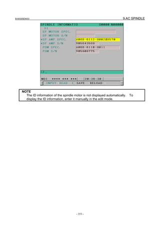

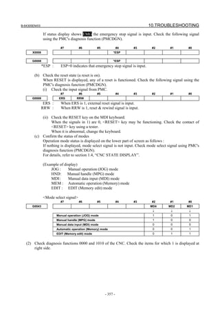
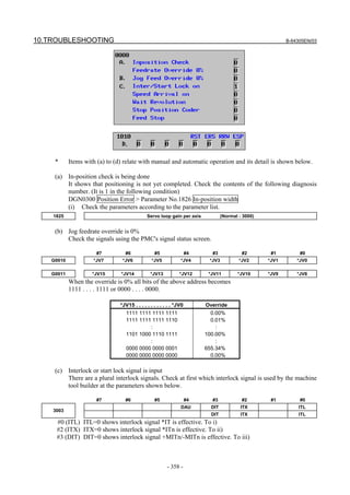
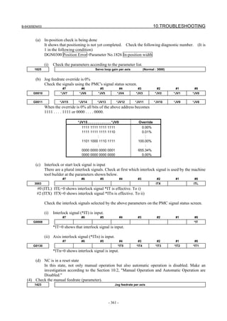
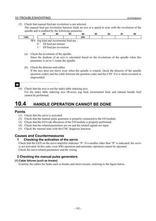
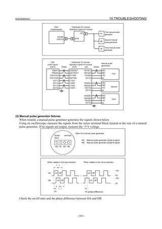
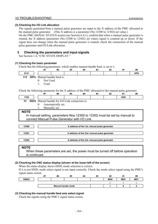
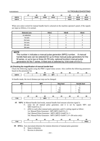

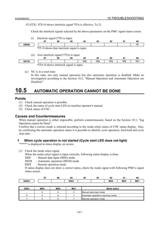
![10.TROUBLESHOOTING B-64305EN/03
- 368 -
(2) Check the automatic operation start signal.
The automatic operation start signal is set to 1 when the automatic operation start button is pressed
or 0 when the automatic operation start button is released. Automatic operation is started when this
signal is changed from 1 to 0, so check the status of the signal on the PMC signal status screen.
#7 #6 #5 #4 #3 #2 #1 #0
G0007 ST
ST : Cycle start signal
(3) Check the automatic operation stop (feed hold) signal.
During normal operation, when the automatic operation stop button is not pressed, the automatic
operation stop (feed hold) signal is 1. So, check the signal status on the PMC signal status screen.
#7 #6 #5 #4 #3 #2 #1 #0
G0008 *SP
*SP : Feed hold signal
2 When an automatic operation is in progress (Cycle start LED is lit)
CNC's status display shows "STRT" on the screen.
(1) Check information displayed with CNC diagnosis number 0000. Check the items for which 1 is
displayed on the right side.
Diagnosis 0000 CNC internal state 1
[Data type] Bit
NAME Internal state when "1" is displayed
(a) In-position Check In-position check is being done.
(b) Feedrate Override 0% Feedrate override is 0%.
(c) Jog Feed Override 0% Jog feedrate override is 0%.
(d) Inter/Start Lock on Interlock/start lock is on.
(e) Speed Arrival on The system is waiting for the speed arrival signal to turn on.
Wait Revolution The system is waiting for the spindle one-rotation signal in
threading.
Stop Position Coder The system is waiting for the rotation of the position coder
in spindle feed per revolution.
Feed Stop A feed stop was made.
* Items with (a) to (e) relate with an automatic operation and their details are as follows :
(a) In-position check (confirming positioning) is being done
In positioning (G00) of the corresponding axis, the specified position is not reached.
Whether positioning is completed or not is checked as the servo position error amount. So,
use the following diagnosis function to check this.
DGN 300 Position error > Parameter No.1826 In-position width
Position error amount almost becomes 0, when positioning of an axis completes and when the
amount becomes within the in-position width, it is assumed that positioning completes and the
next block is executed.
(b) Feedrate override is at 0%
Actual feedrate is overridden by the override signals to a programmed feedrate. Check the
override signals using the PMC's signal status screen.
• Feedrate override signal
#7 #6 #5 #4 #3 #2 #1 #0
G0012 *FV7 *FV6 *FV5 *FV4 *FV3 *FV2 *FV1 *FV0
*FVn : Feedrate override](https://image.slidesharecdn.com/fanuc0imaintenancemanual-140802043306-phpapp01/85/Fanuc-0i-maintenance-manual-CNC-milling-machine-386-320.jpg)
![B-64305EN/03 10.TROUBLESHOOTING
- 369 -
• State of override signal
*FV7 . . . . . *FV0
1 1 1 1 1 1 1 1 0%
1 1 1 1 1 1 1 0 1%
: :
1 0 0 1 1 0 1 1 100%
: :
0 0 0 0 0 0 0 1 254%
0 0 0 0 0 0 0 0 0%
(c) Manual feedrate override is 0% (dry run)
Normally manual feedrate override function is used for jog feed.
But when DRN(dry run) signal turns on during an automatic operation, override values set with
these signals become valid to the following speed set by a parameter.
#7 #6 #5 #4 #3 #2 #1 #0
G0046 DRN
Dry run signal is input with this signal being 1.
1410 Dry run rate
When the value of the following override signal is 100%, the set feedrate is achieved.
#7 #6 #5 #4 #3 #2 #1 #0
G0010 *JV7 *JV6 *JV5 *JV4 *JV3 *JV2 *JV1 *JV0
G0011 *JV15 *JV14 *JV13 *JV12 *JV11 *JV10 *JV9 *JV8
When override value is 0%, all bits of the above address is
[1111 . . . . 1111] or [0000 . . . . 0000].
*JV15 . . . . . . . . . . . . . . . . . . . . . . *JV0 Override
1111 1111 1111 1111 0.00%
1111 1111 1111 1110 0.01%
: :
1101 1000 1110 1111 100.00%
: :
0000 0000 0000 0001 655.34%
0000 0000 0000 0000 0.00%
(d) Interlock signal is input
Some interlock functions are provided; the interlock signal to be used is set by the machine tool
builder with the parameter. So, check the following settings first.
#7 #6 #5 #4 #3 #2 #1 #0
3003 ITX ITL
#0 (ITL) ITL=0 shows interlock signal *IT is effective. To i)
#2 (ITX) ITX=0 shows interlock signal *ITn is effective. To ii)
Check the interlock signals selected by the above parameters on the PMC signal status screen.
(i) Interlock signals (*IT, *CSL, and *BSL) are input.
#7 #6 #5 #4 #3 #2 #1 #0
G0008 *BSL *CSL *IT
*IT=0, *CSL=0, and *BSL=0 show that interlock signal is input.
(ii) Interlock signal per each axis (*ITn) is input
#7 #6 #5 #4 #3 #2 #1 #0
G0130 *IT5 *IT4 *IT3 *IT2 *IT1
When the bit is 0, the corresponding axis's interlock signal is input.](https://image.slidesharecdn.com/fanuc0imaintenancemanual-140802043306-phpapp01/85/Fanuc-0i-maintenance-manual-CNC-milling-machine-387-320.jpg)
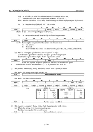
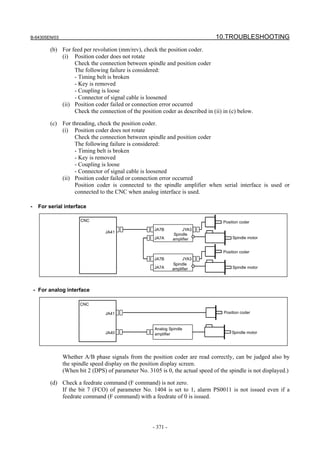
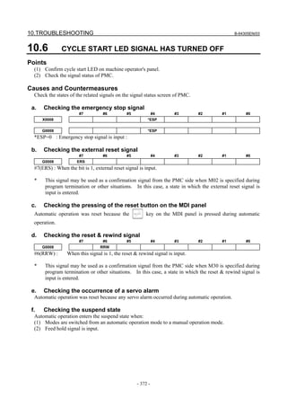
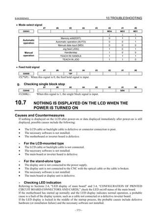
![10.TROUBLESHOOTING B-64305EN/03
- 374 -
- Checking the LCD cable and backlight cable
Check that the LCD and backlight cables are connected firmly to the corresponding connectors.
These cables are connected before shipment from FANUC. This check is, however, required because the
cables may be disconnected during maintenance.
- Checking the installation of the necessary software
If necessary software is not stored in the FROM module, the CNC may not start up.
- Checking a failure of printed-circuit boards
If the main board fails, the CNC may not start up.
Confirm that printed-circuit boards are securely connected through connectors.
If any of the above actions does not solve the problem, replace the inverter board or main board.
10.8 INPUT FROM AND OUTPUT TO I/O DEVICES CANNOT BE
PERFORMED, INPUT/OUTPUT CANNOT BE PERFORMED
PROPERLY
Causes and Countermeasures
If the I/O Link is not established, if the signals from an I/O device cannot be input normally to the CNC,
or if the signals from the CNC cannot be output to an I/O device, the probable causes include the
following:
• The I/O device is not turned on, or the power supply is not at the appropriate voltage.
• The I/O Link cable is not connected correctly or appropriately.
• The grounding is not correct.
• The input/output signals are not connected correctly.
• I/O Link allocation is not performed, or is not performed properly.
- Checking PMC alarms
ER32 NO I/O DEVICE
If "ER32 NO I/O DEVICE" is displayed on the alarm screen of the PMC, no I/O devices are recognized.
ER97 IO LINK FAILURE
If "ER97 I/O LINK CONNECTION ERROR CHxx yyGROUP" appears on the PMC alarm screen, the
setting of the I/O device connection count in channel xx of I/O Link does not match the I/O Link
connection count that was allocated actually.
- Checking the PMC I/O Link screen
Press function key , soft key [PMCMNT], and soft key [I/O LNK]. The I/O devices recognized by
the CNC are displayed. From this screen, the devices that are connected normally can be determined.](https://image.slidesharecdn.com/fanuc0imaintenancemanual-140802043306-phpapp01/85/Fanuc-0i-maintenance-manual-CNC-milling-machine-392-320.jpg)
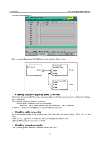
![10.TROUBLESHOOTING B-64305EN/03
- 376 -
- Checking I/O connection
Check that the input/output signals to be connected to each I/O device are connected correctly.
For operator's panel I/O modules and for connector panel I/O modules, also check that the 0 V or +24 V
input signal is connected to the common pin and that the +24 V output signal is connected to the DO
common pin.
- Checking I/O Link allocation
Check that I/O Link allocation has been performed correctly.
Press function key , soft key [PMCCNF], soft key [MODULE], and soft key [EDIT]. The
allocation edit screen appears.
After editing allocation, be sure to write the sequence program onto the flash ROM using the PMC data
I/O screen. Otherwise, the changes will be lost when the power is turned off.
10.9 IN A CONNECTOR PANEL I/O UNIT, DATA IS INPUT TO
AN UNEXPECTED ADDRESS
If data is input to an invalid address in a connector panel I/O unit (for example, data that should be input
to X004 is actually input to X010 in a connector panel I/O unit), the most likely causes are as follows:
(1) The I/O Link allocation is wrong.
→ Perform the check described in Section 10.8.
(2) The unit-to-unit cables (CA52-to-CA53) are not connected correctly.
If the connection is wrong, expansion unit 1 is allocated the address of expansion unit 3, as shown
below.
→ Connect the unit-to-unit cables as shown below:
Correct connection (the allocation starts with X0)
Incorrect connection (the allocation starts with X0)
CA53 CA52CA52 CA53 CA52 CA53
CA52 CA52 CA53 CA53 CA52 CA53
Basic Expansion 1 Expansion 2 Expansion 3
Basic Expansion 1 Expansion 2 Expansion 3
X0-2 X3-5 X6-8 X9-11
X0-2 X9-11 X6-8 X3-5
(3) The setting of the rotary switch on an expansion unit is wrong
If the rotary switch is set to 1, one unit number is skipped. If set to 2, two unit numbers are skipped.
Usually, the setting must be 0. (For those units without a rotary switch, unit numbers cannot be
skipped.)
→ See the following example and refer to the Section 4.6, “SETTING I/O MODULES.”](https://image.slidesharecdn.com/fanuc0imaintenancemanual-140802043306-phpapp01/85/Fanuc-0i-maintenance-manual-CNC-milling-machine-394-320.jpg)
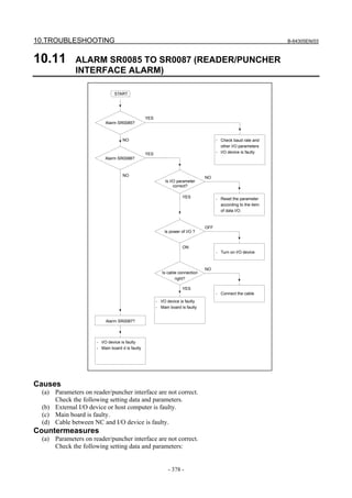
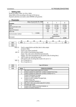
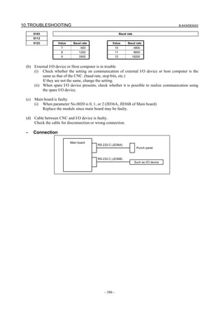
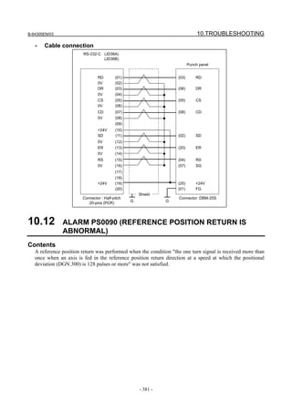
![10.TROUBLESHOOTING B-64305EN/03
- 382 -
Countermeasures
F×5000/3
START
Check whether the positional error amount (No. 300 value on the
diagnosis screen) in the reference position return direction is 128 or
more during a reference position return or during axis movement
before a reference position return
Position error
amount : DGN
300
128 or more
YES
NO
(1) Next page
Raise the speed
Check feed rate command:
Parameter No. 1420 F : Rapid traverse rate [mm/min]
Parameter No. 1424 Manual rapid traverse rate [mm/min]
Parameter No. 1825 G : Servo loop gain [0.01sec
-1
]
Detection unit : Move amount to a command pulse
G × detection unit [μm/PULSE]
Check reference position return deceleration signal
*DEC1 to *DEC5 X009.0 to X009.4
When reference position return is started from deceleration signal 0, feed
rate becomes FL rate.
Parameter No. 1425 FL rate
Position error =
Check rapid traverse override signals :
ROV1 G014.0
ROV2 G014.1
Parameter No. 1421 F0 rate
ROV1 ROV2 Override
0 0 100%
0 1 50%
1 0 25%
1 1 F0 rate](https://image.slidesharecdn.com/fanuc0imaintenancemanual-140802043306-phpapp01/85/Fanuc-0i-maintenance-manual-CNC-milling-machine-400-320.jpg)
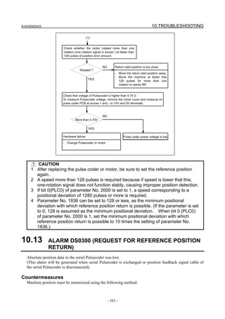
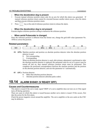
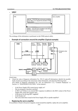
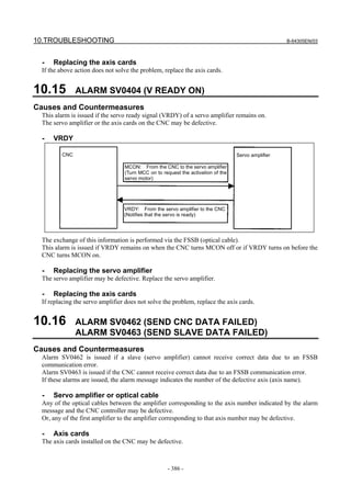
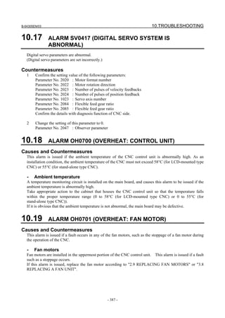
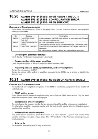
![B-64305EN/03 10.TROUBLESHOOTING
- 389 -
10.22 SERVO ALARMS (SV04**, SV06**)
For an explanation of the following servo alarms, refer to the FANUC AC SERVO MOTOR αi series,
AC SPINDLE MOTOR αi series, SERVO AMPLIFIER αi series Maintenance Manual (B-65285EN).
Number Message Description
SV0417 ILL DGTL SERVO PARAMETER A digital serve parameter setting is incorrect.
[When bit 4 of diagnosis information No. 203 is 1.]
An illegal parameter was detected by the servo software. Identify
the cause with reference to diagnosis information No. 352.
[When bit 4 of diagnosis information No. 203 is 0.]
The CNC software detected an illegal parameter. Probable
causes are given below (see diagnosis information No. 280).
1) The value specified in parameter No. 2020 as the motor model
falls outside the specified range.
2) The motor rotation direction in parameter No. 2022 is not set to
a correct value (111 or -111).
3) The speed feedback pulse count per motor rotation in
parameter No. 2023 is set to a negative or other incorrect value.
4) The position feedback pulse count per motor rotation in
parameter No. 2024 is set to a negative or other incorrect value.
SV0420 SYNC TORQUE EXCESS In feed axis control , for synchronization, the difference value of
torque between a master and slave axes exceeded the parameter
(No. 2031) setting value. This alarm occurs for a master axis.
SV0421 EXCESS ERROR(SEMI-FULL) The difference between the feedback from the semi and full sides
exceeded the setting of parameter No.1729.
SV0422 EXCESS VELOCITY IN
TORQUE
In torque control, the commanded permissible velocity was
exceeded.
SV0423 EXCESS ERROR IN TORQUE In torque control, the total permissible move value specified as a
parameter was exceeded.
SV0430 SV MOTOR OVERHEAT The servo motor has overheated.
SV0431 CNV. OVERLOAD Power Supply (PS) : Overheat
Servo Amplifier : Overheat
SV0432 CNV. LOW VOLT CONTROL Power Supply (PS) : The control power supply voltage has
dropped.
Servo Amplifier : The control power supply voltage has
dropped.
SV0433 CNV. LOW VOLT DC LINK Power Supply (PS) : Low DC link voltage
Servo Amplifier : Low DC link voltage
SV0434 INV. LOW VOLT CONTROL Servo Amplifier : Low control power voltage
SV0435 INV. LOW VOLT DC LINK Servo Amplifier : Low DC link voltage
SV0436 SOFTTHERMAL(OVC) The digital servo software detected a software thermal (OVC).
SV0437 CNV. OVERCURRENT POWER Power Supply (PS) : Overcurrent on input circuit section.
SV0438 INV. ABNORMAL CURRENT Servo Amplifier : Motor overcurrent
SV0439 CNV. OVER VOLT DC LINK Power Supply (PS) : The DC link voltage is too high.
Servo Amplifier : The DC link voltage is too high.
SV0440 CNV. EX DECELERATION
POW.
Power Supply (PS) : Excessive generative discharge
Servo Amplifier : Excessive generative discharge, or
abnormal error in generative power circuit
SV0441 ABNORMAL CURRENT
OFFSET
The digital servo software detected an abnormality in the motor
current detection circuit.
SV0442 CNV. CHARGE FAILURE Power Supply (PS) : The spare charge circuit for the DC link is
abnormal.
SV0443 CNV. COOLING FAN FAILURE Power Supply (PS) : Internal cooling fan failure.
Servo Amplifier : Internal cooling fan failure.
SV0444 INV. COOLING FAN FAILURE Servo Amplifier : Internal cooling fan failure.](https://image.slidesharecdn.com/fanuc0imaintenancemanual-140802043306-phpapp01/85/Fanuc-0i-maintenance-manual-CNC-milling-machine-407-320.jpg)
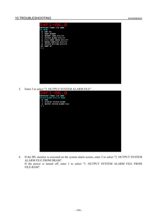
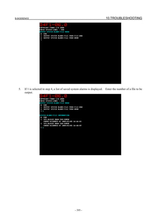
![10.TROUBLESHOOTING B-64305EN/03
- 396 -
6. Enter the name of a file to be output to the memory card and output the file.
10.25.3 System Alarms Detected by Hardware
System alarm 400 and subsequent system alarms indicate errors detected by hardware.
The basic screen configuration is shown below:
[Description of the message screen]
(1): Device name, and series and edition of CNC system software
(2): System alarm number and error message
(3): Most possibly faulty component
(4): Date and time when the error occurred
D4F1 ー 01.0
SYS_ALM401 EXTERNAL BUS INVALID ADDRESS
MAIN BOARD
2008/04/22 17:09:53
PROGRAM COUNTER : 1000B52CH
ACT TASK : 01000010H
ACCESS ADDRESS : -
ACCESS DATA : -
ACCESS OPERATION : -
BUS MASTER PCB : ETC
+--+----------+-----------------------------------------------------+
02 ETC 03012003 22110000 80010000 00000000 00010000 00000000
FFFFFFFF FFFFFFFF 68C08216 70FE0000 00000000 00000000
00000000 00000000 00000000 00000000 00000000
BUS SLAVE PCB : CPU
+--+----------+-----------------------------------------------------+
00 CPU 02071004 20100000 00000000 00000000 00000000 00000000
FFFFFFFF FFFFFFFF 10B0FC00 CFF90001 68C30061 82160010
000000F0 00000000 00010000 00000000 00000000
INFORMATION REGISTER
+--+----------+-----------------------------------------------------+
02 ETC 00000000 00000000 00000000 00000000
PAGE UP OR DOWN (PAGE 1/8)
(1)
(2)
(3)
(4)
(5)
|
|
|
↓
(6)
|
|
|
|
|
|
|
|
|
|
|
|
|
↓](https://image.slidesharecdn.com/fanuc0imaintenancemanual-140802043306-phpapp01/85/Fanuc-0i-maintenance-manual-CNC-milling-machine-414-320.jpg)
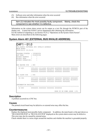
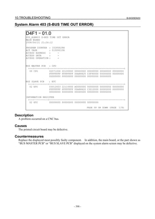
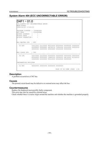
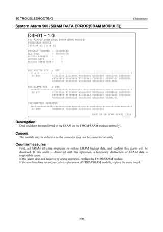
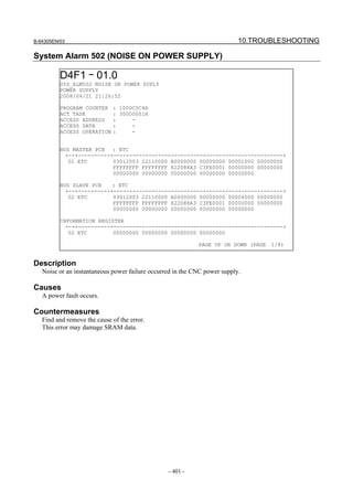
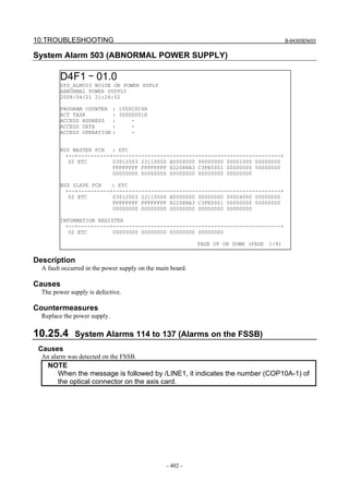
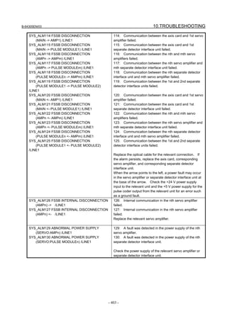
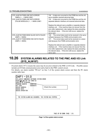
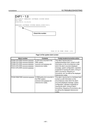
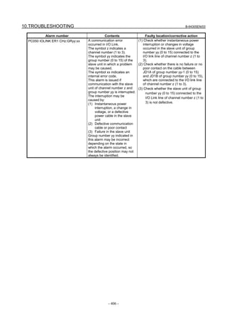
![B-64305EN/03 10.TROUBLESHOOTING
- 407 -
Alarm number Contents Faulty location/corrective action
PC051 IOLINK ER2 CHz:yy:xx:ww:vv A communication error
occurred in I/O Link.
A communication error
occurred on channel z of I/O
Link.
Symbol z indicates a channel
number (1 to 3).
Symbols yy, xx, ww, and vv
are internal error codes.
This alarm is issued by various
factors related to I/O Link.
The cause of the
communication error needs to
be considered in view of this
message and other situations.
Therefore, please notify
FANUC of the situation in
which the error occurred (such
as the displayed message,
system configuration,
operation, occurrence timing,
and frequency of occurrence)
and the internal error code
displayed.
(1) When using the I/O Unit-MODEL A,
even though the base expansion has
been allocated, no base is not
connected. Check whether the units
actually connected follow the I/O Link
allocation.
(2) When the Power Mate or Servo Motor
b series I/O Link option was connected
as an I/O slave unit, check whether a
system alarm occurred first in any of
these units.
(3) Check whether noise is generated on
the communication line. Check the
grounding state of I/O Link slave units
and the shielding state of connected
cables.
(4) Check whether the DO output of I/O
units is not short-circuited.
(5) Check whether instantaneous power
interruption or changes in voltage
occurred in the power for I/O Link
master and slave units.
(6) Check that there is no failure in cable
connection.
(7) Check that there is no defect in
cables.
(8) Check that the ground terminals of I/O
units and the shield wires of
communication cables are properly
grounded.
(9) Replace the I/O Link slave units.
(10) Replace the PMC module.]
(For information on noise and grounding,
refer to the antinoise measure chapter in
the Connection Manual (Hardware)
(B-64303EN).
PC060 BUS xxxxxxxx:yyyyyyyy A bus error occurred in the
PMC system.
This alarm may be due to a
software/hardware fault; contact us with
information on the circumstances under
which the alarm occurred (displayed
message, system configuration, operation
suspected of causing the alarm, timing of
alarm occurrence, frequency of
occurrence, etc.) as well as the displayed
internal error codes.
PC070 LADDER SPE (PMCn) A stack error occurred with the
SPE functional instruction of
the ladder program of n path.
Check the correspondence between the
CALL or CALLU instruction and the SPE
instruction.
PC097 LADDER PARITY
ERR(PMCn)
PC098 CODE PARITY ERR
A RAM check error occurred. This alarm may be due to a hardware fault;
contact us with information on the
circumstances under which the alarm
occurred (displayed message, system
configuration, operation suspected of
causing the alarm, timing of alarm
occurrence, frequency of occurrence, etc.).](https://image.slidesharecdn.com/fanuc0imaintenancemanual-140802043306-phpapp01/85/Fanuc-0i-maintenance-manual-CNC-milling-machine-425-320.jpg)
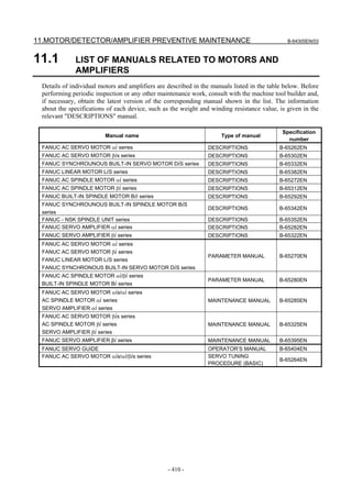
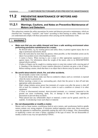
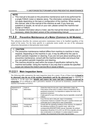
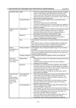
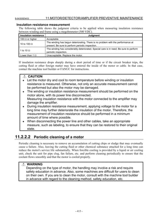


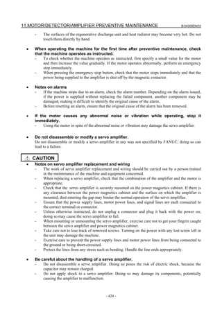
![B-64305EN/03 11.MOTOR/DETECTOR/AMPLIFIER PREVENTIVE MAINTENANCE
- 427 -
11.3.3 Maintenance of a Servo Amplifier
11.3.3.1 Display of the servo amplifier operation status
The STATUS LEDs on the front of the servo amplifier indicate the operation status of the servo amplifier
(whether it is operating normally, the type of alarm, etc.). Use these LEDs for maintenance, inspection,
troubleshooting, etc.
CAUTION
A servo amplifier failure may arise from a combination of multiple causes, in
which case it can be difficult to identify all those causes. Handling the failure in
an improper way may worsen the problem. It is therefore important to analyze
the failure status minutely and identify the true cause or causes of the failure.
There may be cases in which the failure appears to have been fixed but later
recurs or cause a more serious trouble. If you are not sure about the root cause
of or corrective action for a failure, do not act on your own; please contact the
machine tool builder or FANUC for instructions on proper action.
[αi series]
(1) Power supply
STATUS LED position
STATUS
display
Description
The STATUS LED is off.
Control power has not been supplied, cable is faulty, or control
power circuit is defective.
Not ready status
The main circuit is not supplied with power (magnetic contactor is
off); emergency stop state.
Ready status
The main circuit is supplied with power (magnetic contactor is on);
the power supply is ready for operation.
Warning state (The dot at the lower right lights.)
The power supply has failed; an alarm has occurred after a certain
time of operation.
The warning type is indicated by the character displayed.
Nameplate
Alarm status
The alarm type is indicated by the character displayed.](https://image.slidesharecdn.com/fanuc0imaintenancemanual-140802043306-phpapp01/85/Fanuc-0i-maintenance-manual-CNC-milling-machine-445-320.jpg)
![11.MOTOR/DETECTOR/AMPLIFIER PREVENTIVE MAINTENANCE B-64305EN/03
- 428 -
(2) Servo amplifier
STATUS LED
position
STATUS
display
Description
The STATUS LED is off.
Control power has not been supplied, cable is faulty, or control
power circuit is defective.
Blink
The control power is short-circuited (- blinks).
Cable failure
Waiting for the READY signal from the CNC.
Ready status
The servo motor is excited.
Nameplate
Alarm status
The alarm type is indicated by the character displayed.
(3) Spindle amplifier
STATUS LED
position
STATUS
display
Description
The STATUS LED is off.
Control power has not been supplied, cable is faulty, or control
power circuit is defective.
After control power is turned on, the spindle software series is
displayed (for approx. 1 second).
The last two digits of the spindle software series number are
displayed.
The spindle software version is displayed (for approx. 1 second
following the display of the spindle software series).
[Display] 01,02,03, ... → [Version] A, B, C, ...
Blink Blink
The CNC is not powered on (- - blinks).
Waiting for serial communication and parameter loading
completion.
Parameter loading completed
The motor is not excited.
Ready status
The spindle motor is excited.
Alarm status
The alarm type is indicated by the character displayed.
Nameplate
Error status (invalid sequence or parameter setting error)
The error type is indicated by the character displayed.](https://image.slidesharecdn.com/fanuc0imaintenancemanual-140802043306-phpapp01/85/Fanuc-0i-maintenance-manual-CNC-milling-machine-446-320.jpg)
![B-64305EN/03 11.MOTOR/DETECTOR/AMPLIFIER PREVENTIVE MAINTENANCE
- 429 -
(yellow)
(yellow)
(green)
(yellow)
(yellow)
(green)
[βi SV series]
[βi SVSP series]
βi SVSP (#A/ #C) βi SVSP (#D/ #H560/ #H580)
STATUS 2
(Servo)
STATUS 1
(Spindle)
Note) The locate or the shape of the connector and
so on may be different from the real amplifier.
STATUS 2
(Servo)
STATUS 1
(Spindle)
Note) The locate or the shape of the connector and
so on may be different from the real amplifier.
STATUS1 display
(Spindle)
Description
The STATUS LED is off.
Control power has not been supplied, cable is faulty, or control power circuit is
defective.
After control power is turned on, the spindle software series is displayed (for approx.
1 second).
The last two digits of the spindle software series number are displayed.
The spindle software version is displayed (for approx. 1 second following the display
of the spindle software series).
[Display] 01,02,03, ... → [Version] A, B, C, ...
The CNC is not powered on (- - blinks).
Waiting for serial communication and parameter loading completion.
Parameter loading completed
The motor is not excited.
Ready status
The spindle motor is excited.
STATUS LED Description
None of the LEDs is on.
Control power has not been supplied, cable is faulty, or
control power circuit is defective.
The ALM LED (yellow) is on.
Alarm status
The alarm type is indicated by the character displayed.
The LINK LED (green) is on.
Communication between CNC and servo amplifier is
progressing normally.
The POWER LED (green) is on. The control power of the servo amplifier (5 V) is normal.](https://image.slidesharecdn.com/fanuc0imaintenancemanual-140802043306-phpapp01/85/Fanuc-0i-maintenance-manual-CNC-milling-machine-447-320.jpg)
![11.MOTOR/DETECTOR/AMPLIFIER PREVENTIVE MAINTENANCE B-64305EN/03
- 430 -
STATUS1 display
(Spindle)
Description
Alarm status
The alarm type is indicated by the character displayed.
Error status (invalid sequence or parameter setting error)
The error type is indicated by the character displayed.
STATUS2 display
(Servo)
Description
The STATUS LED is off.
Control power has not been supplied, cable is faulty, or control power circuit is
defective.
Waiting for the READY signal from the CNC.
Ready status
The servo motor is excited.
Alarm status
The alarm type is indicated by the character displayed.
11.3.3.2 Replacement of a fan motor
[αi series]
(1) Fan motor for internal cooling
Replace the internal fan motor, according to the procedure shown in the figure below.
When replacing the fan motor, be careful about the direction of the fan motor (air blow direction),
the direction of the connector, etc.
Air blow direction
Fan unit
(1) Hold the two tabs
and get the fan unit
off the latch.
Tab
Fan unit (60-mm-wide)
White Black Red
Be careful about the
connector key direction.
(2) Remove the fan
unit by pulling it
upward.
Tab
Fan unit (90-mm-wide)
Fan unit (150-mm-wide)
Be careful about the
connector key direction.
Red
Black
White
* Be careful about the fan motor and connector directions.](https://image.slidesharecdn.com/fanuc0imaintenancemanual-140802043306-phpapp01/85/Fanuc-0i-maintenance-manual-CNC-milling-machine-448-320.jpg)
![B-64305EN/03 11.MOTOR/DETECTOR/AMPLIFIER PREVENTIVE MAINTENANCE
- 431 -
(2) Fan motor for cooling external heat sink
<1> Remove the two sheet metal mounting screws (for the 60-mm-wide model only), and detach the
fan motor from the unit together with the sheet metal.
<2> Remove the fan motor mounting screws (two for one fan motor and four for two fan motors).
<3> Remove the connector mounting screws (two and four for the 300-mm-wide model).
When replacing the fan motor, be careful about the direction of the fan motor (air blow direction),
the direction of the connector, etc.
Air blow
direction
60 mm wide/90 mm wide
Sheet metal mounting screws
Connector mounting screw
Fan motor
mounting screw
Air blow
direction
150 mm wide
Connector mounting screw
Fan motor
mounting screw
Air blow
direction
300 mm wide
Connector mounting screw
Fan motor
mounting screw
[βi series]
Replace the fan motor, according to the procedure shown in the figure below.
When replacing the fan motor, be careful about the direction of the fan motor (air blow direction), the
direction of the connector, etc.
White Black Red
Fan connector
Fan connector
Fan motor mounting notch
Top view of the amplifier
(4) Lift the fan unit
toward you.
(1) Pull up the fan
connector to
remove it.
(2) Push down
the fan unit
to get it off
the hooks.
(3) Set the fan unit
loose.
Air blow direction
Fan unit
βiSV4, 20 (internal fan)
Air blow direction
Fan unit
Fan unit
(2) Pull the fan unit
upward.
(1) Push the hooks to set
the fan unit loose.
βiSV40, 80 (internal fan)
Air blow
direction
(2) Pull out the fan
unit.
(1) Remove four M4
screws.
βiSV40, 80 (external fan)
Be careful about the
connector key direction.](https://image.slidesharecdn.com/fanuc0imaintenancemanual-140802043306-phpapp01/85/Fanuc-0i-maintenance-manual-CNC-milling-machine-449-320.jpg)


![A.ALARM LIST APPENDIX B-64305EN/03
- 438 -
Number Message Description
0046 ILLEGAL REFERENCE RETURN
COMMAND
A command for a return to the second, third or fourth
reference position is error. (The address P command is in
error.)
0050 CHF/CNR NOT ALLOWED IN THRD
BLK
The chamfering or corner R block is specified in a threading
block. Modify the program.
0051 MISSING MOVE AFTER CNR/CHF The travel or travel distance is incorrect in the block next to
the chamfering or corner R. Modify the program.
0052 CODE IS NOT G01 AFTER
CHF/CNR
T
The block next to the chamfering or corner R block is not G01
(or vertical line). Modify the program.
0053 TOO MANY ADDRESS COMMANDS T
In the chamfering and corner R commands, two or more of I,
J, K and R are specified.
0054 NO TAPER ALLOWED AFTER
CHF/CNR
T
A block in which chamfering in the specified angle or the
corner R was specified includes a taper command. Modify the
program.
0055 MISSING MOVE VALUE IN
CHF/CNR
The travel distance specified in the chamfering or corner R
block is smaller than the amount of the chamfering or corner
R. Modify the program.
0056 NO END POINT & ANGLE IN
CHF/CNR
T
In direct dimension drawing programming, both an end point
and an angle were specified in the block next to the block in
which only an angle was specified (Aa). Modify the program.
0057 NO SOLUTION OF BLOCK END T
Block end point is not calculated correctly in direct dimension
drawing programming. Modify the program.
0058 END POINT NOT FOUND T
Block end point is not found in direct dimension drawing
programming. Modify the program.
0060 SEQUENCE NUMBER NOT FOUND [External data input/output]
The specified number could not be found for program
number and sequence number searches.
A request was issued for input/output of an offset amount for
tool data, but a tool number has never been entered after
power-up. The tool data corresponding to the entered tool
number could not be found.
[External workpiece number search]
The program corresponding to the specified workpiece
number could not be found.
[Program restart]
In the program restart sequence number specification, the
specified sequence number could not be found.
0061 P OR Q COMMAND IS NOT IN THE
MULTIPLE REPETIVE CYCLES
BLOCK
T
Address P or Q is not specified in multiple repetitive cycle
(G70, G71, G72, or G73) command.
0062 THE CUTTING AMOUNT IS
ILLEGAL IN THE ROUGH CUTTING
CYCLE
T
A zero or a negative value was specified in a multiple
repetitive canned rough-cutting cycle (G71 or G72) as the
depth of cut.
0063 THE BLOCK OF A SPECIFIED
SEQUENCE NUMBER IS NOT
FOUND
T
The sequence number specified by addresses P and Q in
multiple repetitive cycle (G70, G71, G72, or G73) command
cannot be searched.](https://image.slidesharecdn.com/fanuc0imaintenancemanual-140802043306-phpapp01/85/Fanuc-0i-maintenance-manual-CNC-milling-machine-456-320.jpg)
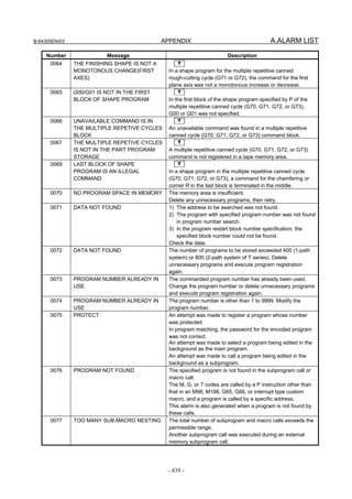
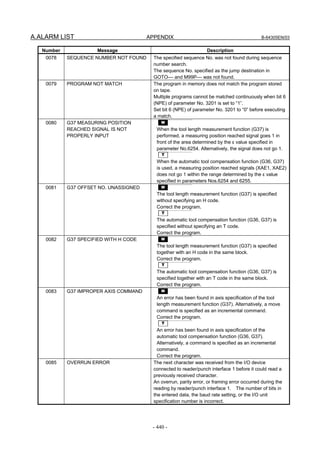
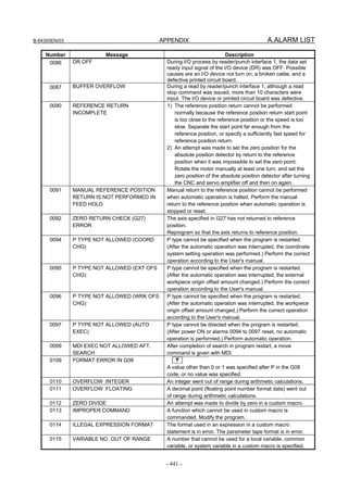
![A.ALARM LIST APPENDIX B-64305EN/03
- 442 -
Number Message Description
0116 WRITE PROTECTED VARIABLE An attempt was made in a custom macro to use on the left
side of an expression a variable that can only be used on the
right side of an expression.
0118 TOO MANY BRACKET NESTING Too many brackets “[ ]” were nested in a custom macro.
The nesting level including function brackets is 5.
0119 ARGUMENT VALUE OUT OF
RANGE
The value of an argument in a custom macro function is out of
range.
0122 TOO MANY MACRO NESTING Too many macro calls were nested in a custom macro.
0123 ILLEGAL MODE FOR
GOTO/WHILE/DO
A GOTO statement or WHILE–DO statement was found in the
main program in the MDI or DNC mode.
0124 MISSING END STATEMENT The END instruction corresponding to the DO instruction was
missing in a custom macro.
0125 MACRO STATEMENT FORMAT
ERROR
The format used in a macro statement in a custom macro is in
error.
0126 ILLEGAL LOOP NUMBER DO and END Nos. in a custom macro are in error, or exceed
the permissible range (valid range: 1 to 3).
0127 DUPLICATE NC,MACRO
STATEMENT
An NC statement and macro statement were specified in the
same block.
0128 ILLEGAL MACRO SEQUENCE
NUMBER
The specified sequence No. could not be found for sequence
number search.
The sequence No. specified as the jump destination in
GOTO-- and M99P-- could not be found.
0129 USE 'G' AS ARGUMENT G is used as an argument in a custom macro call. G cannot
be used as an argument.
0130 NC AND PMC AXIS ARE
CONFLICTED
The NC command and the PMC axis control command were
conflicted. Modify the program or ladder.
0136 SPOS AXIS - OTHER AXIS SAME
TIME
T
The M code for spindle positioning and an axis address not for
a spindle positioning axis were specified simultaneously.
Alternatively, the axis addresses of a spindle positioning axis
and non-spindle positioning axis were specified
simultaneously in the spindle positioning mode.
0137 M-CODE & MOVE CMD IN SAME
BLK.
T
The M code for spindle positioning and the axis address of a
spindle positioning axis were specified simultaneously.
0139 CANNOT CHANGE PMC CONTROL
AXIS
The PMC axis was selected for the axis for which the PMC
axis is being controlled.
0140 PROGRAM NUMBER ALREADY IN
USE
In the background, an attempt was made to select or delete
the program being selected in the foreground. Perform the
correct operation for the background edition.
0142 ILLEGAL SCALE RATE M
The scaling rate is 0 times or 10000 times or more.
Modify the setting of the scaling rate. (G51P_ … or
G51I_J_K_ … or parameter No. 5411 or 5421)
0143 COMMAND DATA OVERFLOW An overflow occurred in the storage length of the CNC internal
data. This alarm is also generated when the result of internal
calculation of scaling (M series), coordinate rotation (M
series), and cylindrical interpolation overflows the data
storage. It also is generated during input of the manual
intervention amount.
0144 ILLEGAL PLANE SELECTED M
The coordinate rotation plane and arc or cutter compensation
plane must be the same. Modify the program.](https://image.slidesharecdn.com/fanuc0imaintenancemanual-140802043306-phpapp01/85/Fanuc-0i-maintenance-manual-CNC-milling-machine-460-320.jpg)
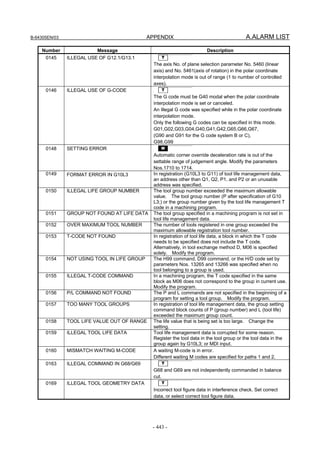
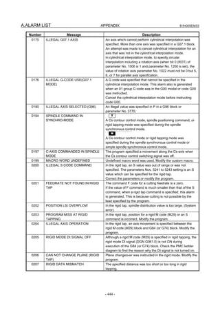
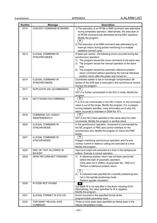
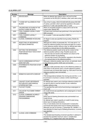
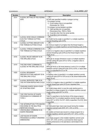
![B-64305EN/03 APPENDIX A.ALARM LIST
- 451 -
Number Message Description
0456 ILLEGAL PARAMETER IN
GRINDING
Parameters related to grinding canned cycles are incorrectly
set. Probable causes are given below.
1) The axis number of the grinding axis is incorrectly set
(parameters Nos. 5176 to 5179).
M
2) The axis number of the dressing axis is incorrectly set
(parameters Nos. 5180 to 5183).
3) The axis numbers of the cut axis, grinding axis, and
dressing axis (only for the M series) overlap.
0601 ILLEGAL AXIS OPERATION FOR
SERVO MOTOR SPINDLE
A move command is executer for the spindle controlled with
the servomotor. Modify the program.
0602 ILLEGAL AXIS OPERATION FOR
LIVE TOOL AXIS
The spindle controlled with the serve motor is not selected
correctly.
1001 AXIS CONTROL MODE ILLEGAL The axis control mode is illegal.
1013 ILLEGAL POS. OF PROGRAM NO. Address O or N is specified where it must not (After the macro
statement etc.).
1014 ILLEGAL FORMAT OF PROGRAM
NO.
Address O or N is not followed by a number.
1016 EOB NOT FOUND EOB (End of Block) code is missing at the end of a program
input in the MDI mode.
1077 PROGRAM IN USE An attempt was made in the foreground to execute a program
being edited in the background.
The currently edited program cannot be executed, so end
editing and restart program execution.
1079 PROGRAM FILE NOT FOUND The program of the specified file No. is not registered in an
external device. (external device subprogram call)
1080 DUPLICATE DEVICE SUB
PROGRAM CALL
Another external device subprogram call was made from a
subprogram after the subprogram called by the external
device subprogram call.
1081 EXT DEVICE SUB PROGRAM CALL
MODE ERROR
The external device subprogram call is not possible in this
mode.
1091 DUPLICATE SUB-CALL WORD More than one subprogram call instruction was specified in
the same block.
1092 DUPLICATE MACRO-CALL WORD More than one macro call instruction was specified in the
same block.
1093 DUPLICATE NC-WORD & M99 An address other than O, N, P or L was specified in the same
block as M99 during the macro modal call state.
1095 TOO MANY TYPE-2 ARGUMENT More than ten sets of I, J and K arguments were specified in
the type–II arguments (A, B, C, I, J, K, I, J, K, ...) for custom
macros.
1096 ILLEGAL VARIABLE NAME An illegal variable name was specified. A code that cannot be
specified as a variable name was specified. The command of
[#_OFSxx] does not match the type (A or C) of tool
compensation memory in current use.
1097 TOO LONG VARIABLE NAME The specified variable name is too long.
1098 NO VARIABLE NAME The specified variable name cannot be used as it is not
registered.
1099 ILLLEGAL SUFFIX [ ] A suffix was not specified to a variable name that required a
suffix enclosed by [ ].
A suffix was specified to a variable name that did not require a
suffix enclosed by [ ].
The value enclosed by the specified [ ] was out of range.
1100 CANCEL WITHOUT MODAL CALL Call mode cancel (G67) was specified even though macro
continuous–state call mode (G66) was not in effect.](https://image.slidesharecdn.com/fanuc0imaintenancemanual-140802043306-phpapp01/85/Fanuc-0i-maintenance-manual-CNC-milling-machine-469-320.jpg)
![A.ALARM LIST APPENDIX B-64305EN/03
- 452 -
Number Message Description
1101 ILLEGAL CNC STATEMENT IRT. An interrupt was made in a state where a custom macro
interrupt containing a move instruction could not be executed.
1115 READ PROTECTED VARIABLE An attempt was made in a custom macro to use on the right
side of an expression a variable that can only be used on the
left side of an expression.
1120 ILLEGAL ARGUMENT FORMAT The specified argument in the argument function (ATAN,
POW) is in error.
1124 MISSING DO STATEMENT The DO instruction corresponding to the END instruction was
missing in a custom macro.
1125 ILLEGAL EXPRESSION FORMAT The description of the expression in a custom macro
statement contains an error.
A parameter program format error.
The screen displayed to enter periodic maintenance data or
item selection menu (machine) data does not match the data
type.
1128 SEQUENCE NUMBER OUT OF
RANGE
The jump destination sequence No. in a custom macro
statement GOTO instruction was out of range (valid range: 1
to 99999).
1131 MISSING OPEN BRACKET The number of left brackets ([) is less than the number of right
brackets (]) in a custom macro statement.
1132 MISSING CLOSE BRACKET The number of right brackets (]) is less than the number of left
brackets ([) in a custom macro statement.
1133 MISSING '=' An equal sign (=) is missing in the arithmetic calculation
instruction in a custom macro statement.
1134 MISSING ',' A delimiter (,) is missing in a custom macro statement.
1137 IF STATEMENT FORMAT ERROR The format used in the IF statement in a custom macro is in
error.
1138 WHILE STATEMENT FORMAT
ERROR
The format used in the WHILE statement in a custom macro is
in error.
1139 SETVN STATEMENT FORMAT
ERROR
The format used in the SETVN statement in a custom macro
is in error.
1141 ILLEGAL CHARACTER IN VAR.
NAME
The SETVN statement in a custom macro contacts a
character that cannot be used in a variable name.
1142 TOO LONG V-NAME (SETVN) The variable name used in a SETVN statement in a custom
macro exceeds 8 characters.
1143 BPRNT/DPRNT STATEMENT
FORMAT ERROR
The format used in the BPRINT statement or DPRINT
statement is in error.
1144 G10 FORMAT ERROR Data input for the L No. of G10 or the corresponding function
is not enabled.
Data setting address P or R is not specified.
An address not relating to the data setting is specified. Which
address to specify varies according to the L No.
The sign, decimal point or range of the specified address are
in error.
1160 COMMAND DATA OVERFLOW An overflow occurred in the position data within the CNC.
This alarm is also generated if the target position of a
command exceeds the maximum stroke as a result of
calculation such as coordinate conversion, offset, or
introduction of a manual intervention amount.
1180 ALL PARALLEL AXES IN PARKING T
All of the axis specified for automatic operation are parked.
1196 ILLEGAL DRILLING AXIS
SELECTED
An illegal axis was specified for drilling in a canned cycle for
drilling.
In the G code command block in a canned cycle, a Z point is
not specified for the drilling axis.](https://image.slidesharecdn.com/fanuc0imaintenancemanual-140802043306-phpapp01/85/Fanuc-0i-maintenance-manual-CNC-milling-machine-470-320.jpg)
![B-64305EN/03 APPENDIX A.ALARM LIST
- 455 -
Number Message Description
1567 INDEX TABLE AXIS DUPLICATE
AXIS COMMAND
M
Index table indexing was specified during axis movement or
on an axis for which the index table indexing sequence was
not completed.
1590 TH ERROR A TH error was detected during reading from an input device.
The read code that caused the TH error and how many
statements it is from the block can be verified in the
diagnostics screen.
1591 TV ERROR An error was detected during the single–block TV error.
The TV check can be suppressed by setting bit 0 (TVC) of
parameter No. 0000 to “0”.
1592 END OF RECORD The EOR (End of Record) code is specified in the middle of a
block.
This alarm is also generated when the percentage at the end
of the NC program is read.
For the program restart function, this alarm is generated if a
specified block is not found.
1593 EGB PARAMETER SETTING
ERROR
M
Error in setting a parameter related to the EGB
1) The setting of SYN, bit 0 of parameter No. 2011, is not
correct.
2) The slave axis specified with G81 is not set as a rotation
axis. (ROT, bit 0 of parameter No. 1006)
3) Number of pulses per rotation (Parameter (No. 7772 or No.
7773) is not set.)
1594 EGB FORMAT ERROR M
Error in the format of the block of an EGB command
1) T (number of teeth) is not specified in the G81 block.
2) In the G81 block, the data specified for one of T, L, P, and
Q is out of its valid range.
3) n the G81 block, only one of P and Q is specified.
1595 ILL-COMMAND IN EGB MODE M
During synchronization with the EGB, a command that must
not be issued is issued.
1) Slave axis command using G27, G28, G29, G30, G33,
G53, etc.
2) Inch/metric conversion command using G20, G21, etc.
1596 EGB OVERFLOW M
An overflow occurred in the calculation of the synchronization
coefficient.
1805 ILLEGAL COMMAND [I/O Device]
An attempt was made to specify an illegal command during
I/O processing on an I/O device.
[G30 Reference Position Return]
The address P numbers for specifying the 2nd, 3rd, and 4th
reference position returns are not 2, 3, and 4.
[Single Rotation Dwell]
The specified spindle rotation is “0” when single rotation
dwell is specified.
1806 DEVICE TYPE MISS MATCH An operation not possible on the I/O device that is currently
selected in the setting was specified.
This alarm is also generated when file rewind is instructed
even though the I/O device is not a FANUC Cassette.
1807 PARAMETER SETTING ERROR An illegal I/O interface is specified.
The external I/O device and baud rate, stop bit and protocol
selection settings are erroneous.](https://image.slidesharecdn.com/fanuc0imaintenancemanual-140802043306-phpapp01/85/Fanuc-0i-maintenance-manual-CNC-milling-machine-473-320.jpg)
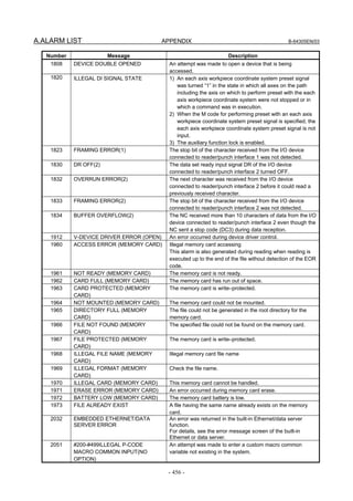
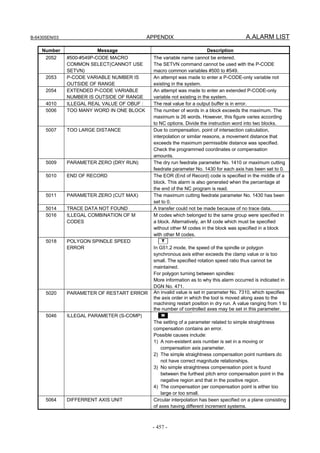
![A.ALARM LIST APPENDIX B-64305EN/03
- 458 -
Number Message Description
5065 DIFFERRENT AXIS UNIT(PMC
AXIS)
Axes having different increment systems have been specified
in the same DI/DO group for PMC axis control. Modify the
setting of parameter No. 8010.
5073 NO DECIMAL POINT No decimal point has been specified for an address requiring
a decimal point.
5074 ADDRESS DUPLICATION ERROR The same address has been specified two or more times in a
single block. Alternatively, two or more G codes in the same
group have been specified in a single block.
5110 IMPROPER G-CODE (AICC MODE) An unspecifiable G code was specified in the advanced
preview control, AI advanced preview control, or AI contour
control mode.
5131 NC COMMAND IS NOT
COMPATIBLE
T
The PMC axis control and polar coordinate interpolation were
specified simultaneously.
5195 DIRECTION CAN NOT BE JUDGED T
Measurement is invalid in the tool compensation
measurement value direct input B function.
[For 1-contact input]
1) The recorded pulse direction is not constant.
For example, the stopped state may be set during offset
write mode, the servo off state may be entered, or the
direction may vary.
2) The tool is moving along the two axes (X-axis and
Y-axis).
[For movement direction judgment in 4-contact input]
1) The recorded pulse direction is not constant.
For example, the stopped state may be set during offset
write mode, the servo off state may be entered, or the
direction may vary.
2) The tool is moving along the two axes (X-axis and
Z-axis).
3) The direction indicated by the tool compensation write
signal does not match the movement direction of the
axis.
5220 REFERENCE POINT ADJUSTMENT
MODE
In case of distance coded linear scale I/F, the reference point
auto setting bit 2 of parameter No.1819 is set to "1". Move the
machine to reference position by manual operation and
execute manual reference return.
5257 G41/G42 NOT ALLOWED IN MDI
MODE
Tool radius/tool nose radius compensation was specified in
MDI mode. (Depending on the setting of the bit 4 (MCR) of
parameter No. 5008)
5303 TOUCH PANEL ERROR The touch panel is not connected correctly, or the touch panel
cannot be initialized when the power is turned on. Correct
the cause then turn on the power again.](https://image.slidesharecdn.com/fanuc0imaintenancemanual-140802043306-phpapp01/85/Fanuc-0i-maintenance-manual-CNC-milling-machine-476-320.jpg)
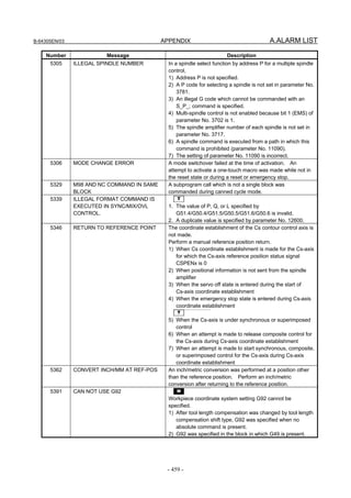
![B-64305EN/03 APPENDIX A.ALARM LIST
- 463 -
Number Message Description
SV0417 ILL DGTL SERVO PARAMETER A digital serve parameter setting is incorrect.
[When bit 4 of diagnosis information No. 203 is 1.]
An illegal parameter was detected by the servo software.
Identify the cause with reference to diagnosis information
No. 352.
[When bit 4 of diagnosis information No. 203 is 0.]
The CNC software detected an illegal parameter.
Probable causes are given below (see diagnosis
information No. 280).
1) The value specified in parameter No. 2020 as the
motor model falls outside the specified range.
2) The motor rotation direction in parameter No. 2022 is
not set to a correct value (111 or -111).
3) The speed feedback pulse count per motor rotation in
parameter No. 2023 is set to a negative or other
incorrect value.
4) The position feedback pulse count per motor rotation in
parameter No. 2024 is set to a negative or other
incorrect value.
SV0420 SYNC TORQUE EXCESS In feed axis control , for synchronization, the difference
value of torque between a master and slave axes
exceeded the parameter (No. 2031) setting value.
This alarm occurs for a master axis.
SV0421 EXCESS ERROR(SEMI-FULL) The difference between the feedback from the semi and full
sides exceeded the setting of parameter No.2118.
SV0422 EXCESS VELOCITY IN TORQUE In torque control, the commanded permissible velocity was
exceeded.
SV0423 EXCESS ERROR IN TORQUE In torque control, the total permissible move value specified
as a parameter was exceeded.
SV0430 SV MOTOR OVERHEAT The servo motor has overheated.
SV0431 CNV. OVERLOAD Power Supply (PS) : Overheat
Servo Amplifier : Overheat
SV0432 CNV. LOW VOLT CONTROL Power Supply (PS) : The control power supply voltage has
dropped.
Servo Amplifier : The control power supply voltage has
dropped.
SV0433 CNV. LOW VOLT DC LINK Power Supply (PS) : Low DC link voltage
Servo Amplifier : Low DC link voltage
SV0434 INV. LOW VOLT CONTROL Servo Amplifier : Low control power voltage
SV0435 INV. LOW VOLT DC LINK Servo Amplifier : Low DC link voltage
SV0436 SOFTTHERMAL(OVC) The digital servo software detected a software thermal
(OVC).
SV0437 CNV. OVERCURRENT POWER Power Supply (PS) : Overcurrent on input circuit section.
SV0438 INV. ABNORMAL CURRENT Servo Amplifier : Motor overcurrent
SV0439 CNV. OVER VOLT DC LINK Power Supply (PS) : The DC link voltage is too high.
Servo Amplifier : The DC link voltage is too high.
SV0440 CNV. EX DECELERATION POW. Power Supply (PS) : Excessive generative discharge
Servo Amplifier : Excessive generative discharge, or
abnormal error in generative power
circuit
SV0441 ABNORMAL CURRENT OFFSET The digital servo software detected an abnormality in the
motor current detection circuit.
SV0442 CNV. CHARGE FAILURE Power Supply (PS) : The spare charge circuit for the DC
link is abnormal.
SV0443 CNV. COOLING FAN FAILURE Power Supply (PS) : Internal cooling fan failure.
Servo Amplifier : Internal cooling fan failure.](https://image.slidesharecdn.com/fanuc0imaintenancemanual-140802043306-phpapp01/85/Fanuc-0i-maintenance-manual-CNC-milling-machine-481-320.jpg)
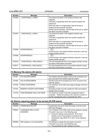
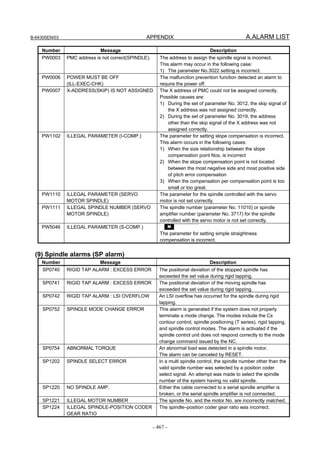
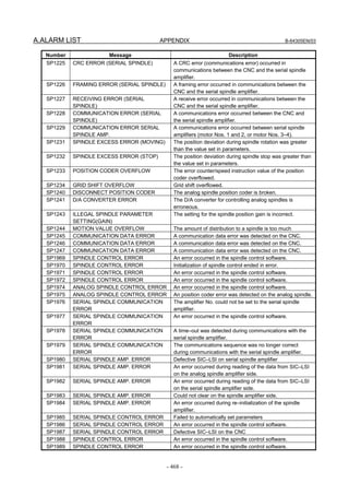
![B-64305EN/03 APPENDIX A.ALARM LIST
- 471 -
Number Message Description
DS0059 SPECIFIED NUMBER NOT FOUND [External data I/O]
The No. specified for a program No. or sequence No.
search could not be found.
There was an I/O request issued for offset (tool data), but
either no tool numbers have been input since power ON
or there is no data for the entered tool No.
[External workpiece No. search]
The program corresponding to the specified workpiece
No. could not be found.
DS0131 TOO MANY MESSAGE An attempt was made to display an external operator
message or external alarm message, but five or more
displays were required simultaneously.
DS0132 MESSAGE NUMBER NOT FOUND An attempt to cancel an external operator message or
external alarm message failed because the specified
message number was not found.
DS0133 TOO LARGE NUMBER A value other than 0 to 4095 was specified as the external
operator message or the external alarm message number.
DS0300 APC ALARM: NEED REF RETURN A setting to zero position for the absolute position detector
(association with reference position and the counter value
of the absolute position detector) is required. Perform the
return to the reference position.
This alarm may occur with other alarms simultaneously.
In this case, other alarms must be handled first.
DS0306 APC ALARM: BATTERY VOLTAGE 0 The battery voltage of the absolute position detector has
dropped to a level at which data can no longer be held. Or,
the power was supplied to the Pulsecoder for the first time.
If this problem recurs after the power is turned off and then
back on, the battery or cable may be defective. Replace
the battery with the machine turned on.
DS0307 APC ALARM: BATTERY LOW 1 The battery voltage of the absolute position detector has
dropped to a level at which a replacement is required.
Replace the battery with the machine turned on.
DS0308 APC ALARM: BATTERY LOW 2 The battery voltage of the absolute position detector
dropped to a level at which a replacement was required in
the past. (including during power off)
Replace the battery with the machine turned on.
DS0309 APC ALARM: REF RETURN
IMPOSSIBLE
An attempt was made to set the zero point for the absolute
position detector by MDI operation when it was impossible
to set the zero point.
Rotate the motor manually at least one turn, and set the
zero position of the absolute position detector after turning
the CNC and servo amplifier off and then on again.
DS0405 ZERO RETURN END NOT ON REF The axis specified in automatic zero return was not at the
correct zero point when positioning was completed.
Perform zero return from a point whose distance from the
zero return start position to the zero point is 2 or more
revolutions of the motor.
Other probable causes are:
- The positional deviation after triggering the deceleration
dog is less than 128.
- Insufficient voltage or malfunctioning Pulsecoder.
DS1120 UNASSIGNED ADDRESS (HIGH) The upper 4 bits (EIA4 to EIA7) of an external data I/O
interface address signal are set to an undefined address
(high bits).](https://image.slidesharecdn.com/fanuc0imaintenancemanual-140802043306-phpapp01/85/Fanuc-0i-maintenance-manual-CNC-milling-machine-489-320.jpg)
![A.ALARM LIST APPENDIX B-64305EN/03
- 472 -
Number Message Description
DS1121 UNASSIGNED ADDRESS (LOW) The lower 4 bits (EIA0 to EIA3) of an external data I/O
interface address signal are set to an undefined address
(low bits).
DS1124 OUTPUT REQUEST ERROR OUTPUT REQUEST ERROR An output request was
issued during external data output, or an output request
was issued for an address that has no output data.
DS1128 DI.EIDLL OUT OF RANGE The numerical value input by external data input signals
ED0 to ED31 has exceeded the permissible range.
DS1130 SEARCH REQUEST NOT ACCEPTED No requests can be accepted for a program No. or a
sequence No. search as the system is not in the memory
mode or the reset state.
DS1131 EXT-DATA ERROR (OTHER) [External Data I/O]
An attempt was made to input tool data for tool offset by
a tool No. during loading by the G10 code.
DS1150 A/D CONVERT ALARM A/D converter malfunction
DS1184 PARAMETER ERROR IN TORQUE An invalid parameter was set for torque control.
The torque constant parameter is set to “0”.
DS1448 ILLEGAL PARAMETER (D.C.S.) The setting value of parameter for reference marks is
satisfied the following any conditions.
1) A setting is made to use the absolute position detector
(bit 5 (APC) of parameter No. 1815 is 1).
2) Either parameter 1821 (mark-1 interval) or parameter
1882 (mark-2 interval) is set to 0.
3) Parameters 1821 and 1882 have identical settings.
4) The difference between the settings made for
parameters 1821 and 1882 is greater than or equal to
twice either setting.
5) The setting value of parameters 1883 and 1884 are
over the valid data range.
DS1449 REFERENCE MARK ARE DIFFERENT
FROM PARAMETER
In case of distance coded linear scale I/F, the actual
interval of reference marks is different from parameter
(No.1821,1882) setting value.
DS1450 ZERO RETURN NOT FINISHED When bit 0 (ZRN) of parameter No. 1005 is 0, if a manual
reference position return has never been performed after
power-up, the 1st reference position return (07h) is
specified.
DS1451 IMPROPER PMC AXIS COMMAND The PMC axes cannot be controlled in this state.
DS1512 EXCESS VELOCITY T
The feedrate of the linear axis during polar coordinate
interpolation exceeded the maximum cutting feedrate.
DS1933 NEED REF RETURN(SYNC:MIX:OVL) T
The relation between a machine coordinate of an axis in
synchronization, composite, or superimposed control, and
the absolute, or relative coordinate was displaced.
Perform the manual return to the reference position.
DS2003 ILLEGAL PARAMETER SETTING FOR
LIVE TOOL AXIS (PMC AX-CTRL)
The spindle controlled with the servo motor is set as a
PMC-controlled axis.
DS2005 NOW GAIN TUNING Automatic operation cannot be started during automatic
speed gain adjustment. Start automatic operation after
confirming the completion of automatic adjustment.
DS5340 PARAMETER CHECK SUM ERROR The parameter check sum does not match the reference
check sum because of a change in the parameters.
Restore the parameters or set the reference check sum
again.](https://image.slidesharecdn.com/fanuc0imaintenancemanual-140802043306-phpapp01/85/Fanuc-0i-maintenance-manual-CNC-milling-machine-490-320.jpg)
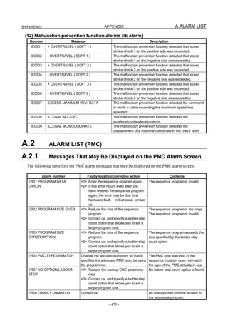
![A.ALARM LIST APPENDIX B-64305EN/03
- 474 -
Alarm number Faulty location/corrective action Contents
ER09 PMC LABEL CHECK
ERROR. PLEASE TURN ON
POWER AGAIN WITH
PRESSING 'O'&'Z'. (CLEAR
PMC SRAM)
<1> Turn on the power of the CNC again,
by holding down the 'O' and 'Z' keys
at the same time.
<2> Replace the backup batteries.
The nonvolatile memory of the PMC
system needs to be initialized in
such cases as when you have
changed the PMC model.
ER17 PROGRAM PARITY <1> Enter the sequence program again.
<2> If this error recurs even after you
have entered the sequence program
again, the error may be due to a
hardware fault. In that case, contact
us.
The parity of the sequence program
is invalid.
ER18 PROGRAM DATA
ERROR BY I/O
Enter the sequence program again. An interrupt was specified while the
sequence program was being read.
ER19 LADDER DATA ERROR Display the LADDER DIAGRAM EDITOR
screen again, and terminate the editing
operation by pressing the [EXIT] soft key.
A function key was pressed during
the editing of the ladder program,
causing a switch to the CNC screen.
ER22 NO PROGRAM Enter the sequence program again. The sequence program is empty.
ER27 LADDER FUNC. PRM IS
OUT OF RANGE
Correct the sequence program; change
the parameter number specified in a
functional instruction to a value that is
within the allowable range.
An out-of-range parameter number
is specified in the TMR, TMRB,
CTR, CTRB, DIFU, or DIFD
functional instruction.
ER28 NO OPTION(I/O LINK
CHx)
Contact us; specify the I/O Link point count
expansion option for the indicated channel.
The I/O Link point count expansion
option is not specified for CHx.
ER31 NO OPTION
(EXTENDED PMC LADDER
INSTRUCTION FUNCTION)
Change the sequence program so that it
specifies the adequate PMC model by
using the programmer.
An attempt was made to execute a
ladder program including an
extended ladder diagram.
Alternatively, the model set in the
sequence program does not match
the actual model.
ER32 NO I/O DEVICE <1> Check whether the power of each I/O
device is on.
<2> Check whether the power of each I/O
device has been turned on before the
CNC.
<3> Check cable connections.
None of the I/O devices, such as the
I/O Link, connection unit, and Power
Mate, is connected.
ER33 I/O LINK ERROR
or
ER33 I/O LINK ERROR(CHn)
Contact us; replace the faulty hardware. The LSI for the I/O Link is faulty.
ER34 I/O LINK ERROR(xx)
or
ER34 I/O LINK ERROR(CHn xx)
<1> Check the cable connections to the
devices of group xx.
<2> Check whether the power of each I/O
device has been turned on before the
CNC.
<3> Replace any device of group xx in
which the PMC control module is
embedded.
An I/O device communication error
occurred on the slave side of group
xx.
ER35 TOO MUCH OUTPUT
DATA IN GROUP(xx)
or
ER35 TOO MUCH OUTPUT
DATA IN GROUP(CHn xx)
Reduce the output data count of group xx. The output data count of I/O Link
group xx exceeds the upper limit (33
bytes). The superfluous data is
regarded as invalid.
ER36 TOO MUCH INPUT DATA
IN GROUP(xx)
or
ER36 TOO MUCH INPUT DATA
IN GROUP(CHn xx)
Reduce the input data count of group xx. The input data count of I/O Link
group xx exceeds the upper limit (33
bytes). The superfluous data is
regarded as invalid.](https://image.slidesharecdn.com/fanuc0imaintenancemanual-140802043306-phpapp01/85/Fanuc-0i-maintenance-manual-CNC-milling-machine-492-320.jpg)
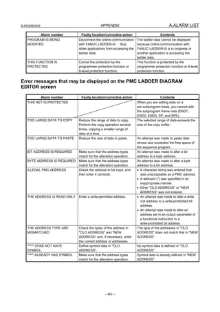
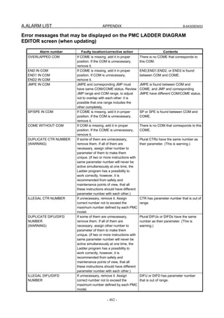
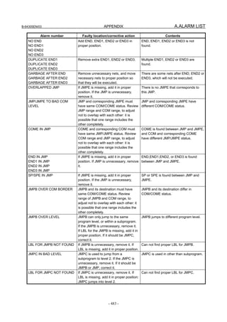
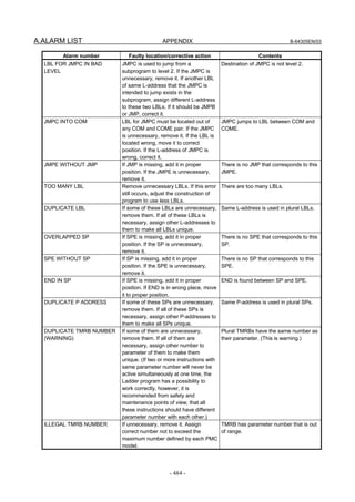
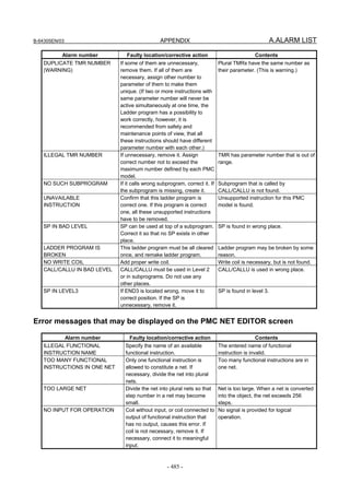
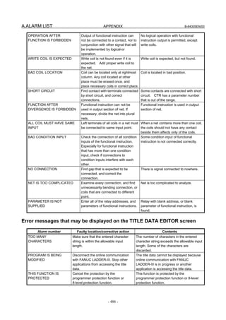
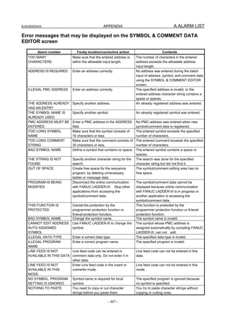
![A.ALARM LIST APPENDIX B-64305EN/03
- 488 -
Alarm number Faulty location/corrective action Contents
TOO LARGE DATA TO
PASTE
Shorten the character string to copy or
cut.
The character strings is too long to copy or
cut.
UNAVAILABLE
CHARACTERS WAS
OMITTED.
Do not copy or cut characters which can
not be used at pasted position.
The characters which can not be used at
pasted position, were omitted.
Error messages that may be displayed on the MESSAGE DATA EDITOR
screen
Alarm number Faulty location/corrective action Contents
INPUT INVALID Enter ";" in the 5th digit position in the
batch message input process.
The delimiter code - semicolon (;) - was
not entered in the batch message input
process.
ILLEGAL NUMBER Enter a four-digit number as the
message number.
The entered message number contains
any nonnumeric character, or a number
shorter than four digits was entered.
THE NUMBER IS OUT OF
RANGE
Make sure that the entered message
number is in the range between 1000
and 9999.
The entered message number is out of
the 1000-9999 range.
CLOSING "@" IS NOT FOUND When entering kana or other
Japanese characters, make sure that
they are enclosed within a pair of @
signs.
One of the @ sign pair is missing.
BAD NUMBER OF
CHARACTERS IN "@-@"
Enter a character string correctly
between a pair of @ signs.
The number of characters entered
between the pair of @ signs is not even.
ILLEGAL CHARACTER IN
"@-@"
Enter a character string correctly
between a pair of @ signs.
One or more invalid character codes
exist between the pair of @ signs.
BAD NUMBER OF
CHARACTERS FOR 2-BYTE
CODE
Enter a two-byte code correctly
between @02 and 01@.
The number of characters in the two-byte
code (characters entered between @02
and 01@) is not a multiple of four.
ILLEGAL 2-BYTE CODE Enter a two-byte code correctly
between @02 and 01@.
The two-byte code (characters entered
between @02 and 01@) contains one or
more characters other than the JIS
codes.
CLOSING CONTROL CODE
"01" IS NOT FOUND
Enter the closing control code. The two-byte code (characters entered
between @02 and 01@) lacks the
closing control code (01).
CONTROL CODE "XX" IS
REPEATED
Remove any repeated control code. The starting control code (02), closing
control code (01), and/or umlaut code
(0D) is repeated.
CLOSING "]" IS NOT FOUND Make sure that the "[" and "]" codes
are entered in pairs.
The delimiter codes for numerical data
are not entered in pairs.
BAD NUMERICAL DATA
FORMAT
Specify the numerical data correctly. The format of the numerical data is
invalid.
BAD PMC ADDRESS FOR
NUMERIAL DATA
Enter an available address. The address section of the numerical
data is invalid.
PROGRAM IS BEING
MODIFIED
Disconnect the online communication
with FANUC LADDER-III. Stop
other applications from accessing the
message data.
The message data cannot be displayed
because online communication with
FANUC LADDER-III is in progress or
another application is accessing the
message data.
THIS FUNCTION IS
PROTECTED
Cancel the protection by the
programmer protection function or
8-level protection function.
This function is protected by the
programmer protection function or 8-level
protection function.](https://image.slidesharecdn.com/fanuc0imaintenancemanual-140802043306-phpapp01/85/Fanuc-0i-maintenance-manual-CNC-milling-machine-506-320.jpg)
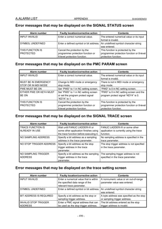
![B-64305EN/03 APPENDIX A.ALARM LIST
- 491 -
Alarm number Faulty location/corrective action Contents
INVALID SAMPLING TRIGGER
ADDRESS
Enter a PMC signal address that can
be used as the sampling trigger
address.
The bit address entered as the sampling
trigger address is invalid.
Error messages that may be displayed on the I/O diagnosis screen
Alarm number Faulty location/corrective action Contents
ENTER STRING TO SEARCH. Enter a string before starting a
search.
No search string is specified.
I/O DIAGNOSIS FUNCTION IS
NOT SUPPORTED
To use the I/O diagnosis function,
update the PMC system software.
The I/O diagnosis function cannot be
used because the PMC system software
is an older version.
INPUT INVALID Check the entered string. The entered string is invalid.
LADDER PROGRAM IS
BROKEN
Check the information displayed on
the PMC alarm screen and reload the
program.
The program is corrupted.
NO GROUP FORMAT. Use [GROUP] on the I/O diagnosis
(setting) screen.
No group display is set.
PROGRAM IS BEING
MODIFIED.
Retry after completing the function
that is using the program.
The program cannot be referenced
because it is being used by another
function.
REACHED TO THE END OF
SYMBOL DATA.
To make another search, specify a
string again.
The search has been completed until
the end of the data has been reached.
SYMBOL ORDER IS NOT
AVAILABLE.
Use the FANUC LADDER-III to
convert the program to one with an
expanded function.
The format of this program does not
allow sorting and display in symbol
order.
THE GROUP IS NOT FOUND Check the specified group. The specified group is not found.
FORCING IS PROTECTED ON
THIS PATH.
Disable the programmer protection
function.
The forced input/output function is
currently protected on the selected PMC
path.
THE STRING IS NOT FOUND Check the specified string. The specified string is not found.
A.2.4 I/O Communication Error Messages
The error messages that may appear on the I/O screen and their meanings and actions are listed below.
Error messages displayed during memory card I/O operation
Alarm number Faulty location/corrective action Contents
MEMORY CARD IS NOT
READY
Check whether a memory card is
installed.
No memory card is installed.
MEMORYCARD IS FULL Delete files to create available space. There is no available space in the
memory card.
MEMORYCARD IS WRITE
PROTECTED
Release the write protection of the
memory card.
The memory card is write-protected.
MEMORYCARD IS NOT
FORMATTED
Format the memory card in FAT16.
(It cannot be recognized if formatted
in FAT32.)
The memory card cannot be recognized.
TOO MANY FILES IN
MEMORYCARD
Delete unnecessary files to reduce
the number of files.
There are too many files.
FILE NOT FOUND On the list screen, check the file
name or file number.
The specified file cannot be found.
FILE IS READ-ONLY Check the attributes of the file. Write to the specified file is not permitted.
FILE NAME IS INVALID Specify the file name in MS-DOS
form.
The file name is illegal.](https://image.slidesharecdn.com/fanuc0imaintenancemanual-140802043306-phpapp01/85/Fanuc-0i-maintenance-manual-CNC-milling-machine-509-320.jpg)
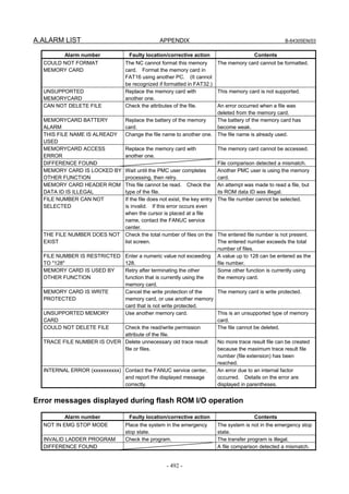
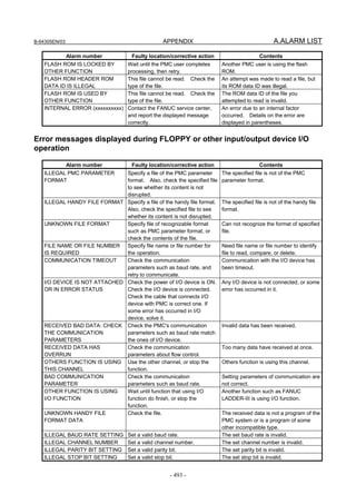
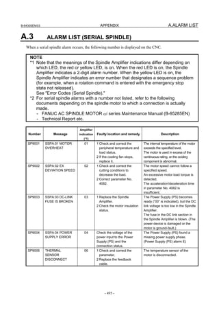
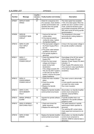
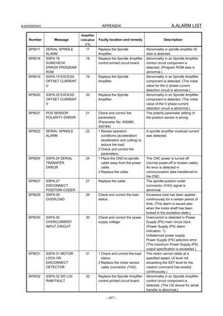
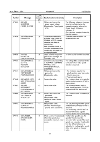
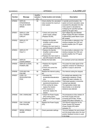
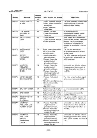
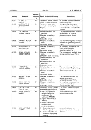
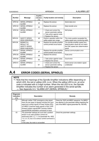
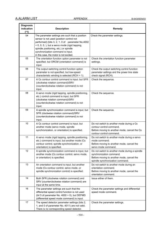
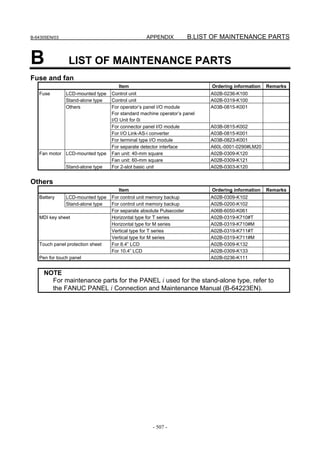
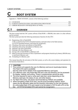
![B-64305EN/03 APPENDIX C.BOOT SYSTEM
- 509 -
C.1.1 Displaying the Power ON Sequence
(1)
(2)
(3)
(4)
(5)
(7)
(2)
(6)
Processing is stopped in the event of an
error
SELECT key → SYSTEM MONITOR
Details of display items
(1) WORK RAM test results are displayed. In the event of an error, however, the sequence is not
displayable, and LED indication is conducted without error display.
(2) BOOT ROM parity test results are displayed. During normal operation, the series and edition are
displayed. In the event of an error, processing is stopped.
(3) The ID of the DRAM MODULE installed in the CNC is displayed.
(4) The ID of the SRAM MODULE installed in the CNC is displayed.
(5) The ID of the FROM MODULE installed in the CNC is displayed.
(6) The CNC BASIC software in flash memory is checked for validity and, in the event of an error, an
error is displayed. In the event of an error, clicking the [SELECT] soft key allows you to select the
SYSTEM MONITOR screen.
(7) This message indicates that the CNC BASIC software is being transferred to flash memory to
DRAM.
C.1.2 Starting the Boot System
In ordinary system activation, the boot system automatically transfers files from Flash ROM to DRAM in
the background.
The user is not aware of this operation. However, the boot system must be operated manually, from menu
screen, when maintenance is to be carried out or when the Flash ROM does not contain a required file.
Operating procedure
(1) In system maintenance, for example, to replace a file in ROM operation
- When soft keys or MDI keys are present
Turn on the power while pressing the rightmost soft key and the soft key to the right at the same time.
Numerical keys 6 and 7 on the MDI keyboard can also be used.
RAM TEST :END
ROM TEST :END [60W3A]
DRAM ID :xxxxxxxx
SRAM ID :xxxxxxxx
FROM ID :xxxxxxxx
*** MESSAGE ***
LOADING CNC DATA-1 xxxxxx/xxxxxx
END
*** MESSAGE ***
ROM PARITY ERROR:NC BASIC. HIT SELECT.
[SELECT][ YES ][ NO ][ UP ][ DOWN ]
RAM TEST :END
ROM TEST :ERROR](https://image.slidesharecdn.com/fanuc0imaintenancemanual-140802043306-phpapp01/85/Fanuc-0i-maintenance-manual-CNC-milling-machine-527-320.jpg)
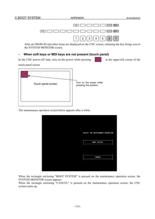
![C.BOOT SYSTEM APPENDIX B-64305EN/03
- 512 -
C.2 SCREEN CONFIGURATION AND OPERATING
PROCEDURE
When the boot system is first started, the MAIN MENU screen is displayed. This screen is described
below :
MAIN MENU screen
(1)
(2)
(3)
(4)
(5)
(6)
(7)
(8)
(9)
(10)
(1) Screen title. The series and edition of
the BOOT SYSTEM are displayed at
the right end.
(2) Function for terminating the boot
system and starting the CNC.
(3) Function for writing data to Flash
ROM.
(4) Function for writing data to Flash
ROM.
(5) Function for checking the edition of a
file in ROM.
(6) Function for deleting a file from Flash
ROM or Memory card.
(7) Function for making a backup copy of
the data stored on the Memory card.
(8) Function for backing up and restoring
the SRAM area
(9) Function for formatting a Memory card.
(10) Simple operating instructions and error
messages are displayed.
Operating procedure
- For other than the touch panel
Press the [UP] or [DOWN] soft key to select the desired function. After positioning the cursor to the
desired function, press the [SELECT] soft key. Before executing a function, for a confirmation, it maybe
need to press the [YES] or [NO] soft key.
- For the touch panel
This procedure directly presses [SELECT], [YES], [NO], [UP], and [DOWN] on the screen. For the
touch panel, [PREV] equivalent to soft key and [NEXT] equivalent to soft key are
displayed, so press these keys for operation.
Basic operation
SYSTEM MONITOR MAIN MENU 60W3 - 01
1.END
2.USER DATA LOADING
3.SYSTEM DATA LOADING
4.SYSTEM DATA CHECK
5.SYSTEM DATA DELETE
6.SYSTEM DATA SAVE
7.SRAM DATA BACKUP
8.MEMORY CARD FORMAT
*** MESSAGE ***
SELECT MENU AND HIT SELECT KEY.
[SELECT][ YES ][ NO ][ UP ][ DOWN ]
Position the cursor.
[ UP ]
[ DOWN ]
Select a function
[SELECT]
Check the selection
[ YES ]
[ NO ]
Execute the
function Select END
Return to original
state](https://image.slidesharecdn.com/fanuc0imaintenancemanual-140802043306-phpapp01/85/Fanuc-0i-maintenance-manual-CNC-milling-machine-530-320.jpg)
![B-64305EN/03 APPENDIX C.BOOT SYSTEM
- 513 -
C.2.1 USER DATA LOADING/SYSTEM DATA LOADING Screen
Description
This screen is used to read a system or user file from a Memory card into Flash ROM.
The USER DATA LOADING screen is used to load ROM data from a Memory card to flash memory.
The SYSTEM DATA LOADING screen is used to check the contents of the ROM card installed in a
Memory card and then load ROM data from the Memory card to flash memory.
Screen configuration
(1)
(2)
(3)
(4)
(5)
(1) Screen title.
(2) The size of the free space of the
Memory card is displayed.
(3) A list of files in the Memory card is
displayed.
(4) Returning to the MAIN MENU.
(5) Message
Operating procedure
(1) Position the cursor to the file to be read from the Memory card and written to Flash ROM. Then,
press the [SELECT] soft key.
- A single page can list up to ten file names.
- If the Memory card contains ten or more files, the remaining files are displayed on another
page.
To display the next page, press the soft key.
To display the previous page, press the soft key. The END option is displayed on the
last page.
(2) When you select a file from the USER DATA LOADING screen, you are prompted for
confirmation.
SYSTEM DATA LOADING
MEMORY CARD DIRECTORY (FREE[KB]: 5123)
1 D4F1_B1.MEM 1048704 2003-01-01 12:00
2 D4F1_B2.MEM 1048704 2003-01-01 12:00
3 END
*** MESSAGE ***
SELECT MENU AND HIT SELECT KEY.
[SELECT][ YES ][ NO ][ UP ][ DOWN ]
USER DATA LOADING
MEMORY CARD DIRECTORY (FREE[KB]: 5123)
1 D4F1_B1.MEM 1048704 2003-01-01 12:00
2 D4F1_B2.MEM 1048704 2003-01-01 12:00
3 END
*** MESSAGE ***
LOADING OK ? HIT YES OR NO.
[SELECT][ YES ][ NO ][ UP ][ DOWN ]](https://image.slidesharecdn.com/fanuc0imaintenancemanual-140802043306-phpapp01/85/Fanuc-0i-maintenance-manual-CNC-milling-machine-531-320.jpg)
![C.BOOT SYSTEM APPENDIX B-64305EN/03
- 514 -
(3) When you select a file from the SYSTEM DATA LOADING screen, a ROM data confirmation
screen is displayed for confirmation.
(4) To start loading, press the [YES] soft key. To cancel, press the [NO] key.
(5) When loading terminates normally, the system displays the following message. Press the [SELECT]
soft key. If an error occurs, see C.3
NOTE
1 The option parameters of the CNC are saved in the option information file
(OPRM INF). If this file is modified, the option parameters need to be certified
because the settings of the option parameter are assumed to be changed.
2 Since the option information file (OPRM INF) may be necessary when the
printed circuit board is replaced, it is recommended that this file be backed up in
advance as in SRAM data.
*** MESSAGE ***
LOADING FROM MEMORY CARD xxxxxx/xxxxxx
[SELECT][ YES ][ NO ][ UP ][ DOWN ]
*** MESSAGE ***
LOADING COMPLETE.
HIT SELECT KEY.
[SELECT][ YES ][ NO ][ UP ][ DOWN ]
SYSTEM DATA CHECK & DATA LOADING
D4F1_B1.MEM
1 D4F1 001A
2 D4F1 021A
3 D4F1 041A
4 D4F1 061A
5 D4F1 081A
6 D4F1 0A1A
7 D4F1 0C1A
8 D4F1 0E1A
*** MESSAGE ***
LOADING OK ? HIT YES OR NO.
[SELECT][ YES ][ NO ][ UP ][ DOWN ]](https://image.slidesharecdn.com/fanuc0imaintenancemanual-140802043306-phpapp01/85/Fanuc-0i-maintenance-manual-CNC-milling-machine-532-320.jpg)
![B-64305EN/03 APPENDIX C.BOOT SYSTEM
- 515 -
C.2.2 SYSTEM DATA CHECK Screen
Description
This screen is used to list files in Flash ROM or Memory card, together with the corresponding numbers
of management units in each file and the series and edition of the software.
Screen configuration
(1)
(2)
(3)
(4)
(5)
(1) Screen title.
(2) Select the FROM SYSTEM screen.
(3) Select the MEMORY CARD SYSTEM
screen.
(4) Returning to the MAIN MENU.
(5) Message
Screen configuration (FROM SYSTEM screen)
(1)
(2)
(3)
(4)
(1) Screen title.
(2) Names of files in Flash ROM The
number of management units
constituting each file appears in
parentheses to the right of the filename.
(3) Returning to the MAIN MENU.
(4) Message
SYSTEM DATA CHECK
1.FROM SYSTEM
2.MEMORY CARD SYSTEM
3.END
*** MESSAGE ***
SELECT MENU AND HIT SELECT KEY.
[SELECT][ YES ][ NO ][ UP ][ DOWN ]
SYSTEM DATA CHECK
FROM DIRECTORY
1 NC BAS-1(0008)
2 NC BAS-2(0008)
3 NC BAS-3(0008)
4 NC BAS-4(0008)
5 DGD0SRVO(0003)
6 PS0B (0006)
7 END
*** MESSAGE ***
SELECT FILE AND HIT SELECT KEY.
[SELECT][ YES ][ NO ][ UP ][ DOWN ]](https://image.slidesharecdn.com/fanuc0imaintenancemanual-140802043306-phpapp01/85/Fanuc-0i-maintenance-manual-CNC-milling-machine-533-320.jpg)
![C.BOOT SYSTEM APPENDIX B-64305EN/03
- 516 -
Screen configuration (MEMORY CARD SYSTEM screen)
(1)
(2)
(3)
(4)
(5)
(1) Screen title.
(2) The size of the free space of the
Memory card is displayed.
(3) A list of files in the Memory card is
displayed.
(4) Returning to the MAIN MENU.
(5) Message
Operating procedure
(1) Select either the FROM SYSTEM or MEMORY CARD SYSTEM screen.
(2) Select the file that you want to confirm (for example, "NC BAS-1 (0008)").
(3) For the selected file, the management unit numbers are listed, together with the series and editions of
the management units. After checking the listed data, select the [SELECT] soft key to return to the
file selection screen.
(1)
(2)
(1) Screen title.
(2) The following items are displayed for
each management unit:
- Series
- ROM number and edition
- Internal management-unit number
If a check result cannot be displayed, a
"@" is displayed.
Others (Parity information for the system file and user file)
The NC BAS-1, DGD0SRVO, and other system files in Flash ROM contain parity information in each
management unit. If the file name field or parity field on the check screen contains a non-ASC II
character or an "@", the Flash ROM may have been destroyed or a damaged file may have been read.
Re-read the data from the Memory card.
The PMC1, and other user files do not contain parity information in each management unit. A non-ASCII
character or an "@" may appear in the series/edition information. In this case, it does not indicate that the
file has been damaged.
SYSTEM DATA CHECK
MEMORY CARD DIRECTORY (FREE[KB]: 5123)
1 D4F1_B1.MEM 1048704 2003-01-01 12:00
2 D4F1_B2.MEM 1048704 2003-01-01 12:00
3 END
*** MESSAGE ***
SELECT FILE AND HIT SELECT KEY.
[SELECT][ YES ][ NO ][ UP ][ DOWN ]
SYSTEM DATA CHECK
NC BAS-1(0008)
1 D4F1 001A 0000
2 D4F1 021A 0001
3 D4F1 041A 0002
4 D4F1 061A 0003
5 D4F1 081A 0004
6 D4F1 0A1A 0005
7 D4F1 0C1A 0006
8 D4F1 0E1A 0007
*** MESSAGE ***
HIT SELECT KEY.
[SELECT][ YES ][ NO ][ UP ][ DOWN ]](https://image.slidesharecdn.com/fanuc0imaintenancemanual-140802043306-phpapp01/85/Fanuc-0i-maintenance-manual-CNC-milling-machine-534-320.jpg)
![B-64305EN/03 APPENDIX C.BOOT SYSTEM
- 517 -
C.2.3 SYSTEM DATA DELETE Screen
Description
This screen is used to delete a user file from Flash ROM or Memory card.
Screen configuration
(1)
(2)
(3)
(4)
(5)
(1) Screen title.
(2) Select the FROM SYSTEM screen.
(3) Select the MEMORY CARD SYSTEM
screen.
(4) Returning to the MAIN MENU.
(5) Message
Screen configuration (FROM SYSTEM screen)
(1)
(2)
(3)
(4)
(1) Screen title.
(2) Names of files in Flash ROM
The number of management units
constituting each file appears in
parentheses to the right of the filename.
(3) Returning to the MAIN MENU.
(4) Message
Screen configuration (MEMORY CARD SYSTEM screen)
(1)
(2)
(3)
(4)
(5)
(1) Screen title.
(2) The size of the free space of the
Memory card is displayed.
(3) A list of files in the Memory card is
displayed.
(4) Returning to the MAIN MENU.
(5) Message
SYSTEM DATA DELETE
1.FROM SYSTEM
2.MEMORY CARD SYSTEM
3.END
*** MESSAGE ***
SELECT MENU AND HIT SELECT KEY.
[SELECT][ YES ][ NO ][ UP ][ DOWN ]
SYSTEM DATA DELETE
FROM DIRECTORY
1 NC BAS-1(0008)
2 NC BAS-2(0008)
3 NC BAS-3(0008)
4 NC BAS-4(0008)
5 DGD0SRVO(0003)
6 PS0B (0006)
7 PMC1 (0001)
8 END
*** MESSAGE ***
SELECT FILE AND HIT SELECT KEY.
[SELECT][ YES ][ NO ][ UP ][ DOWN ]
SYSTEM DATA DELETE
MEMORY CARD DIRECTORY (FREE[KB]: 5123)
1 D4F1_B1.MEM 1048704 2003-01-01 12:00
2 D4F1_B2.MEM 1048704 2003-01-01 12:00
3 END
*** MESSAGE ***
SELECT FILE AND HIT SELECT KEY.
[SELECT][ YES ][ NO ][ UP ][ DOWN ]](https://image.slidesharecdn.com/fanuc0imaintenancemanual-140802043306-phpapp01/85/Fanuc-0i-maintenance-manual-CNC-milling-machine-535-320.jpg)
![C.BOOT SYSTEM APPENDIX B-64305EN/03
- 518 -
Operating procedure
(1) Select either the FROM SYSTEM or MEMORY CARD SYSTEM screen.
(2) Select the file you want to delete.
(3) The following message is displayed for confirmation.
(4) To start deleting, press the [YES] soft key. To cancel, press the [NO] key.
(5) When deleting terminates normally, the system displays the following message. Press the [SELECT]
soft key. If an error occurs, see C.3
Others (System files and user files on SYSTEM DATA DELETE screen)
The system files are protected from accidental deletion. User files, however, are not protected. Protected
system files can be overwritten from the USER DATA LOADING / SYSTEM DATA LOADING screen.
C.2.4 SYSTEM DATA SAVE Screen
Description
This screen is used to write a user file in Flash ROM to a Memory card. Only user files can be saved from
Flash ROM to a Memory card. System files cannot be saved.
Screen configuration
(1)
(2)
(3)
(4)
(1) Screen title.
(2) Names of files in Flash ROM
The number of management units
constituting each file appears in
parentheses to the right of the filename.
(3) Returning to the MAIN MENU.
(4) Message
*** MESSAGE ***
DELETE OK ? HIT YES OR NO.
[SELECT][ YES ][ NO ][ UP ][ DOWN ]
*** MESSAGE ***
EXECUTING
ADDRESS xxxx:
[SELECT][ YES ][ NO ][ UP ][ DOWN ]
*** MESSAGE ***
DELETE COMPLETE. HIT SELECT KEY.
[SELECT][ YES ][ NO ][ UP ][ DOWN ]
SYSTEM DATA SAVE
FROM DIRECTORY
1 NC BAS-1(0008)
2 NC BAS-2(0008)
3 NC BAS-3(0008)
4 NC BAS-4(0008)
5 DGD0SRVO(0003)
6 PS0B (0006)
7 PMC1 (0001)
8 END
*** MESSAGE ***
SELECT FILE AND HIT SELECT KEY.
[SELECT][ YES ][ NO ][ UP ][ DOWN ]](https://image.slidesharecdn.com/fanuc0imaintenancemanual-140802043306-phpapp01/85/Fanuc-0i-maintenance-manual-CNC-milling-machine-536-320.jpg)
![B-64305EN/03 APPENDIX C.BOOT SYSTEM
- 519 -
Operating procedure
(1) Select the file you want to save.
(2) The system displays the following confirmation message :
(3) To start saving, press the [YES] key. To cancel, press [NO].
(4) When saving terminates normally, the system displays the following message. Press the [SELECT]
key. The names of files written to the Memory card are listed. Check the file names by, for example,
making a note of the list.
Saving ATA PROG
A file whose file name is ATA PROG contains an NC program. Even if you want to save this file, you
cannot save it on this SYSTEM DATA SAVE screen, because it is saved together with SRAM data on the
SRAM DATA UTILITY screen.
Others (System files and user files on SYSTEM DATA SAVE screen)
The SYSTEM DATA SAVE function provides a safeguard against free copying of the system files.
User files, however, are not protected.
Files saved from Flash ROM to a Memory card have the following names :
Header ID in Flash ROM File name in Memory card
PMC1
PC010.5M
PC011.0M
→
→
→
PMC1.xxx
PC0105M.xxx
PC0110M.xxx
"xxx" is replaced by one of 32 numbers "000", "001", …, and "031".
For example, if you attempt to save the file "PMC1 " from Flash ROM to a Memory card, it will be
saved with a name of "PMC1.000" if no file with a name of "PMC1.000" is found on the Memory card. If,
however, that file is saved to a Memory card that already contains a file named PMC1.000, the saved file
is named PMC1.001. As files are added, the extension is incremented up to a maximum of PMC1.031.
Any no-longer used numbers in the sequence of the extension numbers are used in as sending order. If
two or more files having identical names but different extension numbers are normally saved to the
Memory card, check the file names displayed subsequently.
*** MESSAGE ***
SYSTEM DATA SAVE OK ? HIT YES OR NO.
[SELECT][ YES ][ NO ][ UP ][ DOWN ]
*** MESSAGE ***
STORE TO MEMORY CARD
[SELECT][ YES ][ NO ][ UP ][ DOWN ]
*** MESSAGE ***
FILE SAVE COMPLETE. HIT SELECT KEY.
SAVE FILE NAME : PMC1.000
[SELECT][ YES ][ NO ][ UP ][ DOWN ]](https://image.slidesharecdn.com/fanuc0imaintenancemanual-140802043306-phpapp01/85/Fanuc-0i-maintenance-manual-CNC-milling-machine-537-320.jpg)
![C.BOOT SYSTEM APPENDIX B-64305EN/03
- 520 -
C.2.5 SRAM DATA UTILITY Screen
Description
This screen is used to collectively save and restore parameters, tool compensation memories, and other
data, retained after the CNC power in SRAM is turned off, to and from a Memory card.
Automatic data backup (optional function) is available to restore data backed up in the FROM in the
CNC.
Screen configuration
(1)
(2)
(3)
(4)
(5)
(6)
(1) Screen title.
(2) Menu
(3) Returning to the MAIN MENU.
(4) The SRAM file size is displayed.
(Displayed after a processing option is
selected.)
(5) The name of the file currently being
saved or loaded is displayed. (Displayed
after a processing option is selected.)
(6) Message
Operating procedure (Backing up data)
(1) Select "1.SRAM BACKUP" The following confirmation message is displayed. To start backup,
press the [YES] soft key.
(2) If the data cannot be saved entirely onto a single Memory card, a message such as that shown below
is displayed. With the power still on, insert the second Memory card and press the [YES] key. Press
the [NO] key to cancel saving.
(3) In this way, you can divide SRAM data onto a maximum of 999 Memory card for backup.
SRAM DATA UTILITY
1.SRAM BACKUP ( CNC -> MEMORY CARD )
2.SRAM RESTORE ( MEMORY CARD -> CNC )
3.AUTO BKUP RESTORE ( FROM -> CNC )
4.END
SRAM + ATA PROG FILE : (4MB)
SRAM_BAK.001
*** MESSAGE ***
SET MEMORY CARD NO.001
ARE YOU SURE ? HIT YES OR NO.
[SELECT][ YES ][ NO ][ UP ][ DOWN ]
*** MESSAGE ***
SELECT MENU AND HIT SELECT KEY.
[SELECT][ YES ][ NO ][ UP ][ DOWN ]
*** MESSAGE ***
SET MEMORY CARD NO.002
ARE YOU SURE ? HIT YES OR NO.
[SELECT][ YES ][ NO ][ UP ][ DOWN ]](https://image.slidesharecdn.com/fanuc0imaintenancemanual-140802043306-phpapp01/85/Fanuc-0i-maintenance-manual-CNC-milling-machine-538-320.jpg)
![B-64305EN/03 APPENDIX C.BOOT SYSTEM
- 521 -
(4) Upon the termination of backup, the system displays the following message. Press the [SELECT]
soft key.
Operating procedure (Restoring the data)
(1) Select "2.RESTORE SRAM" The following confirmation message is displayed. To start restoration,
press the [YES] soft key.
(2) A message such as that shown below is displayed. Insert the first Memory card containing
SRAMBACK.001 and press the [YES] key. Press the [NO] key to cancel restoration.
(3) If another Memory card is required, a message such as that shown below is displayed. With the
power still on, insert the second Memory card and press the [YES] key. Press the [NO] key to cancel
restoration.
(4) Replace the second card with another, if required. Repeat this step until backing up all data.
(5) Upon the termination of restoration, the system displays the following message. Press the [SELECT]
soft key.
CAUTION
1 Backup files will be created with a file name of SRAMBAK.xxx, where xxx is
replaced with a number between 001 and 999 sequentially.
On the first Memory card, a backup file is created with a name of SRAMBAK.001.
If all data is not contained on the single card, a backup file containing the excess
data is created with a name of SRAMBAK.002 on the second Memory card.
In this way, you can divide data onto a maximum of 999 Memory card for saving.
2 Check that the Memory card used for backup does not contain a file with a name
of SRAMBAK.xxx before performing a BACKUP operation. You can check a list
of file names on a Memory card by using the SYSTEM DATA LOADING function.
3 The Memory card used for backup needs to be formatted in FAT16.
*** MESSAGE ***
SRAM BACKUP COMPLETE. HIT SELECT KEY.
[SELECT][ YES ][ NO ][ UP ][ DOWN ]
*** MESSAGE ***
SET MEMORY CARD INCLUDING SRAM_BAK.001
ARE YOU SURE ? HIT YES OR NO.
[SELECT][ YES ][ NO ][ UP ][ DOWN ]
*** MESSAGE ***
SET MEMORY CARD INCLUDING SRAM_BAK.002
ARE YOU SURE ? HIT YES OR NO.
[SELECT][ YES ][ NO ][ UP ][ DOWN ]
*** MESSAGE ***
SRAM RESTORE COMPLETE. HIT SELECT KEY.
[SELECT][ YES ][ NO ][ UP ][ DOWN ]](https://image.slidesharecdn.com/fanuc0imaintenancemanual-140802043306-phpapp01/85/Fanuc-0i-maintenance-manual-CNC-milling-machine-539-320.jpg)
![C.BOOT SYSTEM APPENDIX B-64305EN/03
- 522 -
Operating procedure (Restoring backup data using automatic data backup
(option))
(1) Select "3.AUTO BKUP RESTORE." The following menu is displayed.
(When the FROM contains no backup data, “1. END” is displayed.)
(2) Select data from the above menu and execute restoration.
Selecting END displays the SRAM DATA UTILITY screen again.
(3) Upon the termination of restoration, the system displays the following message.
Press the [SELECT] key to terminate operation. (The MAIN MENU screen of the boot system is
displayed again.)
C.2.6 MEMORY CARD FORMAT Screen
Description
This function is used to format a Memory card. Memory cards must be formatted before they can be used
for the first time or before they can be re-used after their data has been destroyed or lost because of, for
example, battery failure.
Operating procedure
(1) From the MAIN MENU screen, select "8.MEMORY CARD FORMAT."
(2) The system displays the following confirmation message. Press the [YES] key.
(3) The system displays the following message asking whether to delete all data on the Memory card.
To format the Memory card, press the [YES] key.
*** MESSAGE ***
MEMORY CARD FORMAT OK ? HIT YES OR NO.
[SELECT][ YES ][ NO ][ UP ][ DOWN ]
*** MESSAGE ***
MEMORY CARD FORMAT OK ? HIT YES OR NO.
ALL DATA IN THE MEMORY CARD IS LOST.
[SELECT][ YES ][ NO ][ UP ][ DOWN ]
*** MESSAGE ***
RESTORE COMPLETE. HIT SELECT KEY.
[SELECT][ YES ][ NO ][ UP ][ DOWN ]
AUTO BACKUP DATA RESTORE
1. BACKUP DATA1 yyyy/mm/dd **:**:**
2. BACKUP DATA2 yyyy/mm/dd **:**:**
3. BACKUP DATA3 yyyy/mm/dd **:**:**
4. END](https://image.slidesharecdn.com/fanuc0imaintenancemanual-140802043306-phpapp01/85/Fanuc-0i-maintenance-manual-CNC-milling-machine-540-320.jpg)
![B-64305EN/03 APPENDIX C.BOOT SYSTEM
- 523 -
(4) The system displays the following message during formatting :
(5) When a card has been formatted normally, the system display the following message. Press the
[SELECT] soft key.
C.2.7 LOAD BASIC SYSTEM
Description
The function is used to terminate the boot system and activate the CNC.
Operating procedure
From the MAIN MENU screen, select "1. END." The system displays the "ARE YOU SURE? HIT YES
OR NO" message. To terminate the boot system and activate the CNC, press the [YES] soft key. Press the
[NO] soft key, and you will be brought back to the MAIN MENU.
C.3 ERROR MESSAGES AND REQUIRED ACTIONS
The following table lists and explains error messages in alphabetical order.
Message Description and required action
D DEVICE ERROR (xxxx) An attempt to write data to Flash ROM was unsuccessful.
Turn the power off and back on again. If the second
attempt also fails, the Flash ROM may have been
damaged or destroyed. Replace the Flash ROM module.
FILE CLOSE ERROR.
HIT SELECT KEY.
Access to a Memory card failed. The Memory card’s
battery may have gone dead, the Memory card may have
been damaged electrically, or the Memory card may not be
inserted in the slot securely.
FILE DELETE ERROR.
HIT SELECT KEY.
Access to a Memory card failed. The Memory card’s
battery may have gone dead, the Memory card may have
been damaged electrically, or the Memory card may not be
inserted in the slot securely.
F
FILE OPEN ERROR.
HIT SELECT KEY.
Access to a Memory card failed. Confirm that the Memory
card is FAT16-formatted. (If the Memory card is formatted
in FAT32, it cannot be recognized.)
*** MESSAGE ***
FORMATTING MEMORY CARD.
[SELECT][ YES ][ NO ][ UP ][ DOWN ]
*** MESSAGE ***
FORMAT COMPLETE. HIT SELECT KEY.
[SELECT][ YES ][ NO ][ UP ][ DOWN ]
*** MESSAGE ***
ARE YOU SURE ? HIT YES OR NO.
[SELECT][ YES ][ NO ][ UP ][ DOWN ]](https://image.slidesharecdn.com/fanuc0imaintenancemanual-140802043306-phpapp01/85/Fanuc-0i-maintenance-manual-CNC-milling-machine-541-320.jpg)
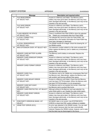
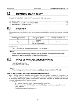
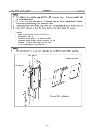
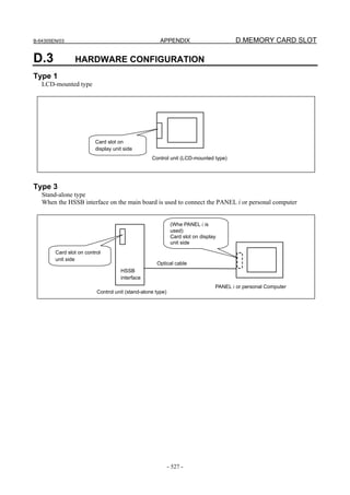
![APPENDIX B-64305EN/03
- 532 -
F. MAINTENANCE OF OPEN
CNC (BOOT-UP AND IPL)
System tray
Right-click the icon in the system tray, and the popup menu, shown below, appears.
Selecting [Open] causes the status screen to open.
Selecting [About] causes the version information dialog box to appear.
Selecting [End] causes Ncboot32.exe to terminate.
Double-clicking the icon in the system tray causes Open in the menu to be automatically selected.
F.2 CHANGING START SEQUENCES
By setting the rotary switch provided on the main board of the CNC main unit to the F position, you can
perform maintenance work using the BOOT and IPL screens.
Start-up sequence for the maintenance work (rotary switch position: F)
1. Wait until communication with the CNC is established.
2. Display the BOOT screen.
3. Display the IPL screen.
4. Display the CNC power-on screen.
5. Start FOCAS2.
6. Start a registered application program (such as CNC screen display function).
7. Perform monitoring for communication errors and CNC system alarms.
Start-up sequence for normal operation (rotary switch position: 0)
1. Wait until communication with the CNC is established.
2. Start FOCAS2.
3. Start a registered application program (such as CNC screen display function).
4. Perform monitoring for communication errors and CNC system alarms.
Asynchronous start-up sequence (rotary switch position: E)
1. The CNC starts without waiting for communication to be established.
2. After communication is established, the personal computer performs initialization described below.
3. Start FOCAS2.
4. Start a registered application program (such as CNC screen display function).
5. Perform monitoring for communication errors and CNC system alarms.](https://image.slidesharecdn.com/fanuc0imaintenancemanual-140802043306-phpapp01/85/Fanuc-0i-maintenance-manual-CNC-milling-machine-550-320.jpg)
![B-64305EN/03 APPENDIX
- 533 -
F.MAINTENANCE OF OPEN
CNC (BOOT-UP AND IPL)
• Location of rotary switch
• Stand-alone type Series 0i-D
Rotary switch
F.3 EXPLANATION OF SCREENS
NOTE
To open each screen of Ncboot32.exe, you are recommended to use either the
mouse or touch panel.
F.3.1 BOOT Screen
The area where the file is to be placed can be changed by using the [Setting...] button.](https://image.slidesharecdn.com/fanuc0imaintenancemanual-140802043306-phpapp01/85/Fanuc-0i-maintenance-manual-CNC-milling-machine-551-320.jpg)
![APPENDIX B-64305EN/03
- 534 -
F. MAINTENANCE OF OPEN
CNC (BOOT-UP AND IPL)
Select the memory card on the CNC or a personal computer folder. The file location may be changed at
any time.
"Memory Card on CNC": Specify the memory card slot of the CNC.
"Folder": Specify a folder on the PC.
To use the memory card slot beside PANEL i, select "Folder" and specify the drive name given to the
memory card by Windows.
F.3.1.1 System data manipulation
The following screen is used for manipulating system data (including control software and ladder
programs) on the CNC.
[Load...] opens the file selection screen. Specify a file to be loaded.
[Save] saves the selected system data on the CNC in a file.
[Check] checks the selected system data on the CNC.
[Delete] deletes the selected system data on the CNC.](https://image.slidesharecdn.com/fanuc0imaintenancemanual-140802043306-phpapp01/85/Fanuc-0i-maintenance-manual-CNC-milling-machine-552-320.jpg)
![B-64305EN/03 APPENDIX
- 535 -
F.MAINTENANCE OF OPEN
CNC (BOOT-UP AND IPL)
F.3.1.2 SRAM operation
This screen is used to store and restore CNC SRAM data.
[Backup]: Saves SRAM data to a file.
[Restore]: Restore SRAM data from a file.
The progress of the operation is indicated in the lower part of the screen. The name of the backup file is
automatically determined according to the SRAM size and cannot be changed.
The CNC has the automatic data backup (option) of automatically saving the data of SRAM in FROM.
The personal computer can restore the data that was saved automatically to SRAM. Press the
[AutoBackup...] button to display the following screen.
Select a saved image under "Name" and press the [Restore] button to restore the SRAM data of the
CNC.](https://image.slidesharecdn.com/fanuc0imaintenancemanual-140802043306-phpapp01/85/Fanuc-0i-maintenance-manual-CNC-milling-machine-553-320.jpg)
![APPENDIX B-64305EN/03
- 536 -
F. MAINTENANCE OF OPEN
CNC (BOOT-UP AND IPL)
F.3.1.3 File operation
The following screen is used for operating files on a memory card in the CNC or in a folder of the
personal computer.
[Delete] deletes a selected file.
[Format] formats the memory card. This button is valid when the memory card is selected by
[Setting...]
[Refresh] updates the file list to the latest state. After changing memory cards or floppy disks, click
this button.
F.3.2 IPL Screen
NOTE
The contents of the IPL screen vary depending on the CNC model. Follow the
instructions displayed in the menu.](https://image.slidesharecdn.com/fanuc0imaintenancemanual-140802043306-phpapp01/85/Fanuc-0i-maintenance-manual-CNC-milling-machine-554-320.jpg)
![APPENDIX B-64305EN/03
- 538 -
F. MAINTENANCE OF OPEN
CNC (BOOT-UP AND IPL)
F.4.2 Status Screen
To open the status screen, double-click the icon in the system tray. Alternatively, in the menu popped
up by right-clicking, click Open.
Node: Node number
Name: Node name. (Define the node name in advance by using the HSSB applet on the control panel.)
Bus: Hardware communication status (0: Communication error, 1: Communication established)
Status: Status (in hexadecimal)
Bit 2: End of BOOT processing
Bit 3: End of IPL processing
Bit 4: Rotary switch position 0
Bit 5: Display of 30 lines on IPL/system alarm screen
Bit 8: CNC system alarm
Pop up this window on communication error: By checking this item, this screen is opened automatically
when a communication error occurs.
Clicking the [Close] button closes the screen.
Clicking the [Setting...] button opens the option setting screen.
Clicking the [About...] button opens the version information screen.
F.4.3 Option Setting Screen
On the option setting screen, application programs can be registered.
Any programs for use with FOCAS2 will not run unless they are started after communication
establishment with CNC. By registering these programs in Ncboot32.exe, they can be executed in
synchronization with the start of FOCAS2. (Such as CNC screen display function)
Clicking the [Settings...] button on the status screen causes the option setting screen to open. On the
option setting screen, an application must be registered with each node that requires it. In addition, it is
possible to set the display of the BOOT/IPL screen during the next startup of the CNC.](https://image.slidesharecdn.com/fanuc0imaintenancemanual-140802043306-phpapp01/85/Fanuc-0i-maintenance-manual-CNC-milling-machine-556-320.jpg)
![B-64305EN/03 APPENDIX
- 539 -
F.MAINTENANCE OF OPEN
CNC (BOOT-UP AND IPL)
[Node] selects a node. In the list box in the center of the screen, the programs registered for the
selected node are displayed.
[New...] registers a new program. When a blank character is included in the path, it is enclosed
with double quotation marks.
[Remove] deletes a selected line.
[Edit] allows editing of a selected line. This button is used to edit arguments. The character
string %d in the command line is replaced by a node number. To represent % itself,
describe %%.
Example: To start the CNC screen display function after FOCAS2 starts at that node, code the following:
“C:Program FilesCNCScreenCNCScrn.exe” /Node=%d
To set the display of the BOOT/IPL screen during the next startup of the CNC, select the "Boot Option"
tab on the option setting screen.
If a CNC that is not grayed out is checked, the BOOT/IPL screen appears during the next startup of the
CNC, regardless of the setting of the rotary switch on the CNC side. This display setting is enabled only
once and automatically cleared by Ncboot32.exe.](https://image.slidesharecdn.com/fanuc0imaintenancemanual-140802043306-phpapp01/85/Fanuc-0i-maintenance-manual-CNC-milling-machine-557-320.jpg)
![G.IPL MONITOR APPENDIX B-64305EN/03
- 540 -
G IPL MONITOR
Appendix G, "IPL MONITOR", consists of the following sections:
G.1 OVERVIEW .....................................................................................................................................540
G.2 STARTING OF THE IPL MONITOR..............................................................................................540
G.3 IPL MENU........................................................................................................................................540
G.1 OVERVIEW
With the IPL monitor, the following operations can be performed:
1) Clearing of individual files
CNC parameters, tool compensation data, and so forth can be cleared.
2) Output of system alarm information
System alarm information that is stored in history information can be output to the memory card.
WARNING
1 From the IPL monitor menu, do not select an item other than the items listed
below.
The other items represent functions for FANUC service.
0. END IPL
3. CLEAR FILE
5. SYSTEM ALARM UTILITY
2 When an individual file is cleared, all data stored in the file is cleared and
initialized. So, before clearing an individual file, back up the data of the file as
needed.
3 If a system label error has occurred, perform a clear operation according to
Appendix H, "MEMORY CLEAR", instead of clearing of an individual file.
G.2 STARTING OF THE IPL MONITOR
The IPL monitor can be started according to the procedure below.
LCD-mounted type
<1> Turn on the power by pressing the MDI keys [.] and [-] simultaneously.
<2> The IPL monitor screen is displayed.
Stand-alone type
<1> Start NCBOOT32.
<2> Select "1. IPL MONITOR" on the IPL screen.
<3> The IPL monitor screen is displayed.
For details, see Appendix F, "MAINTENANCE OF OPEN CNC (BOOT-UP AND IPL)".](https://image.slidesharecdn.com/fanuc0imaintenancemanual-140802043306-phpapp01/85/Fanuc-0i-maintenance-manual-CNC-milling-machine-558-320.jpg)
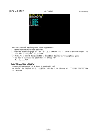

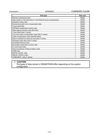

![B-64305EN/03 INDEX
i-1
INDEX
<Number>
7-SEGMENT LED INDICATIONS (BLINKING)......530
7-SEGMENT LED INDICATIONS (TURNED ON)..528
<α>
αi SERVO INFORMATION SCREEN .......................333
αi SERVO WARNING INTERFACE .........................332
<A>
About grounding types.................................................164
AC SPINDLE...............................................................337
ADJUSTING REFERENCE POSITION (DOG
METHOD) ...................................................................328
ALARM DS0300 (REQUEST FOR REFERENCE
POSITION RETURN) .................................................383
ALARM LIST..............................................................435
ALARM LIST (CNC)..................................................435
ALARM LIST (PMC)..................................................473
ALARM LIST (SERIAL SPINDLE) ...........................495
ALARM OH0700 (OVERHEAT: CONTROL UNIT).387
ALARM OH0701 (OVERHEAT: FAN MOTOR) ......387
ALARM PS0090 (REFERENCE POSITION
RETURN IS ABNORMAL) ........................................381
Alarm Related to Invalid Parameter Settings ...............326
ALARM SR0085 TO SR0087 (READER/PUNCHER
INTERFACE ALARM) ...............................................378
ALARM SV0401 (V READY OFF)............................384
ALARM SV0404 (V READY ON)..............................386
ALARM SV0417 (DIGITAL SERVO SYSTEM IS
ABNORMAL)..............................................................387
ALARM SV0462 (SEND CNC DATA FAILED) .......386
ALARM SV0463 (SEND SLAVE DATA FAILED)...386
ALARM SV5134 (FSSB: OPEN READY TIME
OUT)............................................................................388
ALARM SV5136 (FSSB: NUMBER OF AMPS IS
SMALL).......................................................................388
ALARM SV5137 (FSSB: CONFIGURATION
ERROR).......................................................................388
ALARM SV5197 (FSSB: OPEN TIME OUT) ............388
Alarms for built-in detectors (αi and βi Pulsecoders)
and troubleshooting actions..........................................420
Alarms for separate detectors and troubleshooting
actions ..........................................................................420
Alarms Related to Amplifiers and Motors ...................323
Alarms Related to Disconnection.................................325
Alarms Related to Serial Pulsecoder Communication..325
Alarms related to the αi Pulsecoder .............................324
Analog Input Separate Detector Interface Unit............139
Appearance inspection of the linear motor (magnet
plate) ............................................................................419
AUTOMATIC DATA BACKUP.................................189
AUTOMATIC OPERATION CANNOT BE DONE...367
Automatic Setting of Standard Parameters...................347
Automatic start of trace setting ....................................235
<B>
Backing up and Restoring Communication Parameters289
Basic Configuration of PMC........................................195
Basic Specifications .....................................................202
Basic Unit.......................................................................79
BOOT Screen...............................................................533
BOOT SYSTEM ..........................................................508
<C>
COUNTERMEASURES AGAINST NOISE...............164
Cabinet .........................................................................171
Cable clamp and shield processing...............................168
CAUTIONS IN REPLACING PCB’S .........................182
CHANGING START SEQUENCES ...........................532
Checking PMC Alarms ([ALARM] Screen) ................212
CNC Alarm Screen.......................................................537
CNC STATE DISPLAY ................................................30
Collective Monitor Function ........................................250
COLLECTIVE MONITOR Screen..............................251
COLOR SETTING SCREEN.........................................49
CONFIGURATION OF PRINTED CIRCUIT
BOARD CONNECTORS AND CARDS..................72,99
Confirming the Parameters Required for Data
Input/Output.................................................................185
Connecting the Ground Terminal of the Control Unit..173
Contents Displayed ........................................................15
CONTENTS-OF-MEMORY DISPLAY SCREEN........65
CORRECTIVE ACTION FOR FAILURES ................355
Correspondence between operation mode and
parameters on spindle tuning screen.............................345
CYCLE START LED SIGNAL HAS TURNED OFF.372
<D>
Data Input/Output ([I/O] Screen) .................................223
DATA TYPES TO BE CLEARED..............................544
DEFINITION OF WARNING, CAUTION, AND
NOTE............................................................................s-1
Demounting...............................................................89,90
Demounting a FROM/SRAM module..........................136
Detailed troubleshooting methods................................421
DeviceNet Board..........................................................119
DIAGNOSIS FUNCTION .............................................15
DIGITAL SERVO........................................................307
DISPLAY AND OPERATION........................................1
Display Formats on Contents-of-Memory Display
Screen.............................................................................66
Display Method.............................................12,32,65,340
Display of the servo amplifier operation status............427
Display Unit ...................................................................79
Displaying a Program List ([LIST] Screen) .................240
Displaying and operating the file list ...........................295
Displaying Diagnosis Screen..........................................15
Displaying I/O Link Connection Status ([I/OLNK]
Screen) .........................................................................225](https://image.slidesharecdn.com/fanuc0imaintenancemanual-140802043306-phpapp01/85/Fanuc-0i-maintenance-manual-CNC-milling-machine-565-320.jpg)
![INDEX B-64305EN/03
i-2
Displaying Servo Tuning Screen..................................322
Displaying the Maintenance Information Screen...........62
Displaying the Power ON Sequence ............................509
Distributed I/O Setting .................................................153
DOGLESS REFERENCE POSITION SETTING........330
<E>
Editing Ladder Programs .............................................245
EMBEDDED ETHERNET FUNCTION .....................276
EMBEDDED ETHERNET OPERATIONS.................291
EMBEDDED ETHERNET PORT AND PCMCIA
ETHERNET CARD.....................................................276
ENVIRONMENTAL CONDITIONS OUTSIDE
CABINET ....................................................................163
ERROR CODES (SERIAL SPINDLE)........................503
ERROR MESSAGES AND REQUIRED ACTIONS ..523
Example of setting the FOCAS2/Ethernet function .....280
Example of setting the FTP file transfer function ........284
Execution of Trace.......................................................232
EXPLANATION OF SCREENS .................................533
<F>
Fast Ethernet Board......................................................114
File operation ...............................................................536
FL-net Board................................................................127
FSSB DISPLAY AND SETTING SCREEN ...............316
FTP File Transfer Function..........................................291
Function Keys ..................................................................3
FUNCTION KEYS AND SOFT KEYS...........................1
Functions on the IPL screen.........................................537
<G>
General Screen Operations...............................................1
Grounding ....................................................................164
Grounding methods......................................................165
<H>
HANDLE OPERATION CANNOT BE DONE ..........362
HARDWARE CONFIGURATION ...................67,95,527
Hardware Configuration Screen.....................................12
HARDWARE OVERVIEW......................................68,96
<I>
I/O ...........................................................................80,106
I/O Communication Error Messages............................491
I/O Link-AS-i Converter..............................................141
I/O Signals of PMC......................................................195
IN A CONNECTOR PANEL I/O UNIT, DATA IS
INPUT TO AN UNEXPECTED ADDRESS...............376
IN A CONNECTOR PANEL I/O UNIT, NO DATA
IS OUTPUT TO AN EXPANSION UNIT...................377
INITIAL SETTING SERVO PARAMETERS ............307
INPUT AND OUTPUT OF DATA..............................183
INPUT FROM AND OUTPUT TO I/O DEVICES
CANNOT BE PERFORMED, INPUT/OUTPUT
CANNOT BE PERFORMED PROPERLY .................374
Inputting and Outputting Parameters..............................58
Inputting CNC Parameters ...........................................187
Inputting Custom Macro Variable Values....................188
Inputting Part Programs................................................188
Inputting Pitch Error Compensation Amount...............188
Inputting special characters..........................................298
Inputting Tool Compensation Amount.........................188
INPUTTING/ OUTPUTTING DATA .........................185
INSERTING AND EXTRACTING OPTION PCB.....130
INTERFACE BETWEEN CNC AND PMC................194
Investigating the Conditions under which Failure
Occurred.......................................................................355
IPL MENU...................................................................541
IPL MONITOR ............................................................540
IPL Screen....................................................................536
<J>
JOG OPERATION CANNOT BE DONE....................359
<L>
LADDER DIAGRAM MONITOR AND EDITOR
SCREENS ([PMCLAD])..............................................239
LCD-MOUNTED TYPE CNC HARDWARE...............67
LED DISPLAY ............................................................528
LIQUID CRYSTAL DISPLAY (LCD)..........................91
LIST OF ADDRESSES................................................254
List of Basic Units........................................................105
LIST OF MAINTENANCE PARTS............................507
LIST OF MANUALS RELATED TO MOTORS
AND AMPLIFIERS.....................................................410
List of Printed Circuit Boards ......................................105
LIST OF UNITS AND PRINTED CIRCUIT
BOARDS.................................................................79,105
LOAD BASIC SYSTEM .............................................523
LOG SCREEN OF THE EMBEDDED ETHERNET
FUNCTION..................................................................303
<M>
Main Board ....................................................................72
Main inspection items ..................................................413
MAINTENANCE INFORMATION SCREEN..............61
Maintenance of a Detector ...........................................419
Maintenance of a Servo Amplifier ...............................427
Maintenance of βiS motor Pulsecoders........................422
MAINTENANCE OF OPEN CNC (BOOT-UP AND
IPL) ..............................................................................531
MAINTENANCE OF STAND-ALONE TYPE UNIT 111
Maintenance of the FANUC-NSK spindle unit............418
MAINTENANCE SCREEN FOR EMBEDDED
ETHERNET FUNCTION ............................................299
MATTERS COMMON TO BOTH LCD-MOUNTED
TYPE AND STAND-ALONE TYPE (HARDWARE) 114
MDI Unit........................................................................79
Measures Against Surges due to Lightning..................178
MEMORY CARD FORMAT Screen...........................522
MEMORY CARD SLOT.............................................525
MEMORY CLEAR......................................................543
Messages That May Be Displayed on the PMC Alarm
Screen...........................................................................473
Method A of gear change for M series (Bit 2 (SGB) of
Parameter No.3705 = 0) ...............................................339](https://image.slidesharecdn.com/fanuc0imaintenancemanual-140802043306-phpapp01/85/Fanuc-0i-maintenance-manual-CNC-milling-machine-566-320.jpg)
![B-64305EN/03 INDEX
i-3
Method B of gear change for M series (Bit 2 (SGB) of
Parameter No.3705 = 1) ...............................................339
Method of Extraction ............................................130,133
Method of Insertion...............................................130,134
MONITORING I/O DIAGNOSIS ([I/ODGN]
SCREEN).....................................................................236
Monitoring Ladder Diagrams ([LADDER] Screen).....242
Monitoring PMC Signal Status ([STATUS] Screen) ...210
MOTOR/DETECTOR/AMPLIFIER PREVENTIVE
MAINTENANCE ........................................................409
Mounting...................................................................89,90
Mounting a FROM/SRAM module..............................136
MOUNTING AND DEMOUNTING AXIS CARD.....132
MOUNTING AND DEMOUNTING FROM/SRAM
MODULE.....................................................................136
MOUNTING AND DEMOUNTING LCD/MDI UNIT.88
Mounting or Demounting a 10.4” LCD Unit .................89
Mounting or Demounting an MDI Unit (Small Type) ...90
<N>
NET EDITOR Screen ..................................................247
NO MANUAL OPERATION NOR AUTOMATIC
OPERATION CAN BE EXECUTED..........................356
Noise Suppressor..........................................................177
Notes .........................................................................53,61
Notes on motor cleaning ..............................................416
Notes on the cutting fluid (informational)....................416
NOTHING IS DISPLAYED ON THE LCD WHEN
THE POWER IS TURNED ON...................................373
<O>
OPERATING MONITOR..............................................32
Operating the Maintenance Information Screen.............63
OPERATING THE PMC SCREEN.............................207
Operation......................................................................112
Operation after execution of trace................................233
Operation Errors...........................................................480
OPERATION METHOD .............................................543
Operation of Each Function .........................................113
Operation on the FOCAS2/Ethernet setting screen......277
Operation on the FTP file transfer setting screen.........281
Operations for Color Setting ..........................................50
Operations on the System Alarm Screen......................393
Option Setting Screen ..................................................538
OPTIONAL BOARD...................................................114
OTHER SCREENS......................................................537
Other Units.......................................................81,106,138
Others...........................................................................327
Outline of Spindle Control...........................................338
Outputting CNC Parameters.........................................186
Outputting Custom Macro Variable Values.................187
Outputting Data..............................................................44
Outputting Part Program ..............................................187
Outputting Pitch Error Compensation Amount............186
Outputting System Configuration Data..........................14
Outputting Tool Compensation Amount......................187
<P>
Parameter ..................................................................51,64
Parameter Setting .........................................................322
Parameters.................................................................33,59
Periodic cleaning of a motor ........................................415
PMC DIAGNOSIS AND MAINTENANCE
SCREENS ([PMCMNT]).............................................210
PMC Signal Addresses.................................................196
PMC SPECIFICATIONS.............................................202
PMC System Alarm Messages.....................................477
POWER MATE CNC MANAGER FUNCTION...........53
PREFACE .................................................................... p-1
Preventive Maintenance of a Built-in Spindle Motor
and Spindle Unit...........................................................417
Preventive Maintenance of a Linear Motor..................418
Preventive Maintenance of a Motor (Common to All
Models) ........................................................................413
Preventive Maintenance of a Servo Amplifier .............426
PREVENTIVE MAINTENANCE OF MOTORS AND
DETECTORS...............................................................411
PREVENTIVE MAINTENANCE OF SERVO
AMPLIFIERS ..............................................................423
Printed Circuit Boards....................................................79
PROFIBUS-DP Board..................................................117
PROGRAM LIST EDITOR Screen .............................249
<R>
Related NC parameters..........................................283,289
Replacement of a fan motor .........................................430
REPLACING A FAN UNIT ........................................109
Replacing Batteries ......................................................179
REPLACING BATTERY ..............................................84
REPLACING BATTERY FOR ABSOLUTE
PULSECODERS..........................................................179
REPLACING FAN MOTORS.......................................87
REPLACING FUSE ON CONTROL UNIT..................83
REPLACING FUSES ON VARIOUS UNITS.............157
Replacing the Batteries in a Separate Battery Case......180
REPLACING THE BATTERY ...................................107
Replacing the Battery Built into the Servo Amplifier ..180
REPLACING THE FUSE OF THE CONTROL
UNIT............................................................................106
REPLACING THE MAIN BOARD ..............................81
RESTART OF THE EMBEDDED ETHERNET.........299
Routine inspection of the FANUC-NSK spindle unit ..417
<S>
SAFETY PRECAUTIONS ...........................................s-1
SCREEN CONFIGURATION AND OPERATING
PROCEDURE..............................................................512
Screen Display ..........................................................49,53
Separate Detector Interface Unit ..................................138
Separating Signal Lines................................................176
SERIAL INTERFACE AC SPINDLE .........................338
SERVO ALARMS (SV04**, SV06**)........................389
SERVO TUNING SCREEN ........................................322
Setting and Displaying Counter Values ([COUNTR]
Screen) .........................................................................215](https://image.slidesharecdn.com/fanuc0imaintenancemanual-140802043306-phpapp01/85/Fanuc-0i-maintenance-manual-CNC-milling-machine-567-320.jpg)
![INDEX B-64305EN/03
i-4
Setting and Displaying Data Tables ([DATA] Screen) 218
Setting and Displaying Keep Relays ([KEEPRL]
Screen) .........................................................................217
Setting and Displaying Variable Timers ([TIMER]
Screen) .........................................................................213
SETTING I/O MODULES...........................................153
Setting of the FOCAS2/Ethernet Function...................277
Setting of the FTP File Transfer Function....................280
Setting of Trace Parameter ([TRCPRM] Screen).........228
SETTING PARAMETERS FOR INPUT/OUTPUT....183
Setting up DHCP..........................................................286
Setting up DNS ............................................................285
Setting Up the DNS/DHCP Function...........................285
SETTING UP THE EMBEDDED ETHERNET
FUNCTION .................................................................277
Signal Trace Function ([TRACE] Screen) ...................227
Single-Byte Kana Input on the Maintenance
Information Screen.........................................................63
Soft Key Structure............................................................1
Soft Keys..........................................................................3
Software Configuration Screen ......................................13
SPC ALARMS (SV03**) ............................................391
SPINDLE ALARMS (SP90**)....................................391
Spindle Information Screen..........................................350
Spindle monitor screen.................................................343
Spindle Setting and Tuning Screen ..............................340
Spindle setting screen...................................................340
Spindle tuning screen ...................................................341
SRAM DATA UTILITY Screen..................................520
SRAM operation ..........................................................535
STAND-ALONE TYPE CNC SERIES HARDWARE..94
STARTING OF THE IPL MONITOR.........................540
Starting the Boot System..............................................509
Status Screen................................................................538
Storage method of the FANUC-NSK spindle unit .......418
SWITCHING BETWEEN THE EMBEDDED
ETHERNET DEVICES ...............................................291
System Alarm 401 (EXTERNAL BUS INVALID
ADDRESS) ..................................................................397
System Alarm 403 (S-BUS TIME OUT ERROR).......398
System Alarm 404 (ECC UNCORRECTABLE
ERROR).......................................................................399
System Alarm 500 (SRAM DATA ERROR(SRAM
MODULE))..................................................................400
System Alarm 502 (NOISE ON POWER SUPPLY) ...401
System Alarm 503 (ABNORMAL POWER SUPPLY)402
SYSTEM ALARMS (SYS ALM***)..........................391
System Alarms 114 to 137 (Alarms on the FSSB).......402
System Alarms Detected by Hardware ........................396
SYSTEM ALARMS RELATED TO THE PMC AND
I/O Link (SYS_ALM197) ............................................404
SYSTEM CONFIGURATION SCREEN ......................12
SYSTEM DATA CHECK Screen................................515
SYSTEM DATA DELETE Screen ..............................517
System data manipulation ............................................534
SYSTEM DATA SAVE Screen...................................518
System Files and User Files .........................................511
System Relay Addresses (R9000)................................198
<T>
T series.........................................................................339
Terminal Board Type I/O Module................................147
Terminal Type I/O Module Setting..............................156
Test run of the FANUC-NSK spindle unit ...................418
TOTAL CONNECTION DIAGRAMS.....................69,97
Tracing Data...................................................................43
Transferring programs..................................................296
Transition of the PMC Screens ....................................209
TROUBLESHOOTING ...............................................354
TYPES OF AVAILABLE MEMORY CARDS...........525
<U>
USER DATA LOADING/SYSTEM DATA
LOADING Screen........................................................513
<W>
Warning Interface.........................................................349
WARNINGS RELATED TO CHECK OPERATION ..s-1
WARNINGS RELATED TO PARAMETERS.............s-3
WARNINGS RELATED TO REPLACEMENT ..........s-2
Warnings that Occurs on the Maintenance Information
Screen.............................................................................64
Warnings, Cautions, and Notes on Preventive
Maintenance of Motors and Detectors .........................411
Warnings, Cautions, and Notes on Preventive
Maintenance of Servo Amplifiers ................................423
WARNINGS, CAUTIONS, AND NOTES RELATED
TO DAILY MAINTENANCE......................................s-3
WAVEFORM DIAGNOSIS DISPLAY.........................33
Waveform Diagnosis Graph Screen ...............................34
Waveform Diagnosis Parameter Screen.........................35
WHAT IS PMC?..........................................................195](https://image.slidesharecdn.com/fanuc0imaintenancemanual-140802043306-phpapp01/85/Fanuc-0i-maintenance-manual-CNC-milling-machine-568-320.jpg)
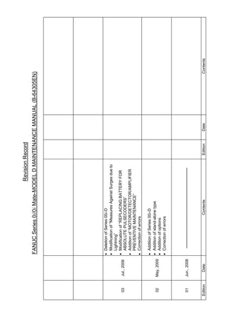

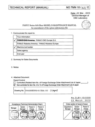
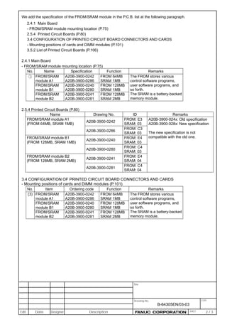
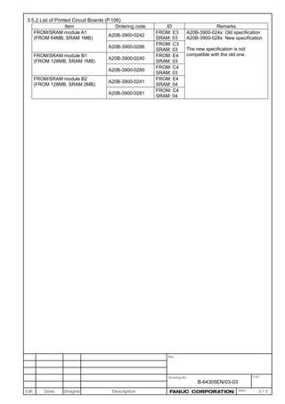
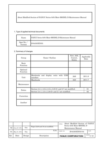
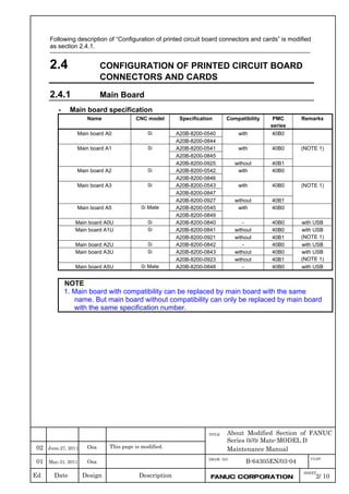
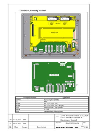
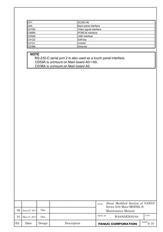
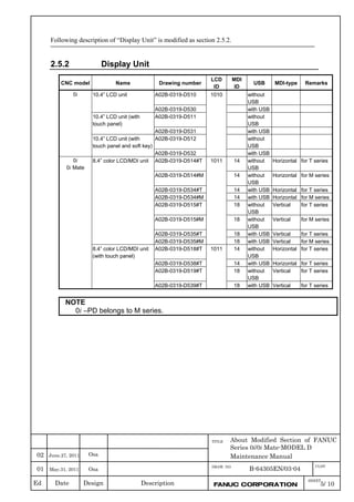
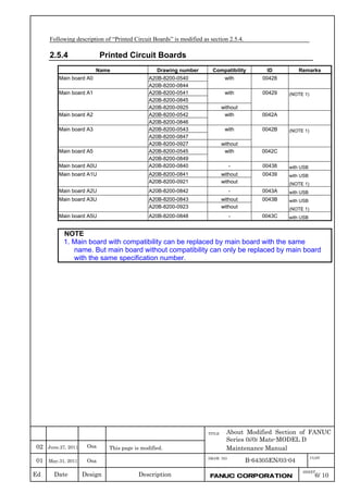
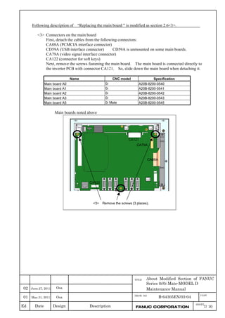
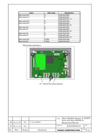
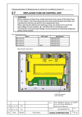
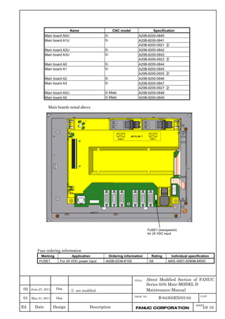

This maintenance manual provides instructions for maintaining FANUC Series 0i-D and Series 0i Mate-D CNC systems. It describes the display and operation screens, hardware configuration, input/output of data, interface with the PMC, embedded Ethernet function, servo and spindle tuning, troubleshooting procedures, and preventative maintenance of motors, detectors, and amplifiers. The manual also includes appendices with alarm lists, lists of maintenance parts, and information on boot systems, memory cards, LED displays, and memory clearing.