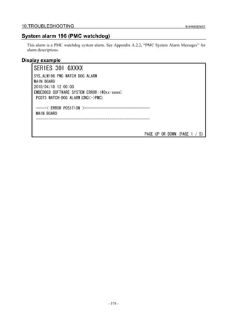
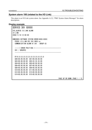
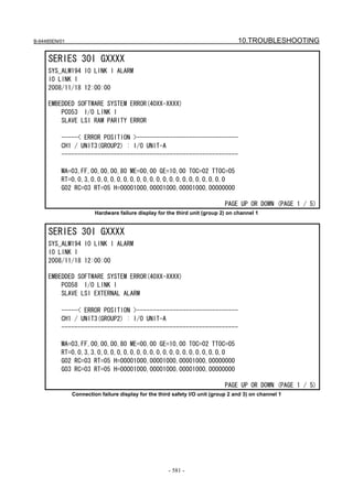
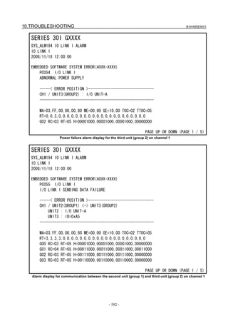
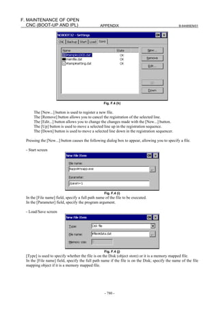
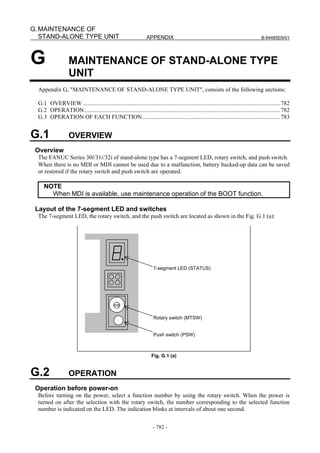
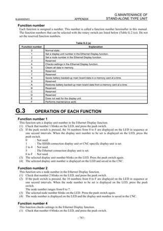
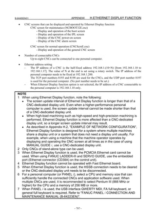
This document provides safety precautions for maintenance of CNC units. It contains 7 warnings related to replacing components, emphasizing the need to shut off all power, discharge static electricity, and wait for components to cool before exchange to avoid electric shock or other injuries. It also describes 5 warnings related to checking machine operation, such as verifying correct data and speeds, to prevent unexpected machine movement that could damage the machine or workpiece.


![TABLE OF CONTENTS B-64485EN/01
4.2 UNITS SUPPORTING I/O Link i ........................................................................ 285
4.2.1 Items Common to Units Supporting I/O Link i....................................................285
4.2.2 I/O Module for Connector Panel [Supporting I/O Link i]....................................286
4.2.3 I/O Module for Operator’s Panel (Supporting Matrix Input)
[Supporting I/O Link i].........................................................................................289
4.2.4 Connection of I/O Module for Operator's Panel and I/O Module for Power
Magnetics Cabinet [Supporting I/O Link i]..........................................................290
4.2.5 I/O Module Type-2 for Connector Panel [Supporting I/O Link i] .......................291
4.2.6 Terminal Type I/O Module [Supporting I/O Link i] ............................................293
4.2.7 I/O Link Connection Unit [Supporting I/O Link i] ..............................................298
4.2.8 Standard Machine Operator's Panel [Supporting I/O Link i] ...............................300
4.3 UNITS SUPPORTING I/O Link .................................................................. 302
4.3.1 I/O Link-AS-i Converter ......................................................................................302
4.4 SEPARATE DETECTOR INTERFACE UNIT ............................................ 310
4.5 Analog Input Separate Detector Interface Unit .......................................... 311
4.6 PANEL i.................................................................................................................. 312
4.6.1 Replacing the Battery ...........................................................................................312
4.6.2 Replacing the Fan.................................................................................................314
4.6.2.1 Replacing the fan in the PANEL i ................................................................... 314
4.6.2.2 Replacing the fan for the HDD........................................................................ 315
4.6.3 Replacing the Touch Panel Protection Sheet........................................................315
4.7 REPLACING BATTERY FOR ABSOLUTE PULSECODERS .................... 316
4.7.1 Overview ..............................................................................................................316
4.7.2 Replacing Batteries...............................................................................................316
4.7.3 Replacing the Batteries in a Separate Battery Case..............................................317
4.7.4 Replacing the Battery Built into the Servo Amplifier ..........................................317
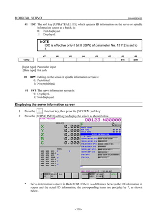
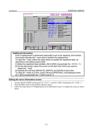
5 INPUT AND OUTPUT OF DATA......................................................... 319
5.1 SETTING PARAMETERS FOR INPUT/OUTPUT...................................... 319
5.2 INPUTTING/ OUTPUTTING DATA............................................................ 320
5.2.1 Confirming the Parameters Required for Data Output .........................................321
5.2.2 Outputting CNC Parameters.................................................................................322
5.2.3 Outputting Pitch Error Compensation Amount ....................................................323
5.2.4 Outputting Custom Macro Variable Values .........................................................323
5.2.5 Outputting Tool Compensation Amount ..............................................................323
5.2.6 Outputting Part Program ......................................................................................323
5.2.7 Inputting CNC Parameters ...................................................................................324
5.2.8 Inputting Pitch Error Compensation Amount.......................................................325
5.2.9 Inputting Custom Macro Variable Values............................................................326
5.2.10 Inputting Tool Compensation Amount.................................................................326
5.2.11 Inputting Part Programs........................................................................................326
5.3 AUTOMATIC DATA BACKUP ................................................................... 327
6 INTERFACE BETWEEN CNC AND PMC........................................... 332
6.1 WHAT IS PMC?......................................................................................... 332
6.1.1 Basic Configuration of PMC ................................................................................332
6.1.2 I/O Signals of PMC ..............................................................................................332
6.1.3 PMC Signal Addresses .........................................................................................333
6.1.4 Communication Method for External I/O Device ................................................335
6.2 MULTI-PMC FUNCTION ........................................................................... 336
6.2.1 Execution Order and Execution Time Percentage................................................337
6.2.2 Setting I/O Address for I/O Link i and I/O Link ..................................................338
6.2.3 Interface Between CNC and PMC .......................................................................339
c-4](https://image.slidesharecdn.com/b-64485en01-121129013453-phpapp02/85/B-64485-en-01-16-320.jpg)
![B-64485EN/01 TABLE OF CONTENTS
6.2.4 Multi-Path PMC Interface ....................................................................................340
6.2.5 System Relay Addresses (R9000, Z0)..................................................................341
6.3 PMC SPECIFICATIONS............................................................................ 346
6.3.1 Basic Specifications .............................................................................................346
6.3.2 Addresses..............................................................................................................350
6.4 OPERATING THE PMC SCREEN............................................................. 352
6.4.1 Transition of the PMC Screens.............................................................................354
6.5 PMC DIAGNOSIS AND MAINTENANCE SCREENS ([PMC MAINTE]) .... 355
6.5.1 Monitoring PMC Signal Status ([STATUS] Screen) ...........................................355
6.5.2 Checking PMC Alarms ([PMC ALARM] Screen)...............................................356
6.5.3 Setting and Displaying Variable Timers ([TIMER] Screen)................................357
6.5.4 Setting and Displaying Counter Values ([COUNTR] Screen) .............................359
6.5.5 Setting and Displaying Keep Relays ([KEEP RELAY] Screen)..........................360
6.5.6 Setting and Displaying Data Tables ([DATA] Screen) ........................................361
6.5.7 Data Input/Output ([I/O] Screen) .........................................................................367
6.5.8 Displaying i/o devices connection status ([I/O DEVICE] screen) .......................370
6.5.9 Signal Trace Function ([TRACE] Screen) ...........................................................372
6.5.10 Setting of Trace Parameter ([TRACE SETING] Screen).....................................373
6.5.11 Execution of Trace ...............................................................................................376
6.5.11.1 Operation after execution of trace ................................................................... 377
6.5.11.2 Automatic start of trace setting ........................................................................ 380
6.5.12 MONITORING I/O DIAGNOSIS ([I/O DGN] SCREEN) ..................................380
6.6 LADDER DIAGRAM MONITOR AND EDITOR SCREENS
([PMC LADDER])....................................................................................... 384
6.6.1 Displaying a Program List ([LIST] Screen) .........................................................385
6.6.2 Monitoring Ladder Diagrams ([LADDER] Screen).............................................386
6.6.3 Editing Ladder Programs......................................................................................389
6.6.3.1 NET EDITOR screen....................................................................................... 391
6.6.4 PROGRAM LIST EDITOR Screen .....................................................................393
6.6.5 Collective Monitor Function ................................................................................394
6.6.5.1 COLLECTIVE MONITOR function............................................................... 395
6.7 LIST OF ADDRESSES .............................................................................. 398
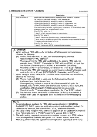
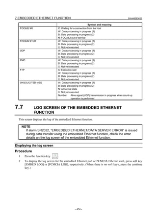
7 EMBEDDED ETHERNET FUNCTION ................................................ 435
7.1 EMBEDDED ETHERNET PORT AND PCMCIA ETHERNET CARD......... 435
7.2 SETTING UP THE EMBEDDED ETHERNET FUNCTION ........................ 437
7.2.1 Setting of the FOCAS2/Ethernet Function...........................................................437
7.2.1.1 Operation on the FOCAS2/Ethernet setting screen ......................................... 438
7.2.1.2 Example of setting the FOCAS2/Ethernet function......................................... 440
7.2.2 Setting of the FTP File Transfer Function............................................................440
7.2.2.1 Operation on the FTP file transfer setting screen ............................................ 441
7.2.2.2 Related NC parameters .................................................................................... 443
7.2.2.3 Example of setting the FTP file transfer function............................................ 443
7.2.3 Setting Up the DNS/DHCP Function ...................................................................444
7.2.3.1 Setting up DNS................................................................................................ 444
7.2.3.2 Setting up DHCP ............................................................................................. 445
7.2.3.3 Related NC parameters .................................................................................... 447
7.2.4 Setting of the Unsolicited Messaging Function....................................................448
7.2.4.1 Overview ......................................................................................................... 448
7.2.4.2 Setting of the FOCAS2/Ethernet function ....................................................... 449
7.2.4.3 Mode selection................................................................................................. 452
7.2.4.4 Setting on the CNC screen............................................................................... 454
7.2.4.5 Setting on the personal computer..................................................................... 457
7.2.4.6 Execution methods........................................................................................... 457
c-5](https://image.slidesharecdn.com/b-64485en01-121129013453-phpapp02/85/B-64485-en-01-17-320.jpg)


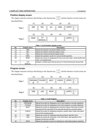
![B-64485EN/01 1.DISPLAY AND OPERATION
Press this key to display the program screen.
Press this key to display the offset/setting screen.
Press this key to display the system screen.
Press this key to display the message screen.
Press this key to display the graphics screen.
Press this key to display the custom screen 1 (conversational macro screen or C Language Executor
screen).
Press this key to display the custom screen 2 (conversational macro screen or C Language Executor
screen).
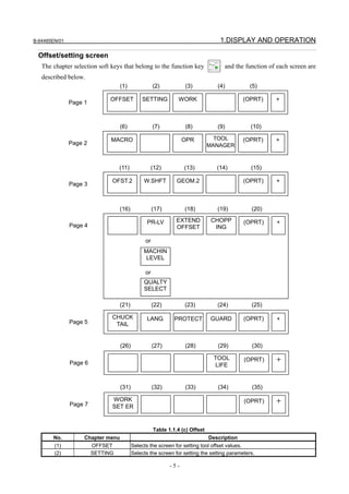
1.1.4 Soft Keys
By pressing a soft key after a function key, the corresponding screen of the function can be displayed.
The chapter selection soft keys of each function are described below.
The horizontal four keys on the right-hand side are assigned to chapter selection soft keys. When multiple
pages are used for chapter selection soft keys, [+] is displayed on the continuous menu key (rightmost soft
key). Press the continuous menu key to switch between chapter selection soft keys.
NOTE
1 Press function keys to switch between screens that are used frequently.
2 Some soft keys are not displayed depending on the option configuration.
If position indications are provided on the left half of the screen when a key other than the function key
is pressed, the left half of the soft keys is displayed as follows at all times:
-3-](https://image.slidesharecdn.com/b-64485en01-121129013453-phpapp02/85/B-64485-en-01-25-320.jpg)


![B-64485EN/01 1.DISPLAY AND OPERATION
(1) (2) (3) (4) (5)
PARAM GRAPH (OPRT) +
Page 1
Table 1.1.4 (f) Graphic
No. Chapter menu Description
(1) PARAM Selects the screen for setting graphic parameters.
(2) GRAPH Selects the screen for graphically displaying the tool path.
When the dynamic graphic display function is enabled:
(1) (2) (3) (4) (5)
DRAW PATH ANIME TOOL (OPRT)
Page 1 PARAM EXEC EXEC POS
Table 1.1.4 (g) Graphic
No. Chapter menu Description
(1) DRAW PARAM Selects the screen for setting drawing parameters.
(2) PATH EXEC Selects the screen for drawing tool paths.
(3) ANIME EXEC Selects the screen for drawing animation.
(4) TOOL POS Selects the screen for displaying tool positions.
1.2 SYSTEM CONFIGURATION SCREEN
After the system has started normally, you can find the types of installed printed circuit boards and
software types by displaying a system configuration screen.
1.2.1 Display Method
1 Press function key .
2 Press soft key [SYSTEM].
3 Two types of system configuration screen, the hardware screen and software screen, are provided,
and you can switch between these screens by using the page keys.
When all information cannot be displayed on one page of the screen, you can switch to the next page
by using the keys.
-9-](https://image.slidesharecdn.com/b-64485en01-121129013453-phpapp02/85/B-64485-en-01-31-320.jpg)


![B-64485EN/01 1.DISPLAY AND OPERATION
System Software type
EMBED ETHER Control software for embedded Ethernet function
PROFI SOFT Software for PROFIBUS function
PROFI MASTER Control software for PROFIBUS master function
PROFI SLAVE Control software for PROFIBUS slave function
DEVNT SOFT Software for DeviceNet function
DEVNT MASTER Control software for DeviceNet master function
DEVNT SLAVE Control software for DeviceNet slave function
ETHERNET Control software for fast Data Server
CMB(SYSTEM) Customers' board system software
CMB(USER) Customers' board user software
USB SOFT Control software for USB function
• Display of macro executor
The series and edition are displayed for each number specified at the time of P-CODE macro
creation.
Up to 20 types of macro executor are displayed.
1.2.4 Outputting System Configuration Data
Data displayed on the system configuration screen can be output to an input/output device.
(1) Press function key .
(2) Press the EDIT switch on the machine operator's panel.
(3) Press soft key [SYSTEM] to display the system configuration screen.
(4) Press soft key [(OPRT)] and select soft key [PUNCH].
(5) Press soft key [EXCE].
(6) Data is output to the output device selected by parameter No. 20.
Data is output to a file named SYS_CONF.TXT.
1.3 DIAGNOSIS FUNCTION
1.3.1 Displaying Diagnosis Screen
(1) Press function key .
(2) Press soft key [DGNOS], then a diagnosis screen is displayed.
1.3.2 Contents Displayed
Causes when the machine does not travel in spite of giving a command
Diagnosis 0 CNC internal state 1
[Data type] Bit
NAME Internal state when "1" is displayed
INPOSITION CHECK In-position check is being done.
FEEDRATE OVERRIDE 0% Feedrate override is 0%.
JOG FEED OVERRIDE 0% Jog feedrate override is 0%.
INTER/START LOCK ON Interlock/start lock is on.
SPEED ARRIVAL ON The system is waiting for the speed arrival signal to turn
on.
- 13 -](https://image.slidesharecdn.com/b-64485en01-121129013453-phpapp02/85/B-64485-en-01-35-320.jpg)
![1.DISPLAY AND OPERATION B-64485EN/01
WAIT REVOLUTION The system is waiting for the spindle one-rotation signal
in threading.
STOP POSITION OCDER The system is waiting for the rotation of the position
coder in spindle feed per revolution.
FEED STOP A feed stop was made.
Diagnosis 2 Dwell execution state
When a dwell is being executed, "1" is displayed.
Diagnosis 8 CNC internal state 2
[Data type] Bit
NAME Internal state when "1" is displayed
FOREGROUND READING Data is being input in the foreground.
BACKGROUND READING Data is being input in the background.
Reader/puncher interface output state
Diagnosis 10 Reader/puncher interface output state
When data is being output through the reader/puncher interface, "1" is indicated.
State of TH alarm
Diagnosis 30 TH alarm character count (foreground edit)
[Data type] 2-word axis
The position where the TH alarm occurred in foreground input is indicated by the number
of characters from the beginning of the block.
Diagnosis 31 TH alarm character code (foreground edit)
[Data type] 2-word axis
The character code of the character at which the TH alarm occurred in foreground input is
indicated.
Diagnosis 32 TH alarm character count (background edit)
[Data type] 2-word axis
The position where the TH alarm occurred in background input is indicated by the
number of characters from the beginning of the block.
Diagnosis 33 TH alarm character code (background edit)
[Data type] 2-word axis
The character code of the character at which the TH alarm occurred in background input
is indicated.
Display language of the CNC screen
Diagnosis 43 Number of the current display language of the CNC screen
[Data type] Byte
The number of the current display language of the CNC screen is indicated.
The correspondence between languages and numbers is show below.
0 : English
1 : Japanese
2 : German
3 : French
4 : Chinese (traditional characters)
5 : Italian
6 : Korean
7 : Spanish
8 : Dutch
- 14 -](https://image.slidesharecdn.com/b-64485en01-121129013453-phpapp02/85/B-64485-en-01-36-320.jpg)

![B-64485EN/01 1.DISPLAY AND OPERATION
Position error amount
Diagnosis 300 Position error of an axis in detection unit
Feed rate [mm/min] × 100 1
Position error = ×
60 × servo loop gain [1/sec] Detection unit
Machine position
Diagnosis 301 Distance from reference position of an axis in detection unit
Distance from the end of the deceleration dog to the first grid point
Diagnosis 302 Distance from the end of the deceleration dog to the first grid point
[Data type] Real axis
[Unit of data] Machine unit
[Valid data range] 0 to ±99999999
NOTE
For the reference position setting without a dog, the distance from
the beginning of the reference position setting without a dog to the
first grid point is assumed.
Reference counter
Diagnosis 304 Reference counter amount in each axis
[Data type] 2-word axis
[Unit of data] Detection unit
[Valid data range] –99999999 to 99999999
Motor temperature information
Diagnosis 308 Servo motor temperature (°C)
[Data type] Byte axis
[Unit of data] °C
[Valid data range] 0 to 255
The temperature of the coil of the servo motor is indicated. When the temperature reaches
140°C, a motor overheat alarm is issued.
Diagnosis 309 Pulsecoder temperature (°C)
[Data type] Byte axis
[Unit of data] °C
[Valid data range] 0 to 255
The temperature of the printed circuit board in the Pulsecoder is indicated. When the
temperature reaches 100°C (approximately 85°C for the temperature of atmosphere in the
Pulsecoder), a motor overheat alarm is issued.
NOTE
1 Temperature information has the following error:
• 50°C to 160°C ±5°C
• 160°C to 180°C ±10°C
2 The temperature at which an overheat alarm is issued has an error
of up to 5°C.
- 17 -](https://image.slidesharecdn.com/b-64485en01-121129013453-phpapp02/85/B-64485-en-01-39-320.jpg)


![B-64485EN/01 1.DISPLAY AND OPERATION
Diagnosis 360 Cumulative value of specified pulses (NC)
[Data type] 2-word
[Unit of data] Detection unit
[Valid data range] -99999999 to 99999999
Cumulative value of move commands distributed from the CNC since power-on is
indicated.
Diagnosis 361 Compensation pulses (NC)
[Data type] 2-word
[Unit of data] Detection unit
[Valid data range] -99999999 to 99999999
Cumulative value of compensation pulses (backlash compensation, pitch error
compensation, and so on) distributed from the CNC since power-on is indicated.
Diagnosis 362 Cumulative value of specified pulses (SV)
[Data type] 2-word
[Unit of data] Detection unit
[Valid data range] -99999999 to 99999999
Cumulative value of move pulses and compensation pulses received by the servo system
since power-on is indicated.
Diagnosis 363 Cumulative feedback (SV)
[Data type] 2-word
[Unit of data] Detection unit
[Valid data range] -99999999 to 99999999
Cumulative value of positional feedback pulses the servo system received from the pulse
coder since power-on is indicated.
Diagnosis data related to the Inductosyn absolute position detector
Diagnosis 380 Difference between the absolute position of the motor and offset data
[Data type] 2-word axis
[Unit of data] Detection unit
M (absolute position of the motor)-S (offset data)
λ (pitch interval)
The remainder resulting from the division is displayed.
Diagnosis 381 Offset data from the Inductosyn
[Data type] 2-word axis
[Unit of data] Detection unit
Off set data is displayed when CNC calculates the machine position.
Diagnosis data related to the serial spindles
#7 #6 #5 #4 #3 #2 #1 #0
Diagnosis 400 LNK
#7 LNK Communication with the spindle control side has been established.
Diagnosis 403 Temperature of spindle motor
[Data type] Byte spindle
[Unit of data] °C
[Valid data range] 0 to 255
The temperature of the winding of the spindle motor is indicated.
This information can be used to determine the overheat alarm of the spindle.
(The temperature that causes an overheat alarm varies from motor to motor.)
- 25 -](https://image.slidesharecdn.com/b-64485en01-121129013453-phpapp02/85/B-64485-en-01-47-320.jpg)
![1.DISPLAY AND OPERATION B-64485EN/01
NOTE
1 Temperature information has the following error:
• 50°C to 160°C ±5°C
• 160°C to 180°C ±10°C
2 The indicated temperature and the temperature causing an
overheat alarm have the following error:
• For lower than 160°C 5°C maximum
• For 160 to 180°C 10°C maximum
#7 #6 #5 #4 #3 #2 #1 #0
Diagnosis 408 SSA SCA CME CER SNE FRE CRE
#0 CRE A CRC error occurred (warning).
#1 FRE A framing error occurred (warning).
#2 SNE The sender or receiver is not correct.
#3 CER An abnormality occurred during reception.
#4 CME No response was returned during automatic scanning.
#5 SCA A communication alarm was issued on the spindle amplifier side.
#7 SSA A system alarm was issued on the spindle amplifier side.
(The above conditions are major causes of alarm SP0749. These conditions are caused
mainly by noise, a broken wire, a momentary failure of power, and so on.)
Diagnosis 410 Spindle load meter indication [%]
[Data type] Word spindle
[Unit of data] %
-1
Diagnosis 411 Spindle load meter indication [min ]
[Data type] Word spindle
[Unit of data] min-1
Diagnosis 417 Spindle position coder feedback information
[Data type] 2-word spindle
[Unit of data] Detection unit
Diagnosis 418 Positional deviation of spindle in position loop mode
[Data type] 2-word spindle
[Unit of data] Detection unit
Diagnosis 425 Spindle synchronization error
[Data type] 2-word spindle
[Unit of data] Detection unit
When the spindles are in synchronization mode, the absolute value of the synchronization
error when each spindle is set as the slave axis is indicated.
Diagnosis 445 Spindle position data
[Data type] Word spindle
[Unit of data] Pulse
[Valid data range] 0 to 4095
For the serial spindle, position coder signal pulse data from the one-rotation signal is
indicated as the position data of the spindle.
This data is valid when bit 1 of parameter No. 3117 is set to 1.
To display spindle position data, spindle orientation must be performed once.
- 26 -](https://image.slidesharecdn.com/b-64485en01-121129013453-phpapp02/85/B-64485-en-01-48-320.jpg)
![B-64485EN/01 1.DISPLAY AND OPERATION
Diagnosis data related to rigid tapping
Diagnosis 450 Spindle position error during rigid tapping
[Data type] 2-word spindle
[Unit of data] Detection unit
Diagnosis 451 Spindle distribution during rigid tapping
[Data type] 2-word spindle
[Unit of data] Detection unit
Difference in error amount between spindle and tapping axis during rigid tapping
Diagnosis 452
(momentary value)
[Data type] 2-word spindle
[Unit of data] %
Difference in error amount between spindle and tapping axis during rigid tapping (maximum
Diagnosis 453
value)
[Data type] 2-word spindle
[Unit of data] %
Diagnosis 454 Accumulated spindle distribution during rigid tapping (cumulative value)
[Data type] 2-word spindle
[Unit of data] Detection unit
Diagnosis 455 Difference in spindle-converted move command during rigid tapping (momentary value)
[Data type] 2-word spindle
[Unit of data] Detection unit
Diagnosis 456 Difference in spindle-converted positional deviation during rigid tapping (momentary value)
[Data type] 2-word spindle
[Unit of data] Detection unit
Diagnosis 457 Width of synchronization error during rigid tapping (maximum value)
[Data type] 2-word spindle
[Unit of data] Detection unit
Diagnosis 458 Tapping axis distribution amount during rigid tapping (cumulative value)
[Data type] 2-word spindle
[Unit of data] Detection unit
Diagnosis 459 Selected spindle number during rigid tapping
[Data type] 2-word path
Diagnosis 460 Difference in spindle-converted move command during rigid tapping (maximum value)
[Data type] 2-word spindle
[Unit of data] Detection unit
Diagnosis 461 Difference in spindle-converted machine position during rigid tapping (momentary value)
[Data type] 2-word spindle
[Unit of data] Detection unit
Diagnosis 462 Difference in spindle-converted machine position during rigid tapping (maximum value)
[Data type] 2-word spindle
[Unit of data] Detection unit
- 27 -](https://image.slidesharecdn.com/b-64485en01-121129013453-phpapp02/85/B-64485-en-01-49-320.jpg)


![1.DISPLAY AND OPERATION B-64485EN/01
#5 to #7 Causes for alarm PS0218
When alarm PS0218 occurs, the polygon synchronization mode is released, but the
indication of its causes remains until the alarm PS0218 is cleared by a reset.
QMS When bit 1 (QDR) of parameter No. 7603 = 1, a negative value is specified at Q.
PQE In a G51.2, either P or Q has a value out of the specifiable range.
Or, P and Q are not specified as a pair.
NPQ In a G51.2, R is specified when P and Q have not been specified at all, or none of P, Q,
and R has been specified.
Indication of values specified during the polygon synchronization mode with two
spindles
Rotation ratio for the master axis during the polygon synchronization mode with two
Diagnosis 474
spindles (P command value)
This indication is the current rotation ratio (P command value) of the master axis during
the polygon synchronization mode with two spindles.
Rotation ratio for the polygon synchronization axis during the polygon synchronization
Diagnosis 475
mode with two spindles (Q command value)
This indication is the current rotation ratio (Q command value) of the polygon
synchronization axis during the polygon synchronization mode with two spindles.
Diagnosis data related to the small-hole peck drilling cycle
Total number of times a retraction operation has been performed during drilling since G83
Diagnosis 520
was specified
Total number of times a retraction operation has been performed in response to the
Diagnosis 521
reception of the overload torque detection signal during drilling since G83 was specified
The total numbers of times output in Nos.520 and 521 are cleared to zero by a G83
command issued after the small-hole peck drilling cycle mode is entered.
Coordinate value of the drilling axis at which retraction operation starts
Diagnosis 522
(least input increment)
Difference between the coordinate value of the drilling axis at which the previous retraction
Diagnosis 523 operation started and the coordinate value of the drilling axis at which the current retraction
operation starts (least input increment: previous value minus current value)
Diagnosis data related to the dual position feedback function
Diagnosis 550 Closed loop error
[Data type] 2-word axis
[Unit of data] Detection unit
[Valid data range] -99999999 to +99999999
Diagnosis 551 Semi-closed loop error
[Data type] 2-word axis
[Unit of data] Detection unit
[Valid data range] -99999999 to +99999999
Diagnosis 552 Error between semi-closed and closed loops
[Data type] Word axis
[Unit of data] Detection unit
[Valid data range] -32768 to +32767
- 30 -](https://image.slidesharecdn.com/b-64485en01-121129013453-phpapp02/85/B-64485-en-01-52-320.jpg)
![B-64485EN/01 1.DISPLAY AND OPERATION
Diagnosis 553 Amount of dual position compensation
[Data type] 2-word axis
[Unit of data] Detection unit
[Valid data range] -99999999 to +99999999
The data items displayed on the diagnosis screen are obtained at the following positions:
Semi-closed loop
error (No. 551)
Motor
Command + + +
Σ Kp Speed
Machine
control
- + -
Servo amplifier
Ps
Conversion
coefficients
Closed loop (Parameters No. 2078 and 2079)
error (No. 550) Amount of dual
position
+ × Time compensation (No.
constant 553)
+ - +
Σ (Parameter No. 2080)
- +
Error between
semi-closed and
closed loops (No.
552)
Automatic alteration of tool position compensation
Diagnosis 0560 Manual tool compensation state number
[Data type] Byte
[Unit of data] None
[Valid data range] 0 to 255
When incomplete operation was performed in manual tool compensation, one of the
following numbers is used for notification.
0 : Manual tool compensation was completed normally.
1 : The data of T code command falls outside the allowable range.
2 : The offset value falls outside the range.
3 : The offset number falls outside the range.
4 : Automatic operation or axis movement is being performed in the CNC.
5 : The CNC is in the tool-nose radius compensation mode.
6 : The CNC is in a mode other than the JOG mode, HNDL (INC) mode, and REF
mode.
7 : A CNC parameter is illegal.
8 : The CNC is in the 3-dimensional cutter compensation mode or tool center point
control mode.
- 31 -](https://image.slidesharecdn.com/b-64485en01-121129013453-phpapp02/85/B-64485-en-01-53-320.jpg)
![1.DISPLAY AND OPERATION B-64485EN/01
Data for adjusting the compensation of the start position of thread cutting when
the spindle speed is changed
Diagnosis 670 Delay in acceleration/deceleration after interpolation that is calculated in the NC
Diagnosis 671 Servo delay calculated in the NC
Diagnosis 672 Delay in one-rotation signal detection that is calculated in the NC
[Data type] 2-word path
[Unit of data] Metric input: 0.00001mm
Inch input : 0.000001inch
[Valid data range] 0 to 99,999,999
Compensation amounts calculated by the NC are indicated. Use them to set adjustment
parameters Nos. 1446 to 1449.
State of high-speed HRV current control
#7 #6 #5 #4 #3 #2 #1 #0
Diagnosis 700 DCLNK HOK HON
[Data type] Bit axis
The state of high-speed HRV current control is displayed.
#0 HON The motor is controlled in the high-speed HRV current control mode.
#1 HOK This bit is set to 1 when high-speed HRV current control is enabled.
High-speed HRV current control is enabled when the following conditions are satisfied:
• Bit 0 (HR3) of parameter No. 2013 is set to 1.
• Bit 0 (HR4) of parameter No. 2014 is set to 1.
• Servo software, servo modules, and servo amplifiers suitable for high-speed HRV
current control are used.
• When a separate detector interface unit is used, the separate detector interface unit is
suitable for high-speed HRV current control.
#2 DCLNK This bit is set to 1 when voltage information can be output to the diagnosis screen.
Thermal growth compensation along tool vector
Diagnosis 705 Thermal growth compensation amount for each axis
[Data type] Word axis
[Unit of data] Detection unit
[Valid data range] −32768 to +32767
The compensation amount for each axis in thermal growth compensation along the tool
vector is indicated.
Spindle error and warning states
Diagnosis 710 Spindle error state
[Data type] Word spindle
Diagnosis 712 Spindle warning state
[Data type] Word spindle
When an error (yellow LED ON + error number indication) or a warning occurs in a
Spindle Amplifier (SP), the number is indicated on the diagnosis screen.
If neither error nor warning occurs, 0 is indicated.
For spindle errors, refer to "FANUC SERVO MOTOR αi series Maintenance Manual"
(B-65285EN).
For warnings, see Subsection 10.1.4, "Spindle Warning Interface" in this manual.
- 32 -](https://image.slidesharecdn.com/b-64485en01-121129013453-phpapp02/85/B-64485-en-01-54-320.jpg)
![B-64485EN/01 1.DISPLAY AND OPERATION
OVC level
Diagnosis 750 OVC level
[Data type] Word axis
[Unit of data] %
The proportion of soft thermal (OVC) in the alarm issuance level is indicated.
Linear inclination compensation function
Diagnosis 751 Each axis linear inclination compensation
[Data type] Word axis
[Unit of data] Detection unit
[Valid data range] -32768 to +32767
Compensation of linear inclination compensation for each axis is indicated.
DC link voltage information
Diagnosis 752 DC link voltage information
[Data type] Word axis
[Unit of data] Vrms
[Valid data range] 0 to 452 (200 Vrms input amplifier)
0 to 905 (400 Vrms input amplifier)
DC link voltage information is indicated.
Servo motor
Diagnosis 760 R phase current value
[Data type] Word axis
[Unit of data] Value 6554 is equivalent to the maximum amplifier current.
[Valid data range] -6554 to +6554
The actual R phase current value of the servo motor is indicated.
Diagnosis 761 Effective current value
[Data type] Word axis
[Unit of data] Value 8027 is equivalent to the maximum amplifier current.
[Valid data range] -8027 to +8027
The effective current value of the servo motor is indicated.
Diagnosis 762 Activating phase
[Data type] Word axis
[Unit of data] Value 256 is equivalent to 360 degrees.
[Valid data range] 0 to 255
The activating phase (electrical angle) of the servo motor is indicated.
Reason why a start cannot be performed
#7 #6 #5 #4 #3 #2 #1 #0
Diagnosis 1006 ALM *SP
[Data type] Bit
The reason why a start cannot be performed is displayed.
#0 *SP The feed hold signal (*SP) is 0.
#1 ALM An alarm occurs.
Automatic data backup
#7 #6 #5 #4 #3 #2 #1 #0
Diagnosis 1016 ANG ACM DT3 DT2 DT1 AEX
[Data type] Bit
The execution state of backup is indicated.
#0 AEX Automatic data backup is being performed.
- 33 -](https://image.slidesharecdn.com/b-64485en01-121129013453-phpapp02/85/B-64485-en-01-55-320.jpg)
![1.DISPLAY AND OPERATION B-64485EN/01
#1 DT1 Data 1 was updated in the previous backup.
#2 DT2 Data 2 was updated in the previous backup.
#3 DT3 Data 3 was updated in the previous backup.
#6 ACM Automatic data backup was performed.
#7 ANG An error occurred in automatic data backup.
Fan rotation speed
Diagnosis 1002 FAN1 rotation speed
Diagnosis 1003 FAN2 rotation speed
Diagnosis 1490 FAN3 rotation speed
Diagnosis 1491 FAN4 rotation speed
[Data type] 2-word
[Unit of data] 1/min
FAN1, FAN2
The rotation speed of the fans in the CNC controller are indicated.
FAN3, FAN4
The rotation speed of the fans in the stand-alone CNC with 15" LCD display are
indicated.
If there is no applicable fan, 0 is indicated.
Custom macro / execution macro / auxiliary macro
Diagnosis 1493 Number of blocks in the macro statements executed by a custom macro/execution macro
[Data type] 2-word
[Unit of data] Block
Displays the number of blocks in the macro statements executed by a custom
macro/execution macro per 1024 ms.
It provides an indication of the actual processing speed of macro statements.
Diagnosis 1494 Number of blocks in executed by an auxiliary macro
[Data type] 2-word
[Unit of data] Block
Displays the number of blocks executed by an auxiliary macro per 1024 ms.
It provides an indication of the actual processing speed of auxiliary macros.
Spindle revolution number history function
Diagnosis 1520 Spindle total revolution number 1
Diagnosis 1521 Spindle total revolution number 2
[Data type] 2-word spindle
[Unit of data] 1000 min-1
[Valid data range] 0 to 999999999
The number of revolutions of the spindle is counted and the total number of revolutions is
indicated.
Built-in 3D interference check
1900 Built-in 3D interference check processing time
[Data type] Word
[Unit of data] msec
[Description] Displays the current processing time required for 3D interference check.
- 34 -](https://image.slidesharecdn.com/b-64485en01-121129013453-phpapp02/85/B-64485-en-01-56-320.jpg)
![B-64485EN/01 1.DISPLAY AND OPERATION
1901 Additional width for Built-in 3D interference check
[Data type] Real
[Unit of data] mm, inch (machine unit)
[Description] Displays the current additional width to be considered for 3D interference check.
The display unit is the same as the unit set for the reference axis (parameter No. 1031).
Detector battery exhaustion
#7 #6 #5 #4 #3 #2 #1 #0
Diagnosis 3019 EXP INP ABP
[Data type] Bit axis
If a detector battery low alarm is issued, the cause can be checked.
#3 ABP The battery of the A/B phase is low.
#4 INP The battery of the serial pulse coder (built-in position detector) is low.
#5 EXP The battery of the separate detector of serial type is low.
Diagnosis data related to axis synchronous control
Diagnosis 3500 Synchronization error amount
[Data type] 2-word axis
[Unit of data] Detection unit
[Valid data range] −99999999 to +99999999
The difference in position (synchronization error amount) between the master axis and
slave axis is indicated. This data is indicated for the slave axis.
Diagnosis 3501 Synchronization error compensation value
[Data type] 2-word axis
[Unit of data] Detection unit
[Valid data range] −99999999 to +99999999
Cumulative value of compensation pulses (synchronization error compensation value)
output to the slave axis is indicated. This data is indicated for the slave axis.
Diagnosis data related to synchronous/composite control
Diagnosis 3502 Indication of synchronization error amount for each axis
[Data type] 2-word axis
[Unit of data] Detection unit
[Valid data range] −99999999 to +99999999
When synchronization deviation is detected (bit 1 (SERx) of parameter No. 8162 is set to
1), the positional deviation difference of the slave axis from the master axis is indicated.
The positional deviation difference is:
(Positional deviation of master axis) ± (positional deviation of slave axis)
↑
+when mirror image is applied to synchronization command
−when mirror image is not applied to synchronization command
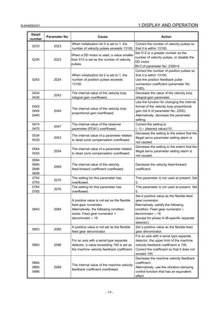
Details of invalid FSSB setting alarms
Diagnosis 3510 FSSB alarm number
[Data type] Word
Information is output for identifying the location (parameter) and cause of an
FSSB-related alarm which has been issued. For the displayed detail numbers and
corresponding causes and actions, see the table below. When multiple FSSB alarm
numbers appear, address the alarms in ascending order of the FSSB alarm number.
- 35 -](https://image.slidesharecdn.com/b-64485en01-121129013453-phpapp02/85/B-64485-en-01-57-320.jpg)

![B-64485EN/01 1.DISPLAY AND OPERATION
Diagnosis 3511 FSSB alarm number
[Data type] Word axis
Information is output for identifying the location (parameter) and cause of an
FSSB-related alarm which has been issued. For the displayed detail numbers and
corresponding causes and actions, see the table below. When multiple FSSB alarm
numbers appear, address the alarms in ascending order of the FSSB alarm number.
Detail Parameter
Cause Action
alarm No. number
Although a separate detector is not Set parameter Nos. 24096 to 24103 to
210 24096 to 24103 set, a value is set in parameter No. all 0.
24096 to 24103.
An unavailable servo axis number is Change the servo axis number.
220 1023
set.
A servo axis number is set more than Change the servo axis number.
221 1023
once.
For a specific servo axis, two or more To use two separate detectors for a
separate detectors are used and the specific servo axis, one separate
paired separate detectors are two of detector must have an odd number and
250 24096 to 24103
the first, third, fifth, and seventh units the other must have an even number.
or the second, fourth, sixth, and eighth Three or more separate detectors
units. cannot be used.
・ The servo axis number Check the conditions on the left.
corresponding to the ATR value
setting is not set for parameter No.
1023 1023.
270
24000 to 24095 ・ An unavailable servo axis number is
set.
・ A servo axis number is set more
than once.
For an FSSB line of servo HRV3 For the FSSB line of servo HRV3
control, only the following servo axis control, set the servo axis numbers on
1023
292 numbers can be used: the left.
2013#0
(1 + 8n, 2 + 8n, 3 + 8n, 4 + 8n (n = 0,
1, …, 9))
For an FSSB line of servo HRV4 For the FSSB line of servo HRV4
1023 control, only the following servo axis control, set the servo axis numbers on
294
2014#0 numbers can be used: the left.
(1+8n(n=0,1,…,9))
311 24096 to 24103 A connector number is invalid. Specify a value between 0 and 8.
A connector number is set more than Make setting so that each connector
314 24096 to 24103 once. number is used only once for one
separate detector.
2013#0 Different current loops (HRV) are Set the same current loop (HRV) for the
350
2014#0 used for FSSB lines. FSSB lines.
Different current loops (HRV) are set Set servo axis numbers so that each set
1023
for the first and second FSSB lines of (1 to 6), (9 to 14), (17 to 22), (25 to
360 2013#0
and parameter No. 1023 setting is 30), (33 to 38), and (41 to 46) is set for
2014#0
invalid. the same FSSB line.
1902#0 When servo HRV3 or HRV4 control is To set servo HRV3 or HRV4 control,
1902#1 set, manual setting 1 cannot be perform manual setting or automatic
370
2013#0 performed. setting.
2014#0
When a servo axis number is skipped, Set servo axis numbers without skipping
380 1023 manual setting 1 cannot be any number.
performed.
- 37 -](https://image.slidesharecdn.com/b-64485en01-121129013453-phpapp02/85/B-64485-en-01-59-320.jpg)
![1.DISPLAY AND OPERATION B-64485EN/01
Detail Parameter
Cause Action
alarm No. number
An attempt was made to perform Reduce the number of connected servo
manual setting 1 though the maximum axes to the maximum number of
382 1023
number of controlled axes per FSSB controlled axes or less.
line is exceeded.
470 24000 to 24095 An ATR value is set more than once. Set each ATR value only once.
A servo axis number is inconsistent Check whether the value set in
with the ATR value setting or the parameter No. 1023 is consistent with
1023
481 servo motor having a servo axis ATR value setting and whether the servo
24000 to 24095
number is not connected. motor corresponding to each servo axis
number is connected.
At power-on, amplifier ID information Check the connection between the CNC
520 2165 could not be read. and each amplifier.
Alternatively, an amplifier may be faulty.
The ATR value setting is inconsistent Make the value set in parameter No.
1023
550 with the servo axis number setting. 1023 consistent with the ATR value
24000 to 24095
setting.
The number of ATR value settings Make as many settings as the number of
551 24000 to 24095 exceeds the number of slaves slaves connected to the CNC.
connected to the CNC.
An unavailable servo axis number is Change the servo axis number.
552 1023
set.
A servo axis number is set more than Change the servo axis number.
553 1023
once.
A value is set in parameter No. 24096 Set parameters Nos. 24096 to 24103 to
554 24096 to 24103 to 24103 though no separate detector all 0.
is connected.
555 The maximum current of an amplifier Set the maximum current of the amplifier
557 2165 (parameter No. 2165) differs from that (parameter No. 2165) to that of the
558 of a motor. motor.
1023 1023 An invalid servo axis number is set. Set a correct servo axis number.
Diagnosis 3513 FSSB alarm number
[Data type] Word spindle
Information is output for identifying the location (parameter) and cause of an
FSSB-related alarm which has been issued.
For the displayed detail numbers and corresponding causes and actions, see the table
below. When multiple FSSB alarm numbers appear, address the alarms in ascending
order of the FSSB alarm number.
Detail Parameter
Cause Action
alarm No. number
3717 An ATR value is set more than once. Make each spindle amplifier consistent
271
24000 to 24095 with the ATR value setting.
When a spindle amplifier number is Set spindle amplifier numbers without
381 3717 skipped, manual setting 1 cannot be skipping any number.
performed.
Diagnosis data related to linear scale with absolute address reference marks
Diagnosis 3545 Linear scale with absolute address reference marks: Measurement point 1
Diagnosis 3546 Linear scale with absolute address reference marks: Measurement point 2
Diagnosis 3547 Linear scale with absolute address reference marks: Measurement point 3
- 38 -](https://image.slidesharecdn.com/b-64485en01-121129013453-phpapp02/85/B-64485-en-01-60-320.jpg)
![B-64485EN/01 1.DISPLAY AND OPERATION
Diagnosis 3548 Linear scale with absolute address reference marks: Measurement point 4
[Data type] 2-word axis
[Unit of data] Detection unit
[Valid data range] -999999999 to 999999999
Diagnosis 3549 Linear scale with absolute address reference marks: Status display
Diagnosis 3550 Linear scale with absolute address reference marks: Scale value
[Data type] 2-word axis
[Unit of data] Detection unit
[Valid data range] -999999999 to 999999999
Diagnosis 3551 Linear scale with absolute address reference marks: Scale value (High)
[Data type] 2-word axis
[Unit of data] Detection unit
[Valid data range] -999 to 999
Linear scale with absolute address reference marks
Scale value = Diagnosis No.3551 × 1,000,000,000 + Diagnosis No.3550
Wrong operation prevention function
#7 #6 #5 #4 #3 #2 #1 #0
Diagnosis 3570 MSC
[Data type] Bit path
#0 MSC Memory operation is stopped due to the reconfirming of midway block start.
In a multipath system, the bit is set to 1 on only the path on which the cursor is position in
the middle of the program.
Diagnosis data related to flexible path axis assignment
Diagnosis 4000 Reason number of alarm in flexible path axis assignment
The cause of the alarm that may be issued in flexible path axis assignment is displayed.
1 The number of axes in the path is 0.
2 The number of axes in the path is larger than its allowable maximum value.
3 The removal command has no ID specification.
4 The removal command has a duplicate ID specification.
5 An axis specified with removal command P does not exist in the path or has been
removed from the path.
6 An axis specified with removal command Q does not exist in the path or has been
removed from the path.
7 An axis specified with removal command R does not exist in the path or has been
removed from the path.
8 An axis specified with the removal command does not exist in the path or has been
removed from the path.
9 The removal command has no axis specification or has an ID specification.
10 In flexible path axis assignment, the ID specification is incorrect.
11 The assignment command has no ID specification.
12 The assignment command has a duplicate ID specification.
13 The assignment command has a duplicate axis arrangement specification.
14 The path specified with the arrangement command has no target axis or the
arrangement command has no ID specification.
15 The path specified with the arrangement command has an invalid axis assignment
specification.
- 39 -](https://image.slidesharecdn.com/b-64485en01-121129013453-phpapp02/85/B-64485-en-01-61-320.jpg)

![B-64485EN/01 1.DISPLAY AND OPERATION
Diagnosis 4001 Belonging path of axis in flexible path axis assignment
A path (specified by parameter No. 981) to which an axis specified for flexible path axis
assignment belongs is displayed.
0 : Source path
1 to 10 : Destination path (because of assignment or exchange)
-1 to -10 : Already removed
Pulse superimposed function
Diagnosis 4110 Number of accumulated pulses specified by the pulse superimposed function
[Data type] Floating point number axis
[Unit of data] Input unit
The number of accumulated pulses specified by pulse superimposition is indicated. The
number multiplied by the travel distance magnification is indicated.
Diagnosis 4110 Number of accumulated pulses specified by the pulse superimposed function
[Data type] Floating point number axis
[Unit of data] Input unit
When the maximum cutting feedrate is to be exceeded by the specified pulse
superimposition, the pulses exceeding the allowable number (set in parameter No. 7117)
are discarded.
This diagnosis data indicates the number of accumulated pulses that are actually
discarded in pulse superimposition.
| Number of pulses specified by pulse superimposition × travel distance magnification | >
|maximum cutting feedrate + allowable number of pulses |
→ Number of discarded pulses
= Number of pulses specified by pulse superimposition × travel distance magnification -
maximum cutting feedrate - allowable number of pulses
| Number of pulses specified by pulse superimposition × travel distance magnification | <
|maximum cutting feedrate + allowable number of pulses |
→ Number of discarded pulses = 0
NOTE
When the pulse superimposed function is disabled (bit 0 (PSI) of
parameter No. 10350 is set to 0), reset operation clears the
indicated number of accumulated/discarded pulses.
Total of the current actual power consumption of all servo axes/spindles
Diagnosis 4900 Total of current actual power consumption of all axes
[Data type] 2-word
[Unit of data] W
NOTE
The actual power consumption is obtained by subtracting the
regenerative power from the power consumption. If the
regenerative power exceeds the power consumption, the actual
power consumption becomes a negative value.
Current actual power consumption of each servo axis
Diagnosis 4901 Current actual power consumption of each servo axis
[Data type] 2-word axis
- 41 -](https://image.slidesharecdn.com/b-64485en01-121129013453-phpapp02/85/B-64485-en-01-63-320.jpg)
![1.DISPLAY AND OPERATION B-64485EN/01
[Unit of data] W
NOTE
This power consumption becomes a negative value during
regeneration of power such as reduction in servo axis speed.
Current actual power consumption of each spindle
Diagnosis 4902 Current actual power consumption of each spindle
[Data type] 2-word spindle
[Unit of data] W
NOTE
This power consumption becomes a negative value during
regeneration of power such as reduction in spindle speed.
Accumulated value of the total power consumption of all servo axes/spindles
Diagnosis 4910 Accumulated value of the total actual power consumption of all axes
Diagnosis 4911 Accumulated value of the total power consumption of all axes
Diagnosis 4912 Accumulated value of the total regenerated power of all axes
[Data type] 2-word
[Unit of data] 0.001kWh
NOTE
These values are accumulated after power-on.
Accumulated value of power consumption of each servo axis
Diagnosis 4920 Accumulated value of the actual power consumption of each servo axis
Diagnosis 4921 Accumulated value of the power consumption of each servo axis
Diagnosis 4922 Accumulated value of the regenerated power of each servo axis
[Data type] 2-word axis
[Unit of data] 0.001kWh
NOTE
These values are accumulated after power-on.
Accumulated value of power consumption of each spindle
Diagnosis 4930 Accumulated value of the actual power consumption of each spindle
Diagnosis 4931 Accumulated value of the power consumption of each spindle
Diagnosis 4932 Accumulated value of the regenerated power of each spindle
[Data type] 2-word spindle
[Unit of data] W
NOTE
These values are accumulated after power-on.
- 42 -](https://image.slidesharecdn.com/b-64485en01-121129013453-phpapp02/85/B-64485-en-01-64-320.jpg)
![B-64485EN/01 1.DISPLAY AND OPERATION
Interpolation state
Diagnosis 5000 Smoothing mode
[Data type] Bit
NAME Interpolation state when "1" is indicated
Smooth IPL on When smooth interpolation G5.1 Q2 is specified and all conditions are satisfied, "1" is
indicated. The G5.1 Q2 command turns on AI contour control at the same time. Therefore,
the AI contour control mode signal AICC<Fn062.0> turns on and AICC1/AICC2 blinks
in the state display at the lower right of the screen.
SMOOTHING ON When nano smoothing G5.1 Q3 is specified and all conditions are satisfied, "1" is
indicated. The G5.1 Q3 command turns on AI contour control at the same time. Therefore,
the AI contour control mode signal AICC<Fn062.0> turns on and AICC1/AICC2 blinks
in the state display at the lower right of the screen.
3-dimensional machine position compensation
Diagnosis 5302 Compensation amount of 3-dimensional machine position compensation
[Data type] 2-word axis
[Unit of data] Detection unit
The compensation value of 3-dimensional machine position compensation is indicated.
Diagnosis data related to automatic phase synchronization for flexible
synchronous control
Diagnosis 5600 Error of automatic phase synchronization (group A)
Diagnosis 5601 Error of automatic phase synchronization (group B)
Diagnosis 5602 Error of automatic phase synchronization (group C)
Diagnosis 5603 Error of automatic phase synchronization (group D)
[Data type] Real path
[Unit of data] mm, inch, deg (machine unit)
Error between master axis and slave axis after executing automatic phase Synchronization
for flexible synchronous control is displayed.
This data is displayed in the path of slave axis in inter-path flexible synchronous control.
Diagnosis 5604 Maximum error of Automatic Phase Synchronization (group A)
Diagnosis 5605 Maximum error of Automatic Phase Synchronization (group B)
Diagnosis 5606 Maximum error of Automatic Phase Synchronization (group C)
Diagnosis 5607 Maximum error of Automatic Phase Synchronization (group D)
[Data type] Real path
[Unit of data] mm, inch, deg (machine unit)
Maximum error between master axis and slave axis after executing automatic phase
synchronization for flexible synchronous control is displayed.
This data is displayed in the path of slave axis in inter-path flexible synchronous control.
This data is cleared when automatic operation is started in auto mode.
This data is cleared when flexible synchronous control is started in manual mode.
- 43 -](https://image.slidesharecdn.com/b-64485en01-121129013453-phpapp02/85/B-64485-en-01-65-320.jpg)


![1.DISPLAY AND OPERATION B-64485EN/01
Example 1)
When a parameter is entered
Example 2)
When a parameter is entered
Example 3)
When a parameter is output to an external input/output device
(10) Tool post name
The number of a path whose status is indicated is displayed.
PATH1 : Indicates that the status being indicated is for path 1.
Other names can be used depending on the settings of parameters 3141 to 3147.
The tool post name is displayed at the position where (8) is now displayed.
While the program is edited, (8) is displayed.
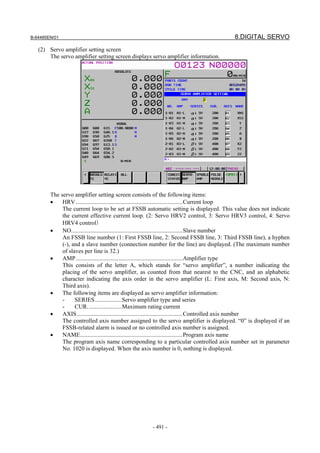
1.5 OPERATING MONITOR
Load meter of the servo axis and the serial spindle and the speed meter can be displayed.
1.5.1 Display Method
1 Set a parameter to display operating monitor. (Bit 5 (OPM) of parameter No.3111)
2 Press the key to display the position display screen.
3 Press continuous menu key , then soft key [MONITOR] is displayed.
4 Press the soft key [MONITOR], then the operating monitor screen is displayed.
- 46 -](https://image.slidesharecdn.com/b-64485en01-121129013453-phpapp02/85/B-64485-en-01-68-320.jpg)
![B-64485EN/01 1.DISPLAY AND OPERATION
CAUTION
1 The bar graph for the load meter shows load up to 200%.
2 The bar graph for the speed meter shows the ratio of the current spindle speed
to the maximum spindle speed (100%). Although the speed meter normally
indicates the speed of the spindle motor, it can also be used to indicate the
speed of the spindle by setting bit 6 (OPS) of parameter 3111 to 1.
3 The servo axes for their load meters are displayed are set to parameter No.
3151 to 3153. If parameters 3151 to 3153 are all zero, the load meter of the
basic axes are displayed.
4 When high precision spindle speed control is enabled, these values are rounded
off to nearest integers.
1.5.2 Parameters
#7 #6 #5 #4 #3 #2 #1 #0
3111 OPS OPM
[Input type] Setting input
[Data type] Bit path
#5 OPM Operating monitor
0: Not displayed
1: Displayed
#6 OPS The speedometer on the operating monitor screen indicates:
0: Spindle motor speed
1: Spindle speed
- 47 -](https://image.slidesharecdn.com/b-64485en01-121129013453-phpapp02/85/B-64485-en-01-69-320.jpg)
![1.DISPLAY AND OPERATION B-64485EN/01
1.6 WAVEFORM DIAGNOSIS DISPLAY
The waveform diagnosis display function traces values of data such as servo positional deviation amount,
torque, and machine signals and plots and displays a graph representing changes in the traced data. This
function facilitates servo motor and spindle motor adjustment and fault location when trouble has
occurred.
The waveform diagnosis function can trace the following data:
(1) Servo-related data
• Positional deviation amount
• Pulse amount after distribution
• Torque amount (actual current)
• Pulse amount after acceleration/deceleration
• Current command value
• Heat simulation data
• Composite speed of all axes
(2) Spindle-related data
• Speed of each spindle
• Load meter value
• Difference in spindle-converted positional deviation during rigid tapping
(3) Machine signal
• ON/OFF state of the external I/O signal specified by a signal address
Up to four servo and spindle data items or up to 32 signals can be traced at the same time.
Data can be traced under the following three conditions:
(1) Data is acquired at any point of time.
(2) Data immediately after a specified event is acquired.
(3) Data immediately before a specified event is acquired.
In condition (1), the time to end tracing can be delayed by a specified time. This allows data before and
after the occurrence of an event can be acquired.
Traced data can be output to an external input/output device.
1.6.1 Waveform Diagnosis Graph Screen
1 Press the function key .
2 Pressing the soft key [W.DGNS] displays a screen as shown below.
3 Pressing the operation soft key [(OPRT)] displays the following soft keys:
- 48 -](https://image.slidesharecdn.com/b-64485en01-121129013453-phpapp02/85/B-64485-en-01-70-320.jpg)
![B-64485EN/01 1.DISPLAY AND OPERATION
- Servo and spindle data
Each waveform is drawn in a specified color. The numbers and colors of the first and second waveforms
are indicated in the upper left part, and the numbers and colors of the third and fourth waveforms are
indicated in the upper right part.
- I/O signals
When displayed over the waveforms of servo and spindle data, up to four I/O signals are plotted in the
lower half of the screen.
In this case, the addresses of the plotted signals are indicated in the second column on the left side.
When only signal data is displayed, up to nine signals are plotted in the entire screen.
The addresses of the plotted signals are indicated in the first column on the left side.
1.6.2 Waveform Diagnosis Parameter Screen
Display
1 Press the function key .
2 Press the soft key [W.DGNS].
3 Pressing the soft key [PARAME] displays the waveform diagnosis parameter screen.
- 49 -](https://image.slidesharecdn.com/b-64485en01-121129013453-phpapp02/85/B-64485-en-01-71-320.jpg)
![1.DISPLAY AND OPERATION B-64485EN/01
Editing
1 Follow the steps explained in "Display" to display the screen.
2 Pressing the cursor keys moves the cursor on the screen.
3 Press numeric keys, then press the MDI key or soft key [INPUT] to set the entered value.
4 Press the [(OPRT)] operation soft key to display the following operation soft keys:
Pressing continuous menu key displays the following soft keys:
Pressing [TRACE] displays the trace setting screen of the waveform diagnosis parameter screen.
Pressing [WAVE] displays the waveform setting screen of the waveform diagnosis parameter screen.
- 50 -](https://image.slidesharecdn.com/b-64485en01-121129013453-phpapp02/85/B-64485-en-01-72-320.jpg)
![B-64485EN/01 1.DISPLAY AND OPERATION
Pressing [SIGNAL] displays the signal setting screen of the waveform diagnosis parameter screen.
Trace setting
- Trace condition
One of the following three trace conditions can be selected to start and end tracing:
Type 1 (1: JUST)
Data is traced only for a specified period of time immediately after the soft key [TRACE] is pressed.
Trace time
Time
[TRACE] pressed
Type 2 (2: AFTER)
When the soft key [TRACE] has been pressed, data is traced only for a specified period of time
immediately after a specified trigger event occurs.
Trace time
Time
[TRACE] pressed Event occurs
Type 3 (3: BEFORE)
When the soft key [TRACE] has been pressed, data is traced only for a specified period of time
immediately before a specified trigger event occurs.
Trace time
Time
[TRACE] pressed Event occurs
Setting Trace condition
1 Type 1
2 Type 2
3 Type 3
- 51 -](https://image.slidesharecdn.com/b-64485en01-121129013453-phpapp02/85/B-64485-en-01-73-320.jpg)


![B-64485EN/01 1.DISPLAY AND OPERATION
As shown in the above example, set a PMC path number plus a colon (:) plus an address. With the
standard PMC, which has just one path, no path number needs to be specified.
NOTE
1 For PMC path numbers, refer to "Multi-Path PMC Function" in "PMC
Programming Manual" (B-64513EN).
2 If the keyboard used does not have the ":" key, use ";" or "/" instead of ":".
3 For signal data, even when just one signal address is input in an address 1 to
32, one channel is used.
4 When tracing is not performed, enter 0.
5 Up to 32 signals can be measured at the same time.
Guide to selecting items
- Alarm type
1 When the soft key [(OPRT)] is pressed with the cursor positioned at the alarm type in the trigger
setting, the soft key [EXPLAIN] appears.
2 Pressing the soft key [EXPLAIN] displays a list of alarm types.
- Data type
1 When the soft key [(OPRT)] is pressed with the cursor positioned at the trace data type in the trace
waveform setting, the soft key [EXPLAIN] appears.
2 Pressing the soft key [EXPLAIN] displays a list of trace data types.
- 57 -](https://image.slidesharecdn.com/b-64485en01-121129013453-phpapp02/85/B-64485-en-01-79-320.jpg)
![1.DISPLAY AND OPERATION B-64485EN/01
- Waveform color
1 When the soft key [(OPRT)] is pressed with the cursor positioned at the waveform color in the trace
waveform setting, the soft key [EXPLAIN] appears.
2 Pressing the soft key [EXPLAIN] displays a list of waveform colors
1.6.3 Tracing Data
Starting tracing
1 Display the waveform diagnosis graph screen.
2 Press the soft key [TRACE] to start tracing.
"Now Sampling…" appears in the upper part of the screen. When tracing ends, the indication "Now
Sampling…" disappears.
Even when the screen display is changed to another screen, tracing continues.
Canceling tracing
When the soft key [CANCEL] is pressed during tracing, tracing stops.
- 58 -](https://image.slidesharecdn.com/b-64485en01-121129013453-phpapp02/85/B-64485-en-01-80-320.jpg)
![B-64485EN/01 1.DISPLAY AND OPERATION
Moving, extending, and reducing a waveform
When soft key [H-DOBL] or [H-HALF] is pressed, the length of the time axis on one screen is extended
or reduced, respectively.
When a waveform cannot fit in one screen, the time axis can be moved by pressing soft key [←TIME] or
[TIME→].
Furthermore, pressing [CH-1], [CH-2], [CH-3], or [CH-4], a submenu appears.
When soft key [WAVE.EX] or [WAVE.RE] is pressed, the length of the time axis on one screen is
extended or reduced, respectively. The graduation unit on the horizontal axis, which is a parameter, also
changes automatically.
The graduation unit changes from 1 to 2 to 5 to 10 to 20 to 50 to 100, and so on.
When soft key [WAVE.↑] or [WAVE.↓] is pressed, each waveform of servo and spindle data can be
moved upward or downward.
Displaying signal data
Up to 32 signals can be measured at the same time. Up to nine signals can be displayed at the same time if
only signal data is displayed, or up to four signals can be displayed if signal data is displayed over
waveforms.
When soft key [SIG.↑] or [SIG.↓] is pressed, the currently displayed signals are changed.
NOTE
Signal data cannot be moved.
1.6.4 Outputting Data
Waveform diagnosis data can be output to an input/output device.
Specifying a format
When outputting data, you can select one of the two formats, which are the FS16i compatible format
(called the 16 compatible format hereinafter) and the FS30i format (called the 30 format hereinafter). If
bit 0 (IOF) of parameter No. 10600 is set to 0, the 30 format is selected; if bit 0 (IOF) of parameter No.
10600 is set to 1, the 16 compatible format is selected.
Output format
Traced data is input or output as a text file with the following format:
- 59 -](https://image.slidesharecdn.com/b-64485en01-121129013453-phpapp02/85/B-64485-en-01-81-320.jpg)


![B-64485EN/01 1.DISPLAY AND OPERATION
- Sample file
T01WAVE DIAGNOSE Header
T69D20040101,120125 Start time
T92D20040101,120130 End time
T90D2 Waveform period
T91D4 Signal period
T68P0D1,2 Measurement item/axis
T68P4D1
T68P10D1
T68P30DG0010.4,G0010.5,G0010.6 Measurement item/signal
T60D643,6420 Waveform data
T64D270
T75D1855
T60D673,6451
T64D265
T75D1855
T60D702,6480
T64D268
T75D1855
:
T75D1855
T98D0,0,1 Signal data
T98D0,0,1
T98D0,0,1
:
Outputting a file
1 Display the waveform diagnosis graph screen.
2 When the [(OPRT)] operation soft key is pressed, soft keys are displayed in the following operation
selection state:
- 63 -](https://image.slidesharecdn.com/b-64485en01-121129013453-phpapp02/85/B-64485-en-01-85-320.jpg)
![1.DISPLAY AND OPERATION B-64485EN/01
3 Change the mode to the EDIT mode.
4 Enter a file name in the key-in buffer, and press the soft key [PUNCH]. If no file name is input, the
file name is assumed to be WAVE-DGN.TXT by default.
5 Press the soft key [EXEC] shown below to start outputting data:
6 When data output ends, or when the soft key [CAN] is pressed, the initial operation selection state is
restored.
NOTE
While data is being traced, data output is not allowed.
Parameter
#7 #6 #5 #4 #3 #2 #1 #0
10600 IOF
[Input type] Parameter input
[Type of data] Bit
#0 IOF The output format used for waveform diagnosis is:
0: 30i /31i /32i format (30 format).
1: 16i /18i /21i format (16 compatible format).
- 64 -](https://image.slidesharecdn.com/b-64485en01-121129013453-phpapp02/85/B-64485-en-01-86-320.jpg)
![B-64485EN/01 1.DISPLAY AND OPERATION
1.7 COLOR SETTING SCREEN
On the color setting screen, the colors of the VGA screen can be set.
1.7.1 Screen Display
1 Press the function key .
2 Press the continuous menu key several times until the soft key [COLOR] is displayed.
3 Pressing the soft key [COLOR] displays the color setting screen.
1.7.2 Operations for Color Setting
Modification to color settings (color palette values)
1 Pressing the soft key [(OPRT)] displays the following operation soft keys:
2 Move the cursor to a color number whose color palette values are to be modified.
The current color palette values of the individual color elements are displayed.
3 Select a color element to be modified, with the soft key [RED], [GREEN], or [BLUE].
Multiple color elements can be selected at a time.
Each of the soft keys [RED], [GREEN], and [BLUE] toggles between selection and deselection each
time the soft key is pressed.
(The soft keys [RED], [GREEN], and [BLUE], when not displayed, can be displayed by pressing the
rightmost soft key.)
4 By pressing the operation soft key [BRIGHT] or [DARK], modify the brightness of the selected
color element.
Storing color settings (color palette values)
Set color palette values can be stored.
- 65 -](https://image.slidesharecdn.com/b-64485en01-121129013453-phpapp02/85/B-64485-en-01-87-320.jpg)
![1.DISPLAY AND OPERATION B-64485EN/01
1 Select a storage area by pressing the [COLOR1], [COLOR2], or [COLOR3] operation soft key.
Color 1 Color 1 (standard color) data parameters Nos. 6581 to 6595
Color 2 Color 2 data parameters Nos. 10421 to 10435
Color 3 Color 3 data parameters Nos. 10461 to 10475
2 Press the operation soft key [STORE]. The following operation soft keys are displayed:
3 Press the operation soft key [EXEC]. The current color palette values are stored in the selected area.
Pressing the operation soft key [CAN] or the leftmost key does not store the current color palette
values.
Calling color settings (color palette values)
1 Select an area for storing color palette values by pressing the operation soft key [COLOR1],
[COLOR2], or [COLOR3].
(The soft keys [COLOR1], [COLOR2], and [COLOR3], when not displayed, can be displayed by
pressing the rightmost soft key.)
2 Press the [RECALL] operation soft key. The following operation soft keys are displayed:
3 Press the operation soft key [EXEC]. Color palette values are called from the selected area for
modification to the color settings. This operation is invalid if no color palette values are stored.
Pressing the operation soft key [CANCEL] or the leftmost key does not call color palette values.
1.7.3 Parameter
6581 RGB value of color palette 1 for color set 1
6582 RGB value of color palette 2 for color set 1
6583 RGB value of color palette 3 for color set 1
6584 RGB value of color palette 4 for color set 1
6585 RGB value of color palette 5 for color set 1
6586 RGB value of color palette 6 for color set 1
6587 RGB value of color palette 7 for color set 1
6588 RGB value of color palette 8 for color set 1
6589 RGB value of color palette 9 for color set 1
6590 RGB value of color palette 10 for color set 1
6591 RGB value of color palette 11 for color set 1
6592 RGB value of color palette 12 for color set 1
6593 RGB value of color palette 13 for color set 1
6594 RGB value of color palette 14 for color set 1
6595 RGB value of color palette 15 for color set 1
- 66 -](https://image.slidesharecdn.com/b-64485en01-121129013453-phpapp02/85/B-64485-en-01-88-320.jpg)
![B-64485EN/01 1.DISPLAY AND OPERATION
[Data type] 2-word
[Unit of data] rrggbb 6-digit number
(rr: Red data, gg: Green data, bb: Blue data)
When a number shorter than 6 digits is specified, the unspecified higher digit or digits are
treated as 0.
[Valid data range] 00 to 15 for each color data (same as the tone level on the color setting screen)
When a value equal to or greater than 16 is specified, the specification of 15 is assumed.
(Example) When setting the color tone level as red = 1, green = 2, and blue = 3, specify "10203".
10421 RGB value of color palette 1 for color set 2
10422 RGB value of color palette 2 for color set 2
10423 RGB value of color palette 3 for color set 2
10424 RGB value of color palette 4 for color set 2
10425 RGB value of color palette 5 for color set 2
10426 RGB value of color palette 6 for color set 2
10427 RGB value of color palette 7 for color set 2
10428 RGB value of color palette 8 for color set 2
10429 RGB value of color palette 9 for color set 2
10430 RGB value of color palette 10 for color set 2
10431 RGB value of color palette 11 for color set 2
10432 RGB value of color palette 12 for color set 2
10433 RGB value of color palette 13 for color set 2
10434 RGB value of color palette 14 for color set 2
10435 RGB value of color palette 15 for color set 2
[Data type] 2-word
[Unit of data] rrggbb 6-digit number
(rr: Red data, gg: Green data, bb: Blue data)
When a number shorter than 6 digits is specified, the unspecified higher digit or digits are
treated as 0.
[Valid data range] 00 to 15 for each color data (same as the tone level on the color setting screen)
When a value equal to or greater than 16 is specified, the specification of 15 is assumed.
(Example) When setting the color tone level as red = 1, green = 2, and blue = 3, specify "10203".
10461 RGB value of color palette 1 for color set 3
10462 RGB value of color palette 2 for color set 3
10463 RGB value of color palette 3 for color set 3
10464 RGB value of color palette 4 for color set 3
10465 RGB value of color palette 5 for color set 3
10466 RGB value of color palette 6 for color set 3
10467 RGB value of color palette 7 for color set 3
10468 RGB value of color palette 8 for color set 3
10469 RGB value of color palette 9 for color set 3
- 67 -](https://image.slidesharecdn.com/b-64485en01-121129013453-phpapp02/85/B-64485-en-01-89-320.jpg)
![1.DISPLAY AND OPERATION B-64485EN/01
10470 RGB value of color palette 10 for color set 3
10471 RGB value of color palette 11 for color set 3
10472 RGB value of color palette 12 for color set 3
10473 RGB value of color palette 13 for color set 3
10474 RGB value of color palette 14 for color set 3
10475 RGB value of color palette 15 for color set 3
[Data type] 2-word
[Unit of data] rrggbb 6-digit number
(rr: Red data, gg: Green data, bb: Blue data)
When a number shorter than 6 digits is specified, the unspecified higher digit or digits are
treated as 0.
[Valid data range] 00 to 15 for each color data (same as the tone level on the color setting screen)
When a value equal to or greater than 16 is specified, the specification of 15 is assumed.
[Example] When setting the color tone level as red = 1, green = 2, and blue = 3, specify "10203".
1.7.4 Notes
(1) Immediately after the power is turned on, color 1 is used as the screen color.
If no color palette values are stored in color 1, the FANUC standard color is used for display.
(2) Do not modify the parameters of the standard color data by direct MDI key input. When modifying
the parameters of the RGB value, be sure to perform a storage operation on the color setting screen.
(3) If the screen display becomes invisible because an incorrect value is input in an RGB value
parameter, turn off the power then turn on the power again while holding down the +
keys. All stored color data is cleared, and the screen is displayed in the FANUC standard color.
This operation, however, clears all contents of the memory including parameters and programs. Take
special care when performing this operation.
1.8 POWER MATE CNC MANAGER FUNCTION
When the I/O Link Option for the FANUC servo unit βi series (called I/O Link βi below) is used for CNC
additional axes (slaves), the Power Mate CNC manager function can be used to display and set up various
types of data of these slaves on the CNC.
The Power Mate CNC manager function enables the following display and setting operations:
(1) Current position display (absolute/machine coordinates)
(2) Parameter display and setting
(3) Alarm display
(4) Diagnosis data display
(5) System configuration screen display
Up to eight slaves can be connected to each I/O Link channel.
- 68 -](https://image.slidesharecdn.com/b-64485en01-121129013453-phpapp02/85/B-64485-en-01-90-320.jpg)
![B-64485EN/01 1.DISPLAY AND OPERATION
1.8.1 Screen Display
1 Press the function key .
2 Press the continuous menu key several times until the soft key [P.MATE MGR.] is displayed.
3 Pressing the soft key [P.MATE MGR.] displays the absolute coordinate screen, which is the initial
screen of the Power Mate CNC manager. On this screen, you can select each of the following items
by pressing the corresponding soft key:
ABS: Absolute coordinate display
MACHIN: Machine coordinate display
PARAM: Parameter screen
MSG: Alarm list
DGNOS: Diagnosis screen
SYSTEM: System information
To select another function after one of the functions listed above is selected, press the return menu
key until the soft keys appear as shown above. Then, select the desired function.
4 Terminating the Power Mate CNC manager function
Press the return menu key once or twice. The soft keys of the CNC system appear, and the Power
Mate CNC manager terminates.
Alternatively, you can select another function by pressing an MDI function key ( , ,
, etc.) to terminate the Power Mate CNC manager function.
Selecting a slave
When slaves are connected to multiple I/O Link channels, pressing soft key [NEXT CH.] or [PREV. CH.]
displayed by pressing the soft key [(OPRT)] changes the displayed channel.
In the upper section of the screen, the following information items are displayed for the connected slaves
(up to eight slaves):
• I/O Link group number (0 to 15)
• Alarm status
The cursor is positioned at the number of the slave for which to display information (active slave). When
multiple slaves are connected, pressing the soft key [NEXT SLAVE] or [PREV. SLAVE] changes the
active slave.
You can display the slave status and select a slave on any screen of the Power Mate CNC manager
function.
Current position display screen
The current position display screen displays the current position and actual feedrate of the slave.
The following current position data is displayed:
• Absolute coordinate (current position in the absolute coordinate system)
• Machine coordinate (current position in the machine coordinate system)
- Display method
Press soft key [ABS] or [MACHIN] to display the absolute coordinate screen or machine coordinate
screen, respectively.
- 69 -](https://image.slidesharecdn.com/b-64485en01-121129013453-phpapp02/85/B-64485-en-01-91-320.jpg)
![1.DISPLAY AND OPERATION B-64485EN/01
Power Mate CNC manager: Machine coordinate screen
Axis name display
You can change the axis name by setting it in the I/O Link βi parameters Nos. 0024 and 0025. Up to two
characters can be set. (Use the ASCII codes of 0 to 9 and/or A to Z). When no axis name is set or the
setting data is invalid, the axis name is set to 1.
This axis name is used only for position display of the Power Mate CNC manager function and irrelevant
to the controlled axis on the CNC.
Parameter screen
The parameters required for the functions of the slave must be specified in advance.
Press soft key [PARAM] to display the parameter screen.
This screen displays only the bit and decimal data. For details of the parameters, refer to FANUC SERVO
MOTOR βi series I/O Link Option Maintenance Manual.
- 70 -](https://image.slidesharecdn.com/b-64485en01-121129013453-phpapp02/85/B-64485-en-01-92-320.jpg)
![B-64485EN/01 1.DISPLAY AND OPERATION
• Selecting and searching for a parameter
1 First, select the active slave.
2 Press the soft key [(OPRT)]. The following soft keys appear:
3 Enter a parameter number and press the soft key [NO. SRH]. The search starts.
You can also select a desired parameter number by pressing the cursor keys
and page keys and moving the cursor.
• Setting a parameter
You can directly set an I/O Link βi parameter of the slave from the CNC.
1 Select a desired parameter using either of the above methods.
2 Press the soft key [(OPRT)]. The following soft keys appear:
3 Enter setting data.
4 Press the soft key [INPUT] or MDI key .
Alarm screen
If an alarm is issued for the slave, “ALARM” is displayed in the slave status field in the upper section of
the screen.
At this time, you can display the alarm screen to check the details of the alarm.
Up to 40 alarm codes are displayed on the screen.
For details of the alarms, refer to FANUC SERVO MOTOR βi series I/O Link Option Maintenance
Manual.
- Display method
Press the soft key [MSG]. On the screen, only error codes are displayed.
Example of displaying alarms for I/O Link βi of slave 0
- 71 -](https://image.slidesharecdn.com/b-64485en01-121129013453-phpapp02/85/B-64485-en-01-93-320.jpg)
![1.DISPLAY AND OPERATION B-64485EN/01
Diagnosis screen
The diagnosis screen displays diagnosis information of the slave.
Diagnosis data is displayed in bit or integer (decimal) representation. For details of diagnosis data, refer
to FANUC SERVO MOTOR βi series I/O Link Option Maintenance Manual.
- Display method
1 Press the continuous menu key .
2 Press soft key [DGNOS] to display the diagnosis screen.
Searching for diagnosis data
1 First, select the active slave.
2 Press the soft key [(OPRT)]. The following soft keys appear:
3 Enter a diagnosis number and press the soft key [NO. SRH]. The search starts.
You can also select a desired parameter number by pressing the cursor keys and page
keys and moving the cursor.
System configuration screen
The system configuration screen displays information on the system software of slaves.
- Display method
1 Press the continuous menu key .
2 Press the soft key [SYSTEM] to select the system configuration screen.
- 72 -](https://image.slidesharecdn.com/b-64485en01-121129013453-phpapp02/85/B-64485-en-01-94-320.jpg)
![B-64485EN/01 1.DISPLAY AND OPERATION
Series and edition of the I/O Link βi system software
1.8.2 Inputting and Outputting Parameters
Outputting parameters
Parameters are output to the CNC memory or a memory card as a data file in the program format. Set the
first registration program number in parameter No. 8760. For each slave, program with a predetermined
number is created.
When parameters are output to the CNC memory, a program with the specified program number is
created.
When parameters are output to a memory card, a file is created, of which file name consists of the
specified program number and an extension PMM.
Program number = setting-of-parameter (parameter No. 8760) + (m - 1) × 100 + n × 10
m: Channel number (1 to 4)
n: Group number
Example: When parameter No. 8760 is set to 8000
Channel 1 (I/O Link β: Group 0)
8000 + 0*100 + 0*10 = 8000
Channel 2 (I/O Link β: Group 1)
8000 + 1*100 + 1*10 = 8110
Channel 3 (I/O Link β: Group 2)
8000 + 2*100 + 2*10 = 8220
Channel 4 (I/O Link β: Group 3)
8000 + 3*100 + 3*10 = 8330
The group number is the slave number displayed in the slave status field in the upper section of the screen
in reverse video.
When bit 3 (PMO) of parameter No. 0961 is set to 1, the numbers of the parameters to be output can be
set only with a group number.
Select a desired input device using bits 1 (MD1) and 2 (MD2) of parameter No. 0960.
Connect a memory card or check the unused area of the CNC memory, then follow the steps below:
1 For multi-path control, display the Power Mate CNC manager screen from the screen for path 1.
2 Select the active slave.
Press the soft key [(OPRT)]. The following soft keys appear:
- 73 -](https://image.slidesharecdn.com/b-64485en01-121129013453-phpapp02/85/B-64485-en-01-95-320.jpg)
![1.DISPLAY AND OPERATION B-64485EN/01
3 Press the soft key [READ]. The following soft keys appear:
4 Press the soft key [EXEC].
During input, “INPUT” blinks in the message field.
NOTE
1 Parameters can be saved in other than the MEM mode or in the emergency stop
status.
2 To save parameters in a memory card, if a file with the same name is found in
the memory card, the parameters cannot be saved. Delete the file from the
memory card or change the file name by setting parameter No. 8760.
To save parameters in a program area, save operation is performed according to
the setting of bit 2 (REP) of parameter No. 3201.
Inputting parameters
A data file of parameters output to the CNC memory or a memory card as a program is input to the slave
determined by the program number. The program number and memory device are determined as
described in “Outputting parameters.”
1 For multi-path control, display the Power Mate CNC manager screen from the screen for path 1.
2 Select the active slave.
3 Press the soft key [(OPRT)]. The following soft keys appear:
4 Press the soft key [PUNCH]. The following soft keys appear:
5 Press the soft key [EXEC].
During output, “OUTPUT” blinks in the message field.
NOTE
1 Parameters can be input in other than the MEM mode or in the emergency stop
status.
2 For multi-path control, parameters can be input and output only using the Power
Mate CNC manager screen for path 1. They can only be input from and output to
the CNC memory for path 1.
1.8.3 Parameters
#7 #6 #5 #4 #3 #2 #1 #0
0960 PPE PMN MD2 MD1
[Input type] Setting input
[Data type] Bit path
- 74 -](https://image.slidesharecdn.com/b-64485en01-121129013453-phpapp02/85/B-64485-en-01-96-320.jpg)
![B-64485EN/01 1.DISPLAY AND OPERATION
#1 MD1
#2 MD2 The slave parameters are input from and output to either of the following devices:
Parameter MD2 Parameter MD1 I/O destination
0 0 Program memory
0 1 Memory card
#3 PMN The Power Mate CNC manager function is:
0: Enabled.
1: Disabled. (Communication with the slave is not performed.)
#4 PPE Setting slave parameters using the Power Mate CNC manager:
0: Can always be performed regardless of the setting of PWE.
1: Follows the setting of PWE.
#7 #6 #5 #4 #3 #2 #1 #0
0961 PMO
[Input type] Parameter input
[Data type] Bit
#3 PMO The O number of a program for saving and restoring the I/O LINK β parameter is set
based on:
0: Group number and channel number
1: Group number only
8760 Program number of data input/output (Power Mate CNC manager)
[Input type] Setting input
[Data type] 2-word path
[Valid data range] 0 to 99999999
This parameter sets the program numbers of programs to be used for inputting and
outputting slave data (parameters) when the Power Mate CNC manager function is used.
For a slave specified with I/O LINK channel m and group n, the following program
number is used:
Setting + (m - 1) × 100 + n × 10
If the setting is 0, the parameters of the slave specified with channel 1 and group 0 cannot
be input from or output to the CNC memory because the program number is set to 0. The
parameters can be input from and output to a memory card.
(Set a value with which any used program number does not exceed 99999999.)
Warning
If an alarm is issued for the Power Mate CNC manager, a warning message is displayed.
Message Description
DATA ERROR An attempt was made to execute [PUNCH] (NC → β) for a program not found in
the program area.
WRITE PROTECTED An attempt was made to execute [READ] (β → NC) for a program area when the
memory protection signal (KEY) is off.
- 75 -](https://image.slidesharecdn.com/b-64485en01-121129013453-phpapp02/85/B-64485-en-01-97-320.jpg)
![1.DISPLAY AND OPERATION B-64485EN/01
Message Description
EDIT REJECTED An attempt was made to execute [READ] (β → NC) when the program area already
contained a program with the same name as that to be created by executing
[READ] (β → NC).
An attempt was made to execute [READ] (β → NC) when the number of the
program to be created by executing [READ] (β → NC) was selected.
An attempt was made to execute [READ] (β → NC) when bit 0 (TVC) of CNC
parameter No. 0000 was set to 1. (Parameters Nos. 0000 to 0019 are output, but
parameter No. 0020 and subsequent parameters are not output.)
An attempt was made to execute [PUNCH] (NC → β) when a memory card did not
contain any program for which [PUNCH] (NC → β) could be executed.
An attempt was made to execute [READ] (β → NC) for a protected memory card.
NO MORE SPACE An attempt was made to execute [READ] (β → NC) when the program area did not
have enough unused space.
FORMAT ERROR Data other than digits, signs, CAN, and INPUT was entered as the setting of a
parameter.
TOO MANY FIGURES Data consisting of 9 or more digits was entered for a bit-type parameter.
DATA IS OUT OF RANGE The setting exceeds the valid data range.
1.8.4 Notes
- Connecting an I/O Link
When I/O Link βi is used as a slave of an I/O Link, the CNC assigns I/O addresses. The slave data is
input and output in 16-byte units. Therefore, be sure to specify 128 as the number of input/output points.
Up to eight slaves can be connected.
The module name is OC021 (16-bit input) or OC020 (16-byte output).
BASE is always 0 and SLOT is always 1.
- Function of ignoring the Power Mate CNC manager
After setting and checking data required for each slave connected, you can stop communication with the
Power Mate CNC manager function to send a command from the CNC ladder to the slave.
When bit 3 (PMN) of parameter No. 960 is set to 1, communication between the CNC and the slave via
the I/O Link is all open to the ladder. While this bit is 1, the Power Mate CNC manager function does not
operate.
- Data protection key
When the program data protection key of the CNC is on, no parameters can be input to the CNC program
memory.
- 76 -](https://image.slidesharecdn.com/b-64485en01-121129013453-phpapp02/85/B-64485-en-01-98-320.jpg)

![1.DISPLAY AND OPERATION B-64485EN/01
In the remainder of this chapter, the term channel (CH) is used to refer to a specific set of measurement
data and the term draw to refer to a specific displayed wave.
CH1 : Measurement data 1
Draw3 : Display waveform 3
A conceptual diagram of the wave display is shown Fig. 1.9 (b).
Measurement data Display data
Operation
CH1 Draw1
Data
CH2 Draw2 Screen
acquisition display
CH3 Draw3
CH4 Draw4
Fig. 1.9 (b)
Measurements of both the servo motor and spindle motor can be made for up to four channels
simultaneously. Also, data can be measured at up to 10000 points per measurement item.
The following five drawing modes are available.
1 Y-time graph
This mode displays wave data along the time axis, as by an oscilloscope.
2 XY graph
This mode provides a 2-dimensional path display using 2-axis data.
3 Circle graph
This mode displays an enlarged view of the path deviation from the specified circle arising during
circular cutting.
4 Fourier graph
This mode displays the frequency spectrum by performing digital Fourier conversion for the range
of data displayed by the Y-time graph.
5 Bode graph
This mode displays a Bode diagram in the form of single logarithm graph for the horizontal axis.
Note
- Axis number
NOTE
For multi-axis control, the axis number must be an absolute axis number instead
of a relative axis number in each path.
1.9.1.1 Y-time graph
The Y-time graph displays wave data for the measurement data along the time axis, as by an oscilloscope.
Up to four draws can be displayed at a time.
Displaying and setting the Y-time graph
Procedure
The procedure for displaying the measurement data is described below.
1 Press the function key.
2 Press the continuous menu key several times until [SERVO GUIDE MATE] is displayed.
3 Click the soft key [SERVO GUIDE MATE].
4 Click the soft key [Y-TIME].
The wave display screen is displayed as shown Fig. 1.9.1.1 (a).
- 78 -](https://image.slidesharecdn.com/b-64485en01-121129013453-phpapp02/85/B-64485-en-01-100-320.jpg)
![B-64485EN/01 1.DISPLAY AND OPERATION
Fig. 1.9.1.1 (a)
5 Click the soft key[MEASUREMENT].
6 Click the soft key[DATA IN].
7 Click the soft key[SAMPLING].
The data-in screen is displayed as shown Fig. 1.9.1.1 (b).
Fig. 1.9.1.1 (b)
8 Move the cursor to the parameter you want to set, by pressing the cursor key.
9 Enter data and then press the key.
10 Repeat steps 8 and 9 until you set all the parameters.
11 Click the soft key [SET CHANNEL].
The channel setting screen is displayed as shown Fig. 1.9.1.1 (c).
To set any channel other than the one currently displayed, display the setting screen for the desired
channel by pressing the or key.
- 79 -](https://image.slidesharecdn.com/b-64485en01-121129013453-phpapp02/85/B-64485-en-01-101-320.jpg)
![1.DISPLAY AND OPERATION B-64485EN/01
Fig. 1.9.1.1 (c)
12 Move the cursor to the parameter you want to set, by pressing the cursor key.
13 Enter data and the press the key.
14 Repeat steps 12 and 13 until you set all the parameters.
15 Click the soft key [RE-DSPGRAPH].
16 Click the soft key [OPERATION & GRAPH].
The operation and graph setting screen is displayed as shown Fig. 1.9.1.1 (d).
To set any draw other than the one currently displayed, display the setting screen for the desired
draw by pressing the or key.
Fig. 1.9.1.1 (d)
17 Move the cursor to the parameter you want to set, by pressing the cursor key.
18 Enter data and the press the key.
19 Repeat steps 17 and 18 until you set all the parameters.
20 Click the soft key [RE-DSPGRAPH].
- 80 -](https://image.slidesharecdn.com/b-64485en01-121129013453-phpapp02/85/B-64485-en-01-102-320.jpg)
![B-64485EN/01 1.DISPLAY AND OPERATION
21 Click the soft key [SCALE SET].
The scale setting screen is displayed as shown Fig. 1.9.1.1 (e).
Fig. 1.9.1.1 (e)
22 Move the cursor to the parameter you want to set, by pressing the cursor key.
23 Enter data and the press the key.
24 Repeat steps 22 and 23 until you set all the parameters.
25 Click the soft key [RE-DSPGRAPH].
26 Click the soft key [MEASUREMENT].
27 Click the soft key [START].
28 Start the automatic or manual operation.
29 When the measurement is completed, the wave display screen is displayed as shown Fig. 1.9.1.1 (f).
Fig. 1.9.1.1 (f)
- Changing the operation and graph setting screen
The procedure for changing the operation and graph setting screen as necessary is described below.
- 81 -](https://image.slidesharecdn.com/b-64485en01-121129013453-phpapp02/85/B-64485-en-01-103-320.jpg)
![1.DISPLAY AND OPERATION B-64485EN/01
1 Click the soft key [OPERATION & GRAPH].
The operation and graph setting screen is displayed as shown Fig. 1.9.1.1 (g).
To set any draw other than the one currently displayed, display the setting screen for the desired
draw by pressing the or key.
Fig. 1.9.1.1 (g)
2 Move the cursor to the parameter you want to set, by pressing the cursor key.
3 Enter data and the press the key.
4 Repeat steps 2 and 3 until you set all the parameters.
5 Click the soft key [RE-DSPGRAPH].
Based on the new operation and graph settings, the wave display screen is displayed as shown Fig.
1.9.1.1 (h).
Fig. 1.9.1.1 (h)
- Changing the scale screen
The procedure for changing the scale settings as necessary is described below.
- 82 -](https://image.slidesharecdn.com/b-64485en01-121129013453-phpapp02/85/B-64485-en-01-104-320.jpg)
![B-64485EN/01 1.DISPLAY AND OPERATION
1 Click the soft key [SCALE SET].
The scale setting screen is displayed as shown Fig. 1.9.1.1 (i).
Fig. 1.9.1.1 (i)
2 Move the cursor to the parameter you want to set, by pressing the cursor key.
3 Enter data and the press the key.
4 Repeat steps 2 and 3 until you set all the parameters.
5 Click the soft key [RE-DSPGRAPH].
Based on the new scale settings, the wave display screen is displayed as shown Fig. 1.9.1.1 (j).
Fig. 1.9.1.1 (j)
- Manipulating the Y-time graph
By clicking the following soft keys, you can perform the operations corresponding to them.
[MEASUREMENT] : Performs a measurement-related operation.
[←] : Shifts the time axis to the right.
[→] : Shifts the time axis to the left.
[H-AXIS EXP] : Expands the time axis.
- 83 -](https://image.slidesharecdn.com/b-64485en01-121129013453-phpapp02/85/B-64485-en-01-105-320.jpg)
![1.DISPLAY AND OPERATION B-64485EN/01
[H-AXIS RED] : Reduces the time axis.
[DRAW 1UNDSP] : Sets whether or not to display Draw 1.
[DRAW 1 ↑] : Shifts Draw 1 downward.
[DRAW 1 ↓] : Shifts Draw 1 upward.
[DRAW 1 V-EXP] : Expands Draw 1.
[DRAW 1 V-RED] : Reduces Draw 1.
[DRAW 2UNDSP] : Sets whether or not to display Draw 2.
[DRAW 2 ↑] : Shifts Draw 2 downward.
[DRAW 2 ↓] : Shifts Draw 2 upward.
[DRAW 2 V-EXP] : Expands Draw 2.
[DRAW 2 V-RED] : Reduces Draw 2.
[DRAW 3UNDSP] : Sets whether or not to display Draw 3.
[DRAW 3 ↑] : Shifts Draw 3 downward.
[DRAW 3 ↓] : Shifts Draw 3 upward.
[DRAW 3 V-EXP] : Expands Draw 3.
[DRAW 3 V-RED] : Reduces Draw 3.
[DRAW 4UNDSP] : Sets whether or not to display Draw 4.
[DRAW 4 ↑] : Shifts Draw 4 downward.
[DRAW 4 ↓] : Shifts Draw 4 upward.
[DRAW 4 V-EXP] : Expands Draw 4.
[DRAW 4 V-RED] : Reduces Draw 4.
[AUTO SCALE] : Enables auto scaling.
[V-AXIS EXP] : Expands all draws.
[V-AXIS RED] : Reduces all draws.
[OPE/G SET] : Sets operations and graphs.
[SCALE SET] : Sets scales.
[COM1 INPUT] : Inputs comment 1.
[COM2 INPUT] : Inputs comment 2.
[XY] : Switches to the XY graph.
[CIRCLE] : Switches to the Circle graph.
[FOURIER] : Switches to the Fourier graph.
[BODE] : Switches to the Bode graph.
- Performing measurement
When you click the soft key [MEASUREMENT], you can perform the operations corresponding to the
menu items that follow.
[START] : Starts measurement.
[ORIGIN] : Sets the origin value.
[STOP] : Stops measurement.
[DATA IN] : Specifies measurement-related settings.
- Changing measurement settings
1 When you click the soft key [MEASUREMENT] and then the soft key [DATA IN], you can perform
the operations corresponding to the menu items that follow.
2 Click the soft key [LIST].
The list screen is displayed as shown Fig. 1.9.1.1 (k).
To display any channel other than the one currently displayed, display the list screen for the desired
channel by pressing the or key.
- 84 -](https://image.slidesharecdn.com/b-64485en01-121129013453-phpapp02/85/B-64485-en-01-106-320.jpg)
![B-64485EN/01 1.DISPLAY AND OPERATION
Fig. 1.9.1.1 (k)
3 Check the current settings on the list screen.
4 Click the soft key [SAMPLING].
The data-in screen is displayed as shown Fig. 1.9.1.1 (l).
Fig. 1.9.1.1 (l)
5 Move the cursor to the parameter you want to set, by pressing the cursor key.
6 Enter data and the press the key.
7 Repeat steps 5 and 6 until you set all the parameters.
8 Click the soft key [SET CHANNEL].
The channel setting screen is displayed as shown Fig. 1.9.1.1 (m).
To set any channel other than the one currently displayed, display the setting screen for the desired
channel by pressing the or key.
- 85 -](https://image.slidesharecdn.com/b-64485en01-121129013453-phpapp02/85/B-64485-en-01-107-320.jpg)
![1.DISPLAY AND OPERATION B-64485EN/01
Fig. 1.9.1.1 (m)
9 Move the cursor to the parameter you want to set, by pressing the cursor key.
10 Enter data and the press the key.
11 Repeat steps 9 and 10 until you set all the parameters.
12 Click the soft key [RE-DSPGRAPH].
The wave display screen is displayed as shown Fig. 1.9.1.1 (n).
Fig. 1.9.1.1 (n)
13 The new settings will take effect next time you perform measurement. Change the operation/graph
settings and scale settings according to the new channel settings.
Explanation
- Setting the data-in screen
• Measurement data points
Enter a numerical value between 1 and 10000. This setting represents the number of data points to
be measured.
- 86 -](https://image.slidesharecdn.com/b-64485en01-121129013453-phpapp02/85/B-64485-en-01-108-320.jpg)
![B-64485EN/01 1.DISPLAY AND OPERATION
The data measurement time is calculated by multiplying the data points by the sampling cycle. If
different sampling cycles are set for the servo axis and spindle axis, the data points for the shorter
sampling cycle apply. The data points for the longer sampling cycle is decreased according to the
sampling cycle ratio.
• Trigger path and sequential number
Enter numerical values - path number and sequential number - that specify when to trigger
measurement. Numerical values that can be specified as path numbers are sequential, starting at Path
1, with the maximum value being the number of paths that are set to the CNC. The range of
sequential numbers is from 0 to 99999. If 0 is specified as the sequential number, measurement starts
immediately after you click the soft key [MEASUREMENT] and then the soft key [START].
• Sampling cycle (servo and spindle)
Enter numerical values that specify the sampling cycles for the servo axis and spindle axis separately.
The specifiable values are listed in Table 1.9.1.1 (a), Sampling cycles.
Table 1.9.1.1 (a) Sampling cycles
Input value Meaning (sampling cycle) Servo axis Spindle axis
1 100ms Specifiable Specifiable
2 50ms Specifiable Specifiable
3 20ms Specifiable Specifiable
4 10ms Specifiable Specifiable
5 5ms Specifiable Specifiable
6 2ms Specifiable Specifiable
7 1ms Specifiable Specifiable
8 500μs Specifiable Specifiable
9 250μs Specifiable Unspecifiable
10 125μs Specifiable Unspecifiable
11 62.5μs Specifiable Unspecifiable
• Auto scaling
Enter a numerical value that specifies whether to perform auto scaling each time a measurement is
made. The specifiable values are 1 (do not perform), 2 (perform only once), and 3 (perform each
time). When auto scaling is enabled, the wave scale is changed so that the entire wave can be
displayed within the display range of the graph. Therefore, when you want to monitor changes in the
wave size, it is better to fix the scale, rather than using the auto scaling function.
• Synchronization mode selection
The specifiable values are 1 (do not select) and 2 (select).
This function may be useful in cases where data is not synchronized in terms of time due to different
sampling cycles when interpolation between servo axis and spindle axis is performed through Cs
contour control or other means. (In some cases, the function may not produce any effect.)
• Date and time
The date and time when data is measured are displayed. (This is a read-only item.)
- Setting the channel setting screen
Up to four sets of measurement data can be specified per channel. Be sure to set measurement data
starting with the smallest channel number.
• Axis
Specify an axis number for the data to be specified. Use a positive control axis number when
specifying a servo axis or a negative control axis number when specifying a spindle axis. The
maximum number that can be specified is equal to the number of servo axes and spindle axes that
are set to the CNC respectively. When enabling channels, be sure to specify the channel numbers
sequentially, starting with the smallest channel number. Setting 0 disables the channel (not
measured).
- 87 -](https://image.slidesharecdn.com/b-64485en01-121129013453-phpapp02/85/B-64485-en-01-109-320.jpg)


![1.DISPLAY AND OPERATION B-64485EN/01
Servo motor data type Corresponding unit Spindle motor data type Corresponding unit
21 : FRTCM 31 : A(p)
25:PA1 38:V(p)
33:%
26:PB1 38:V(p)
33:%
27:PA2 38:V(p)
33:%
28:PB2 38:V(p)
33:%
29:MFBDF 9:deg
39:rev
30:SFBDF 9:deg
39:rev
32:DTRQ 33:%
• Conversion coefficient
Set the weight of the data selected for each channel type (numerator = physical amount). For POSF
and other position-related data, specify the amount of travel per pulse. For VCMD and SPEED,
specify 3750. For TCMD, specify the maximum current value of the amplifier in use.
• Conversion base
Set the weight of the data selected for each channel type (denominator = raw data unit). Under
normal circumstances, use the value that is automatically set when the type is selected. Usually, the
system automatically sets 1 for POSF and other position-related data, 32768 for VCMD and SPEED,
and 7282 for TCMD.
• Origin value
Specify the value that is to be set as the initial value for each channel when you click the soft key
[MEASUREMENT] and then the soft key [ORIGIN].
• Extended address
Under normal circumstances, this item is unspecifiable and not used. (This is a read-only item.)
• Shift
Under normal circumstances, this item is unspecifiable and not used. (A value may be set
automatically when the type is selected.)
- Setting the operation and graph setting screen
In the operation and graph setting screen, up to four graphs can be set per draw.
• Operation
The specifiable values are as shown in Table 1.9.1.1 (f), Y-time graph operations.
An operation cannot be specified if it does not meet the graph display conditions defined in Table
1.9.1.1 (g), Y-time graph conditions.
Table 1.9.1.1 (f) Y-time graph operations
Input value Operation name Description
1 N/A Not displayed.
Normal display
(The data of the sleeted channel is displayed as is, without performing any
2 Y-Time
operations.) Input 1 is the vertical axis. All measurement channels are available to
be selected.
First order differential display of position data (equivalent to velocity)
3 Diff1 ( VT ) Input 1 is the vertical axis. Only those channels whose positions have been
measured can be selected.
Second order differential display of position data (equivalent to acceleration)
4 Diff2 ( AT ) Input 1 is the vertical axis. Only those channels whose positions have been
measured can be selected.
- 90 -](https://image.slidesharecdn.com/b-64485en01-121129013453-phpapp02/85/B-64485-en-01-112-320.jpg)
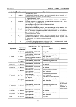
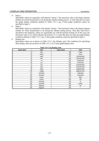


![B-64485EN/01 1.DISPLAY AND OPERATION
Limitation
- Data update cycle
Position-related data is updated at intervals of 1 ms, and power-related data is updated at the current cycle.
Therefore, even if you specify a sampling cycle that is shorter than the data update cycle, the displayed
data remains unchanged during the present data update cycle.
- Sampling cycle and the number of channels measured
Regarding the sampling cycle and the number of channels measured, there are limitations as shown in
Table 1.9.1.1 (k).
Table 1.9.1.1 (k) Sampling cycle and the number of channels measured
Sampling cycle Maximum number of channels measured
1ms or more 4
500μs 4
250μs 4
125μs 4
2
62.5μs
(Channel 3 or later cannot be input.)
The following limitations are imposed on the servo axis and spindle axis.
Number of channels that can be acquired per servo DSP
• Up to four channels can be acquired when the sampling cycle is 1 ms or longer, 500 μs, or 250 μs.
• Up to two channels can be acquired when the sampling cycle is 125 μs.
• Only one channel can be acquired when the sampling cycle is 62.25 μs.
Number of channels that can be acquired per spindle axis
• Up to two channels can be acquired when the sampling cycle is1 ms or longer.
• Only one channel can be acquired when the sampling cycle is 500 ms.
1.9.1.2 XY graph
This graph provides a 2-dimensional path display of measurement data by using 2-axis data.
Up to two draws can be displayed at a time.
Displaying and setting the XY graph
Procedure
The procedure for displaying the measurement data is described below.
1 Press the function key.
2 Press the continuous menu key several times until [SERVO GUIDE MATE] is displayed.
3 Click the soft key [SERVO GUIDE MATE].
4 Click the soft key [XY].
The wave display screen is displayed as shown Fig. 1.9.1.2 (a).
- 95 -](https://image.slidesharecdn.com/b-64485en01-121129013453-phpapp02/85/B-64485-en-01-117-320.jpg)
![1.DISPLAY AND OPERATION B-64485EN/01
Fig. 1.9.1.2 (a)
5 Click the soft key [MEASUREMENT].
6 Click the soft key [DATA IN].
7 Click the soft key [SAMPLING].
The data-in screen is displayed as shown Fig. 1.9.1.2 (b).
Fig. 1.9.1.2 (b)
8 Move the cursor to the parameter you want to set, by pressing the cursor key.
9 Enter data and the press the key.
10 Repeat steps 8 and 9 until you set all the parameters.
11 Click the soft key [SET CHANNEL].
The channel setting screen is displayed as shown Fig. 1.9.1.2 (c).
To set any channel other than the one currently displayed, display the setting screen for the desired
channel by pressing the or key.
- 96 -](https://image.slidesharecdn.com/b-64485en01-121129013453-phpapp02/85/B-64485-en-01-118-320.jpg)
![B-64485EN/01 1.DISPLAY AND OPERATION
Fig. 1.9.1.2 (c)
12 Move the cursor to the parameter you want to set, by pressing the cursor key.
13 Enter data and the press the key.
14 Repeat steps 12 and 13 until you set all the parameters.
15 Click the soft key [RE-DSPGRAPH].
16 Click the soft key [OPERATION & GRAPH].
The operation and graph setting screen is displayed as shown Fig. 1.9.1.2 (d).
To set any draw other than the one currently displayed, display the setting screen for the desired
draw by pressing the or key.
Fig. 1.9.1.2 (d)
17 Move the cursor to the parameter you want to set, by pressing the cursor key.
18 Enter data and the press the key.
19 Repeat steps 17 and 18 until you set all the parameters.
20 Click the soft key [RE-DSPGRAPH].
- 97 -](https://image.slidesharecdn.com/b-64485en01-121129013453-phpapp02/85/B-64485-en-01-119-320.jpg)
![1.DISPLAY AND OPERATION B-64485EN/01
21 Click the soft key [SCALE SET].
The scale setting screen is displayed as shown Fig. 1.9.1.2 (e).
Fig. 1.9.1.2 (e)
22 Move the cursor to the parameter you want to set, by pressing the cursor key.
23 Enter data and the press the key.
24 Repeat steps 22 and 23 until you set all the parameters.
25 Click the soft key [RE-DSPGRAPH].
26 Click the soft key [MEASUREMENT].
27 Click the soft key [START].
28 Start the automatic or manual operation.
29 When the measurement is completed, the wave display screen is displayed as shown Fig. 1.9.1.2 (f).
Fig. 1.9.1.2 (f)
- Changing the operation and graph setting screen
The procedure for changing the operation and graph setting screen as necessary is described below.
- 98 -](https://image.slidesharecdn.com/b-64485en01-121129013453-phpapp02/85/B-64485-en-01-120-320.jpg)
![B-64485EN/01 1.DISPLAY AND OPERATION
1 Click the soft key [OPERATION & GRAPH].
The operation and graph setting screen is displayed as shown Fig. 1.9.1.2 (g).
To set any draw other than the one currently displayed, display the setting screen for the desired
draw by pressing the or key.
Fig. 1.9.1.2 (g)
2 Move the cursor to the parameter you want to set, by pressing the cursor key.
3 Enter data and the press the key.
4 Repeat steps 2 and 3 until you set all the parameters.
5 Click the soft key [RE-DSPGRAPH].
Based on the new operation and graph settings, the wave display screen is displayed as shown Fig.
1.9.1.2 (h).
Fig. 1.9.1.2 (h)
- Changing the scale screen
The procedure for changing the scale settings as necessary is described below.
- 99 -](https://image.slidesharecdn.com/b-64485en01-121129013453-phpapp02/85/B-64485-en-01-121-320.jpg)
![1.DISPLAY AND OPERATION B-64485EN/01
1 Click the soft key [SCALE SET].
The scale setting screen is displayed as shown Fig. 1.9.1.2 (i).
Fig. 1.9.1.2 (i)
2 Move the cursor to the parameter you want to set, by pressing the cursor key.
3 Enter data and the press the key.
4 Repeat steps 2 and 3 until you set all the parameters.
5 Click the soft key [RE-DSPGRAPH].
Based on the new scale settings, the wave display screen is displayed as shown Fig. 1.9.1.2 (j).
Fig. 1.9.1.2 (j)
- Manipulating the XY graph
By clicking the following soft keys, you can perform the operations corresponding to them.
[MEASUREMENT] : Performs a measurement-related operation.
[←] : Shifts the horizontal axis to the right.
[→] : Shifts the horizontal axis to the left.
[H-AXIS EXP] : Expands the horizontal axis.
- 100 -](https://image.slidesharecdn.com/b-64485en01-121129013453-phpapp02/85/B-64485-en-01-122-320.jpg)
![B-64485EN/01 1.DISPLAY AND OPERATION
[H-AXIS RED] : Reduces the horizontal axis.
[AUTO SCALE] : Enables auto scaling.
[↑] : Shifts the vertical axis downward.
[↓] : Shifts the vertical axis upward.
[V-AXIS EXP] : Expands the vertical axis.
[V-AXIS RED] : Reduces the vertical axis.
[DRAW 1UNDSP] : Sets whether or not to display Draw 1.
[DRAW 2UNDSP] : Sets whether or not to display Draw 2.
[OPE/G SET] : Sets operations and graphs.
[SCALE SET] : Sets scales.
[COM1 INPUT] : Inputs comment 1.
[COM2 INPUT] : Inputs comment 2.
[Y-TIME] : Switches to the Y-Time graph.
[CIRCLE] : Switches to the Circle graph.
[FOURIER] : Switches to the Fourier graph.
[BODE] : Switches to the Bode graph.
- Performing measurement
When you click the soft key [MEASUREMENT], you can perform the operations corresponding to the
menu items that follow.
[START] : Starts measurement.
[ORIGIN] : Sets the origin value.
[STOP] : Stops measurement.
[DATA IN] : Specifies measurement-related settings.
- Changing measurement settings
1 When you click the soft key [MEASUREMENT] and then the soft key [DATA IN], you can perform
the operations corresponding to the menu items that follow.
2 Click the soft key [LIST].
The list screen is displayed as shown Fig. 1.9.1.2 (k).
To display any channel other than the one currently displayed, display the list screen for the desired
channel by pressing the or key.
Fig. 1.9.1.2 (k)
3 Check the current settings on the list screen.
- 101 -](https://image.slidesharecdn.com/b-64485en01-121129013453-phpapp02/85/B-64485-en-01-123-320.jpg)
![1.DISPLAY AND OPERATION B-64485EN/01
4 Click the soft key [SAMPLING].
The data-in screen is displayed as shown Fig. 1.9.1.2 (l).
Fig. 1.9.1.2 (l)
5 Move the cursor to the parameter you want to set, by pressing the cursor key.
6 Enter data and the press the key.
7 Repeat steps 5 and 6 until you set all the parameters.
8 Click the soft key [SET CHANNEL].
The channel setting screen is displayed as shown Fig. 1.9.1.2 (m).
To set any channel other than the one currently displayed, display the setting screen for the desired
channel by pressing the or key.
Fig. 1.9.1.2 (m)
9 Move the cursor to the parameter you want to set, by pressing the cursor key.
10 Enter data and the press the key.
11 Repeat steps 9 and 10 until you set all the parameters.
- 102 -](https://image.slidesharecdn.com/b-64485en01-121129013453-phpapp02/85/B-64485-en-01-124-320.jpg)
![B-64485EN/01 1.DISPLAY AND OPERATION
12 Click the soft key [RE-DSPGRAPH].
The wave display screen is displayed as shown Fig. 1.9.1.2 (n).
Fig. 1.9.1.2 (n)
13 The new settings will take effect next time you perform measurement. Change the operation/graph
settings and scale settings according to the new channel settings.
Explanation
- Setting the data-in screen
See the Explanation section for the Y-time graph describing the setting of the data-in screen.
- Setting the channel setting screen
See the Explanation section for the Y-time describing the setting of the channel setting screen.
- Setting the operation and graph setting screen
In the operation and graph setting screen, up to two graphs can be set per draw.
• Operation
The specifiable values are as shown in Table 1.9.1.2 (a), XY graph operations.
An operation cannot be specified if it does not meet the graph display conditions defined in Table
1.9.1.2 (b), XY graph conditions.
Table 1.9.1.2 (a) XY graph operations
Input value Operation name Description
1 N/A Not displayed.
XY display
11 XY
Input 1 is the horizontal axis. Input 2 is the vertical axis.
- 103 -](https://image.slidesharecdn.com/b-64485en01-121129013453-phpapp02/85/B-64485-en-01-125-320.jpg)

![B-64485EN/01 1.DISPLAY AND OPERATION
Limitation
See the Limitation section for the Y-time graph.
1.9.1.3 Circle graph
This graph displays an enlarged view of the path deviation from the specified circle arising during
circular cutting.
Only one draw can be displayed.
Displaying and setting the circle graph
Procedure
The procedure for displaying the measurement data is described below.
1 Press the function key.
2 Press the continuous menu key several times until [SERVO GUIDE MATE] is displayed.
3 Click the soft key [SERVO GUIDE MATE].
4 Click the soft key [CIRCLE].
The wave display screen is displayed as shown Fig. 1.9.1.3 (a).
Fig. 1.9.1.3 (a)
5 Click the soft key [MEASUREMENT].
6 Click the soft key [DATA IN].
- 105 -](https://image.slidesharecdn.com/b-64485en01-121129013453-phpapp02/85/B-64485-en-01-127-320.jpg)
![1.DISPLAY AND OPERATION B-64485EN/01
7 Click the soft key [SAMPLING].
The data-in screen is displayed as shown Fig. 1.9.1.3 (b).
Fig. 1.9.1.3 (b)
8 Move the cursor to the parameter you want to set, by pressing the cursor key.
9 Enter data and the press the key.
10 Repeat steps 8 and 9 until you set all the parameters.
11 Click the soft key [SET CHANNEL].
The channel setting screen is displayed as shown Fig. 1.9.1.3 (c).
To set any channel other than the one currently displayed, display the setting screen for the desired
channel by pressing the or key.
Fig. 1.9.1.3 (c)
12 Move the cursor to the parameter you want to set, by pressing the cursor key.
13 Enter data and the press the key.
14 Repeat steps 12 and 13 until you set all the parameters.
- 106 -](https://image.slidesharecdn.com/b-64485en01-121129013453-phpapp02/85/B-64485-en-01-128-320.jpg)
![B-64485EN/01 1.DISPLAY AND OPERATION
15 Click the soft key [RE-DSPGRAPH].
16 Click the soft key [OPERATION & GRAPH].
The operation and graph setting screen is displayed as shown Fig. 1.9.1.3 (d).
Fig. 1.9.1.3 (d)
17 Move the cursor to the parameter you want to set, by pressing the cursor key.
18 Enter data and the press the key.
19 Repeat steps 17 and 18 until you set all the parameters.
20 Click the soft key [RE-DSPGRAPH].
21 Click the soft key [SCALE SET].
The scale setting screen is displayed as shown Fig. 1.9.1.3 (e).
Fig. 1.9.1.3 (e)
22 Move the cursor to the parameter you want to set, by pressing the cursor key.
23 Enter data and the press the key.
24 Repeat steps 22 and 23 until you set all the parameters.
- 107 -](https://image.slidesharecdn.com/b-64485en01-121129013453-phpapp02/85/B-64485-en-01-129-320.jpg)
![1.DISPLAY AND OPERATION B-64485EN/01
25 Click the soft key [RE-DSPGRAPH].
26 Click the soft key [MEASUREMENT].
27 Click the soft key [START].
28 Start the automatic or manual operation.
29 When the measurement is completed, the wave display screen is displayed as shown Fig. 1.9.1.3 (f).
Fig. 1.9.1.3 (f)
- Changing the operation and graph setting screen
The procedure for changing the operation and graph setting screen as necessary is described below.
1 Click the soft key [OPERATION & GRAPH].
The operation and graph setting screen is displayed as shown Fig. 1.9.1.3 (g).
Fig. 1.9.1.3 (g)
2 Move the cursor to the parameter you want to set, by pressing the cursor key.
3 Enter data and the press the key.
4 Repeat steps 2 and 3 until you set all the parameters.
- 108 -](https://image.slidesharecdn.com/b-64485en01-121129013453-phpapp02/85/B-64485-en-01-130-320.jpg)
![B-64485EN/01 1.DISPLAY AND OPERATION
5 Click the soft key [RE-DSPGRAPH].
Based on the new operation and graph settings, the wave display screen is displayed as shown Fig.
1.9.1.3 (h).
Fig. 1.9.1.3 (h)
- Changing the scale screen
The procedure for changing the scale settings as necessary is described below.
1 Click the soft key [SCALE SET].
The scale setting screen is displayed as shown Fig. 1.9.1.3 (i).
Fig. 1.9.1.3 (i)
2 Move the cursor to the parameter you want to set, by pressing the cursor key.
3 Enter data and the press the key.
4 Repeat steps 2 and 3 until you set all the parameters.
5 Click the soft key [RE-DSPGRAPH].
Based on the new scale settings, the wave display screen is displayed as shown Fig. 1.9.1.3 (j).
- 109 -](https://image.slidesharecdn.com/b-64485en01-121129013453-phpapp02/85/B-64485-en-01-131-320.jpg)
![1.DISPLAY AND OPERATION B-64485EN/01
Fig. 1.9.1.3 (j)
- Manipulating the Circle graph
By clicking the following soft keys, you can perform the operations corresponding to them.
[MEASUREMENT] : Performs a measurement-related operation.
[←] : Moves the center coordinate position to the left.
[→] : Moves the center coordinate position to the right.
[↑] : Moves the center coordinate position upward.
[↓] : Moves the center coordinate position downward.
[AUTO SCALE] : Enables auto scaling.
[ERROR EXP] : Expands the error display.
[ERROR RED] : Reduces the error display.
[RADIUSEXP] : Expands the radius.
[RADIUSRED : Reduces the radius.
[DRAW 1UNDSP] : Sets whether or not to display Draw 1.
[ZOOM EXP] : Expands the zoom.
[ZOOM RED] : Reduces the zoom.
[OPE/G SET] : Sets operations and graphs.
[SCALE SET] : Sets scales.
[COM1 INPUT] : Inputs comment 1.
[COM2 INPUT] : Inputs comment 2.
[Y-TIME] : Switches to the Y-time graph.
[XY] : Switches to the XY graph.
[FOURIER] : Switches to the Fourier graph.
[BODE] : Switches to the Bode graph.
- Performing measurement
When you click the soft key [MEASUREMENT], you can perform the operations corresponding to the
menu items that follow.
[START] : Starts measurement.
[ORIGIN] : Sets the origin value.
[STOP] : Stops measurement.
[DATA IN] : Specifies measurement-related settings.
- 110 -](https://image.slidesharecdn.com/b-64485en01-121129013453-phpapp02/85/B-64485-en-01-132-320.jpg)
![B-64485EN/01 1.DISPLAY AND OPERATION
- Changing measurement settings
1 When you click the soft key [MEASUREMENT] and then the soft key [DATA IN], you can perform
the operations corresponding to the menu items that follow.
2 Click the soft key [LIST].
The list screen is displayed as shown Fig. 1.9.1.3 (k).
To display any channel other than the one currently displayed, display the list screen for the desired
channel by pressing the or key.
Fig. 1.9.1.3 (k)
3 Check the current settings on the list screen.
4 Click the soft key [SAMPLING].
The data-in screen is displayed as shown Fig. 1.9.1.3 (l).
Fig. 1.9.1.3 (l)
5 Move the cursor to the parameter you want to set, by pressing the cursor key.
6 Enter data and the press the key.
- 111 -](https://image.slidesharecdn.com/b-64485en01-121129013453-phpapp02/85/B-64485-en-01-133-320.jpg)
![1.DISPLAY AND OPERATION B-64485EN/01
7 Repeat steps 5 and 6 until you set all the parameters.
8 Click the soft key [SET CHANNEL].
The channel setting screen is displayed as shown Fig. 1.9.1.3 (m).
To set any channel other than the one currently displayed, display the setting screen for the desired
channel by pressing the or key.
Fig. 1.9.1.3 (m)
9 Move the cursor to the parameter you want to set, by pressing the cursor key.
10 Enter data and the press the key.
11 Repeat steps 9 and 10 until you set all the parameters.
12 Click the soft key [RE-DSPGRAPH].
The wave display screen is displayed as shown Fig. 1.9.1.3 (n).
Fig. 1.9.1.3 (n)
13 The new settings will take effect next time you perform measurement. Change the operation/graph
settings and scale settings according to the new channel settings.
- 112 -](https://image.slidesharecdn.com/b-64485en01-121129013453-phpapp02/85/B-64485-en-01-134-320.jpg)
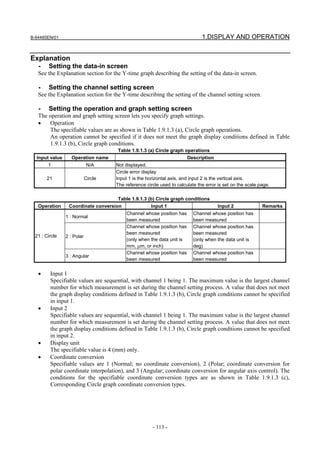
![1.DISPLAY AND OPERATION B-64485EN/01
Table 1.9.1.3 (c) Corresponding Circle graph coordinate conversion types
Specifiable coordinate
Operation Input 1 Input 2
conversion
Channel whose position has
Channel whose position has been measured 1 : Normal
been measured
Channel whose position has
Channel whose position has been measured
21 : Circle been measured 2 : Polar
(only when the data unit is mm, μm, or inch)
(only when the data unit is deg)
Channel whose position has
Channel whose position has been measured 3 : Angular
been measured
• Inclination
Specify the inclination in degrees. The specified value is effective only when Angular (coordinate
conversion for angular axis control) is specified as the coordinate conversion type.
- Setting the scale screen
• Center
Set the center coordinates of the circle (respective coordinates of the horizontal and vertical axes).
• Radius
Set the radius of the circle.
• Division
Set the scale of the circle display.
• Zoom
Set the zoom percentage when expanding the display in the direction of the center angle at the
quadrant change point (direction change point for each axis). This is effective for getting a detailed
view of quadrant protrusions. Under normal circumstances, set this value to 1.0.
- Performing measurement
See the Explanation section for the Y-time graph describing the performing measurement.
Limitation
See the Limitation section for the Y-time graph.
1.9.1.4 Fourier graph
This graph displays the frequency spectrum by performing digital Fourier conversion for the range of data
displayed by the Y-time graph.
Up to four draws can be displayed at a time.
Displaying and setting the Fourier graph
Procedure
The procedure for displaying the measurement data is described below.
1 Display the Y-time graph according to the relevant procedure.
2 Click the soft key [FOURIER].
The wave display screen is displayed as shown Fig. 1.9.1.4 (a).
- 114 -](https://image.slidesharecdn.com/b-64485en01-121129013453-phpapp02/85/B-64485-en-01-136-320.jpg)
![B-64485EN/01 1.DISPLAY AND OPERATION
Fig. 1.9.1.4 (a)
3 Click the soft key [OPERATION & GRAPH].
The operation and graph setting screen is displayed as shown Fig. 1.9.1.4 (b).
Fig. 1.9.1.4 (b)
4 Move the cursor to the parameter you want to set, by pressing the cursor key.
5 Enter data and the press the key.
6 Repeat steps 4 and 5 until you set all the parameters.
7 Click the soft key [RE-DSPGRAPH].
8 Click the soft key [SCALE SET].
The scale setting screen is displayed as shown Fig. 1.9.1.4 (c).
- 115 -](https://image.slidesharecdn.com/b-64485en01-121129013453-phpapp02/85/B-64485-en-01-137-320.jpg)
![1.DISPLAY AND OPERATION B-64485EN/01
Fig. 1.9.1.4 (c)
9 Move the cursor to the parameter you want to set, by pressing the cursor key.
10 Enter data and the press the key.
11 Repeat steps 9 and 10 until you set all the parameters.
12 Click the soft key [RE-DSPGRAPH].
The wave display screen is displayed as shown Fig. 1.9.1.4 (d).
Fig. 1.9.1.4 (d)
- Changing the operation and graph setting screen
The procedure for changing the operation and graph setting screen as necessary is described below.
1 Click the soft key [OPERATION & GRAPH].
The operation and graph setting screen is displayed as shown Fig. 1.9.1.4 (e).
- 116 -](https://image.slidesharecdn.com/b-64485en01-121129013453-phpapp02/85/B-64485-en-01-138-320.jpg)
![B-64485EN/01 1.DISPLAY AND OPERATION
Fig. 1.9.1.4 (e)
2 Move the cursor to the parameter you want to set, by pressing the cursor key.
3 Enter data and the press the key.
4 Repeat steps 2 and 3 until you set all the parameters.
5 Click the soft key [RE-DSPGRAPH].
Based on the new operation and graph settings, the wave display screen is displayed as shown Fig.
1.9.1.4 (f).
Fig. 1.9.1.4 (f)
- Changing the scale screen
The procedure for changing the scale settings as necessary is described below.
1 Click the soft key [SCALE SET].
The scale setting screen is displayed as shown Fig. 1.9.1.4 (g).
- 117 -](https://image.slidesharecdn.com/b-64485en01-121129013453-phpapp02/85/B-64485-en-01-139-320.jpg)
![1.DISPLAY AND OPERATION B-64485EN/01
Fig. 1.9.1.4 (g)
2 Move the cursor to the parameter you want to set, by pressing the cursor key.
3 Enter data and the press the key.
4 Repeat steps 2 and 3 until you set all the parameters.
5 Click the soft key [RE-DSPGRAPH].
Based on the new scale settings, the wave display screen is displayed as shown Fig. 1.9.1.4 (h).
Fig. 1.9.1.4 (h)
- Manipulating the Fourier graph
By clicking the following soft keys, you can perform the operations corresponding to them.
[MEASUREMENT] : Performs a measurement-related operation.
[GAIN ↑] : Shifts the gain graph downward.
[GAIN ↓] : Shifts the gain graph upward.
[GAIN V-EXP] : Expands the gain graph.
[GAIN V-RED] : Reduces the gain graph.
[AUTO SCALE] : Enables auto scaling.
- 118 -](https://image.slidesharecdn.com/b-64485en01-121129013453-phpapp02/85/B-64485-en-01-140-320.jpg)
![B-64485EN/01 1.DISPLAY AND OPERATION
[PHASE ↑] : Shifts the phase graph downward.
[PHASE ↓] : Shifts the phase graph upward.
[PHASE V-EXP] : Expands the phase graph.
[PHASE V-RED] : Reduces the phase graph.
[DRAW 1UNDSP] : Sets whether or not to display Draw 1.
[DRAW 2UNDSP] : Sets whether or not to display Draw 2.
[DRAW 3UNDSP] : Sets whether or not to display Draw 3.
[DRAW 4UNDSP] : Sets whether or not to display Draw 4.
[OPE/G SET] : Sets operations and graphs.
[SCALE SET] : Sets scales.
[COM1 INPUT] : Inputs comment 1.
[COM2 INPUT] : Inputs comment 2.
[Y-TIME] : Switches to the Y-Time.
[XY] : Switches to the XY graph.
[CIRCLE] : Switches to the Circle graph.
[BODE] : Switches to the Bode graph.
Explanation
- Setting the operation and graph setting screen
The operation and graph setting screen lets you specify up to four graph settings per draw.
• Operation
The specifiable values are as shown in Table 1.9.1.4 (a), Fourier graph operations.
An operation cannot be specified if it does not meet the graph display conditions defined in Table
1.9.1.4 (b), Fourier graph conditions.
Table 1.9.1.4 (a) Fourier graph operations
Input value Operation name Description
1 N/A Not displayed.
31 Fourier Displays the frequency spectrum by performing digital Fourier conversion.
Table 1.9.1.4 (b) Fourier graph conditions
Operation Condition Remarks
Draws of the Y-time graph correspond to those of the Fourier graph on
31 : Fourier a one-to-one basis. The Fourier operation can be set only when the
corresponding Y-time graph draw is effective.
- Setting the scale screen
• Start point
Set gain and phase data values for the center of the graph.
• Division
Set the value of one grid.
• Frequency
Set the minimum and maximum values of the horizontal axis. Since the unit is dependent on the time
range selected for the Y-time graph, 1 is not necessarily equal to 1 Hz.
(Example) When a 0.1-second time range is selected, 1 is equal to 1 Hz.
Limitation
See the Limitation section for the Y-time graph.
- 119 -](https://image.slidesharecdn.com/b-64485en01-121129013453-phpapp02/85/B-64485-en-01-141-320.jpg)
![1.DISPLAY AND OPERATION B-64485EN/01
1.9.1.5 Bode graph
This graph displays a Bode diagram for the measurement data in the form of a horizontal axis logarithm
graph.
Only one draw can be displayed at a time.
Displaying and setting the Bode graph
Procedure
To display the Bode graph, set the parameters for automatic vibration (disturbance input function) using
servo software.
The procedure for displaying the measurement data is described below.
1 Press the function key.
2 Press and hold this key until [PARAMETER] appears.
3 Set the following parameters.
No.2326 (Disturbance input gain) Recommended value: 500
No.2327 (Start frequency of disturbance input) Recommended value: 10
No.2328 (End frequency of disturbance input) Recommended value: 1000
No.2329 (Number of disturbance input measurement points) Recommended value:3
4 When bit 7 (DSTIN) of parameter No. 2270 changes from 0 to 1, disturbance input starts. This
operation needs to be performed to start measurement, so a program that changes bit 7 (DSTIN) of
parameter No. 2270 from 0 to 1 with program data input (G10) must have been created in advance.
Programming example: When the Z-axis (third axis) is vibrated (when bit 4 (G1B) of parameter 3454 is
1)
O1234
N1G10L52 ; Parameter input mode (this N number is used for a trigger.)
N2270 P3 Q7 R1; Set DSTIN (bit 7 of parameter No. 2270).
G11 ; Cancel the parameter input mode.
N2G04X10.; Wait for completion of vibration.
N99G10L52 ; Parameter input mode
N2270 P3 Q7 R0; Clear DSTIN (bit 7 of parameter No. 2270).
G11 ; Cancel the parameter input mode.
M30
5 Press the continuous menu key several times until [SERVO GUIDE MATE] is displayed.
6 Click the soft key [SERVO GUIDE MATE].
7 Click the soft key [BODE].
The wave display screen is displayed as shown Fig. 1.9.1.5 (a).
- 120 -](https://image.slidesharecdn.com/b-64485en01-121129013453-phpapp02/85/B-64485-en-01-142-320.jpg)
![B-64485EN/01 1.DISPLAY AND OPERATION
Fig. 1.9.1.5 (a)
8 Click the soft key [MEASUREMENT].
9 Click the soft key [DATA IN].
10 Click the soft key [SAMPLING].
The data-in screen is displayed as shown Fig. 1.9.1.5 (b).
Fig. 1.9.1.5 (b)
11 Move the cursor to the parameter you want to set, by pressing the cursor key.
12 Enter data and the press the key.
13 Repeat steps 11 and 12 until you set all the parameters.
14 Click the soft key [SET CHANNEL].
The channel setting screen is displayed as shown Fig. 1.9.1.5 (c).
To set any channel other than the one currently displayed, display the setting screen for the desired
channel by pressing the or key.
- 121 -](https://image.slidesharecdn.com/b-64485en01-121129013453-phpapp02/85/B-64485-en-01-143-320.jpg)
![1.DISPLAY AND OPERATION B-64485EN/01
Fig. 1.9.1.5 (c)
15 Move the cursor to the parameter you want to set, by pressing the cursor key.
16 Enter data and the press the key.
17 Repeat steps 15 and 16 until you set all the parameters.
To display the Bode graph, make the channel settings of the Bode graph in Table 1.9.1.5 (a). At this
time, be sure to disable channel 4 (axis for channel 4 is 0).
Table 1.9.1.5 (a) Bode graph channel settings
Channel 1 Channel 2 Channel 3
AXIS Specify the same servo motor axis.
TYPE 2 : TCMD 16 : FRTCM 15 : FREQ
UNIT 33 : % 33 : A(p) 32 : Hz
CONV.COEF 100 100 1
CONV.BASE 7282 -7282 1
ORIGIN VALUE 0 0 0
Set a trigger that corresponds to the program prepared in step 4.
(In the programming example, set N number for a trigger to 1.)
18 Click the soft key [RE-DSPGRAPH].
19 Click the soft key [OPERATION & GRAPH].
The operation and graph setting screen is displayed as shown Fig. 1.9.1.5 (d).
- 122 -](https://image.slidesharecdn.com/b-64485en01-121129013453-phpapp02/85/B-64485-en-01-144-320.jpg)
![B-64485EN/01 1.DISPLAY AND OPERATION
Fig. 1.9.1.5 (d)
20 Move the cursor to the parameter you want to set, by pressing the cursor key.
21 Enter data and the press the key.
22 Click the soft key [RE-DSPGRAPH].
23 Click the soft key [SCALE SET].
The scale setting screen is displayed as shown Fig. 1.9.1.5 (e).
Fig. 1.9.1.5 (e)
24 Move the cursor to the parameter you want to set, by pressing the cursor key.
25 Enter data and the press the key.
26 Repeat steps 21 and 22 until you set all the parameters.
27 Click the soft key [RE-DSPGRAPH].
28 Click the soft key [MEASUREMENT].
29 Click the soft key [START].
30 Perform automatic operation of the program prepared in step 4.
- 123 -](https://image.slidesharecdn.com/b-64485en01-121129013453-phpapp02/85/B-64485-en-01-145-320.jpg)
![1.DISPLAY AND OPERATION B-64485EN/01
28 When the measurement is completed, the wave display screen is displayed as shown Fig. 1.9.1.5 (f).
Fig. 1.9.1.5 (f)
- Changing the operation and graph setting screen
The procedure for changing the operation and graph setting screen as necessary is described below.
1 Click the soft key [OPERATION & GRAPH].
The operation and graph setting screen is displayed as shown Fig. 1.9.1.5 (g).
Fig. 1.9.1.5 (g)
2 Move the cursor to the parameter you want to set, by pressing the cursor key.
3 Enter data and the press the key.
4 Click the soft key [RE-DSPGRAPH].
Based on the new operation and graph settings, the wave display screen is displayed as shown Fig.
1.9.1.5 (h).
- 124 -](https://image.slidesharecdn.com/b-64485en01-121129013453-phpapp02/85/B-64485-en-01-146-320.jpg)
![B-64485EN/01 1.DISPLAY AND OPERATION
Fig. 1.9.1.5 (h)
- Changing the scale screen
The procedure for changing the scale settings as necessary is described below.
1 Click the soft key [SCALE SET].
The scale setting screen is displayed as shown Fig. 1.9.1.5 (i).
Fig. 1.9.1.5 (i)
2 Move the cursor to the parameter you want to set, by pressing the cursor key.
3 Enter data and the press the key.
4 Repeat steps 2 and 3 until you set all the parameters.
5 Click the soft key [RE-DSPGRAPH].
Based on the new scale settings, the wave display screen is displayed as shown Fig. 1.9.1.5 (j).
- 125 -](https://image.slidesharecdn.com/b-64485en01-121129013453-phpapp02/85/B-64485-en-01-147-320.jpg)
![1.DISPLAY AND OPERATION B-64485EN/01
Fig. 1.9.1.5 (j)
- Manipulating the Bode graph
By clicking the following soft keys, you can perform the operations corresponding to them.
[MEASUREMENT] : Performs a measurement-related operation.
[GAIN ↑] : Shifts the gain graph downward.
[GAIN ↓] : Shifts the gain graph upward.
[GAIN V-EXP] : Expands the gain graph.
[GAIN V-RED] : Reduces the gain graph.
[AUTO SCALE] : Enables auto scaling.
[PHASE ↑] : Shifts the phase graph downward.
[PHASE ↓] : Shifts the phase graph upward.
[PHASE V-EXP] : Expands the phase graph.
[PHASE V-RED] : Reduces the phase graph.
[DRAW 1UNDSP] : Sets whether or not to display Draw 1.
[OPE/G SET] : Sets operations and graphs.
[SCALE SET] : Sets scales.
[COM1 INPUT] : Inputs comment 1.
[COM2 INPUT] : Inputs comment 2.
[Y-TIME] : Switches to the Y-Time.
[XY] : Switches to the XY graph.
[CIRCLE] : Switches to the Circle graph.
[FOURIER] : Switches to the Fourier graph.
- Performing measurement
When you click the soft key [MEASUREMENT], you can perform the operations corresponding to the
menu items that follow.
[START] : Starts measurement.
[ORIGIN] : Sets the origin value.
[STOP] : Stops measurement.
[DATA IN] : Specifies measurement-related settings.
- Changing measurement settings
1 When you click the soft key [MEASUREMENT] and then the soft key [DATA IN], you can perform
the operations corresponding to the menu items that follow.
- 126 -](https://image.slidesharecdn.com/b-64485en01-121129013453-phpapp02/85/B-64485-en-01-148-320.jpg)
![B-64485EN/01 1.DISPLAY AND OPERATION
2 Click the soft key [LIST].
The list screen is displayed as shown Fig. 1.9.1.5 (k).
To display any channel other than the one currently displayed, display the list screen for the desired
channel by pressing the or key.
Fig. 1.9.1.5 (k)
3 Check the current settings on the list screen.
4 Click the soft key [SAMPLING].
The data-in screen is displayed as shown Fig. 1.9.1.5 (l).
Fig. 1.9.1.5 (l)
5 Move the cursor to the parameter you want to set, by pressing the cursor key.
6 Enter data and the press the key.
7 Repeat steps 5 and 6 until you set all the parameters.
- 127 -](https://image.slidesharecdn.com/b-64485en01-121129013453-phpapp02/85/B-64485-en-01-149-320.jpg)
![1.DISPLAY AND OPERATION B-64485EN/01
8 Click the soft key [SET CHANNEL].
The channel setting screen is displayed as shown Fig. 1.9.1.5 (m).
To set any channel other than the one currently displayed, display the setting screen for the desired
channel by pressing the or key.
Fig. 1.9.1.5 (m)
9 Move the cursor to the parameter you want to set, by pressing the cursor key.
10 Enter data and the press the key.
11 Repeat steps 9 and 10 until you set all the parameters.
12 Click the soft key [RE-DSPGRAPH].
The wave display screen is displayed as shown Fig. 1.9.1.5 (n).
Fig. 1.9.1.5 (n)
13 The new settings will take effect next time you perform measurement. Change the operation/graph
settings and scale settings according to the new channel settings.
- 128 -](https://image.slidesharecdn.com/b-64485en01-121129013453-phpapp02/85/B-64485-en-01-150-320.jpg)
![B-64485EN/01 1.DISPLAY AND OPERATION
Explanation
- Setting the data-in screen
See the Explanation section for the Y-time graph describing the setting the data-in screen.
- Setting the channel setting screen
See the Explanation section for the Y-time graph describing the setting the channel setting screen.
- Setting the operation and graph setting screen
The operation and graph setting screen lets you specify graph settings.
• Operation
The specifiable values are as shown in Table 1.9.1.5 (b), Bode graph operations.
An operation cannot be specified if it does not meet the graph display conditions defined in Table
1.9.1 (c), Bode graph conditions.
Table 1.9.1.5 (b) Bode graph operations
Input value Operation name Description
1 N/A Not displayed.
41 Bode Displays a Bode diagram in the form of a horizontal axis logarithm graph.
Table 1.9.1 (c) Bode graph conditions
Operation Condition
The measurement and channel settings must meet the following conditions.
CHANNEL 1 CHANNEL 2 CHANNEL 3
AXIS Specify the same servo motor axis.
TYPE 2 : TCMD 16 : FRTCM 15 : FREQ
41 : Bode UNIT 33 : % 33 : % 32 : Hz
CONV.COEF 100 100 1
CONV.BASE 7282 -7282 1
ORIGIN VALUE 0 0 0
Channel 4 must be disabled (channel 4 axis must be set to0).
- Setting the scale screen
• Start point
Set gain and phase data values for the center of the graph.
• Division
Set the value of one grid.
• Frequency
Set the minimum and maximum values of the horizontal axis. The unit is Hz.
- Performing measurement
See the Explanation section for the Y-time graph describing the performing measurement.
Limitation
See the Limitation section for the Y-time graph.
1.9.1.6 Parameters
#7 #6 #5 #4 #3 #2 #1 #0
2270 DSTIN DSTTAN DSTWAV DSTMV ACREF
[Input type] Parameter input
[Data type] Bit axis
- 129 -](https://image.slidesharecdn.com/b-64485en01-121129013453-phpapp02/85/B-64485-en-01-151-320.jpg)
![1.DISPLAY AND OPERATION B-64485EN/01
#3 ACREF Adaptive resonance elimination filter
0: Disabled
1: Enabled
When this function is enabled, disable it temporarily and then use the disturbance input
function.
(This is because the resonance elimination filter changes in response to the vibration of
the axis even if the vibration is caused by the disturbance input function.)
#4 DSTMV Usually, set 0.
#5 DSTWAV The input waveform of disturbance input is:
0: Sine wave.
1: Square wave.
Usually, set 0.
#6 DSTTN Disturbance is:
0: Input for one axis only.
1: Input for both the L and M axes.
Usually, set 0. To be set only for the L axis side of synchronous axes or tandem axes.
#7 DSTIN Disturbance input
0: Stop
1: Start
Disturbance input starts on the rising edge from 0 to 1.
2326 Disturbance input gain
[Input type] Parameter input
[Data type] Word axis
[Unit of data] TCMD unit (maximum amplifier current: 7282)
[Valid data range] 0 to 7282
First, set about 500 to apply vibration to the machine so that light sound is generated.
2327 Start frequency of disturbance input
[Input type] Parameter input
[Data type] Word axis
[Unit of data] Hz
[Valid data range] 1 to 2000
[Guide setting] 10
Set the frequency at which vibration starts.
2328 End frequency of disturbance input
[Input type] Parameter input
[Data type] Word axis
[Unit of data] Hz
[Valid data range] 1 to 2000
[Guide setting] 1000
Set the frequency at which vibration terminates.
2329 Number of disturbance input measurement points
[Input type] Parameter input
[Data type] Word axis
- 130 -](https://image.slidesharecdn.com/b-64485en01-121129013453-phpapp02/85/B-64485-en-01-152-320.jpg)
![B-64485EN/01 1.DISPLAY AND OPERATION
[Guide setting] 3
Set the number of measurement points by the disturbance input function (number of
vibrations).
For details on the disturbance input function, refer to the PARAMETER MANUAL
(B-65270EN) for the servo motor.
#7 #6 #5 #4 #3 #2 #1 #0
3454 G1B
[Input type] Parameter input
[Data type] Bit path
#4 G1B In programmable parameter input, the change command for a particular bit parameter is:
0: Disabled.
1: Enabled. (The bit number is specified by Q_.)
1.10 MAINTENANCE INFORMATION SCREEN
The maintenance information screen is provided to record the history of maintenance performed by a
service person of FANUC or machine tool builder.
The screen has the following features:
• MDI alphabetical input is allowed.
(Half-size kana input is for Japanese display only.)
• The recording screen can be scrolled in units of lines.
• Edited maintenance information can be input and output.
• Records are stored in Flash ROM.
• Double-byte (shift JIS) codes can be displayed.
1.10.1 Displaying the Maintenance Information Screen
1. Press function key .
2. Press continuous menu key several times until soft key [M-INFO] is displayed.
3. Press the soft key [M-INFO]. The maintenance information screen appears.
When selected, the maintenance screen shows the latest information.
The status (mode, number of empty character spaces, cursor line, column number) is displayed at the
bottom of the screen.
- 131 -](https://image.slidesharecdn.com/b-64485en01-121129013453-phpapp02/85/B-64485-en-01-153-320.jpg)
![1.DISPLAY AND OPERATION B-64485EN/01
Column
Line
<1> <2> <3> <4> <5> <6>
Fig. 1.10.1 (a) MAINTENANCE INFORMATION screen
Status display
<1> Kana/alphabetic
KN: Half-size kana input mode.
ABC: English input mode
<2> OVER / INSERT
OVER: Overwrite mode
INSERT: Insert input mode.
<3> EDIT / READ
EDIT: Editing allowed
READ: Editing inhibited
<4> Number of empty character spaces
Number of empty character spaces as half-size characters
<5> Current cursor line
Position of the line on which the cursor is currently located.
<6> Current cursor column
Position of the column at which the cursor is currently located.
NOTE
The numbers of lines and columns that can be displayed by each LCD are:
• 10.4” display unit: 37 characters × 12 lines
• 8.4” display unit: 38 characters × 11 lines
• 15” display unit: 38 characters × 19 lines
1.10.2 Operating the Maintenance Information Screen
The maintenance information screen has view mode and edit mode, which are selected by pressing the
soft key [END] or [EDIT].
Initially, view mode is selected. To start editing, select edit mode by pressing the soft keys [(OPRT)] and
[EDIT]. When the editing is completed, press the soft key [END] key. Then, select soft key [SAVE] or
[QUIT]. Unless soft key [SAVE] is selected, the edited data will be lost at next power-up.
- 132 -](https://image.slidesharecdn.com/b-64485en01-121129013453-phpapp02/85/B-64485-en-01-154-320.jpg)
![B-64485EN/01 1.DISPLAY AND OPERATION
To scroll the screen showing the recorded information, press a cursor keys or page keys on the MDI
panel.
The following keys are used for editing (character input) and viewing:
Table 1.10.2 (a) Table of (edit) operations on the maintenance information screen
Mode Key Description
View Soft key
[EDIT] Allows editing.
[JUMP] Displays the beginning or the end.
Cursor keys Scrolls the screen up or down.
Page keys Scrolls the screen up or down in units of whole screens.
Edit Soft key
[END] Ends editing. Select whether to save the edited data.
[KN/ABC] Switches between half-size kana input and alphabetic input modes.
(Supports Japanese display only.)
[CLEAR ALL] Clears all maintenance information. (This key is enabled when the bit 7
(MDC) of parameter No. 3116 is set to 1.)
[I/O] Reads or punches the maintenance information.
[JUMP] Moves the cursor to the beginning or end.
Cursor keys Moves the cursor position up or down.
Page keys Scrolls the screen up or down in units of whole screens.
Alphanumeric/ special Allows alphabetical, numeric, or special character input. (For details of
character keys half-size kana input, see Item, " Half-size kana input".)
key Switches between insert and overwrite modes.
• If the key input buffer does not contain any character, deletes the one
character at the cursor position.
key
• If the key input buffer contains characters, deletes the characters from the
buffer.
• If the key input buffer does not contain any character, deletes the one
character before the cursor.
key
• If the key input buffer contains characters, deletes the one character from
the buffer.
• If the key input buffer does not contain any character, starts a new line.
key • If the key input buffer contains characters, outputs the characters from the
buffer to the information screen.
1.10.3 Half-Size Kana Input on the Maintenance Information Screen
By pressing soft key [KN/ABC], you can switch between half-size kana input and alphabetic input
modes.
In half-size kana input mode, alphabetic characters are converted in accordance with the "half-size
kana/Roman character conversion table" and resultant half-size kana characters are displayed in the key
input buffer.
Pressing the key causes the characters in the key input buffer to be output to maintenance
information.
Pressing the key causes the characters to be deleted from the key input buffer and the one
character of the maintenance information on which the cursor is positioned to be deleted.
Pressing the key causes cancels conversion, and deletes one character from the key input buffer. If
the key input buffer does not contain any character, the one character of the maintenance information that
immediately precedes the cursor is deleted.
- 133 -](https://image.slidesharecdn.com/b-64485en01-121129013453-phpapp02/85/B-64485-en-01-155-320.jpg)
![1.DISPLAY AND OPERATION B-64485EN/01
1.10.4 Warnings That Occurs on the Maintenance Information
Screen
The following warnings occur on the maintenance information screen.
Warning message Meaning
NO MORE SPACE An overflow occurred in CNC memory.
ALARM The operation could not be performed because an alarm was
generated in the CNC.
BUSY Wait for CNC processing to end or make a retry.
ILLEGAL DATA Investigate data and correct it as required.
WRONG MODE The CNC is in wrong mode.
COMMAND ILLEGAL USE A corresponding CNC option cannot be found.
PARAMETER ERROR CNC parameter settings contain an error.
EDIT REJECTED An attempt was made to perform an edit operation on data that could
not be edited.
WRITE PROTECT Writing is prohibited.
COMMAND REJECT The CNC rejected the execution of the processing. Check the
execution conditions.
1.10.5 Parameter
#7 #6 #5 #4 #3 #2 #1 #0
3116 MDC
[Input type] Setting input
[Data type] Bit path
#7 MDC Maintenance information data:
0: Cannot be erased entirely.
1: Can be erased entirely.
#7 #6 #5 #4 #3 #2 #1 #0
3206 MIF
[Input type] Parameter input
[Data type] Bit
#1 MIF Editing of the maintenance information screen is:
0: Not prohibited.
1: Prohibited.
#7 #6 #5 #4 #3 #2 #1 #0
8901 MEN
[Input type] Setting input
[Data type] Bit path
#7 MEN The periodic maintenance screen is:
0: Displayed.
1: Not displayed.
- 134 -](https://image.slidesharecdn.com/b-64485en01-121129013453-phpapp02/85/B-64485-en-01-156-320.jpg)
![B-64485EN/01 1.DISPLAY AND OPERATION
1.10.6 Overview of the History Function
It is possible to record history of operations performed by the operator, alarms that occurred, external
operator messages, etc. in order to check the history or output history data.
1 Conditions under which history is recorded
a Display screen
History is recorded when a screen other than the operation history screen is displayed.
b Signal selection
Up to 60 input/output signals for which history is recorded can be selected.
c Parameter setting
It is possible to set parameters in order to specify individually whether to record data change
history such as operation history of the MDI key, history of external operator messages,
addition of external alarms/messages, parameters/tool offset, workpiece offset (workpiece shift
amount)/custom macro common variable, operation history of input/output signals.
d Storage capacity
When the storage capacity is exhausted, data is deleted in the chronological order, oldest first.
A maximum of approximately 8000 history items can be recorded when, for example, only the
operation history of the MDI key is stored.
2 Data output
All the history data items stored can be output to an external input/output unit (see the section about
outputting of all history data).
3 Deletion of history
When bit 7 (EKE) of parameter No. 3195 is 1, soft key [ALL CLEAR] appears, which can be used
to delete history data.
#7 #6 #5 #4 #3 #2 #1 #0
3195 EKE
[Data type] Bit
#7 EKE The [ALL CLEAR] soft key for clearing all history data is:
0: Not displayed.
1: Displayed.
NOTE
1 History data is not cleared even after power-off.
If memory clear operation is performed, however, history data is also deleted.
2 The correct date and time need to be set on the setting screen.
3 All history data items including alarms, external operator messages, operations,
and input/output signals are integrated into one and stored in a single storage
area. Therefore, when the storage capacity is exhausted, data is deleted in the
chronological order, oldest first, regardless of the type of history.
The deletion of history data deletes all history data, so care should be executed
before performing deletion.
Delete operation cannot be performed on a per-history-type basis.
- 135 -](https://image.slidesharecdn.com/b-64485en01-121129013453-phpapp02/85/B-64485-en-01-157-320.jpg)
![1.DISPLAY AND OPERATION B-64485EN/01
1.10.6.1 Alarm history
Only alarm history is extracted from all history data recorded and displayed on the screen. When the
amount of history data exceeds the storage capacity, data is automatically deleted in the chronological
order, oldest first.
Fig. 1.10.6.1 (a) Alarm history screen
Screen display
The alarms that occurred are displayed in the chronological order, most recent first.
The following items are indicated for each alarm.
Path name (only for multi-path operation)
Date and time of alarm issuance
Alarm type and number
Alarm message
NOTE
To record external alarm and macro alarm messages as history data, set bit 3
(EAH) of parameter No. 3112 to 1 and bit 7 (HAL) of parameter No. 3196 to 0.
If the path name, axis name, or spindle name is changed after occurrence of an alarm, the new name is
displayed on the alarm history screen.
For modal 'O' data, only the first five characters are output in the case of the program name.
- Procedure
1 Press function key to display the screen for parameters etc.
2 Press return menu key .
3 Press the continuous menu key several times until soft key [HISTORY] is displayed.
4 Press soft key [HISTORY] to display the alarm history screen.
5 Press page switching keys to move between the previous page and the next page.
- 136 -](https://image.slidesharecdn.com/b-64485en01-121129013453-phpapp02/85/B-64485-en-01-158-320.jpg)
![B-64485EN/01 1.DISPLAY AND OPERATION
Deleting history data on the alarm history screen
- Procedure
1 Display the alarm history screen.
2 Press the soft key [(OPRT)].
3 If soft key [(CLEAR)] is pressed, all history data is deleted.
NOTE
The delete operation deletes not only alarm history, but also external operator
message history, operation history, and other history data. Delete operation
cannot be performed on a per-history-type basis.
Holding alarm history
Alarm history is held in the same storage area as in other history data such as key operation history and
signal change history. Therefore, alarm history is deleted when the storage capacity is fully exhausted by
other history data.
When bit 2 (SAH) of parameter No. 11354 is set to 1, alarm history data is stored in the area specific to
alarm history and recorded in the storage area for operation history. Accordingly, up to 50 alarm history
items can be held even if the storage capacity is fully exhausted by other history data.
However, additional information (modal data, absolute coordinates, and machine coordinates during
occurrence of an alarm) is not recorded in the area specific to alarm history. (The additional information
is recorded in the storage area of operation history.)
Deleting alarm history
If history is deleted on the alarm history screen when bit 2 (SAH) of parameter No. 11354 is set to 1, only
the alarm history is deleted. Even if history is deleted on the operation history screen or external operator
message screen, alarm history is not deleted.
Parameter setting
#7 #6 #5 #4 #3 #2 #1 #0
11354 SAH
[Data type] Bit
#2 SAH When the storage capacity for history data is exceeded due to non-alarm history, alarm
history will be:
0: Erased.
1: Erased, except the most recent 50 items of history data.
Displaying an external alarm or macro alarm
When an external alarm or macro alarm is caused by setting the following parameters, the message in
addition to the alarm number can be recorded in alarm history.
#7 #6 #5 #4 #3 #2 #1 #0
3112 EAH
[Data type] Bit
#3 EAH Messages of the external alarm/macro alarm in alarm or operation history:
0: Not recorded
1: Recorded
- 137 -](https://image.slidesharecdn.com/b-64485en01-121129013453-phpapp02/85/B-64485-en-01-159-320.jpg)
![1.DISPLAY AND OPERATION B-64485EN/01
NOTE
This parameter is valid when bit 7 (HAL) of parameter No. 3196 is
set to 0.
#7 #6 #5 #4 #3 #2 #1 #0
3196 HAL
[Input type] Parameter input
[Data type] Bit
#7 HAL When an alarm is issued, additional information (modal data, absolute coordinates, and
machine coordinates present at the issuance of the alarm) is:
0: Recorded in the operation history and alarm history.
1: Not recorded in the operation history and alarm history.
NOTE
1 Since alarms, operations, external operator messages, and data
change history are held in the same storage area, alarm history
may be deleted if the storage capacity is fully exhausted by other
history data.
2 The maximum number of history items that can be recorded is
shown below (when the history items are alarms).
When bit 7 (HAL) of parameter No. 3196 is 1, the maximum
number is approximately 4000.
When bit 7 (HAL) of parameter No. 3196 is 0, the maximum
number depends on the system because the modal information
and coordinates during occurrence of an alarm are also recorded.
(Example: 280 for 5-axis systems and 200 for 10-axis systems)
When bit 3 (EAH) of parameter No. 3112 is 1, however, messages
for macro alarms and external alarms are also recorded, the
maximum number is further reduced.
1.10.6.2 External operator message history
Only external operator message history and macro message history are extracted from all history data
recorded and displayed on the screen. When the amount of history data exceeds the storage capacity, data
is automatically deleted in the chronological order, oldest first.
- 138 -](https://image.slidesharecdn.com/b-64485en01-121129013453-phpapp02/85/B-64485-en-01-160-320.jpg)
![B-64485EN/01 1.DISPLAY AND OPERATION
Fig. 1.10.6.2 (a) External operator message history screen
Screen display
- Procedure
1 Press function key .
2 Press the continuous menu key several times until soft key [MESSAGE HISTRY]] is
displayed.
3 Press soft key [MESSAGE HISTRY]] to display the external operator message history screen.
4 Press page switching keys to move between the previous page and the next page.
NOTE
1 Since external operator messages, operations, alarms, and data change history
are held in the same storage area, external operator message history may be
deleted if the storage capacity is fully exhausted by other history data.
2 The maximum number of history items that can be recorded is approximately
150 (when the history items are external operator messages).
Deleting history data from the external operator message history screen
- Procedure
1 Display the external operator message history screen.
2 Press the soft key [(OPRT)].
3 If soft key [CLEAR] is pressed, all history data is deleted.
NOTE
The delete operation deletes not only external operator message history, but
also operation history, alarm history, and other history data. Delete operation
cannot be performed on a per-history-type basis.
Holding external operator message history
External operator message history is held in the same storage area as in other history data such as key
operation history and signal change history. Therefore, external operator message history is deleted when
the storage capacity is fully exhausted by other history data.
- 139 -](https://image.slidesharecdn.com/b-64485en01-121129013453-phpapp02/85/B-64485-en-01-161-320.jpg)
![1.DISPLAY AND OPERATION B-64485EN/01
When bit 3 (SOH) of parameter No. 11354 is set to 1, external operator message history data is stored in
the area specific to external operator message history and recorded in the storage area for operation
history. Accordingly, external operator message history items can be held even if the storage capacity is
fully exhausted by other history data.
Deleting external operator message history
If history is deleted on the external operator message history screen when bit 3 (SOH) of parameter No.
11354 is set to 1, only the external operator message history is deleted. Even if history is deleted on the
operation history screen or alarm history screen, external operator message history is not deleted.
Number of characters in external operator message history and number of
external operator messages
When bit 3 (SOH) of parameter No. 11354 is set to 1, the number of characters in external operator
message history and the number of external operator messages are set by bit 6 (MS0) and bit 7 (MS1) of
parameter No. 3113. The correspondence between the settings, the number of characters, and the number
of messages is shown in Table 1.10.6.2 (a).
Table 1.10.6.2 (a)
Parameter Maximum number of characters Number of messages
MS0=0 MS1=0 255 8
MS0=1 MS1=0 200 10
MS0=0 MS1=1 100 18
MS0=1 MS1=1 50 32
Parameter setting
#7 #6 #5 #4 #3 #2 #1 #0
3112 OMH
[Input type] Parameter input
[Data type] Bit
#2 OMH The external operator message history screen is:
0: Not displayed.
1: Displayed.
#7 #6 #5 #4 #3 #2 #1 #0
3113 MS1 MS0 HMC
[Input type] Parameter input
[Data type] Bit
#0 HMC The contents of the external operator message history:
0: Cannot be erased.
1: Can be erased.
NOTE
This parameter is valid when bit 3 (SOH) of parameter No. 11354 is
set to 1.
#6 MS0
#7 MS1 Set the combination of the number of characters and the number of messages to be
preserved in the external operator message history.
- 140 -](https://image.slidesharecdn.com/b-64485en01-121129013453-phpapp02/85/B-64485-en-01-162-320.jpg)
![B-64485EN/01 1.DISPLAY AND OPERATION
Table 1.10.6.2 (b)
Parameter Maximum number of characters Number of messages
MS0=0 MS1=0 255 8
MS0=1 MS1=0 200 10
MS0=0 MS1=1 100 18
MS0=1 MS1=1 50 32
NOTE
1 Although up to 255 characters can be specified for each external
operator message, you can use the combination of bits 6 (MS0)
and 7 (MS1) of parameter No. 3113 to limit the number of
characters and select the number of messages to be preserved in
the external operator message history.
2 The settings of bits 6 (MS0) and 7 (MS1) of parameter No. 3113
take effect the next time the power is turned on. The external
operator message history is erased at that time.
3 Even though you change the settings of bits 6 (MS0) and 7 (MS1)
of parameter No. 3113, the alarm PW0000, "POWER MUST BE
OFF" is not issued. You must however turn on the power again
before the new settings can take effect.
4 If text (such as single-byte katakana or kanji characters) is entered
in character code, the number of characters recorded in the
external operator message history may be smaller than the
maximum number of characters set by bits 6 (MS0) and 7 (MS1) of
parameter No. 3113.
#7 #6 #5 #4 #3 #2 #1 #0
3196 HOM
[Input type] Parameter input
[Data type] Bit
#6 HOM A history of external operator messages and macro messages ((#3006) is:
0: Recorded.
1: Not recorded.
#7 #6 #5 #4 #3 #2 #1 #0
11354 SOH
[Input type] Parameter input
[Data type] Bit
#3 SOH When the storage capacity for history data is exceeded due to data other than external
operator message history, external operator message history will be:
0: Erased.
1: Retained.
NOTE
1 The setting of bit 3 (SOH) of parameter No. 11354 will be effective
the next time the power is turned on. At this time, all history data
(operation history, alarm history, and external operator message
history) will be erased.
- 141 -](https://image.slidesharecdn.com/b-64485en01-121129013453-phpapp02/85/B-64485-en-01-163-320.jpg)

![B-64485EN/01 1.DISPLAY AND OPERATION
3122 Time interval used to record time data in operation history
[Input type] Parameter input
[Data type] Word
[Unit of data] min
[Valid data range] 0 to 1440
Time data is recorded in operation history at specified time intervals.
When 0 is set, the specification of a time period of 10 minutes is assumed.
If data to be recorded is not present within the time period, no time data is recorded.
NOTE
This parameter must be set to the same value for all paths.
#7 #6 #5 #4 #3 #2 #1 #0
3195 EKE HDE HKE
[Input type] Parameter input
[Data type] Bit
#5 HKE A key operation history is:
0: Recorded.
1: Not recorded.
#6 HDE A DI/DO history is:
0: Recorded.
1: Not recorded.
#7 EKE The [ALL CLEAR] soft key for clearing all history data is:
0: Not displayed.
1: Displayed.
#7 #6 #5 #4 #3 #2 #1 #0
3196 HAL HOM HMV HPM HWO HTO
[Input type] Parameter input
[Data type] Bit
#0 HTO A modification history of tool offset data is:
0: Not recorded.
1: Recorded.
#1 HWO A modification history of workpiece offset data/extended workpiece offset
data/workpiece shift (T series) is:
0: Not recorded.
1: Recorded.
#2 HPM A modification history of parameters is:
0: Not recorded.
1: Recorded.
#3 HMV A modification history of custom macro common variables is:
0: Not recorded.
1: Recorded.
- 143 -](https://image.slidesharecdn.com/b-64485en01-121129013453-phpapp02/85/B-64485-en-01-165-320.jpg)
![1.DISPLAY AND OPERATION B-64485EN/01
#6 HOM A history of external operator messages and macro messages ((#3006) is:
0: Recorded.
1: Not recorded.
#7 HAL When an alarm is issued, additional information (modal data, absolute coordinates, and
machine coordinates present at the issuance of the alarm) is:
0: Recorded in the operation history and alarm history.
1: Not recorded in the operation history and alarm history.
To record as many alarm history items as possible, rather than detailed alarm information,
set 1. In addition, 10 G code modal group numbers that need to be recorded are set in
parameters Nos. 12990 to 12999.
12990 G code modal group (first one) to be recorded as history data when an alarm is issued
to to
12999 G code modal group (tenth one) to be recorded as history data when an alarm is issued
[Input type] Parameter input
[Data type] Byte path
[Valid data range] 1 to maximum G code group number
Set a G code modal group number to be recorded as alarm history and operation history
data when an alarm is issued.
* If a specified value falls outside the data range, the states of groups 01 to 10 are
recorded.
Screen display
- Procedure
1 Press function key .
2 Press the continuous menu key several times until soft key [OPERAT HISTRY] is displayed.
3 Press soft key [OPERAT HISTRY] and then press soft key [OPERAT HISTRY] that newly appears
to display the operation history screen.
4 To display subsequent operation history, press page switching keys to move between the
previous page and the next page.
To display the portion between pages, press one of cursor keys to shift the display by
half page.
(For the 8.4-inch display unit, however, the display shifts by one column.)
When soft key [(OPRT)] is pressed on the operation history screen, the following soft key operations
can be performed.
a Pressing [TOP] displays the first page, which contains the oldest data.
b Pressing [BOTTOM] displays the last page, which contains the latest data.
c Pressing [NO.SRH] displays specified operation history data.
(Example) Entering 50 and pressing [NO.SRH] display 50th data.
- 144 -](https://image.slidesharecdn.com/b-64485en01-121129013453-phpapp02/85/B-64485-en-01-166-320.jpg)
![B-64485EN/01 1.DISPLAY AND OPERATION
Fig. 1.10.6.3 (a) Operation history screen
Displayed information
1 Serial number and display start history number/total number of history items
A serial number is indicated to the left of each of recorded history data items. The smaller the serial
number, the older the data item.
The display start history number/total number of history items is displayed at the upper right of the
screen. The number of history data items that is not displayed on the screen is not included in the
total number of history items.
2 Data
• MDI key
When bit 5 (HKE) of parameter No. 3195 is 0, key operations are recorded.
A key operation is preceded by a path number as follows: 1_[LEFT F] or 2_[LEFT F]. (When
the number of paths is 1, no path number is displayed.)
P_ of P_[LEFT F] indicates an external key operation.
i Address keys, numerical keys
Characters such as A to Z, 0 to 9, ";", "+", and "-" are directly displayed with black text.
ii Function menu keys, operation menu keys, soft keys
A key name is enclosed by square brackets as follows and displayed with green text:
[LEFT F], [SOFT 1] to [SOFT 10], [RIGHT F].
iii Function keys, page keys, cursor keys, etc.
A key name is enclosed by angle brackets as follows and displayed with green text:
<POS>, <SYSTEM>, <PAGE ↑>, <CUR →>, <RESET>, <INPUT>, etc.
iv Key at power-on
A key name is displayed with white text against a green background.
- 145 -](https://image.slidesharecdn.com/b-64485en01-121129013453-phpapp02/85/B-64485-en-01-167-320.jpg)

![B-64485EN/01 1.DISPLAY AND OPERATION
1 Detailed data during occurrence of an alarm
When bit 7 (HAL) of parameter No. 3196 is 0, 10 G code modals of the block that was being
executed during occurrence of an alarm, the second auxiliary function codes D, E, F, H, M, N, O, S,
and T, absolute values, and machine coordinates are recorded together with the alarm number and
the time of occurrence.
The group numbers of 10 G code modals to be recorded are set in parameters Nos. 12990 to 12999.
If they are not set, the G code modals of groups 01 to 10 are recorded.
NOTE
For modal 'O' data, only the first five characters are recorded in the case of the
program name.
To increase the number as compared with detailed data on occurrence of an
alarm, set bit 7 (HAL) of parameter No. 3196 to 1.
2 External alarm message and macro alarm message
When bit 3 (EAH) of parameter No. 3112 is 1, external alarm messages and macro alarm messages
can be recorded as history data. However, only the first 64 characters are recorded.
NOTE
To record external alarm messages and macro alarm messages as history data,
set bit 3 (EAH) of parameter No. 3112 to 1 and bit 7 (HAL) of parameter No.
3196 to 0.
3 Changing the tool offset data
When bit 0 (HTO) of parameter No. 3196 is 1, changing the tool offset data records the changed
offset number and type, the changed tool offset data, the new tool offset data, and the change time.
4 Changing the workpiece offset, extended workpiece offset, or workpiece shift (T series) data
When bit 1 (HWO) of parameter No. 3196 is 1, changing the workpiece offset data records the
changed offset number, the changed workpiece offset data, the new workpiece offset data, and the
change time. These items are also recorded when the extended workpiece offset or workpiece shift
amount (for the T series) is changed.
5 Changing a parameter
When bit 2 (HPM) of parameter No. 3196 is 1, changing a parameter records the changed parameter
number, type (axis type, spindle type, path type, and machine group type), the changed parameter
data, the new parameter data, and the change time.
NOTE
History concerning changes during power-on and changes of the password and
keys is not recorded.
6 Changing custom macro common variables (#100 to #999)
When bit 3 (HMV) of parameter No. 3196 is 1, changing a custom macro common variable records
the changed common variable number, the changed common variable value, the new common
variable value, and the change time.
Deleting history data on the operation history screen
- Procedure
1 Display the operation history screen.
2 Press the soft key [(OPRT)].
- 147 -](https://image.slidesharecdn.com/b-64485en01-121129013453-phpapp02/85/B-64485-en-01-169-320.jpg)
![1.DISPLAY AND OPERATION B-64485EN/01
3 Press the soft key [ALL CLEAR].
4 If soft key [EXEC] is pressed, all history data is deleted.
NOTE
The delete operation deletes not only operation history, but also external
operator message history, alarm history, and other history data. Delete operation
cannot be performed on a per-history-type basis.
1.10.6.4 Operation history signal selection
An input/output signal for recording history can be selected. A maximum of 60 signals can be set.
Setting data
1 Press function key .
2 Press the continuous menu key several times until soft key [OPERAT HISTRY] is displayed.
3 Press soft key [OPERAT HISTRY].
4 Press soft key [SIGNAL SELECT] to display the operation history signal selection screen.
5 Press soft key [(OPRT)].
6 Press cursor movement keys to move the cursor to a desired position.
7 Operate keys to enter the signal type (X, G, F, or Y) followed by the address and press .
Example) Entering G0004 and pressing :
Then entered signal address "G0004" appears in the ADDRES position and the initial value
"00000000" is set in the SIGNAL position.
8 Select the bit to be recorded as history.
To change all bits of a specified signal address, move the cursor so that all bits are displayed in
reverse video as "00000000" and then press soft key [ON:1] or [OFF:0] to change the bits to
"11111111" or "00000000".
To change only a particular bit, move the cursor with cursor movement keys to the bit to
be changed and then press soft key [ON:1] or [OFF:0] to change the bits to 1 or 0.
9 A maximum of 60 signals can be selected. It is not necessary to set signals contiguously from No. 1.
NOTE
1 When the operation history signal selection screen is displayed, no history is
recorded.
2 The addresses that can be set for an input/output signal are X, Y, G, and F only.
When no data is set, ******** appears.
3 If all bits are 0 even when an address is set, no history is recorded.
4 When the ON/OFF width of an input signal is 4 msec or less, nothing is recorded
in history data. Some signals are not recorded.
5 When the number of selected signals is large, the processing speed may be
reduced.
Clearing individual data items
1 Display the operation history signal selection screen.
2 Move the cursor to the data to be cleared.
3 Press soft key [DELETE].
4 Press soft key [EXEC].
- 148 -](https://image.slidesharecdn.com/b-64485en01-121129013453-phpapp02/85/B-64485-en-01-170-320.jpg)
![B-64485EN/01 1.DISPLAY AND OPERATION
Clearing all data items
1 Display the operation history signal selection screen.
2 Press soft key [ALLDEL].
3 Press soft key [EXEC].
Fig. 1.10.6.4 (a) Operation history signal selection screen
Selection by the parameter
When bit 4 (PHS) of parameter No. 3206 is 1, an input/output signal for which history is recorded can be
set by the parameter.
When a signal is selected or deselected on the operation history signal selection screen in this case, the
value of the corresponding parameter automatically changes. When the value of the parameter is changed
on the parameter screen, the display of the operation history signal selection screen changes.
This is the same as in input operations. When operation history signal selection data is input on the
operation history signal selection screen, the value of the corresponding parameter automatically changes.
When the value of parameter is input on the parameter screen, the display of the operation history signal
selection screen changes.
The first 20 data items of the 60 data items can be set by the parameter.
Parameter setting
#7 #6 #5 #4 #3 #2 #1 #0
3206 PHS
[Input type] Parameter input
[Data type] Bit
#4 PHS Operation history signal selection:
0: Does not interact with parameters.
Operation history signal selection is added or deleted on the operation history signal
selection screen.
Changing the settings of parameters Nos. 24901 to 24920, Nos. 12801 to 12820,
Nos. 12841 to 12860, or Nos. 12881 to 12900 has no effect on operation history
signal selection.
Changes to the signals of the addresses specified by parameters Nos. 24901 to 24920,
Nos. 12801 to 12820, Nos. 12841 to 12860, or Nos. 12881 to 12900 are not
recorded in the history.
- 149 -](https://image.slidesharecdn.com/b-64485en01-121129013453-phpapp02/85/B-64485-en-01-171-320.jpg)
![1.DISPLAY AND OPERATION B-64485EN/01
1: Interacts with parameters.
Operation history signal selection can be performed either on the operation history
signal selection screen or by setting parameters.
NOTE
Setting this parameter to 1 reflects the current operation history
signal selection data on parameters Nos. 24901 to 24920 and Nos.
12801 to 12900.
24901 Operation history signal selection PMC path number (No. 01)
to to
24920 Operation history signal selection PMC path number (No. 20)
[Input type] Parameter input
[Data type] Byte
[Valid data range] 0 to 3
These parameters set operation history signal selection PMC path numbers Nos. 1 to 20.
The correspondence between PMC path numbers and settings is as given in the Table
1.10.6.4 (a).
Table 1.10.6.4 (a)
PMC path number Parameter value
Not selected. 0
1st PMC 1
2nd PMC 2
3rd PMC 3
These parameters are paired with other parameters as given below (Table 1.10.6.4 (b)).
Table 1.10.6.4 (b)
No. PMC path number Address type Address number Bit number
01 No. 24901 No. 12801 No. 12841 No. 12881
02 No. 24902 No. 12802 No. 12842 No. 12882
03 No. 24903 No. 12803 No. 12843 No. 12883
… … … …
20 No. 24920 No. 12820 No. 12860 No. 12900
NOTE
1 Operation history signals that can be selected and deselected with
parameters are for the first 20 of 60 sets. If an operation history
signal is specified from the operation history signal selection
screen, the PMC path number is fixed at the first PMC.
2 To deselect a signal, set 0.
At this time, 0 is set as the initial value in the address type (Nos.
12801 to 12820), the address number (Nos. 12841 to 12860), and
the bit number (Nos. 12881 to 12900) corresponding to that signal.
- 150 -](https://image.slidesharecdn.com/b-64485en01-121129013453-phpapp02/85/B-64485-en-01-172-320.jpg)
![B-64485EN/01 1.DISPLAY AND OPERATION
NOTE
3 When a PMC path number is set, 1 is set as the initial value in the
address type (Nos. 12801 to 12820) corresponding to that signal,
and 0 is set as the initial value in the address number (Nos. 12841
to 12860) and the bit number (Nos. 12881 to 12900).
[Example]
If parameter No. 24901 is set to 1, the parameters are initialized
as follows:
No. 12801=1 Address type
No. 12841=0 Address number
No. 12881=00000000 Bit number
If, however, the address type (Nos. 12801 to 12820) corresponding
to that signal is set, the address type (Nos. 12801 to 12820), the
address number (Nos. 12841 to 12860), and the bit number (Nos.
12881 to 12900) will not be initialized.
4 If an attempt is made to set a value that cannot be set, a warning,
"DATA IS OUT OF RANGE" appears; retry setting a value.
12801 Operation history signal selection address type (No. 01)
to to
12820 Operation history signal selection address type (No. 20)
[Input type] Parameter input
[Data type] Byte
[Valid data range] 0 to 4
These parameters set operation history signal selection address types Nos. 1 to 20.
The correspondence between address types and settings is as given in the Table 1.10.6.4
(c).
Table 1.10.6.4 (c)
Address type Parameter value
Not selected. 0
X 1
G 2
Y 3
F 4
These parameters are paired with other parameters as given below (Table 1.10.6.4 (d)).
Table 1.10.6.4 (d)
No. PMC path number Address type Address number Bit number
01 No. 24901 No. 12801 No. 12841 No. 12881
02 No. 24902 No. 12802 No. 12842 No. 12882
03 No. 24903 No. 12803 No. 12843 No. 12883
… … … …
20 No. 24920 No. 12820 No. 12860 No. 12900
NOTE
1 Operation history signals that can be selected and deselected with
parameters are for the first 20 of 60 sets. If an operation history
signal is specified from the operation history signal selection
screen, the PMC path number is fixed at the first PMC.
- 151 -](https://image.slidesharecdn.com/b-64485en01-121129013453-phpapp02/85/B-64485-en-01-173-320.jpg)
![1.DISPLAY AND OPERATION B-64485EN/01
NOTE
2 To deselect a signal, set 0.
At this time, 0 is set as the initial value in the address number (Nos.
12841 to 12860) and the bit number (Nos. 12881 to 12900)
corresponding to that signal.
3 When an address type is set, 1 is set as the initial value in the PMC
path number (Nos. 24901 to 24920) corresponding to that signal,
and 0 is set as the initial value in the address number (Nos. 12841
to 12860) and the bit number (Nos. 12881 to 12900).
[Example]
If parameter No. 12801 is set to 2, the parameters are initialized
as follows:
No. 24901=1 PMC path number
No. 12841=0 Address number
No. 12881=00000000 Bit number
If, however, the PMC path number (Nos. 24901 to 24920)
corresponding to that signal is set, the PMC path number (Nos.
24901 to 24920) will not be initialized.
4 If an attempt is made to set a value that cannot be set, a warning,
"DATA IS OUT OF RANGE" appears; retry setting a value.
12841 Operation history signal selection address number (No. 01)
to to
12860 Operation history signal selection address number (No. 20)
[Input type] Parameter input
[Data type] Word
[Valid data range] For an explanation of the address ranges of the G, F, X, and Y signals, refer to the PMC
Programming Manual (B-64513EN).
These parameters set operation history signal selection address numbers Nos. 1 to 20.
These parameters are paired with other parameters as given below (Table 1.10.6.4 (e)).
Table 1.10.6.4 (e)
No. PMC path number Address type Address number Bit number
01 No. 24901 No. 12801 No. 12841 No. 12881
02 No. 24902 No. 12802 No. 12842 No. 12882
03 No. 24903 No. 12803 No. 12843 No. 12883
… … … …
20 No. 24920 No. 12820 No. 12860 No. 12900
NOTE
1 Operation history signals that can be selected and deselected with
parameters are for the first 20 of 60 sets.
2 When an address number is set, 0 is set as the initial value in the
bit number (Nos. 12881 to 12900) corresponding to that signal.
3 If an attempt is made to set a value that cannot be set or if the
address type (Nos. 12801 to 12820) corresponding to that signal is
0, a warning, "DATA IS OUT OF RANGE" appears; retry setting a
value.
- 152 -](https://image.slidesharecdn.com/b-64485en01-121129013453-phpapp02/85/B-64485-en-01-174-320.jpg)
![B-64485EN/01 1.DISPLAY AND OPERATION
#7 #6 #5 #4 #3 #2 #1 #0
12881 RB7 RB6 RB5 RB4 RB3 RB2 RB1 RB0
to to
12900 RB7 RB6 RB5 RB4 RB3 RB2 RB1 RB0
[Input type] Parameter input
[Data type] Bit
RB7 - RB0 History of the respective operation history signal selection bits Nos. 1 to 20 (RB7 to RB0)
corresponding to the operation history signal selection addresses set in parameters Nos.
12801 to 12860 is:
0 : Not retained. (History of the bit is not recorded.)
1 : Retained. (History of the bit is recorded.)
These parameters are paired with other parameters as given below (Table 1.10.6.4 (f)).
Table 1.10.6.4 (f)
No. PMC path number Address type Address number Bit number
01 No. 24901 No. 12801 No. 12841 No. 12881
02 No. 24902 No. 12802 No. 12842 No. 12882
03 No. 24903 No. 12803 No. 12843 No. 12883
… … … …
20 No. 24920 No. 12820 No. 12860 No. 12900
1.10.6.5 Outputting all history data
All history data items can be output to an external input/output unit.
History data items cannot be output individually.
Procedure
1 Make sure the output device is ready for output.
2 Enter the EDIT mode.
3 Press function key .
4 Press the continuous menu key several times until soft key [OPERAT HISTRY] is displayed.
5 Press soft key [OPERAT HISTRY] and then press soft key [OPERAT HISTRY] that newly appears
to display the operation history screen.
6 Press soft key [(OPRT)].
7 Press soft key [PUNCH].
8 Enter the file name and press soft key [EXEC].
When pressing soft key [EXEC] without entering a file name, the name of the output file name is
"OPRT_HIS.TXT".
Output format
History is output as an ASCII file in the following format.
1 MDI key
"MDI" is followed by "path number_", "key data", and "input time".
(The key data that is input during power-on is indicated as "Power on MDI".)
<Example>
MDI 01_A 12:23:34
MDI 02_<CAN> 12:23:34
MDI 02_[SOFT HF1] 12:23:35
MDI P_<RESET> 12:34:56
Power on MDI 01_<RESET> 12:34:56
- 153 -](https://image.slidesharecdn.com/b-64485en01-121129013453-phpapp02/85/B-64485-en-01-175-320.jpg)


![B-64485EN/01 1.DISPLAY AND OPERATION
The following information is displayed.
(1) Date and time of system alarm issuance
(2) System alarm number
(3) System alarm message
Procedure
1 Press function key .
2 Press the continuous menu key several times until soft key [SYSALM HIS.] is displayed.
3 Press soft key [SYSALM HIS.].
4 The system alarm history list screen as shown in Fig. 1.11 (b) appears.
1.11.2 System Alarm History Detail Screen
This screen displays details on system alarms. Page switching keys , can be used to switch
between pages to be displayed.
Fig. 1.11 (c) System alarm history detail screen
Procedure
1 On the system alarm history list screen, move the cursor with and to the system alarm
history for which detailed information is to be displayed.
2 Press [INPUT] key or soft key [(OPRT)] and then press soft key [SELECT].
3 Details of the selected system alarm history are displayed.
To move from the system alarm history detail screen to the list screen, follow the steps below.
1 On the system alarm history detail screen, press soft key [(OPRT)] and then press [RETURN].
2 The system alarm history list screen appears.
- 157 -](https://image.slidesharecdn.com/b-64485en01-121129013453-phpapp02/85/B-64485-en-01-179-320.jpg)
![1.DISPLAY AND OPERATION B-64485EN/01
1.11.3 Outputting System Alarm History
This section describes the procedure for outputting system alarm history to an external unit.
Procedure
1 On the system alarm history detail screen, press soft key [(OPRT)] and press soft key [F OUTPUT].
2 Enter the name of a file to which history is output. If no file name is specified, the default file name
(SYS-ALM.TXT) is assumed.
3 Press soft key [EXEC].
1.11.4 Parameter
#7 #6 #5 #4 #3 #2 #1 #0
3103 NMH
[Input type] Parameter input
[Data type] Bit
#2 NMH System alarm history screen is:
0: Not displayed.
1: Displayed.
- 158 -](https://image.slidesharecdn.com/b-64485en01-121129013453-phpapp02/85/B-64485-en-01-180-320.jpg)
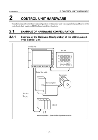
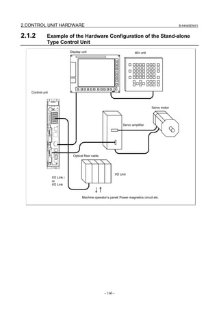
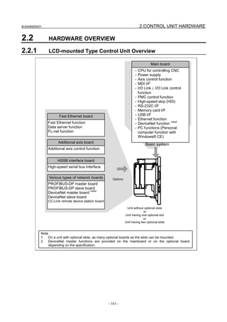
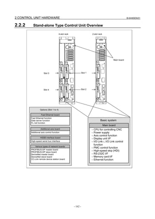


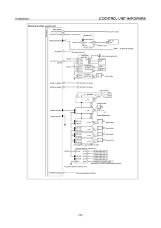
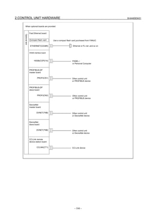


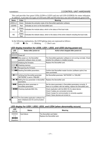


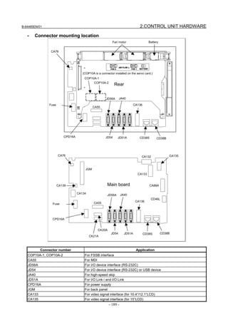


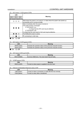


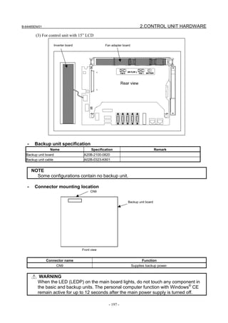


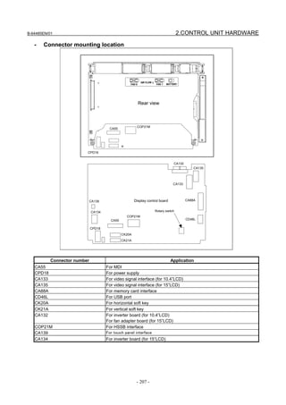

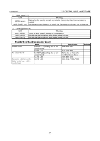
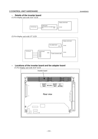
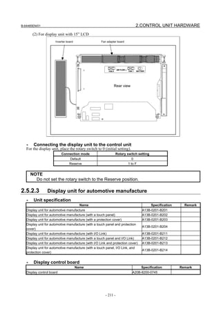


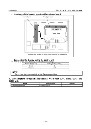
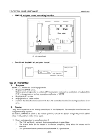
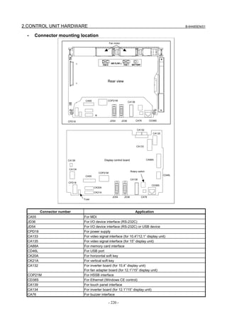


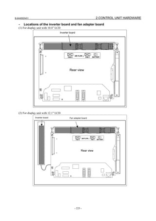


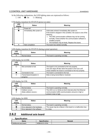
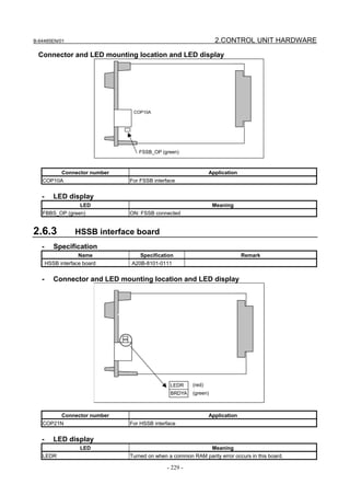
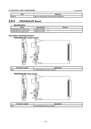


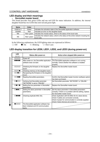

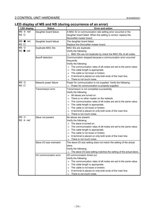
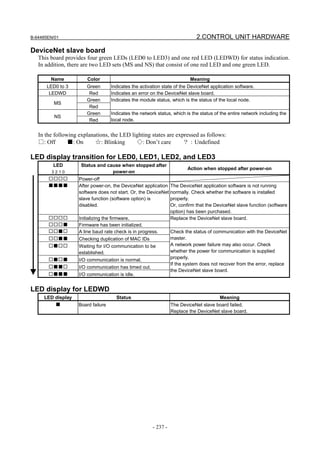


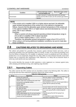


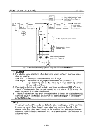
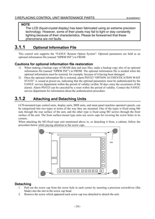


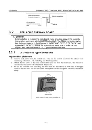


![3.REPLACING CONTROL UNIT MAINTENANCE PARTS B-64485EN/01
3.3 REPLACING THE DISPLAY CONTROL BOARD FOR THE
DISPLAY UNIT
Replacement procedure
1) Detach each cable from the display unit. While referencing Subsection 3.1.2, “Attaching and
Detaching Units”, take out the display unit from the cabinet.
2) [Display unit (with 10.4” LCD unit A)]
Remove the screws from the cover and detach the cover. If the display unit is a type having a touch
panel, remove the cable from the touch panel control board before detaching the cover.
[Other types of display units]
Remove the two screws from the lower section of the case unit. While pushing down the claws in the
upper section, take out the case unit. The structure is such that the screws will not come off the case
unit. Note that the fan motor need not be removed. While unlatching the claws from the metal bases
on both sides in the upper section of the case unit, pull out the case unit.
Screws (4 places)
Display unit (with 10.4” LCD unit A)
Claws
Screws.
Note) The structure is such that the screws will not come off the case.
Other display units
3) Remove the cable from each connector on the display control board. Also remove the screws
fastening the display control board.
- 256 -](https://image.slidesharecdn.com/b-64485en01-121129013453-phpapp02/85/B-64485-en-01-278-320.jpg)
![B-64485EN/01 3.REPLACING CONTROL UNIT MAINTENANCE PARTS
4) Detach the display control board by pulling it down because the display control board and inverter
board are connected using the connector CA132 (for the inverter board).
5) Move cards and modules (if any) from the detached display control board to another (replacing)
display control board, and attach the replacing display control board.
6) Connect the display control board to the inverter board and fasten it with screws. Re-attach each
cable to the display control board while exercising care not to attach them incorrectly.
7) [For display unit (with 10.4" LCD unit A)]
Mount the cover using screws. If the display unit is a type having a touch panel, re-attach the
cable to the touch panel controller board.
[For other display units]
Place the case unit in such way that its screws and latches align with their respective positions
and push it in slowly. After making sure that the case unit is latched securely, tighten the case
unit screws. Also make sure that the fan motor is connected securely.
8) While referencing Subsection 3.1.2, “Attaching and Detaching Units”, attach the display unit to the
cabinet. Re-attach the cables to the display unit. Be careful not to attach them incorrectly.
NOTE
Once the display control board on a display unit with a touch panel is replaced,
the touch panel needs to be calibrated. See Section 3.14 for explanations about
how to adjust the touch panel.
3.4 REPLACING LCD UNITS
3.4.1 LCD-mounted Type Control Unit (8.4” LCD Unit and 10.4”
LCD Unit)
CAUTION
Before starting to replace the main board, make a backup copy of the contents
(parameters, programs, etc.) of SRAM in the CNC. The SRAM contents may be
lost during replacement. See Chapter 5, “INPUT AND OUTPUT OF DATA”, and
Appendix C, “BOOT SYSTEM” for explanations about how to make backup
copies. Also see Subsection 3.1.1, “Optional Information File”.
Replacement procedure
1) Remove the screws from the lower section of the case unit and pull it out while unlatching claws
from the upper section.
Unlatch the claw from each metal base.
Remove screws (2 places).
Note) The structure is such that the screws will not come off the case.
2) Detach the cable from each connector on the main board. Also remove the fastening screws.
- 257 -](https://image.slidesharecdn.com/b-64485en01-121129013453-phpapp02/85/B-64485-en-01-279-320.jpg)
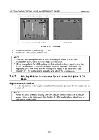


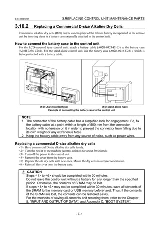

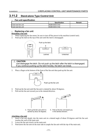


![3.REPLACING CONTROL UNIT MAINTENANCE PARTS B-64485EN/01
2) Applying the protection sheet
<1> Fold the tab over the front side (the side opposite to the backing sheet).
Fold
<2> Peel off the backing sheet.
<3> Position the sheet, then attach the upper and lower sides of the sheet first. Check that the sides
of the protection sheet do not touch the escutcheon.
OK NG
<4> Attach the right and left sides of the protection sheet while pushing out air between the touch
panel and protection sheet.
→ With part of the protection sheet kept stuck to the touch panel, do not attempt to correct
the position of the protection sheet by pulling the sheet.
<5> Press the adhesive parts of the four sides, and attach the entire sheet completely.
→ Check that the four corners and four sides of the protection sheet do not float.
(3) Checks after replacement
<1> Check that there is no wrinkle on the surface of the protection sheet.
<2> After power-on, check that there is no touch panel portion kept pressed.
<3> Press the touch panel, and check that correct operation takes place.
3.14 TOUCH PANEL CALIBRATION
- Conditions that require calibration
Touch panel calibration is needed under the following conditions:
1. The LCD mounted type control unit with a touch panel or the display unit with a touch panel was
replaced.
2. The main board on the LCD mounted type control unit with a touch panel or the display control
board on the display unit with a touch panel was replaced.
3. The touch panel control board was replaced.
4. Memory all clear was performed.
- Related Parameters
#7 #6 #5 #4 #3 #2 #1 #0
3113 DCL
[Input type] Parameter input
[Data type] Bit
#5 DCL The touch panel compensation screen is:
0: Disabled.
1: Enabled.
Set this parameter to 0 usually. Touch panel compensation becomes necessary only when
the panel is replaced or memory all clear operation is performed. Set this parameter to 1
only when performing touch panel compensation. Upon completion of compensation, set
this parameter to 0.
- 280 -](https://image.slidesharecdn.com/b-64485en01-121129013453-phpapp02/85/B-64485-en-01-302-320.jpg)
![B-64485EN/01 3.REPLACING CONTROL UNIT MAINTENANCE PARTS
#7 #6 #5 #4 #3 #2 #1 #0
3119 TPA DDS
[Input type] Parameter input
[Data type] Bit
NOTE
When this parameter is set, the power must be turned off before
operation is continued.
#2 DDS The touch panel is:
0: Enabled.
1: Disabled.
Set this parameter to 1 when disabling the touch panel temporarily, for example, at
start-up time.
- Touch panel calibration method
NOTE
How to calibrate the touch panel used with the display unit for the LCD-mounted
control unit (with personal computer function with Windows® CE) and the
stand-alone control unit (with personal computer function with Windows® CE) or
the display unit for automobile manufacturers is explained later.
Calibration procedure
<1> Enable the touch panel calibration screen.(Set bit 5 (DCL) of parameter No. 3113 to 1.)
<2> Press function key .
<3> Press the continuous menu key several times. The [TOUCH PANEL] soft key is displayed.
<4> Press the [TOUCH PANEL] soft key then the [(OPRT)] soft key. The [TP CAL] soft key is
displayed.
- 281 -](https://image.slidesharecdn.com/b-64485en01-121129013453-phpapp02/85/B-64485-en-01-303-320.jpg)
![3.REPLACING CONTROL UNIT MAINTENANCE PARTS B-64485EN/01
<5> Pressing the [TP CAL] soft key causes a full-screen touch panel calibration screen to appear.
<6> Click the 9 calibration points with a stylus pen. The marker of a normally clicked point changes
from "+" to "o". If you fail to click right on a "+" mark, the message "Your stylus pen is not right on
a "+" mark. Click again." appears.
<7> After clicking all 9 calibration points, clicking the key completes calibration. To quit or retry
calibration, click the key. The previous screen appears again. Before clicking 9 calibration
points, clicking the key aborts calibration.
<8> When calibration ends normally, the message "Calibration ended" appears.
<9> After completing calibration, disable the touch panel calibration screen (by resetting the DCL
parameter (bit 5 of parameter No. 3113) to 0) to prevent operation mistake.
- Touch panel calibration method (for LCD-moutend type control unit
(personalcomputer function with Windows® CE) and display unit for
stand-alone type control unit (personalcomputer function with Windows® CE))
Open the control panel and start the stylus.
Make calibration as directed in the window.
- Touch panel calibration method (for display unit for automotive manufacture)
1. Press the ALT-O key to display the following function menu.
2. Select [Stylus] to display the calibration screen.
- 282 -](https://image.slidesharecdn.com/b-64485en01-121129013453-phpapp02/85/B-64485-en-01-304-320.jpg)


![4.MAINTENANCE OF THE OTHER UNITS B-64485EN/01
For details of the system relay area, refer to the FANUC Series 30i/31i/32i-MODEL B PMC
Programming Manual (B-64513EN).
[Reference] System relay area related to a status alarm
Channel 1 Channel 2 7 6 5 4 3 2 1 0
R9268(Z268) R9276(Z276) Status Type
R9269(Z269) R9277(Z277) Group number
R9270(Z270) R9278(Z278) Slot number
R9271(Z271) R9279(Z279) Alarm information number
R9272(Z272) R9280(Z280)
Y address number
R9273(Z273) R9281(Z281)
R9274(Z274) R9282(Z282) PMC path
R9275(Z275) R9283(Z283) Alarm data
[Reference] Simple description of signals
Name Description
Status Indicates that a status alarm occurs when this signal is set to 1.
Type Indicates the type of status alarm.
0: DO alarm (such as a ground fault), 1: Other than a DO alarm (such as a DO
common voltage error)
Group number Outputs a group number (0 to 23).
Slot number Outputs a numeric value 0 to 31, which indicates slot number 1 to 32.
Alarm information number Outputs the position of the alarm information corresponding to the alarm which
occurs (byte position in the slot).
Y address number Outputs the Y address number of the relevant DO signal. Valid when the PMC
path value is other than 0.
PMC path Outputs the PMC path at the Y address assigned to the relevant DO signal.
Outputs 0 if no address is assigned to the DO signal.
Alarm data Outputs information on the alarm which occurs. Outputs 1 to the bit corresponding
to the alarm which occurs.
4.2.2 I/O Module for Connector Panel [Supporting I/O Link i]
- Specification
Name Ordering specifications Specification
I/O module for connector panel
A03B-0824-C001 DI/DO : 24/16
(basic module)
I/O module for connector panel DI/DO : 24/16
A03B-0824-C002
(extension module A) With MPG interface
I/O module for connector panel DI/DO : 24/16
A03B-0824-C003
(extension module B) Without MPG interface
I/O module for connector panel DO : 16
A03B-0824-C004
(extension module C) 2A output module
I/O module for connector panel
A03B-0824-C005 Analog input module
(extension module D)
1A
Fuse (spare parts) A03B-0815-K002
(For basic module)
20 mm long
Flat cable between modules A03B-0815-K100
Suitable for a module interval of 32 mm
- 286 -](https://image.slidesharecdn.com/b-64485en01-121129013453-phpapp02/85/B-64485-en-01-308-320.jpg)


![B-64485EN/01 4.MAINTENANCE OF THE OTHER UNITS
- Correspondence between slot numbers and intra-slot byte addresses
The table below lists the slot number and intra-slot byte address for this module.
Slot number Intra-slot byte address DO address Location
1 0 Yn1 Basic module
1 1 Yn1+1 Basic module
2 0 Yn2 Extension module 1
2 1 Yn2+1 Extension module 1
3 0 Yn3 Extension module 2
3 1 Yn3+1 Extension module 2
4 0 Yn4 Extension module 3
4 1 Yn4+1 Extension module 3
4.2.3 I/O Module for Operator’s Panel (Supporting Matrix Input)
[Supporting I/O Link i]
- Specification
Name Specification Remark
I/O module for operator’s panel A03B-0824-K200
Fuse (spare parts) A03B-0815-K001 1A
- Connector, LED, and fuse locations
LINK LED (green) FUSE LED (red)
JD1A
ALM LED (red) JD1B
JA3
Fuse
CE53 CE54 CPD1
Connector number Use
JD1A Second I/O Link i stage
JD1B First I/O Link i stage
JA3 Manual pulse generator
CPD1 24VDC input/output
CE53 DI/DO connector 1
CE54 DI/DO connector 2
- 289 -](https://image.slidesharecdn.com/b-64485en01-121129013453-phpapp02/85/B-64485-en-01-311-320.jpg)
![4.MAINTENANCE OF THE OTHER UNITS B-64485EN/01
- LED
The I/O module for operator’s panel incorporates a green LED, “LINK”, and two red LEDs, “ALM” and
“FUSE” in above figure.
See Subsection 4.2.1 for descriptions of the correspondence between the on/off state of each LED and the
status of the I/O module for operator’s panel.
- Correspondence between slot numbers and intra-slot byte addresses
The table below lists the slot number and intra-slot byte address for this module.
With this module, DO alarms (such as ground fault) are detected for each byte separately.
Information output to the system relay area
Description
Slot number Alarm information number Alarm data bit 0 data
1 0 1 Yn1 error
1 1 1 Yn1+1 error
1 2 1 Yn1+2 error
1 3 1 Yn1+3 error
1 4 1 Yn1+4 error
1 5 1 Yn1+5 error
1 6 1 Yn1+6 error
4.2.4 Connection of I/O Module for Operator's Panel and I/O
Module for Power Magnetics Cabinet [Supporting I/O Link i]
・ Specification
Item Ordering specifications Remarks
DI : 48 points
I/O module for operator’s panel
A03B-0824-K202 DO : 32 points
(with MPG interface)
With MPG interface
DI : 48 points
I/O module for power magnetics cabinet
A03B-0824-K203 DO : 32 points
(without MPG interface)
Without MPG interface
Fuse (spare parts) A03B-0815-K001 1A
- 290 -](https://image.slidesharecdn.com/b-64485en01-121129013453-phpapp02/85/B-64485-en-01-312-320.jpg)
![B-64485EN/01 4.MAINTENANCE OF THE OTHER UNITS
- Connector, LED, and fuse locations
LINK LED (green) FUSE LED (red)
JD1A
ALM LED (red) JD1B
JA3
Fuse
CE56 CE57 CPD1
Connector number Use
JD1A Second I/O Link i stage
JD1B First I/O Link i stage
JA3 Manual pulse generator
CPD1 24VDC input/output
CE56 DI/D connector 1
CE57 DI/DO connector 2
- LED
The I/O module for operator’s panel incorporates a green LED, “LINK”, and two red LEDs, “ALM” and
“FUSE” in above figure.
See Subsection 4.2.1 for descriptions of the correspondence between the on/off state of each LED and the
status of the I/O module for operator’s panel.
- Correspondence between slot numbers and intra-slot byte addresses
The table below lists the slot number and intra-slot byte address for this module.
Slot number Alarm information number Address of the DO driver which detects an error
1 0 Yn1
1 1 Yn1+1
1 2 Yn1+2
1 3 Yn1+3
4.2.5 I/O Module Type-2 for Connector Panel [Supporting I/O Link i]
- Specification
Item Ordering specifications Specification
I/O module type-2 for connector panel A03B-0824-C040 DI/DO=48/32
(basic module B1) With MPG interface
I/O module type-2 for connector panel A03B-0824-C041 DI/DO=48/32
(basic module B2) Without MPG interface
- 291 -](https://image.slidesharecdn.com/b-64485en01-121129013453-phpapp02/85/B-64485-en-01-313-320.jpg)

![B-64485EN/01 4.MAINTENANCE OF THE OTHER UNITS
Address of the DO driver
Slot number Alarm information number Location
which detects an error
1 1 Yn1+1 Basic module
1 2 Yn1+2 Basic module
1 3 Yn1+3 Basic module
2 0 Yn2 Extension module
2 1 Yn2+1 Extension module
2 2 Yn2+2 Extension module
2 3 Yn2+3 Extension module
4.2.6 Terminal Type I/O Module [Supporting I/O Link i]
- Specification
Item Ordering specifications Specification
Basic module A03B-0823-C011 DI/DO: 24/16
DI/DO : 24/16
Extension module A A03B-0823-C012
With MPG interface
DI/DO : 24/16
Extension module B A03B-0823-C013
Without MPG interface
DO : 16
Extension module C A03B-0823-C014
2-A output module
Extension module D A03B-0823-C015 Analog input module
Extension module E A03B-0823-C016 Analog output module
Fuse (spare parts) A03B-0823-K001 2A (for basic module)
Spare terminal block set
Cable-side terminal block set (including each
(for basic module and extension A03B-0823-K020
of T1 through T4)
module A/B)
Spare terminal block set Cable-side terminal block set (including each
A03B-0823-K011
(for extension module C) of T1 and T2)
Spare terminal block set Cable-side terminal block set (including each
A03B-0823-K012
(for extension module D) of T1 and T2)
Spare terminal block set Cable-side terminal block set (including each
A03B-0823-K013
(for extension module E) of T1 and T2)
Cable length: 100 mm, 52 pins
Inter-module cable A A03B-0823-K100
Used for extension module connection
CAUTION
The spare terminal board set is a replacement set for a cable-side terminal board
supplied with the main unit.
- 293 -](https://image.slidesharecdn.com/b-64485en01-121129013453-phpapp02/85/B-64485-en-01-315-320.jpg)

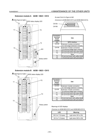


![4.MAINTENANCE OF THE OTHER UNITS B-64485EN/01
CAUTION
2 Disconnection detection is performed by monitoring, with an output element in the
module, the current flowing through a load when DO output is ON. When the
detected current value is about 100 mA or less, disconnection detection is
assumed. So, when a device (such as an LED) with a small load current is
connected, the DO alarm state results, assuming disconnection detection. Unlike
the other protection functions, however, this function does not turn off DO output.
If a connection is reactivated after the state of disconnection is once set,
disconnection detection is canceled without restarting the system.
- Rotary switch
CAUTION
When replacing extension modules, set the rotary switch on a replacing module in
the same manner as for the replaced module.
Re-setting the rotary switch on each extension module can be used to connect them by skipping other
modules. For details, see descriptions of the rotary switch in Subsection 4.2.2, “I/O module for connector
panel”.
- Correspondence between slot numbers and intra-slot byte addresses
The table below lists the slot number and intra-slot byte address for this module.
Slot number Intra-slot byte address DO address Location
1 0 Yn1 Basic module
1 1 Yn1+1 Basic module
2 0 Yn2 Extension module 1
2 1 Yn2+1 Extension module 1
3 0 Yn3 Extension module 2
3 1 Yn3+1 Extension module 2
4 0 Yn4 Extension module 3
4 1 Yn4+1 Extension module 3
4.2.7 I/O Link Connection Unit [Supporting I/O Link i]
Specification
Name Specification
I/O Link connection unit A02B-0333-C250
Fuse 1A (spare parts, 1 piece) A03B-0815-K001
- 298 -](https://image.slidesharecdn.com/b-64485en01-121129013453-phpapp02/85/B-64485-en-01-320-320.jpg)

![4.MAINTENANCE OF THE OTHER UNITS B-64485EN/01
CAUTION
The I/O Link connection unit has two I/O Link channels, each having to be
supplied with 24 V.
If the LED “LINK1” neither steadily lights nor blinks, check for 24 V on the
connector CP1.
If the LED “LINK2” neither steadily lights nor blinks, check for 24 V on the
connector CP2
4.2.8 Standard Machine Operator's Panel [Supporting I/O Link i]
- Specification
Name Specification
Standard machine operators panel Main panel A02B-0323-C231
Standard machine operators panel Sub panel A A02B-0236-C232
Standard machine operators panel Sub panel D A02B-0236-C244
Set of transparent key tops (55 key tops) A02B-0236-K170
Set of blank key tops (55 key tops) A02B-0236-K171
Set of symbol English key tops (34 labeled key tops + 21 blank key tops) A02B-0236-K174
Set of blank key tops (100 red blank key tops) A02B-0236-K175
Set of blank key tops (100 green blank key tops) A02B-0236-K176
Set of blank key tops (100 blue blank key tops) A02B-0236-K177
Set of blank key tops (100 yellow blank key tops) A02B-0236-K178
Screw caps (with 5 pieces included) A02B-0319-K191
Fuse 1A (spare parts) A03B-0815-K001
- 300 -](https://image.slidesharecdn.com/b-64485en01-121129013453-phpapp02/85/B-64485-en-01-322-320.jpg)


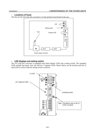
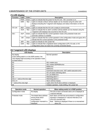


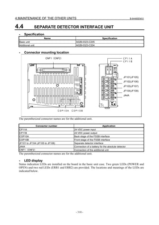


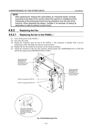


![4.MAINTENANCE OF THE OTHER UNITS B-64485EN/01
CAUTION
• Purchase the battery from FANUC because it is not commercially available. It is
therefore recommended that you have a backup battery.
• When the built-in battery is used, do not connect BATL (B3) of connector
CXA2A/CXA2B. Also, do not connect two or more batteries to the same BATL
(B3) line. These connections are dangerous because battery output voltages
may be short-circuited, causing the batteries to overheat.
• Install the battery in the servo amplifier in a direction that allows slack in the
cable. If the battery cable is under tension, a bad connection may occur.
• If the +6 V pin and 0 V pin are short-circuited, the battery may overheat, blow
out, or catch fire, or the absolute position information in the absolute
Pulsecoders may be lost.
• When inserting the connector, align it to the connector pins.
[Connecting the battery]
The battery for the βiSV4 and βiSV20 series amplifiers is mounted in the battery case on the underside of
each of the amplifiers.
The battery for the other βi series amplifiers and the αi series amplifiers is mounted at the front of each of
the amplifiers.
[αi series][βi series βi SV40, βi SV80] [βi series βi SV4, βi SV 20]
Insertion direction Cable side Insertion direction
Cable side
Red: +6 V Red: +6 V
Connector Black: 0 V Connector Black: 0 V
CX5X CX5X
Battery
+6 V Battery case +6 V
0V Battery 0V
Battery case
[Battery sets and outlines]
Battery ordering Battery case ordering
Applicable servo amplifier Outline
drawing number drawing number
αi series 60/90 mm width A06B-6114-K505
A06B-6114-K504 αi series 150/300 mm width A06B-6114-K506
βi series βi SV (two-axis model) A06B-6114-K505
βi series βiSV4, βiSV20 A06B-6093-K002
A06B-6093-K001
βi series βiSV40, βiSV80 A06B-6093-K002
Used batteries
Old batteries should be disposed as "INDUSTRIAL WASTES" according to the regulations of the
country or autonomy where your machine has been installed.
- 318 -](https://image.slidesharecdn.com/b-64485en01-121129013453-phpapp02/85/B-64485-en-01-340-320.jpg)
![B-64485EN/01 5.INPUT AND OUTPUT OF DATA
5 INPUT AND OUTPUT OF DATA
After you change a FROM/SRAM module, you must set various data again. This chapter explains how to
input data (such as parameters, part programs, and tool offset values) to external I/O devices (such as a
floppy disk drive) and to output it from them.
5.1 SETTING PARAMETERS FOR INPUT/OUTPUT ........................................................................319
5.2 INPUTTING/OUTPUTTING DATA ...............................................................................................320
5.3 AUTOMATIC DATA BACKUP......................................................................................................327
5.1 SETTING PARAMETERS FOR INPUT/OUTPUT
Setting procedure of parameters
Parameter writing is enabled with following steps 1 to 3.
1 Set to MDI mode or emergency stop state.
2 Press function key several times or press soft key [SETTING] to display SETTING
(HANDY) screen.
3 Set the cursor to PARAMETER WRITE and, press and keys in this order. Here alarm
100 will be displayed.
4 Press function key several times to display the following screen.
PARAMETER (SETTING) O1234 N12345
0000 SEQ INI ISO TVC
0 0 0 0 0 0 0 0
0001 FCV
0 0 0 0 0 0 0 0
0012 RMV MIR
X 0 0 0 0 0 0 0 0
Y 0 0 0 0 0 0 0 0
Z 0 0 0 0 0 0 0 0
B 0 0 0 0 0 0 0 0
0020 I/O CHANNEL To make the cursor
display in bit unit,
press the cursor key
S 0 T0000 or .
REF **** *** *** 10: 15: 30
[ F SRH ][ READ ][ PUNCH ][DELETE ][ ]
5 Press soft key [(OPRT)] and the following operation menu is displayed.
<1> Soft key [NO. SRH] : Searched by number.
Examination) Parameter number → [NO. SRH].
<2> Soft key [ON : 1] : Item with cursor position is set to 1 (bit parameter)
<3> Soft key [OFF : 0] : Item with cursor position is set to 0 (bit parameter)
<4> Soft key [+INPUT] : Input value is added to the value at cursor (word type)
<5> Soft key [INPUT] : Input value is replaced with the value at cursor (word type)
<6> Soft key [READ] : Parameters are input from reader/puncher interface.
<7> Soft key [PUNCH] : Parameters are output to reader/puncher interface.
- 319 -](https://image.slidesharecdn.com/b-64485en01-121129013453-phpapp02/85/B-64485-en-01-341-320.jpg)


![5.INPUT AND OUTPUT OF DATA B-64485EN/01
Set value Input/output device
FANUC PPR
6
FANUC SYSTEM P-MODEL G, FANUC SYSTEM P-MODEL H
0103 Baud Rate
1: 50 7: 600 11: 9600
3: 110 8: 1200 12: 19200 [BPS]
4: 150 9: 2400
6: 300 (*)10: 4800
#7 #6 #5 #4 #3 #2 #1 #0
0139 ISO
ISO 0: Output with ASCII code
1: Output with ISO code (memory card)
WARNING
1 Unless data is input using ASCII codes, set this parameter to 1 to
input or output data using ISO codes.
2 Data input/output with ASCII codes is dangerous because parity
information is not included and a data error during the data
input/output is not detected.
3 DNC operation from a memory card also must set the parameter to
1, and execute DNC operation by ISO code. ASCII codes is
dangerous because parity information is not included and a data
error during the data input is not detected.
NOTE
A tool (FANUC ISO Converter) for converting data from ASCII code
to ISO code on a commercial PC is available from FANUC.
#7 #6 #5 #4 #3 #2 #1 #0
11505 ISU
ISU 0: Output with ASCII code
1: Output with ISO code (USB memory)
WARNING
1 Unless data is input using ASCII codes, set this parameter to 1 to
input or output data using ISO codes.
2 Data input/output with ASCII codes is dangerous because parity
information is not included and a data error during the data
input/output is not detected.
NOTE
A tool (FANUC ISO Converter) for converting data from ASCII code
to ISO code on a commercial PC is available from FANUC.
5.2.2 Outputting CNC Parameters
1 Enter EDIT mode or the emergency stop condition.
2 Press function key and soft key [PARAMETER] to select a parameter screen.
- 322 -](https://image.slidesharecdn.com/b-64485en01-121129013453-phpapp02/85/B-64485-en-01-344-320.jpg)
![B-64485EN/01 5.INPUT AND OUTPUT OF DATA
3 Press soft key [(OPRT)] and continuous menu key .
4 Press soft key [PUNCH] and [EXEC],and the parameters are started to be output.
5.2.3 Outputting Pitch Error Compensation Amount
1 Select EDIT mode.
2 Press the function key and continuous menu key several times, then press [PITCH] to
select the pitch error compensation setting screen.
3 Press soft key [(OPRT)] and continuous menu key .
4 Press soft key [PUNCH] and [EXEC], then pitch error compensation amount is started to be output.
5.2.4 Outputting Custom Macro Variable Values
When custom macro function is equipped, values of variable No. 500 and later are output.
1 Press function key .
2 Press continuous menu key and soft key [MACRO] to select custom macro variable screen.
3 Press soft key [(OPRT)] and then continuous menu key .
4 Press soft key [PUNCH] and [EXEC], then custom macro variable values are output.
5.2.5 Outputting Tool Compensation Amount
1 Select EDIT mode.
2 Press function key and soft key [OFFSET] to display the tool compensation amount screen.
3 Press [(OPRT)] key and continuous menu key .
4 Press soft key [PUNCH] an [EXEC] key, and the tool compensation amount is started to be output.
5.2.6 Outputting Part Program
1 Confirm the following parameters. If this parameter is set to 1, rather than the value indicated by l,
change to MDI mode and then reset to 0.
However, if you changed the parameter setting, restore the original value after finishing this work.
#7 #6 #5 #4 #3 #2 #1 #0
3202 NE9 NE8
NE9(*) 0: Programs of 9000s are edited.
1: Programs of 9000s can be protected. (Protected programs are not output.)
NE8 (*) 0: Programs of 8000s are edited.
1: Programs of 8000s can be protected.
(Protected programs are not output.)
2 Select EDIT mode.
3 Press function key and press soft key [PROGRAM] to display program text.
4 Press [(OPRT)] key and press continuous menu key .
5 Input a program number to be output. To output all programs input as:
6 Press [PUNCH] and [EXEC] key, then program output is started.
- 323 -](https://image.slidesharecdn.com/b-64485en01-121129013453-phpapp02/85/B-64485-en-01-345-320.jpg)
![5.INPUT AND OUTPUT OF DATA B-64485EN/01
5.2.7 Inputting CNC Parameters
1 Set to the emergency stop state.
2 Confirm that the patameters required to input data is correct.
In addition, (*) indicates the standard setting for input/output devices made by FANUC. Change
these settings according to the unit you actually use.
<1> Press function key several times, and press [SETING] to display SETTING screen.
<2> Confirm that PARAMETER WRITE=1.
<3> Press function key to select the parameter screen.
<4>
0020 Selection of I/O channel
(*) 0: Channel 1 (JD56A of mother board)
1: Channel 1 (JD56A of mother board)
2: Channel 2 (JD36A of mother board)
4: Memory card interface
17 : USB memory interface
<5>
#7 #6 #5 #4 #3 #2 #1 #0
0101 NFD ASI SB2
NFD 0: Feed is output when punching out.
1: Feed is not output when punching out.
ASI 0: EIA or ISO code is used.
1: ASCII code is used.
SB2 0: No. of stop bits is 1.
(*) 1: No. of stop bits is 2.
<6>
0102 Specification number of I/O device
Set value Input/output device
0 RS-232-C (Used control codes DC1 to DC4)
1 FANUC CASSETTE ADAPTOR 1 (FANUC CASSETTE B1/B2)
2 FANUC CASSETTE ADAPTOR 3 (FANUC CASSETTE F1)
FANUC PROGRAM FILE Mate, FANUC FA Card Adaptor
3 FANUC FLOPPY CASSETTE ADAPTOR, FANUC Handy File
FANUC SYSTEM P-MODEL H
4 RS-232-C (Not used control codes DC1 to DC4)
5 Portable tape reader
FANUC PPR
6
FANUC SYSTEM P-MODEL G, FANUC SYSTEM P-MODEL H
<7>
0103 Baud rate
1: 50 7: 600 11: 9600
3: 110 8: 1200 12: 19200 [BPS]
4: 150 9: 2400
6: 300 (*)10: 4800
3 Press continuous menu key .
4 Press soft key [READ] and [EXEC]. Then input of parameters are started.
- 324 -](https://image.slidesharecdn.com/b-64485en01-121129013453-phpapp02/85/B-64485-en-01-346-320.jpg)
![B-64485EN/01 5.INPUT AND OUTPUT OF DATA
5 Upon completion of parameter input, turn off the power then turn on the power again.
6 Alarm 300 is issued if the system employs an absolute pulse coder. In such a case, perform reference
position return again.
#7 #6 #5 #4 #3 #2 #1 #0
0139 ISO
ISO 0: Output with ASCII code
1: Output with ISO code (memory card)
WARNING
1 Unless data is input using ASCII codes, set this parameter to 1 to
input or output data using ISO codes.
2 Data input/output with ASCII codes is dangerous because parity
information is not included and a data error during the data
input/output is not detected.
3 DNC operation from a memory card also must set the parameter to
1, and execute DNC operation by ISO code. ASCII codes is
dangerous because parity information is not included and a data
error during the data input is not detected.
NOTE
A tool (FANUC ISO Converter) for converting data from ASCII code
to ISO code on a commercial PC is available from FANUC.
#7 #6 #5 #4 #3 #2 #1 #0
11505 ISU
ISU 0: Output with ASCII code
1: Output with ISO code (USB memory)
WARNING
1 Unless data is input using ASCII codes, set this parameter to 1 to
input or output data using ISO codes.
2 Data input/output with ASCII codes is dangerous because parity
information is not included and a data error during the data
input/output is not detected.
NOTE
A tool (FANUC ISO Converter) for converting data from ASCII code
to ISO code on a commercial PC is available from FANUC.
5.2.8 Inputting Pitch Error Compensation Amount
1 Release the emergency stop and select EDIT mode.
2 Confirm that PARAMETER WRITE=1 on the setting screen.
3 Press function key and soft key [PROGRAM] to display program contents.
4 Press function key several times, soft key [PARAM], continuous menu key and
[PITCH] to select the screen for pitch error compensation amount.
5 Press the function key and continuous menu key several times, then press [PITCH] to
select the pitch error compensation setting screen.
- 325 -](https://image.slidesharecdn.com/b-64485en01-121129013453-phpapp02/85/B-64485-en-01-347-320.jpg)
![5.INPUT AND OUTPUT OF DATA B-64485EN/01
6 Press soft key [(OPRT)] and continuous menu key .
7 Press soft key [READ] and [EXEC], then the pitch error compensation amount is started to be input.
8 After data has been input, press function key twice to display the SETTING screen and return
the PARAMETER WRITE to 0.
5.2.9 Inputting Custom Macro Variable Values
* If the system is equipped with the custom macro fucntion, input the variable values.
1 Select EDIT mode.
2 Press function key then soft key [PROGRAM] to display program contents.
3 Press the function key and press continuous menu key several times, then press
[PITCH] to select the pitch error compensation setting screen.
4 Press soft key [(OPRT)] and continuous menu key .
5 Press soft key [READ] and [EXEC], then the pitch error compensation amount is started to be input.
5.2.10 Inputting Tool Compensation Amount
1 Select EDIT mode.
2 Turn off the program protect (KEY=1).
3 Press function key , and soft key [OFFSET] to display the tool compensation amount screen.
4 Press soft key [(OPRT)] and continuous menu key .
5 Press [READ] key and [EXEC] key and data input is started.
5.2.11 Inputting Part Programs
Confirm the following parameters. If the setting is different from the value indicated by (*), reset to the
specified value only during this work. (Change it in MDI mode).
#7 #6 #5 #4 #3 #2 #1 #0
3201 NPE RAL
NPE When programs are registered in part program storage area, M02,M30 and M99 are:
0: Regarded as the end of program.
(*) 1: Not regarded as the end of porgram.
RAL When programs are registered:
(*) 0: All programs are registered.
1: Only one program is registered.
#7 #6 #5 #4 #3 #2 #1 #0
3202 NE9 NE8
NE9 (*) 0: Programs of 9000s can be edited.
1: Programs of 9000s are protected.
NE8 (*) 0: Programs of 8000s can be edited.
1: Programs of 8000s are protected.
* For PPR, item 4 is not required.
1 Confirm that mode is EDIT mode.
2 Turn off the program protect (KEY3=1).
- 326 -](https://image.slidesharecdn.com/b-64485en01-121129013453-phpapp02/85/B-64485-en-01-348-320.jpg)
![B-64485EN/01 5.INPUT AND OUTPUT OF DATA
3 Press function key and press soft key [PROGRAM] to select a part program file.
4 Press soft key [READ] and [EXEC], then data input is started.
5.3 AUTOMATIC DATA BACKUP
It is possible to back up data held in the CNC’s FROM/SRAM by storing it automatically in the FROM,
which requires no battery and to restore the baked-up data as required. If data is lost from the CNC due to
unforeseen circumstances, this function can be used to restore the data easily.
Also, it is possible to hold up to three occurrences of backup data. With this function, the CNC data can
be quickly switched to a post-machine adjustment state or an arbitrary backup state.
SRAM (requires batteries)
Backup All types of data, such as
parameters and offset data, in
SRAM
FROM (requires no battery)
NC programs and directory
information
Backup data 1
Backup data 2
Restore
Backup data 3
Explanation
- Data to be backed up
Data in the CNC is backed up by storing it in the FROM, which requires no battery.
• NC programs and directory information held in the FROM (which requires no battery)
• Various types of data, such as parameters and offset values, held in the SRAM (which requires
batteries)
Setting bit 2 (AAP) of parameter No.10340 to 1 enables NC programs and directory information in the
FROM to be backed up. Set this parameter only when necessary, because the required backup time and
data storage size vary depending on the size of the programs.
Setting parameter No. 10342 enables up to 3 occurrences of backup data to be held.
- Backup modes
The following three backup modes are available.
1. Automatic backup occurring every time the power is turned on
2. Automatic backup occurring at intervals of a specified number of days when the power is turned on
3. Backup started manually at an emergency stop
- Automatic backup occurring every time the power is turned on
Data in the CNC can be backed up automatically when the power is turned on.
This mode can be used by:
• Setting bit 0 (ABP) of parameter No. 10340 to 1
• Setting parameter No. 10342 to 1 or greater
- 327 -](https://image.slidesharecdn.com/b-64485en01-121129013453-phpapp02/85/B-64485-en-01-349-320.jpg)
![5.INPUT AND OUTPUT OF DATA B-64485EN/01
• Setting bit 2 (AAP) of parameter No. 10340 to 1 if also NC programs and directory information in
the FROM must be backed up
- Automatic backup occurring at intervals of a specified number of days when
the power is turned on
Data in the CNC can be backed up automatically when the power is turned on for the first time in a
specified number of days since the previous backup.
This mode can be used by:
• Selecting the first backup mode (automatic backup occurring every time the power is turned on)
• Setting parameter No. 10341 with a number of days at intervals of which automatic backup is to be
made cyclically
- Backup started manually at an emergency stop
Data in the CNC can be backed up by starting an appropriate procedure manually in an emergency stop
state. This mode makes it possible to back up data without turning off the power for the CNC at an
arbitrary timing, such as when machining has been set up or before a holiday.
This mode can be used by:
• Setting parameter No. 10342 to 1 or greater
• Setting bit 2 (AAP) of parameter No. 10340 to 1 if also NC programs and directory information in
the FROM must be backed up
[Backup procedure]
1. Put the machine in an emergency stop state.
2. Set bit 7 (EEB) of parameter No. 10340 to 1 to start backup. This parameter becomes 0 just after the
backup sequence has started.
3. The execution status of backup can be checked with No. 1016 on the diagnosis screen described
later.
NOTE
It takes time since the beginning of backup till the end of backup. So, if data being
backed up is updated, it is likely that a mismatch may occur between the original
data and backup data. When updating data in the CNC at an emergency stop,
watch the automatic data backup in-progress signal ATBK and perform
appropriate processing.
- Backup execution status
In the backup modes used at power-on time, 10 dots “.” are used to indicate the execution status of
backup. For example, the completion of backup is indicated with: “AUTO BACKUP : ……….END
The diagnosis screen can also be used to check the execution status of backup as follows:
• No.1016#0 (AEX): Backup in progress
• No.1016#6 (ACM): Backup completed
• No.1016#7 (ANG): Error during backup
• No.1016#1 (DT1), #2 (DT2), #3 (DT3): Updated data
- Write-protected backup data
Factory-set or post-adjustment machine status data can be held as write-protected backup data by
specifying the number of pieces of backup data to 2 or greater with parameter No. 10342. The first piece
of backup data is handled as write-protected backup data.
This function is enabled by:
• Setting bit 1 (ABI) of parameter No. 10340 to 1
• Setting parameter No. 10342 to 2 or greater
• Setting bit 2 (AAP) of parameter No. 10340 to 1 if also NC programs and directory information in
the FROM must be backed up
- 328 -](https://image.slidesharecdn.com/b-64485en01-121129013453-phpapp02/85/B-64485-en-01-350-320.jpg)
![B-64485EN/01 5.INPUT AND OUTPUT OF DATA
[Backup procedure]
1. Set bit 6 (EIB) of parameter No. 10340 to 1.
2. Turn the power for the CNC off and on again. When the power is turned on, the first piece of backup
data is updated automatically, and bit 6 (EIB) of parameter No. 10340 becomes 0.
The second and third pieces of backup data are updated each time another type of backup (automatic
backup occurring every time the power is turned on, automatic backup occurring at intervals of a
specified number of days when the power is turned on, or backup started manually at an emergency stop)
is made.
- Parity check
A parity check is made at backup. If a parity error is detected, the backup is not completed.
- Restoring backed-up data
With the BOOT SYSTEM, executing the following procedure can restore backed-up data from FROM.
1 From the BOOT’s TOP menu, select “7. SRAM DATA UTILITY”. The following menu appears.
Select ”3”.
SRAM DATA UTILITY
1.SRAM BACKUP ( CNC -> MEMORY CARD )
2.SRAM RESTORE ( MEMORY CARD -> CNC )
3.AUTO BKUP RESTORE ( FROM -> CNC )
4. END
2. From the menu below, select data and run restore.
AUTO BACKUP DATA RESTORE
1. BACKUP DATA1 yyyy/mm/dd **:**:**
2. BACKUP DATA2 yyyy/mm/dd **:**:**
3. BACKUP DATA3 yyyy/mm/dd **:**:**
4 END
3. Exit BOOT.
Signal
Automatic data backup in-progress signal ATBK<F0520.0>
[Classification] Output signal
[Function] This signal is "1" during automatic data backup. When updating data in the CNC at an
emergency stop, perform appropriate processing according to the state of this signal.
Signal address
#7 #6 #5 #4 #3 #2 #1 #0
F0520 ATBK
Parameter
#7 #6 #5 #4 #3 #2 #1 #0
10340 EEB EIB AAP ABI ABP
[Input type] Parameter input
[Data type] System-common type
#0 ABP Automatic data backup at power-on is:
0: Disabled.
1: Enabled.
- 329 -](https://image.slidesharecdn.com/b-64485en01-121129013453-phpapp02/85/B-64485-en-01-351-320.jpg)
![5.INPUT AND OUTPUT OF DATA B-64485EN/01
#1 ABI Overwrite-protected backup data is:
0: Regarded as invalid.
1: Regarded as valid.
#2 AAP Backup of NC programs and directory information in FROM is:
0: Disabled.
1: Enabled.
#6 EIB When the CNC is turned on next, overwrite-protected backup data is:
0: Not updated.
1: Updated.
NOTE
This parameter is valid when 2 or a greater value is set in
parameter No. 10342, and bit 1 (ABI) of parameter No. 10340 is set
to 1.
#7 EEB When an emergency stop occurs, a backup operation is:
0: Not performed.
1: Performed.
NOTE
This parameter is valid when 1 or a greater value is set in
parameter No. 10342.
10341 Interval at which automatic data backup is performed periodically
[Input type] Parameter input
[Data type] Word system-common type
[Unit of data] No unit
[Valid data range] 0 to 365
When automatic data backup is performed periodically, this parameter sets the interval as
the number of days. When the power is turned on after a set number of days has passed
from the date of the previous backup, a backup operation is performed. If 0 is set in this
parameter, this function is disabled.
10342 Number of backup data items
NOTE
When this parameter is set, the power must be turned off before
operation is continued.
[Input type] Parameter input
[Data type] Byte system-common type
[Unit of data] No unit
[Valid data range] 0 to 3
This parameter sets the number of backup data items. If 0 is specified, backup is not
performed.
Diagnosis display
This function enables the status of backup execution to be checked.
- 330 -](https://image.slidesharecdn.com/b-64485en01-121129013453-phpapp02/85/B-64485-en-01-352-320.jpg)
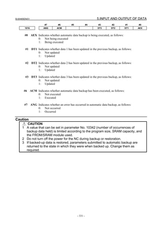
![6.INTERFACE BETWEEN CNC AND PMC B-64485EN/01
6 INTERFACE BETWEEN CNC AND PMC
This section briefly describes the PMC function. It also explains the CNC-PMC interface.
6.1 WHAT IS PMC? ...............................................................................................................................332
6.2 MULTI-PMC FUNCTION ...............................................................................................................336
6.3 PMC SPECIFICATIONS..................................................................................................................346
6.4 OPERATING THE PMC SCREEN..................................................................................................352
6.5 PMC DIAGNOSIS AND MAINTENANCE SCREENS ([PMC MAINTE]) ..................................355
6.6 LADDER DIAGRAM MONITOR AND EDITOR SCREENS ([PMC LADDER]) .......................384
6.7 LIST OF ADDRESSES ....................................................................................................................398
6.1 WHAT IS PMC?
The programmable machine controller (PMC) is a programmable controller (PC) built into a CNC to
perform sequence control for a machine tool (spindle rotation, tool change, machine operator's panel
control, and so on).
Sequence control is to perform control steps successively in a predetermined sequence or according to the
logic operation.
Programs for performing sequence control for machine tools are called sequence programs. Generally,
sequence programs coded in the Ladder language are used.
6.1.1 Basic Configuration of PMC
The Fig. 6.1.1 is the basic configuration of the PMC:
CNC PMC Machine
Internal External
I/O Sequence I/O
program
Signal input to PMC
Internal relay
Signal output from PMC
Fig. 6.1.1 Basic configuration of PMC
The sequence program reads input signals, performs operations, and outputs results in a predetermined
sequence.
6.1.2 I/O Signals of PMC
Input signals of the PMC include signals input from the CNC (such as M and T function signals) and
signals input from the machine (such as the cycle start button and feed hold signal button). Output signals
of the PMC include signals output to the CNC (such as the cycle start command and feed hold signal
command) and signals output to the machine (such as turret rotation and spindle stop). The PMC controls
these I/O signals by executing a sequence program to control the machine tool.
- 332 -](https://image.slidesharecdn.com/b-64485en01-121129013453-phpapp02/85/B-64485-en-01-354-320.jpg)
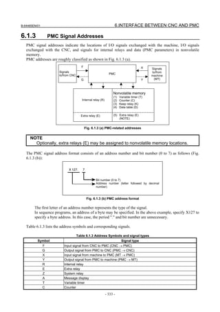

![B-64485EN/01 6.INTERFACE BETWEEN CNC AND PMC
M indicates an input signal from another PMC path.
N indicates an output signal to another PMC path.
(8) Other addresses
(a) Label number (L)
Sequence program instructions include an instruction to cause a jump to a specified position in
the middle of processing. This address indicates the jump destination used by this instruction.
The contents of L address can not be read/written in sequence program.
(b) Subprogram number (P)
In sequence programs, a main program can call subprograms. P addresses indicate the numbers
of these subprograms. The contents of P address can not be read/written in sequence program.
6.1.4 Communication Method for External I/O Device
For the high-speed serial interface, which passes input/output signals between the PMC and each I/O
device, there are two communication methods, i.e. the FANUC I/O Link i and the FANUC I/O Link.
You can use up to three channels for the serial interface. The communication method for channel 1 and
channel 2 can be specified by the CNC parameter. The default value “0” of the CNC parameter means
that I/O Link is specified. The channel 3 can be used only for I/O Link.
For the details of the setting of the CNC parameter, see PMC PROGRAMMING MANUAL
(B-64513EN).
CNC
I/O Link i
Channel 1 Select by CNC parameter
I/O Link
I/O Link i
Channel 2 Select by CNC parameter
I/O Link
Channel 3 I/O Link
Fig. 6.1.4(c) Setting of the communication method for each channels
The maximum I/O points of I/O Link i are 2048 poins/2048 points for each channel. The maximum I/O
points of I/O Link are 1024 points/1024 points for each channel. The maximum I/O points for a PMC
system are 4096 points/4096 points in total. You can use several channels of I/O Link i and I/O Link but
the total points cannot exceed the maximum points of the PMC system.
[The example of combination of I/O Link i and I/O Link]
Channel 1 Channel 2 Channel 3 Total points (DI / DO)
I/O Link i I/O Link i - 4096 / 4096
I/O Link i I/O Link I/O Link 4096 / 4096
I/O Link i I/O Link - 3072 / 3072
I/O Link I/O Link I/O Link 3072 / 3072
I/O Link i - - 2048 / 2048
I/O Link I/O Link - 2048 / 2048
I/O Link - I/O Link 2048 / 2048
I/O Link - - 1024 / 1024
- 335 -](https://image.slidesharecdn.com/b-64485en01-121129013453-phpapp02/85/B-64485-en-01-357-320.jpg)

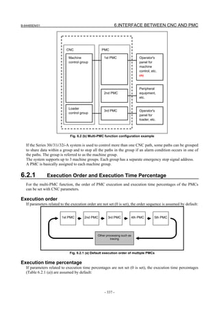


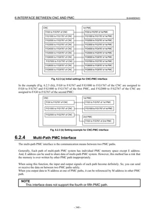
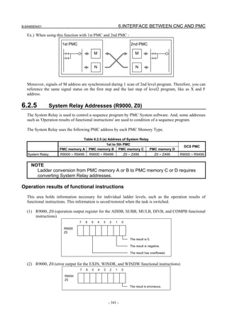

![B-64485EN/01 6.INTERFACE BETWEEN CNC AND PMC
7 6 5 4 3 2 1 0
R9015
Z15 "Ladder execution start signal"
(can be referenced only from the
ladder program)
"Ladder stop signal"
(can be referenced only from the
ladder program)
7 6 5 4 3 2 1 0
R9091
Z91
"1st Ladder execution status signal"
0: Ladder at a stop
1: Ladder being executed
"2nd Ladder execution status signal"
0: Ladder at a stop
1: Ladder being executed
"3rd Ladder execution status signal"
0: Ladder at a stop
1: Ladder being executed
Signal operation
Run
Ladder execution status
Stop
"Ladder execution start signal" 1
(R9015.0, Z15.0) 0
"Ladder stop signal" 1
(R9015.1, Z15.1) 0
"Ladder execution status signal" 1
(R9091.2, R9091.3, R9091.4, 0
Z91.2, Z91.3, Z91.4)
One ladder One ladder
scan cycle scan cycle
(1) Ladder execution start signal (R9015.0, Z15.0)
When directed to start ladder program execution, the system software starts executing the ladder
program, turns on this signal, and keeps it on for the first one scan cycle. Like R9000 or Z0, this
signal indicates the status of ladder execution corresponding to each ladder execution level. For this
reason, this signal is securely turned on for the first one scan cycle after the start of execution no
matter on what execution level the signal is referenced. This signal is turned on when:
(a) Ladder execution begins at power turn-on.
(b) The soft key [RUN] on the PMC screen is pressed.
(c) FANUC LADDER-III or a ladder editing package directs the ladder to start.
Referencing this signal in a ladder program can detect when ladder execution has begun, making it
possible to program preprocessing related to ladder execution.
- 343 -](https://image.slidesharecdn.com/b-64485en01-121129013453-phpapp02/85/B-64485-en-01-365-320.jpg)
![6.INTERFACE BETWEEN CNC AND PMC B-64485EN/01
CAUTION
Reference this signal only within a ladder program. Do not reference it from an
external system or program as it indicates the status of ladder execution
separately for each ladder execution level.
(2) Ladder stop signal (R9015.1, Z15.1)
When directed to stop ladder program execution, the system software turns off this signal and keeps
it off for the last one scan before stopping ladder program execution. Like R9000 or Z0, this signal
indicates the status of ladder execution corresponding to each ladder execution level. For this reason,
this signal is securely turned off for the last one scan before the stop of execution no matter on what
execution level the signal is referenced. This signal is turned off when:
(a) The soft key [STOP] on the PMC screen is pressed.
(b) FANUC LADDER-III or a ladder editing package directs the ladder to stop.
(c) On the PMC DATA I/O screen, the ladder program is loaded to the PMC.
(d) FANUC LADDER-III or a ladder editing package stores the ladder program to the PMC.
Referencing this signal in a ladder program can detect when ladder execution stops, making it
possible to program postprocessing related to ladder execution (that is, preprocessing for ladder
execution stop). Before the ladder is stopped, for example, it is possible to put signals in an proper
state for safety purposes.
CAUTION
1 Reference this signal only within the ladder program. Do not reference it from an
external system or program as it indicates the status of ladder execution
separately for each ladder execution level.
2 If the power is turned off or a CNC system alarm occurs, ladder execution and
I/O signal transfer are immediately stopped for safety purposes. In this case,
therefore, this signal cannot be used.
(3) Ladder execution status signal (R9091.2 to 4, R9093.0 to 1, Z91.2 to 4, Z93.0 to 1)
Referencing this signal from an external system or program, such as the network board, C Language
Executor program, FOCAS2 Ethernet, or HSSB library, can detect the execution status of the ladder
program.
(4) Example of using the signals
(a) Example of calling a subprogram just before the ladder stops
R9015.1
(Z15.1)
SUB65 Pxxxx
CALL
(b) Example of forcibly turning off an output signal programmed on the first ladder level just
before the ladder stops
R9015.1
Input (Z15.1) Output
- 344 -](https://image.slidesharecdn.com/b-64485en01-121129013453-phpapp02/85/B-64485-en-01-366-320.jpg)


![6.INTERFACE BETWEEN CNC AND PMC B-64485EN/01
6.4 OPERATING THE PMC SCREEN
The basic configuration of the PMC screen is described below.
Screen title Ladder PMC alarm PMC path NC program number
execution status
NC status indication [+]
Soft key page
turning key
Key entry line
Message display line
Return key
POS PROG OFFSET
SETTING
Function keys
SYSTEM MESSAGE GRAPH
• Screen title: Displays the name of a specific submenu of the PMC.
• Ladder execution status: Displays the execution status of the ladder program.
• PMC alarm: Indicates whether any PMC alarm is occurring.
• PMC path: Displays the currently selected PMC.
• NC program number: Displays the number of the currently selected NC program.
• Key entry line: Line for entering a numerical value or character key string.
• Message display line: Displays an error or warning message.
• NC status indication: Displays the NC mode, the execution status of the NC program, the
currently selected NC path number.
• Return key: Used to switch from the PMC operation menu to a specific PMC
submenu or from a specific PMC submenu to the main menu of the
PMC.
• Soft key page turning key: Used to turn soft key pages.
About the PMC screen
When you click the "SYSTEM" function key and then turn the soft key page by clicking the soft key [+],
the main menu of the PMC is displayed.
The PMC main menu offers the following three types of submenus, which are respectively used for
specific purposes.
• PMC maintenance
- 352 -](https://image.slidesharecdn.com/b-64485en01-121129013453-phpapp02/85/B-64485-en-01-374-320.jpg)


![B-64485EN/01 6.INTERFACE BETWEEN CNC AND PMC
6.5 PMC DIAGNOSIS AND MAINTENANCE SCREENS ([PMC
MAINTE])
6.5.1 Monitoring PMC Signal Status ([STATUS] Screen)
The SIGNAL STATUS screen displays the data at all addresses specified in the program. The data of
each address consists of a bit pattern (0s and/or 1s) and a hexadecimal or decimal number at the rightmost
position on a byte-by-byte basis.
Signal status display area
Additional information line
Fig. 6.5.1 (a) Signal status screen
The additional information line at the bottom of the screen displays the symbol and comment of the
address on which the cursor is placed. When the cursor is placed on a byte, the byte symbol and comment
are displayed.
Address Symbol Comment
Table contents
• ADDRESS: Address referenced by a sequence program
• 0 to 7: Data at each bit position
• HEX: Display of each byte in hexadecimal
• DEC: Display of each byte in decimal
Operation procedure
(1) Press the soft key [STATUS]. The screen shown above appears.
(2) Key in an address whose data to be displayed, then press the soft key [SEARCH].
(3) The data starting at the input address is displayed as a bit pattern.
(4) To display the data at another address, press the cursor keys, page keys, or soft key [SEARCH].
(5) To modify the status of a signal, switch to the forced I/O screen by pressing the soft key [FORCE].
- 355 -](https://image.slidesharecdn.com/b-64485en01-121129013453-phpapp02/85/B-64485-en-01-377-320.jpg)
![6.INTERFACE BETWEEN CNC AND PMC B-64485EN/01
NOTE
The soft key [FORCE] is displayed and usable when the forced I/O function is
enabled. For details, see PMC PROGRAMMING MANUAL (B-64513EN).
(6) On the forced I/O screen, an overridden X signal or Y signal is prefixed by a greater-than sign (>) to
indicate the setting of override.
Soft keys on the Signal Status screen
Address search Switching to the forced I/O screen PMC path switching
Switching to display in decimal
Switching to display in hexadecimal
Fig. 6.5.1 (b) Soft keys on the SIGNAL STATUS screen
6.5.2 Checking PMC Alarms ([PMC ALARM] Screen)
On this screen, an alarm message output from the PMC is displayed. To move to the PMC alarm screen,
press the soft key [PMC ALARM].
Page display
Alarm message display area
Fig. 6.5.2 (a) PMC alarm screen
In the alarm message display area, an alarm message output from the PMC is displayed. When many
alarm messages are output to two or more pages, the page keys can be used to switch from one page to
another.
- 356 -](https://image.slidesharecdn.com/b-64485en01-121129013453-phpapp02/85/B-64485-en-01-378-320.jpg)
![B-64485EN/01 6.INTERFACE BETWEEN CNC AND PMC
In the page display area to the right of the title, the number of the page currently displaying messages is
indicated.
For information about messages displayed, see Appendix A “Alarm List.”
6.5.3 Setting and Displaying Variable Timers ([TIMER] Screen)
This screen is used to set and display timer values for functional instruction variable timers (TMR:SUB 3).
This screen can be used in one of two modes: the simple display mode and the comment display mode.
To move to the TIMER screen, press the soft key [TIMER].
Page display
Key input line
Message
display line
Additional information
line
Fig. 6.5.3 (a) Time screen: simple display mode
Comment display
area
Fig. 6.5.3 (b) Time screen: comment display mode
Table contents
• NO.: Timer number specified for a functional instruction timer.
• ADDRESS: Address referenced by a sequence program
- 357 -](https://image.slidesharecdn.com/b-64485en01-121129013453-phpapp02/85/B-64485-en-01-379-320.jpg)

![B-64485EN/01 6.INTERFACE BETWEEN CNC AND PMC
6.5.4 Setting and Displaying Counter Values ([COUNTR] Screen)
This screen is used to set and display the maximum and current counter values for functional instruction
counters (CTR: SUB 5). This screen can be used in one of two modes: the simple display mode and the
comment display mode. To move to the COUNTER screen, press the soft key [COUNTR].
Page display
Key input line Message display line
Additional information line
Fig. 6.5.4 (a) Counter screen: simple display mode
Comment display
area
Fig. 6.5.4 (b) Counter screen: comment display mode
Table contents
• NO.: Counter number specified for a functional instruction counter
• ADDRESS: Address referenced by a sequence program
• PRESET: Maximum counter value (a minimum counter value is specified by a counter
instruction)
• CURRENT: Current counter value
• COMMENT: Comment on the C address of a setting value
- 359 -](https://image.slidesharecdn.com/b-64485en01-121129013453-phpapp02/85/B-64485-en-01-381-320.jpg)
![6.INTERFACE BETWEEN CNC AND PMC B-64485EN/01
The additional information line at the bottom of the screen displays the symbol and comment of the
address on which the cursor is placed. If the cursor is placed on a PRESET value, the symbol and
comment of the address of the PRESET value are displayed. If the cursor is placed on a CURRENT value,
the symbol and comment of the address of the CURRENT value are displayed.
Counter types and maximum values
Counter type PRESET maximum value CURRENT maximum value
BINARY 32767 32767
BCD 9999 9999
Soft keys on the COUNTER screen
Display mode switching C address search
6.5.5 Setting and Displaying Keep Relays ([KEEP RELAY] Screen)
This screen is used for setting and displaying the Keep Relays. To move to the KEEP RELAY screen,
press the [KEEP RELAY] soft key.
Page display
Key input line Message display line
Additional information line
Fig. 6.5.5 (a) Keep relay screen
Contents of the table
• ADDRESS: Address referred by sequence Program
• 0 to 7: Contents of each bit
• HEX: Value of the byte data in hexadecimal notation
The additional information line at the bottom of the screen displays the symbol and comment of the
address on which the cursor is placed. When the cursor is placed on a byte, the byte symbol and comment
are displayed.
Since Keep Relay is nonvolatile memory, the contents are not lost even if you turn off the power.
The Keep Relay area consists of parts as follows.
- 360 -](https://image.slidesharecdn.com/b-64485en01-121129013453-phpapp02/85/B-64485-en-01-382-320.jpg)
![B-64485EN/01 6.INTERFACE BETWEEN CNC AND PMC
30i/31i/32i-B
PMC memory PMC memory PMC memory PMC memory Dual check safety
Type A Type B Type C Type D PMC (option)
User area K0~K19 K0~K99 K0~K199 K0~K299 K0~K19
Area for management
K900~K999 K900~K999 K900~K999 K900~K999 K900~K999
software
CAUTION
If the area for the PMC management software is protected by the programmer
protection function, the area is not displayed on the KEEP RELAY screen. For
details, see PMC PROGRAMMING MANUAL (B-64513EN).
6.5.6 Setting and Displaying Data Tables ([DATA] Screen)
There are two data table types (data table control data table and data table). To move to the data screen,
press the soft key [DATA].
(1) DATA TABLE CONTROL screen ([LIST] screen)
Pressing the soft key [DATA] displays the DATA TABLE CONTROL screen for data table
management. This screen can be used in one of two modes: the simple display mode and the
comment display mode.
Display of the
number of groups
Page display
Key input line
Message display line
Additional information line
Fig. 6.5.6 (a) Data table control data screen: simple display mode
- 361 -](https://image.slidesharecdn.com/b-64485en01-121129013453-phpapp02/85/B-64485-en-01-383-320.jpg)
![6.INTERFACE BETWEEN CNC AND PMC B-64485EN/01
Comment
display area
Fig. 6.5.6 (b) Data table control data screen: comment display mode
Table contents
• GROUP TABLE COUNT: Number of data items in the data table
• NO.: Group number
• ADDRESS: Data table start address
• PARAMETER: Data table control parameter
• TYPE: Data length (0 = 1 byte, 1 = 2 bytes, 2 = 4 bytes, 3 = bit)
• DATA: Number of data items in each data table
• COMMENT: Comment on the start D address of each group
The additional information line at the bottom of the screen displays the symbol and comment of the
address on which the cursor is placed. When the cursor is placed on the PARAMETER, TYPE, or DATA
column, the current setting is displayed.
The ADDRESS column displays the start address of a data table. Multiple groups may share an address.
When the soft key [SYMBOL] is pressed, the symbol of the start address is displayed.
NOTE
The data table control parameters have the following meanings:
#7 #6 #5 #4 #3 #2 #1 #0
0: Binary format
1: BCD format (Bits 2 and 3 are invalid.)
0: Without input protection
1: With input protection
0: Binary or BCD format (Bit 0 is valid.)
1: Hexadecimal format (Bits 0 and 3 are invalid.)
0: Signed (valid only when bits 0 and 2 are set to 0)
1: Unsigned (valid only when bits 0 and 2 are set to 0)
- 362 -](https://image.slidesharecdn.com/b-64485en01-121129013453-phpapp02/85/B-64485-en-01-384-320.jpg)
![B-64485EN/01 6.INTERFACE BETWEEN CNC AND PMC
NOTE
1 When data table control data is protected by the programmer protection function,
the data table control data screen is not displayed. For details, see PMC
PROGRAMMING MANUAL (B-64513EN).
2 When PMC parameters are output using the I/O screen (see Subsection 7.5.7,
“Data Input/Output ([I/O] Screen)”), only the data of an address D area set in the
data table control data is output from the data table screen. The data of an
address D area not set in the data table control data is not output.
Soft keys on the DATA TABLE CONTROL screen
Switching to the soft keys for
PMC path switching
data size setting
Display mode switching
Switching to Extra
Switching to the zoom screen Symbol display switching relay screen
Input of the number of groups Switching to the
soft keys for
Group number search parameter setting
Data table control data Switching to Data
Address display switching
initialization table screen
Soft keys for parameter setting
Setting for signed decimal Setting for hexadecimal
Setting for unsigned Setting for BCD Protection state modification
decimal
Soft keys for data size setting
Setting for byte Setting for bit
Setting for word Setting for double word
- 363 -](https://image.slidesharecdn.com/b-64485en01-121129013453-phpapp02/85/B-64485-en-01-385-320.jpg)
![6.INTERFACE BETWEEN CNC AND PMC B-64485EN/01
(2) DATA TABLE screen ([ZOOM] screen)
If the data table control data is specified, clicking the soft key [ZOOM] on the data table control data
screen displays the data table setting screen. This screen can be used in one of three modes: the
simple display mode, the comment display mode, and the bit display mode.
Group
information line
Page display
Key input line Message display line
Additional information line
Fig. 6.5.6 (c) Data table screen: simple display mode
Comment display area
Fig. 6.5.6 (d) Data table screen: comment display mode
- 364 -](https://image.slidesharecdn.com/b-64485en01-121129013453-phpapp02/85/B-64485-en-01-386-320.jpg)

![6.INTERFACE BETWEEN CNC AND PMC B-64485EN/01
EXTRA RELAY CONTROL screen ([LIST] screen)
To switch to the EXTRA RELAY CONTROL screen in which you can manage the extra relay tables, use
[EXTRA RELAY] soft key in DATA TABLE CONTROL screen.
The operation of this screen is similar to the DATA TABLE CONTROL screen. See “DATA TABLE
CONTROL screen ([LIST] screen)” for the detail of the operations.
To make it easy to distinguish the EXTRA RELAY CONTROL screen from DATA TABLE CONTROL
screen, the EXTRA RELAY CONTROL screen has white background at the line of “GROUP TABLE
COUNT”.
Fig. 6.5.6 (f) EXTRA RELAY CONTROL screen: simple display mode
- 366 -](https://image.slidesharecdn.com/b-64485en01-121129013453-phpapp02/85/B-64485-en-01-388-320.jpg)
![B-64485EN/01 6.INTERFACE BETWEEN CNC AND PMC
EXTRA RELAY screen ([ZOOM] screen)
When the extra relay control data are properly set, pressing [ZOOM] soft key at EXTRA RELAY
CONTROL screen leads you to the EXTRA RELAY screen. Similarly to the DATA TABLE screen,
this screen can show the contents of extra relays in three display modes; the simple display mode, the
comment display mode, and the bit display mode.
The operation of this screen is similar to the DATA TABLE screen. See “DATA TABLE screen
([ZOOM] screen)” for the detail of the operations.
To make it easy to distinguish the EXTRA RELAY screen from DATA TABLE screen, the
EXTRARELAY screen has white background at the line of the group information.
Fig. 6.5.6 (g) EXTRA RELAY screen: simple display mode
6.5.7 Data Input/Output ([I/O] Screen)
To move to the I/O screen, press the soft key [I/O].
Fig. 6.5.7 (a) I/O screen
- 367 -](https://image.slidesharecdn.com/b-64485en01-121129013453-phpapp02/85/B-64485-en-01-389-320.jpg)


![6.INTERFACE BETWEEN CNC AND PMC B-64485EN/01
6.5.8 Displaying i/o devices connection status ([I/O DEVICE]
screen)
I/O DEVICE MONITOR screen shows the types and the ID codes of I/O Units that are connected to I/O
Link in order of Group number.
If the number of groups assigned in the I/O module assignment data does not match the number of
actually connected groups, the difference is displayed on the screen.
When the I/O device configuration is registered in this screen, the difference between the registered
groups and actually connected groups is displayed.
To switch the screen display to the I/O DEVICE MONITOR screen, press the [I/O DEVICE] soft key.
The screen supports the following operations.
• Registration of I/O device configuration [REG.]
• Deletion of I/O device configuration [DELETE]
NOTE
The [REG.] and [DELETE] operations are performed for each channel
separately.
Channel number
Registered date
Difference mark
I/O Unit type
Group number
I/O Unit ID code
図6.5.8 (a) I/O device screen
Table 6.5.8(a) Displayed type and actual type of I/O Units (for I/O Link)
Displayed I/O Unit ID Actual I/O Unit
CONNECTION UNIT 80 Connection Unit
OPERATOR PANEL 82 Connection Unit for Operators Panel
I/O-B3 83 I/O B3
IO UNIT-MODEL A 84 I/O Unit-MODEL A
86
87
POWER MATE / I/O LINK BETA 4A Power Mate or I/O Link Beta
SERIES 0 50 Series 0
OPERATOR I/F BOARD (MPG1) 53 Machine Operators Panel Interface
- 370 -](https://image.slidesharecdn.com/b-64485en01-121129013453-phpapp02/85/B-64485-en-01-392-320.jpg)
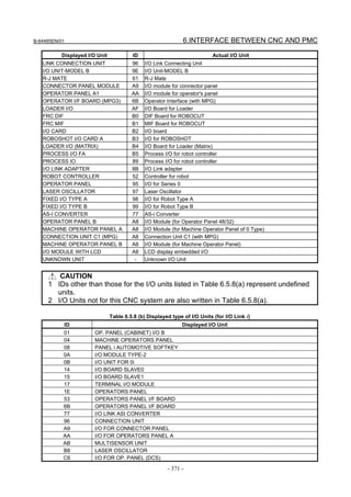
![6.INTERFACE BETWEEN CNC AND PMC B-64485EN/01
ID Displayed I/O Unit
C7 I/O FOR OP. PANEL (DCS)_S
C8 SAFETY IO UNIT
D0 I/O UNIT-MODEL A
D8 I/O UNIT-MODEL B
D9 HANDY MACHINE OP. PANEL
Soft keys
Displays connection status of Deletes I/O devices
the next channel configuration
Displays connection status of Registers I/O devices
the previous channel configuration
6.5.9 Signal Trace Function ([TRACE] Screen)
Fig. 6.5.9 (a) Signal trace screen (initial screen)
Before trace operation can be executed, the trace parameters must be set. Press the soft key [TRACE
SETING] to switch the screen display to the trace parameter setting screen.
By setting the PMC setting screen, the trace function can be automatically started after the power is
turned on. In this case as well, the trace parameters must be set beforehand.
NOTE
For the setting to automatically start the trace function after the power is turned
on, see Subsection 7.5.11.2.
- 372 -](https://image.slidesharecdn.com/b-64485en01-121129013453-phpapp02/85/B-64485-en-01-394-320.jpg)
![B-64485EN/01 6.INTERFACE BETWEEN CNC AND PMC
6.5.10 Setting of Trace Parameter ([TRACE SETING] Screen)
On the trace parameter setting screen, a sampling condition can be set. The screen consists of two pages.
Use the page keys to switch between the pages.
Fig. 6.5.10 (a) Trace parameter setting screen (first page)
(a) SAMPLING/ MODE
Determines the sampling mode.
• TIME CYCLE: Samples at every specified cycle time.
• SIGNAL TRANSITION: Monitors the signal at a set cycle and samples when the signal
makes a transition.
(b) SAMPLING/ RESOLUTION
The resolution of sampling is inputted. The default value is the minimum sampling resolution (msec),
which varies depending on the CNC.
Setting range: Minimum sampling resolution to 1000 (msec)
An input value is rounded off to a multiple of the minimum sampling resolution (msec) which is
closest to but not greater than the input value.
(c) SAMPLING/ TIME
This parameter is displayed when "TIME CYCLE" is set on "SAMPLING/ MODE". The execution
time of trace is inputted. The value of "SAMPLING/ RESOLUTION" or the number of specified
signal address changes the range of the value that is able to input. The range is displayed on the right
side.
(d) SAMPLING/ FRAME
This parameter is displayed when "SIGNAL TRANSITION" is set on SAMPLING/ MODE". The
number of sampling is inputted. The value of "SAMPLING/ RESOLUTION" or the number of
specified signal addresses changes the range of the value that is able to input. The range is displayed
on the right side.
(e) STOP CONDITION
Determines the condition to stop the trace.
• NONE: Does not stop the tracing automatically.
• BUFFER FULL: Stops the tracing when the buffer becomes full.
• TRIGGER: Stops the tracing by trigger.
(f) STOP CONDITION/ TRIGGER/ ADDRESS
When "TRIGGER" is set on "STOP CONDITION", this parameter is enabled. Input signal address
or symbol name as stop trigger.
A PMC number can be set for a trigger address by entering the PMC number at the time of address
setting.
- 373 -](https://image.slidesharecdn.com/b-64485en01-121129013453-phpapp02/85/B-64485-en-01-395-320.jpg)


![6.INTERFACE BETWEEN CNC AND PMC B-64485EN/01
b) Soft keys
Soft keys on the setting screen of sampling address are as follows
• DELETE : Clears the value of the edit box on the cursor.
• SYMBOL/ADDRESS : Changes the address display to the symbol display. However, display
of the address that is not defined the symbol does not change. This
soft key also changes to "ADDRESS". The following soft keys are
displayed.
• MOVE UP : Exchanges the signal indicated the cursor for the signal above one line.
• MOVE DOWN : Exchanges the signal indicated the cursor for the signal below one line.
• DELETE ALL : Clears all of the value of the edit box.
• READ : Reads the trace setting files.
• I/O DEVICE : Selects input device of the trace setting file and output device of the trace
result data. Pressing the soft-key switches “memory card” or “USB
memory” alternately.
c) Trigger setting
When "SIGNAL TRANSITION" is set on "TRACE MODE" and "ANY CHANGE" is set on
"SAMPLING CONDITION", it can be set whether to use the setting address as the signals that
should trigger the sampling in the setting signals. As for the signal address where the trigger was set,
" " is displayed right. Soft keys on the Trigger setting screen are as follows:
• TRGON: Sets the Trigger on.
• TRGOFF:Sets the Trigger off.
The default setting is trigger on for all signals.
6.5.11 Execution of Trace
After the trace parameters are set, a trace operation can be started by pressing the soft key [(OPRT)] and
the soft key [RUN] on the SIGNAL TRACE screen. The following is the screen examples of the trace
execution by "TIME CYCLE" mode and "SIGNAL TRANSITION" mode.
Fig. 6.5.11 (a) Trace execution screen (TIME CYCLE mode)
- 376 -](https://image.slidesharecdn.com/b-64485en01-121129013453-phpapp02/85/B-64485-en-01-398-320.jpg)
![B-64485EN/01 6.INTERFACE BETWEEN CNC AND PMC
Fig. 6.5.11 (b) ) Trace execution screen (SIGNAL TRANSITION mode)
The result of trace is immediately displayed during execution of the trace.
When the stop conditions that is set in parameter setting screen is satisfied the execution is finished.
Pushing soft key [STOP] aborts the execution. In "SIGNAL TRANSITION" mode, graphic display is not
refreshed until any signal for sampling trigger changes.
6.5.11.1 Operation after execution of trace
When the execution is finished, the result of trace is displayed. The Fig. 6.5.11.1 (a) and Fig. 6.5.11.1 (b)
are the screen examples of trace by "TIME CYCLE" and "SIGNAL TRANSITION" mode.
Fig. 6.5.11.1 (a) Trace result screen (TIME CYCLE mode)
- 377 -](https://image.slidesharecdn.com/b-64485en01-121129013453-phpapp02/85/B-64485-en-01-399-320.jpg)
![6.INTERFACE BETWEEN CNC AND PMC B-64485EN/01
Fig. 6.5.11.1 (b) Trace result screen (SIGNAL TRANSITION mode)
The cursor indicating current position is initially displayed on the original point (0 point). The position of
the cursor is displayed in "CURSOR POSITION" in the upper of the screen. The cursor can move
horizontally with the <←> or <→> key. After the execution, following operation is enabled.
a) Scroll of screen
• Cursor up/down key and Page up/down key
Enables the vertical scroll for the specified signal
• Cursor right/left key, soft key [NEXT>>] and soft key [<< PREV]
Enables the horizontal scroll of the graph.
b) Automatic calculation of the selected range
Pushing soft key [MARK] marks the current position and displays the mark cursor.
If the mark cursor duplicates with the current position cursor, the current position cursor has priority
of display. The "MARK POSITION" that shows the position of the mark cursor and "RANGE" that
shows the range between the mark cursor and the current position cursor are displayed in the upper
of screen.
Moving the current position cursor changes these values. Pushing soft key [MARK] again releases
the select range mode.
- 378 -](https://image.slidesharecdn.com/b-64485en01-121129013453-phpapp02/85/B-64485-en-01-400-320.jpg)
![B-64485EN/01 6.INTERFACE BETWEEN CNC AND PMC
Fig. 6.5.11.1 (c) Trace result screen (Mark cursor display)
c) Zoom in/Zoom out of waveform
Pushing soft key [ZOOM IN] magnifies the display of chart. Pushing soft key [ZOOM OUT]
reduces the display of chart. Pushing these soft keys also change the scale value of the graduation on
the graph. When trace is just finished, the default zooming level was the most magnified level. In
[ZOOM OUT] mode, "X" is displayed as following screen example when the transitions of signal
cannot be expressed accurately enough. The limitation of [ZOOM OUT] displays all of result of the
trace in one page.
Fig. 6.5.11.1 (d) Trace result screen (Zoom out display)
d) Exchange of sampling signal
Pushing soft key [MOVE UP] exchanges the signal indicated by the signal cursor for the signal one
line above. Pushing soft key [MOVE DOWN] exchanges the signal indicated by the signal cursor
for the signal one line below. The result of the operation is cancelled by the execution of trace or
putting the power off. When you would like to preserve the order of displayed signals against the
executing or powering off, please change the order on "SAMPLING ADDRESS" screen.
- 379 -](https://image.slidesharecdn.com/b-64485en01-121129013453-phpapp02/85/B-64485-en-01-401-320.jpg)
![6.INTERFACE BETWEEN CNC AND PMC B-64485EN/01
e) Output of the trace result data
Pressing the [OUTPUT] soft key outputs the trace result data to “memory card” or “USB memory”.
6.5.11.2 Automatic start of trace setting
Trace execution is automatically started after power-on by setting a PMC setting data.
• TRACE START = MANUAL/AUTO
NOTE
For details of the method of setting PMC setting data, see PMC
PROGRAMMING MANUAL (B-64513EN).
6.5.12 MONITORING I/O DIAGNOSIS ([I/O DGN] SCREEN)
In I/O Diagnosis screen, you can check the status of each I/O variable. You can also check the
configuration of I/O devices and the communication status with them.
Listing order
Additional information
Fig. 6.5.12 (a) I/O diagnosis screen
GRP (GROUP)
To include a specific string which means a kind of signals in a part of symbol string, these signals on I/O
diagnosis screen are classified and you can easy to understand the status of signals.
The group names of the I/O variables are displayed, which are extracted (Max. 4 chars) out of their
symbol names as configured in “GROUP FORMAT” in the setting screen.
The groups to be displayed can be specified by soft key.
[ALL GROUPS] All groups are displayed.
[GROUP] The group entered by key or the group under the cursor is selected to be displayed.
PROG.SYMBOL (SYMBOL)
The symbol names of the I/O variables are displayed.
ADDRESS
The actual locations of I/O variables are displayed.
- 380 -](https://image.slidesharecdn.com/b-64485en01-121129013453-phpapp02/85/B-64485-en-01-402-320.jpg)


![6.INTERFACE BETWEEN CNC AND PMC B-64485EN/01
6.6 LADDER DIAGRAM MONITOR AND EDITOR SCREENS
([PMC LADDER])
The PMC LADDER menu contains the screens related to PMC Ladder diagrams, such as the program list
screen and the LADDER DIAGRAM MONITOR/EDITOR screens.
You can switch to the PMC LADDER menu by operating on the "SYSTEM" key and then the soft key
[PMC LADDER].
SYSTEM
PMC main menu
PMC LADDER menu
PMC LADDER LIST Program list screen
LADDER LADDER DIAGRAM
< MONITOR/EDITOR screen
DUP. CHECK Duplicate coil check screen
Fig. 6.6 (a) PMC LADDER menu
Clicking the soft key [LADDER] causes the sequence program to be dynamically displayed, allowing you
to monitor operation. The editor screen allows you to make changes to relay and functional instructions in
the sequence program to change the operation of the sequence program.
The ladder diagram display/editor functions consist of the following screens:
(1) LADDER DIAGRAM MONITOR screen
Displays ladder diagrams to monitor the current states of relays, coils, and so on.
(2) COLLECTIVE MONITOR screen
Displays only a selected ladder net to monitor the current states of relays, coils, and so on.
(3) LADDER DIAGRAM EDITOR screen
Allows you to edit a ladder diagram in units of nets.
(4) NET EDITOR screen
Allows you to edit a single net in a ladder diagram.
(5) PROGRAM LIST VIEWER screen
Allows you to select the subprogram to be displayed on the LADDER DIAGRAM MONITOR
screen.
(6) PROGRAM LIST EDITOR screen
Allows you to edit a ladder program in units of subprograms. Also allows you to select the
subprogram to be edited on the LADDER DIAGRAM EDITOR screen.
The following screens can be called from the LADDER DIAGRAM EDITOR screen:
(7) FUNCTIONAL INSTRUCTION DATA TABLE VIEWER screen
Allows you to view the contents of the data table for a data table attached functional instruction.
(8) FUNCTIONAL INSTRUCTION DATA TABLE EDITOR screen
Allows you to edit the contents of the data table for a data table attached functional instruction.
(9) SUBPROGRAM LIST VIEWER screen
Displays the list of the called subprogram and the subprogram switching history.
NOTE
You can protect these screens by using the programmer protection function. For
details, see PMC PROGRAMMING MANUAL (B-64513EN).
- 384 -](https://image.slidesharecdn.com/b-64485en01-121129013453-phpapp02/85/B-64485-en-01-406-320.jpg)
![B-64485EN/01 6.INTERFACE BETWEEN CNC AND PMC
You can move among screens as shown in the Fig. 6.6 (b).
Display Function
PMC main menu
(Monitor)
[<] [PMC LADDER]
PMC LADDER menu
[<] [<]
[BACK] [LADDER] [LIST] [DUP. CHECK] [<]
[SPLIST] [ZOOM]
SUBPROGRAM LIST LADDER DIAGRAM PROGRAM LIST Duplicate coil check
VIEWER screen MONITOR screen [LIST] VIEWER screen screen
[LADDER]
[ZOOM] [BACK] [JUMP]
[LIST] [ZOOM]
[BACK]
[LIST] [ZOOM]
[EXIT EDIT] [SWITCH]
[EDIT]
COLLECTIVE MONITOR screen
Edit Function [ZOOM]
LADDER DIAGRAM PROGRAM LIST
EDITOR screen EDITOR screen
[LIST]
[EXIT] [CREATE NET] [ZOOM]
NET EDITOR screen
Fig. 6.6 (b) Transition among screens
NOTE
The [EDIT] soft key on the LADDER DIAGRAM MONITOR screen is displayed
and becomes available if the programmer protection function enables to edit
ladder program. For details, see PMC PROGRAMMING MANUAL (B-64513EN).
6.6.1 Displaying a Program List ([LIST] Screen)
The PROGRAM LIST VIEWER screen shows program information such as the program size.
SP area
Size area
Ladder preview display area
Program number area
Key input line Message display line
Fig. 6.6.1 (a) Program list viewer screen
- 385 -](https://image.slidesharecdn.com/b-64485en01-121129013453-phpapp02/85/B-64485-en-01-407-320.jpg)
![6.INTERFACE BETWEEN CNC AND PMC B-64485EN/01
(1) Screen structures
(a) A program list is displayed on the left side of the screen; on the right side, the ladder diagram
of the program currently indicated by the cursor on the program list is displayed.
(b) In the message line, error messages or inquiry messages will be displayed depending on the
situation.
(c) The program list displays up to 18 programs at a time in the list display area.
(2) Area of program list
(a) In the "SP area", the protect information for subprograms is displayed, so are their program
types.
(Key): Ladder program, cannot be viewed, cannot be edited
(Magnifying glass): Ladder program, can be viewed, cannot be edited
(Pencil): Ladder program, can be viewed, can be edited
(b) Program name is displayed in the "PROG NO." field for each program.
There are three kinds of program names.
COLLECT: It means the collective program.
GLOBAL: It means the whole program.
LEVELn (n = 1, 2, 3): It means the Ladder level 1, 2 and 3.
Pm (m = subprogram number): It means subprogram.
By changing the "ADDRESS NOTATION" item on the LADDER DIAGRAM MONITOR
Setting screen to "SYMBOL", you can display symbols.
(c) The program size is displayed in the "SIZE" field for each program.
If the program size is not over 1024 byte, the unit is shown in byte.
If it is over 1024 byte, the unit is shown in kilo (1024) byte with "K".
Ex.) The case that program size is not over 1024 byte.
1023 bytes: "1023" is shown.
Ex.) The case that program size is over 1024 byte.
20000 bytes: "19K" is shown.
(Sizes are rounded off to whole numbers before being displayed.)
Soft key of PROGRAM LIST VIEWER screen
Search for program
Display the contents
of program
6.6.2 Monitoring Ladder Diagrams ([LADDER] Screen)
LADDER DIAGRAM MONITOR screen shows the on/off status of contacts and coils, and the contents
of address specified for parameter of functional instructions.
From the PMC LADDER menu, you can switch to the LADDER DIAGRAM MONITOR screen by using
the soft key [LADDER]. You can use following operation at this screen, including "Forced I/O function
(Forcing mode)", by which you can force the relay or the address parameters of functional instructions to
a new status or value.
• Switch subprogram to show [LIST]
• Search for address or others [SEARCH MENU]
• Show data table of functional instructions [DATA TABLE]
• Go to COLLECTIVE MONITOR Screen [SWITCH]
• Forced I/O function (Forcing mode) "number" + INPUT key
- 386 -](https://image.slidesharecdn.com/b-64485en01-121129013453-phpapp02/85/B-64485-en-01-408-320.jpg)

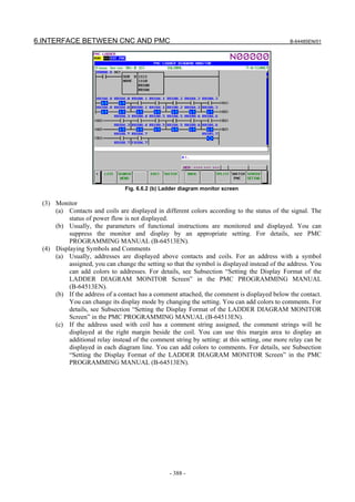
![B-64485EN/01 6.INTERFACE BETWEEN CNC AND PMC
Main soft keys of LADDER Diagram Monitor screen Switch PMC paths
LADDER Diagram Editor Switch to COLLECTIVE Screen Settings
Program List Display Subprogram
MONITOR screen
Back previous Subprogram List
Display Data Table
Exit
Search soft keys Search Write Coil Search previous Search next
Jump to Search Functional Pick up a Ladder
Top/Bottom Search Address or Net Instruction Diagram net Switch range
6.6.3 Editing Ladder Programs
At LADDER DIAGRAM EDITOR screen you can edit LADDER program to change its behavior.
To switch LADDER DIAGRAM EDITOR screen, press soft key [EDIT] at LADDER DIAGRAM
MONITOR screen.
Following operations are available at LADDER DIAGRAM EDITOR screen.
• Delete by net [DELETE]
• Move by net [CUT] & [PASTE]
• Copy by net [COPY] & [PASTE]
• Change address of contacts and coils "bit address" + INPUT key
• Change parameters of functional instructions "number" or "byte address" + INPUT key
• Add new net [CREATE NET]
• Change construction of net [ZOOM]
• Make changes effective [UPDATE]
• Abandon changes [RESTRE]
• Cancel edit [CANCEL EDIT]
- 389 -](https://image.slidesharecdn.com/b-64485en01-121129013453-phpapp02/85/B-64485-en-01-411-320.jpg)
![6.INTERFACE BETWEEN CNC AND PMC B-64485EN/01
Fig. 6.6.3 (a) Ladder diagram editor screen
CAUTION
1 You can edit ladder programs regardless of whether they are active or not. To
execute a ladder program with the results of editing being reflected, you must
update the ladder program. To do this, click the soft key [UPDATE], or update the
program when exiting from the LADDER DIAGRAM EDITOR screen. For details
of the method of protecting editing, see “PMC PROGRAMMING MANUAL
(B-64513EN).”
2 After you have edited a sequence program, the results of editing will be lost if the
power is turned off without first writing the edited sequence program to flash
ROM.
Write the sequence program to flash ROM on the I/O screen. If you set "WRITE
TO F-ROM(EDIT)" to "YES" on the general functions' setting parameter screen, a
confirmation message will be displayed, prompting you to ask whether to write a
sequence program to flash ROM after the end of editing. For details of this
setting, see “PMC PROGRAMMING MANUAL (B-64513EN).”
(1) Screen structures
(a) It is basically same with LADDER DIAGRAM MONITOR screen, except that no monitor
displays of relays and parameters of functional instructions are displayed.
(b) At right side of LADDER Diagram area, a position bar is always displayed, which indicates
screen position within current subprogram: in LADDER DIAGRAM MONITOR screen, this
position bar is exclusively displayed with comments of write coil. Sometimes, this position bar
hides a part of write coil comments.
(2) LADDER Diagram
(a) Style of LADDER Diagram is basically same with LADDER DIAGRAM MONITOR screen,
except that functional instructions are drawn always in "COMPACT" format that has no
monitor displays.
(b) Cursor is shown always. And the net, which will be an object of following editing operations, is
emphasized in screen.
- 390 -](https://image.slidesharecdn.com/b-64485en01-121129013453-phpapp02/85/B-64485-en-01-412-320.jpg)
![B-64485EN/01 6.INTERFACE BETWEEN CNC AND PMC
Soft keys of LADDER Diagram Editor screen
Program List
Change to Search soft keys Select net Copy net
Edit new net Delete net Cut net Paste net
Automatic input
Add net
Make changes
effective Exit
Change address Setting screen Cancel edit
Abandon changes Run/stop LADDER
Display address
map display
screen
WARNING
You have to pay special attention to modify running LADDER program. If you
modify LADDER program in wrong way, or update LADDER program with the
machine in improper status, it may cause unexpected reaction of the machine.
You have to make it sure that modifications you make on LADDER program is
appropriate, machine is in proper status, and nobody is near the machine, when
you update LADDER program.
6.6.3.1 NET EDITOR screen
At NET EDITOR screen, you can create new net, and modify existing net.
• Changing existing nets
If you move a net with the soft key [ZOOM], you will enter a mode (Modify mode) in which you
can add changes to the net currently indicated by the cursor.
• Adding a new net
When soft key [CREATE NET] is used, this screen is in "New mode" to create new net from
nothing.
Following operations are available at this screen:
• Place new contacts and coils "bit address" + [ ], [ ], etc.
• Change type of contacts and coils [ ], [ ], etc.
• Place new functional instructions [FUNC]
• Change type of functional instructions [FUNC]
• Erase contacts, coils, and functional instructions [ ]
• Draw/erase connecting lines [ ], [ ], [ ]
• Edit data table of functional instructions [DATA TABLE]
• Insert line/column [INSERT LINE], [INSERT COLUMN], [APPEND COLUMN]
•](https://image.slidesharecdn.com/b-64485en01-121129013453-phpapp02/85/B-64485-en-01-413-320.jpg)