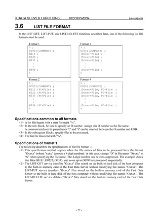
This manual provides instructions for setting up and using communication functions on FANUC CNC such as the Series 30i/31i/32i/35i. It includes specifications for the embedded Ethernet and optional board, as well as software and hardware options. The document covers data server functions, FOCAS2/Ethernet functions, DNS/DHCP client functions, machine remote diagnosis functions, unsolicited messaging functions, and FTP file transfer functions. It provides details on setting up and operating each of these functions, as well as related NC parameters and examples of common configurations. Safety precautions are also outlined.


![2.ABOUT USE WITH Series
B-64014EN/04 SPECIFICATION 30i/31i/32i/35i-B
2 ABOUT USE WITH Series 30i/31i/32i/35i-B
The hardware of Series 30i/31i/32i/35i-B is different from one of Series 30i/31i/32i-A.
In this section, the difference of the specification is described.
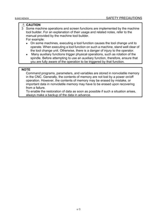
2.1 HARDWARE OPTIONS
In Series 30i/31i/32i/35i-B, the following hardware is prepared for Fast Ethernet.
Kind of hardware Description
Fast Ethernet circuit mounted on the main board of the LCD-mounted type Series
Multi-function Ethernet
30i/31i/32i/35i-B (Connector name: CD38B)
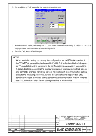
Fast Ethernet board Option board mounted in the optional slot (Connector name: CD38R)
The above hardware can be used as hardware for the FL-net according to the setting of the NC parameters
(No.970-972).
The information when the hardware is used as hardware for Fast Ethernet is described in this manual.
Refer to “FL-net Board CONNECTION MANUAL” (B-64163EN) regarding the FL-net function.
2.2 SOFTWARE OPTIONS
In Series 30i/31i/32i/35i-B, the following software functions can be used by the hardware options shown
in section 2.1.
Function name Drawing Description
Ethernet function A02B-xxxx-S707 Ethernet function (ex. FOCAS2/Ethernet) can be used.
Data Server function A02B-xxxx-S737 Data Server function can be used. (NOTE1)
FL-net function A02B-xxxx-J692 FL-net function can be used.
FL-net PORT2 function A02B-xxxx-R964 Two FL-net functions can be used simultaneously.
NOTE
1 The Data Server function cannot be used on Multi-function Ethernet.
The Data Server function cannot be used on the Series 35i-B.
2 In the Series 30i/31i/32i-A, the special software and software options are
necessary to use the FL-net/Ethernet coexisting function. But, in the Series
30i/31i/32i/35i-B, it is possible to use FL-net/Ethernet coexisting function by only
Ethernet function and FL-net function.
Please refer to “2.3 RELATED NC PARAMETERS” about the setting for
FL-net/Ethernet coexisting function.
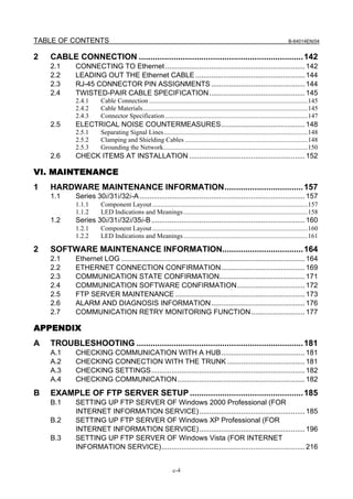
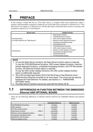
2.3 RELATED NC PARAMETERS
0970 Select hardware that operates Ethernet or Data Server function
0971 Select hardware that operates first FL-net function
0972 Select hardware that operates second FL-net function
[Input type] Parameter input
[Data type] Byte
[Valid data range] -1 to 6
Hardware that operates each function is selected. Please refer to the next section, too.
-9-](https://image.slidesharecdn.com/b-64014en04-121129012902-phpapp02/85/B-64014-en-04-21-320.jpg)
![2. ABOUT USE WITH Series
30i/31i/32i/35i-B SPECIFICATION B-64014EN/04
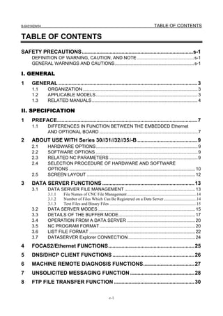
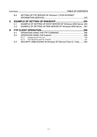
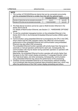
Required hardware Required software option NC parameters
Fast Ethernet board (slot1) J692 No.971 = 3
case 4 Two Ethernets
Fast Ethernet board (slot2) R964 No.972 = 4
case 5 One Ethernet Fast Ethernet board (slot1) S737 (+S707) No.970 = 3
No.970 = 3
case 6 One Ethernet Fast Ethernet board (slot1) S707 + J692
No.971 = 3
case 7 One Ethernet Fast Ethernet board (slot1) S707 No.970 = 3
case 8 One Ethernet Fast Ethernet board (slot1) J692 No.971 = 3
NOTE
1 When the Data Server function is selected, whether the Ethernet function is
selected does not affect the subsequent selection procedure because the
Ethernet and Data Server functions always operate on the same hardware.
2 It is not selectable because only two option boards can be mounted in the
stand-alone type of Series 35i-B.
2.5 SCREEN LAYOUT
In this manual, each screen has described the example of the screen of Series 30i/31i/32i-A. A basic
content is the same though a detailed layout might be different.
The hardware can be confirmed in title part of each screen of Series 30i/31i/32i/35i-B.
The kind of the hardware is shown on the title bar as the above example like [MULTI –FUNC ETHER].
Title Description
Fast Ethernet circuit mounted on the main board of the LCD-mounted type Series
[MUTI-FUNC ETHER]
30i/31i/32i/35i-B
[BOARD(SLOT1)] Option board mounted in the optional slot 1
[BOARD(SLOT2)] Option board mounted in the optional slot 2
[BOARD(SLOT3)] Option board mounted in the optional slot 3
[BOARD(SLOT4)] Option board mounted in the optional slot 4
- 12 -](https://image.slidesharecdn.com/b-64014en04-121129012902-phpapp02/85/B-64014-en-04-24-320.jpg)
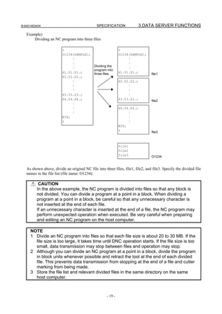
![B-64014EN/04 SPECIFICATION 3.DATA SERVER FUNCTIONS
For details, see Section 2.2, "RELATED NC PARAMETERS," in Part III, "SETTING."
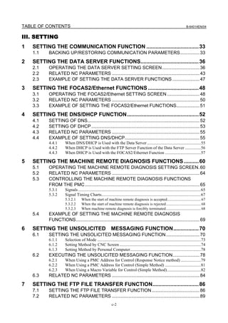
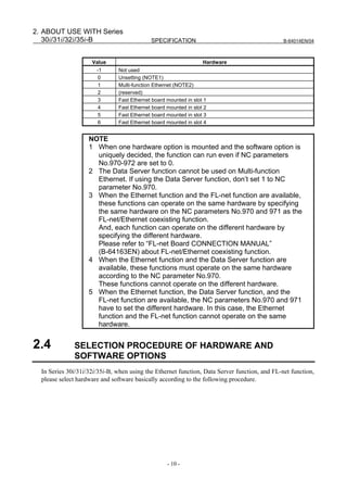
3.1.3 Text Files and Binary Files
You can store the following two types of files on a memory card on a Data Server: text files and binary
files.
For a text file, memory operation and edit operation as well as DNC operation can be performed by
selecting it as a main program.
For binary files, only DNC operation is available, but binary input operation in the high-speed remote
buffer A format is available.
If NC data other than an NC program is not handled as a binary file, it may not be able to be input or
output correctly. NC data output and stored on a memory card on a Data Server from the CNC is
automatically handled as a binary file. A file to be transferred from a personal computer to a memory card
on a Data Server must be specified explicitly as a binary file.
More specifically, for GET operation on a Data Server operation screen, you can use soft key [GET] or
[BGET] to specify whether to handle the file as a text file or a binary file.
When the Data Server is used as an FTP server, you can execute an ASCII (text file) command or a BIN
(binary file) command on your personal computer (FTP client) to specify whether to handle the file as a
text file or a binary file.
NOTE
1 An NC program stored as a text file is converted to an editable file format so that
the file can be edited on the CNC. For this reason, when a text file is read from
the host computer to the memory card on the Data Server, then the file is
transferred to the host computer, binary compatibility can no longer be
maintained.
2 The file name of a text file and the O number or arbitrary file name in the
program are always the same. See Section 3.5, “NC PROGRAM FORMAT” for
details
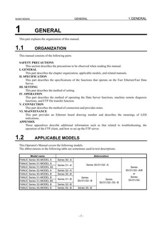
3.2 DATA SERVER MODES
Each Data Server mode determines the input or output destination when a Data Server is operated as a
CNC external input/output device. You can select one of the following three modes.
NOTE
Data Server modes are valid only when the Data Server is operated as an
external storage device of the CNC. In case of main program operation for
editing and a memory operation and an M98-based subprogram call, programs
on the memory card of the Data Server are selected regardless of the Data
Server mode.
Storage mode
The memory card built into the Data Server is selected as the external input/output device.
For example, when DNC operation or M198-based subprogram calling is executed, the relevant NC
program is called from the memory card built into the Data Server.
When input operation is executed for the Data Server, the relevant NC program is read from the memory
card built into the Data Server.
Conversely, when NC program output operation is executed for the Data Server, the output NC program
is written on the memory card built into the Data Server.
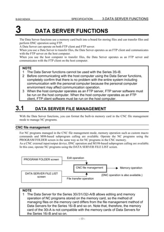
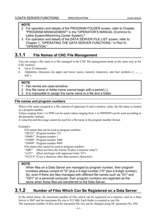
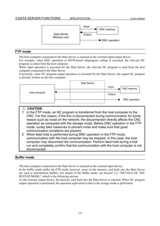
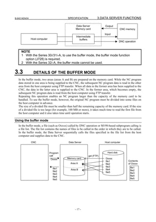
- 15 -](https://image.slidesharecdn.com/b-64014en04-121129012902-phpapp02/85/B-64014-en-04-27-320.jpg)


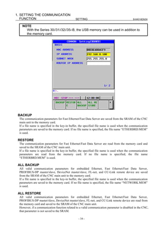
![1.SETTING THE COMMUNICATION
B-64014EN/04 SETTING FUNCTION
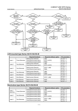
1 SETTING THE COMMUNICATION
FUNCTION
This part describes the settings required to operate the following Fast Ethernet/Fast Data Server functions:
• Data Server functions
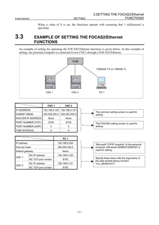
• FOCAS2/Ethernet functions
• CNC screen display functions
• Machine remote diagnosis functions
• Unsolicited messaging function
• FTP file transfer function
Notes on using the functions for the first time
CAUTION
When setting the Fast Ethernet/Fast Data Server for the first time, carefully set
data such as an IP address and conduct a sufficient communication test,
consulting with your network administrator.
If data such as an IP address is not set correctly, a communication failure can
affect the entire network. Take sufficient care.
The load on the network may become greater than expected depending on the
performance of the personal computer. Before using the functions, completely
confirm that there is no problem with the entire system including communication
with the personal computer.
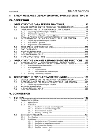
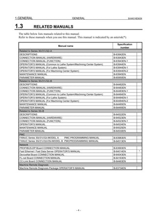
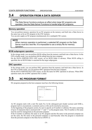
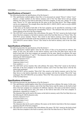
1.1 BACKING UP/RESTORING COMMUNICATION
PARAMETERS
This section explains how to back up communication parameters for Fast Ethernet/Fast Data Server to the
memory card and to restore them from the memory card.
1 Press the function key .
2 Soft key [ETHER BOARD] ([ETHER NET] for the Series 30i/31i/32i/35i-B) appear. (When there is
no soft keys, press the continue key.)
3 Press soft key [ETHER BOARD] to display the Ethernet Setting screen.
4 Press the soft keys [COMMON] - [(OPRT)] and then [+]. The soft keys [BACKUP], [RESTORE],
[ALL BACKUP], and [ALL RESTORE] for backing up or restoring communication parameters
appear.
5 Press the soft key [BACKUP], [RESTORE], [ALL BACKUP], or [ALL RESTORE]. The soft keys
[EXECUTE] and [CANCEL] appear.
6 Enter the name of a file to be backed up or restored in the key-in buffer, and press the soft key
[EXECUTE]. The operation selected at the above step is executed.
The character string “EXECUTING” blinks during execution.
- 33 -](https://image.slidesharecdn.com/b-64014en04-121129012902-phpapp02/85/B-64014-en-04-45-320.jpg)
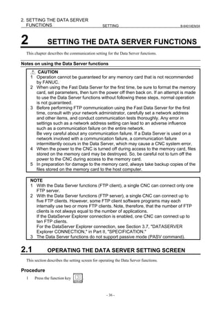
![1.SETTING THE COMMUNICATION
B-64014EN/04 SETTING FUNCTION
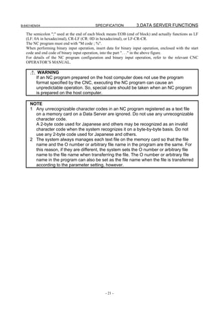
If a file name is specified in the key-in buffer, the specified file name is used when the parameters are
read from the memory card. If no file name is specified, the file name “NETWORK.MEM” is used.
CAUTION
While an external input/output device such as the memory card or USB memory
is being accessed, do not turn the power to the CNC off or remove the external
input/output device. Doing so may damage the external input/output device.
NOTE
1 A backup or restore operation for communication parameters can only be
performed in the MDI mode, EDIT mode, or emergency stop state.
2 When communication parameters are restored, an alarm condition occurs that
requires power-off.
Related NC parameters
0020 I/O CHANNEL: Input/output device selection, or interface number for a foreground input/output device
[Input type] Setting input
[Data type] Byte
[Valid data range] 4: Selects the memory card as the input/output device.
17: Selects the USB memory as the input/output device.
It is not possible to backup and restore the communication parameters by using other
devices.
NOTE
In case of Series 30i/31i/32i-A, the memory card is used
regardless for this NC parameter.
- 35 -](https://image.slidesharecdn.com/b-64014en04-121129012902-phpapp02/85/B-64014-en-04-47-320.jpg)
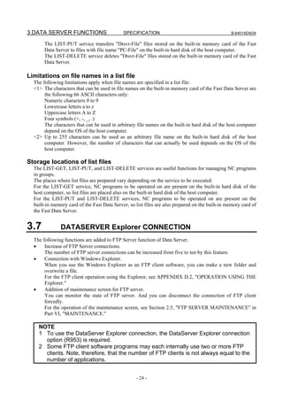
![2.SETTING THE DATA SERVER
B-64014EN/04 SETTING FUNCTIONS
2 Soft key [ETHER BOARD] ([ETHER NET] for the Series 30i/31i/32i/35i-B) appear. (When there is
no soft keys, press the continue key.)
3 Press soft key [ETHER BOARD] to display the Ethernet Setting screen.
4 Press soft keys [COMMON] and [DATA SERVER] and then enter parameters for the items that
appear.
COMMON screen (BASIC)
Press soft key [COMMON] to display the COMMON screen (BASIC).
COMMON screen (BASIC)
Setting item
Item Description
IP ADDRESS Specify the IP address of the Fast Data Server.
(Example of specification format: "192.168.0.100")
SUBNET MASK Specify a mask address for the IP addresses of the network.
(Example of specification format: "255.255.255.0")
ROUTER IP ADDRESS Specify the IP address of the router.
Specify this item when the network contains a router.
(Example of specification format: "192.168.0.253")
Display item
Item Description
MAC ADDRESS Fast Ethernet/Fast Data Server MAC address
NOTE
The second page (detail screen) of the COMMON screen is to be set when the
DNS/DHCP function is used. For details, see "SETTING THE DNS/DHCP
FUNCTION" provided later.
Data Server screens (CONNECT 1, CONNECT 2, CONNECT 3)
Press soft key [DATA SERVER] to display the Data Server screen.
By using page keys , the three host computers at connection destinations 1, 2, and 3 can be
set.
- 37 -](https://image.slidesharecdn.com/b-64014en04-121129012902-phpapp02/85/B-64014-en-04-49-320.jpg)
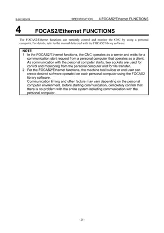
![2. SETTING THE DATA SERVER
FUNCTIONS SETTING B-64014EN/04
Data Server screens (for connection destination 1)
Setting item
Item Description
HOST NAME Specify the IP address of the host computer.
(Example of specification format: "192.168.0.200")
PORT NUMBER Specify the port number. Usually, set 21 because the FTP communication is used.
USER NAME Specify the name of the user to log on to the host computer using FTP. (A user
name of up to 31 characters can be specified.)
PASSWORD Specify the password for the above user name.
The password must always be specified.
LOGIN FOLDER Specify a work folder to be used when the user logs in to the host computer. (Up to
127 characters can be specified.)
If no data is set, the home folder set on the host computer is used as a login folder.
Operation
Select a connection destination.
1 Press soft key [(OPRT)] to display soft key [HOST SELECT]. Then, press soft key [HOST
SELECT] to display soft keys [CONECT 1], [CONECT 2], and [CONECT 3].
2 Press one of soft keys [CONECT 1], [CONECT 2], and [CONECT 3] according to the host
computer to which you want to make a connection. The screen title of connection destination 1, 2 or
3 is displayed in reverse video. The screen title displayed in reverse video indicates the connection
destination host computer.
When connection destination 1 is selected
- 38 -](https://image.slidesharecdn.com/b-64014en04-121129012902-phpapp02/85/B-64014-en-04-50-320.jpg)
![2.SETTING THE DATA SERVER
B-64014EN/04 SETTING FUNCTIONS
Data Server screens (FTP SERVER)
Press soft key [DATA SERVER] to display the Data Server screen.
By using page keys , the FTP server setting screen is displayed after the connection
destination 1, 2, or 3 screen.
Data Server screens (FTP SERVER)
Setting item
Item Description
USER NAME Specify a user name to be used when the host computer logs in to the Data Server.
(A user name of up to 31 characters can be specified.)
PASSWORD Specify the password for the above user name.
The password must always be specified.
LOGIN FOLDER Specify a work folder to be used when the host computer logs in to the Data Server.
(Up to 127 characters can be specified.)
If no data is set, the home folder (home directory) is used as a login folder.
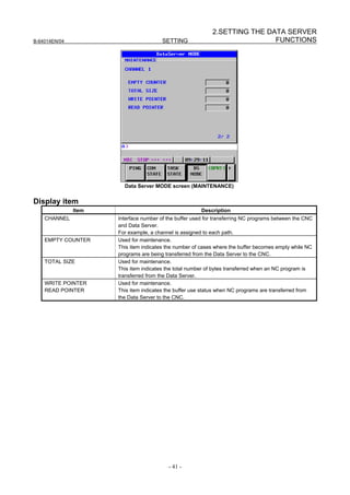
Data Server MODE screen (SETTING)
Press soft key [DS MODE] to display the Data Server MODE screen (SETTING). The current mode can
be checked and changed.
- 39 -](https://image.slidesharecdn.com/b-64014en04-121129012902-phpapp02/85/B-64014-en-04-51-320.jpg)
![2. SETTING THE DATA SERVER
FUNCTIONS SETTING B-64014EN/04
Data Server screen (SETTING)
Display item
Item Description
CHANNELS Displays the number of channels currently being used.
MODE Displays the currently set Data Server mode.
STORAGE MODE
FTP MODE
BUFFER MODE
Operation
The Data Server mode can be changed.
1 Press soft key [(OPRT)] to display soft keys [STRAGE MODE], [FTP MODE], and [BUFFER
MODE].
2 To change the mode to a desired mode, press the soft key of the desired mode.
NOTE
1 With the Series 30i/31i-A, to use the buffer mode, the buffer mode function
option (J728) is required.
2 With the Series 32i-A, the buffer mode cannot be used.
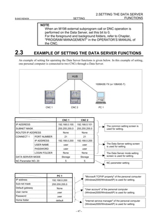
Data Server MODE screen (MAINTENANCE)
Press soft key [DS MODE] and press page keys to display maintenance information for each
channel.
- 40 -](https://image.slidesharecdn.com/b-64014en04-121129012902-phpapp02/85/B-64014-en-04-52-320.jpg)
![2. SETTING THE DATA SERVER
FUNCTIONS SETTING B-64014EN/04
Data Server FORMAT screen
Press soft key [DS FORMAT] to display the format screen of the memory card built into the Data Server.
Data Server FORMAT screen
Display item
Item Description
DEVICE NAME Indicates the storage media currently being used by the Data Server.
"ATA" or "NONE" is indicated.
ATA : A memory card is mounted.
None : No memory card is mounted.
FORMAT TYPE Indicates the format type of the memory card.
"CNC FILE" or "---" is displayed.
When "---" is displayed, check whether the memory card is mounted properly and is
formatted correctly.
CHECK DISK Indicates the check result.
When no check is made : “-----“
When the check result is normal : “OK”
When the check result is abnormal : “NG”
Procedure (CHECK DISK)
1 Press soft key [(OPRT)] then soft key [CHECK DISK].
2 Press soft key [EXEC] to check the format of the memory card and display the check result.
CAUTION
If the check result is abnormal, determine the cause of trouble from an error
message displayed on the ETHERNET LOG screen and back up the files stored
on the memory card immediately. Then, try to reformat the memory card.
- 42 -](https://image.slidesharecdn.com/b-64014en04-121129012902-phpapp02/85/B-64014-en-04-54-320.jpg)
![2.SETTING THE DATA SERVER
B-64014EN/04 SETTING FUNCTIONS
NOTE
1 An error occurs if other Data Server functions are operated when a check disk is
made.
2 Also when a program on the memory card of the Data Server is selected as a
main program, the check disk operation cannot be performed.
Procedure (CNC FORMAT)
1 Press soft key [(OPRT)] then soft key [CNC FORMAT].
2 Press soft key [EXEC] to format the memory card built into the Fast Data Server.
CAUTION
1 Do not turn off the power to the CNC when the memory card is being formatted.
Otherwise, the memory card can be damaged.
2 When the memory card is formatted, all files held on the memory card are
erased.
NOTE
1 An error occurs if other Data Server functions are operated when the memory
card is formatted.
2 Also when a program on the memory card of the Data Server is selected as a
main program, the memory card cannot be formatted.
2.2 RELATED NC PARAMETERS
The NC parameters related to the Data Server functions are described below.
#7 #6 #5 #4 #3 #2 #1 #0
0000 TVC
[Input type] Setting input
[Data type] Bit path
#0 TVC When a file is transferred from the personal computer to the Data Server, a TV check is:
0: Not performed.
1: Performed.
NOTE
This parameter is valid only for text files.
For text files, see Subsection 3.1.3, "Text Files and Binary Files" in
Part II, "SPECIFICATION."
0020 I/O CHANNEL : Input/output device selection
[Input type] Setting input
[Data type] Byte
[Valid data range] 5 : Selects the Data Server as the input/output device.
#7 #6 #5 #4 #3 #2 #1 #0
0100 NCR CRF CTV
[Input type] Setting input
- 43 -](https://image.slidesharecdn.com/b-64014en04-121129012902-phpapp02/85/B-64014-en-04-55-320.jpg)
![2. SETTING THE DATA SERVER
FUNCTIONS SETTING B-64014EN/04
[Data type] Bit
#1 CTV When a file is transferred from the personal computer to the Data Server, character
counting for the TV check in program comment parts is:
0: Performed.
1: Not performed.
#2 CRF When a file is output from the Data Server to the personal computer, EOB (end of block)
is:
0: Set as specified by parameter NCR (bit 3 of parameter No. 100).
1: Set to "CR" "LF".
#3 NCR When a file is output from the Data Server to the personal computer, EOB (end of block)
is:
0: Set to "LF" "CR" "CR".
1: Set to "LF".
NOTE
This parameter is valid only for text files.
For text files, see Subsection 3.1.3, "Text Files and Binary Files" in
Part II, "SPECIFICATION."
#7 #6 #5 #4 #3 #2 #1 #0
0904 LCH BWT
[Input type] Parameter input
[Data type] Bit
#0 BWT If FTP communication is behind data supply during DNC operation in the buffer mode of
the Data Server:
0: An error is caused.
1: No error is caused and DNC operation continues after waiting the completion of
FTP communication.
#7 LCH In the LIST-GET service of the Data Server, when a list file specifies 1025 or more files:
0: A check for duplicated file names is performed.
1: A check for duplicated file names is not performed.
#7 #6 #5 #4 #3 #2 #1 #0
0905 DSF PCH
[Input type] Parameter input
[Data type] Bit
#1 PCH At the start of communication of the Data Server, FTP file transfer function, or machine
remote diagnosis functions, checking for the presence of the server using PING is:
0: Performed.
1: Not performed.
NOTE
Usually, set Performed (0).
When the presence of the server using PING is not checked by
setting 1, it may take several tens of seconds until an error is
recognized due to no server on the network.
For mainly security reasons, a personal computer may be set so
that it does not respond to the PING command. Set 1 when the
Data Server communicates with such a personal computer.
#3 DSF When an NC program is stored on the memory card of the Data Server:
0: The file name takes priority.
1: The program name in the NC program takes priority.
- 44 -](https://image.slidesharecdn.com/b-64014en04-121129012902-phpapp02/85/B-64014-en-04-56-320.jpg)
![2.SETTING THE DATA SERVER
B-64014EN/04 SETTING FUNCTIONS
NOTE
This parameter is valid only when files on a personal computer are
registered as text files on the memory card on the Data Server by
CNC operation.
#7 #6 #5 #4 #3 #2 #1 #0
0906 SCM OVW
[Input type] Parameter input
[Data type] Bit
#2 OVW When the Data Server is operated as an FTP server, if a file having the same name as a
file to be transferred from the FTP client is already stored in the memory card of Data
Server:
0: An error is caused.
1: No error is caused and the existing file is overwritten.
NOTE
To use this parameter, the DataServer Explorer connection option
is required.
#5 SCM As the mode for accessing the memory card on the Data Server:
0: The mode supported by the memory card that is automatically determined is used.
1: The conventional PIO mode 2 is used.
NOTE
1 When this parameter is set, the power must be turned off before
operation is continued.
2 This parameter is only available with the Series 30i/31i/32i-B.
0921 Selects the host computer 1 OS.
0922 Selects the host computer 2 OS.
0923 Selects the host computer 3 OS.
[Input type] Parameter input
[Data type] Word
[Valid data range] 0 to 2
0: Windows95/98/Me/NT/2000/XP/Vista/7.
1: UNIX/VMS.
2: Linux.
NOTE
Some FTP server software may not depend on the OS. Therefore,
the valid file list may not be displayed by the above setting.
0924 FOCAS2/Ethernet function wait time setting
[Input type] Parameter input
[Data type] Word
[Unit of data] msec
[Valid data range] 0 to 32767
Specifies the wait time (in 1 ms units) for the FOCAS2/Ethernet service when it is used
together with the Data Server functions.
If 0 is specified, a wait time of 1 ms is assumed.
- 45 -](https://image.slidesharecdn.com/b-64014en04-121129012902-phpapp02/85/B-64014-en-04-57-320.jpg)
![2. SETTING THE DATA SERVER
FUNCTIONS SETTING B-64014EN/04
0929 Specifies the attribute of the file to be transferred in operating as an FTP server.
[Input type] Parameter input
[Data type] Word
[Valid data range] 0 to 2
Specifies whether to use the file attribute specified in the FTP TYPE command when the
Data Server operates as an FTP server.
No.929 Meaning
0 Uses the file attribute specified in the TYPE command from the FTP client.
1 Fixes the attribute to text.
2 Fixes the attribute to binary.
Maximum number of files that can be registered to the memory card of the Data Server and maximum
0930
size per file that can be registered
[Input type] Parameter input
[Data type] Word
[Valid data range] 0, 10 to 15
No.930 Maximum number of files Maximum size per file
0 2047 512MB
10 511 2048MB
11 1023 1024MB
12 2047 512MB
13 4095 256MB
14 8191 128MB
15 16383 64MB
NOTE
1 When the memory card is formatted after this parameter is set, the
maximum number of files and maximum size per file are changed.
2 Each folder is counted as one file.
3 This parameter is valid when the series and edition of the Data
Server function software are edition 11 or later of series 6569.
#7 #6 #5 #4 #3 #2 #1 #0
3107 SOR
[Input type] Setting input
[Data type] Bit path
#4 SOR In the Data Server FILE LIST screen, files are displayed:
0: In the order of zero-suppressed program number.
1: In the order of program name.
#7 #6 #5 #4 #3 #2 #1 #0
3233 PDM
[Input type] Parameter input
[Data type] Bit
#1 PDM When the Data Server FILE LIST screen is displayed:
0: The setting of an M198 operation folder/DNC operation file is enabled.
1: The setting of a foreground/background folder is enabled.
- 46 -](https://image.slidesharecdn.com/b-64014en04-121129012902-phpapp02/85/B-64014-en-04-58-320.jpg)
![3. SETTING THE FOCAS2/Ethernet
FUNCTIONS SETTING B-64014EN/04
3 SETTING THE FOCAS2/Ethernet
FUNCTIONS
This chapter describes the setting of parameters for the FOCAS2/Ethernet functions and CNC screen
display functions.
CAUTION
Before performing communication using the FOCAS2/Ethernet functions for the
first time, consult with your network administrator, carefully set a network
address and other items, and conduct communication tests thoroughly. Any error
in settings such as a network address setting can lead to an adverse influence
such as a communication failure on the entire network.
Be very careful about any communication failure. If the FOCAS2/Ethernet
functions are used on a network involved with a communication failure, a
communication failure intermittently occurs in FOCAS2/Ethernet, which may
cause a CNC system error.
Note on using the FOCAS2/Ethernet functions
NOTE
With the FOCAS2/Ethernet functions, up to 20 FOCAS2/Ethernet clients can be
connected to one CNC.
Note on using the CNC screen display functions
NOTE
With the CNC screen display functions, up to 1 CNC screen display function
client can be connected to one CNC.
3.1 OPERATING THE FOCAS2/Ethernet SETTING SCREEN
This section describes the setting screen for operating the FOCAS2/Ethernet functions and CNC screen
display functions.
Procedure
1 Press the function key .
2 Soft key [ETHER BOARD] ([ETHER NET] for the Series 30i/31i/32i/35i-B) appear. (When there is
no soft keys, press the continue key.)
3 Press soft key [ETHER BOARD] to display the Ethernet Setting screen.
4 Press soft keys [COMMON] and [FOCAS2] and then enter parameters for the items that appear.
- 48 -](https://image.slidesharecdn.com/b-64014en04-121129012902-phpapp02/85/B-64014-en-04-60-320.jpg)
![3.SETTING THE FOCAS2/Ethernet
B-64014EN/04 SETTING FUNCTIONS
COMMON screen (BASIC)
Press soft key [COMMON] to display the COMMON screen (BASIC).
COMMON screen (BASIC)
Setting item
Item Description
IP ADDRESS Specify the IP address of the Fast Ethernet/ Fast Data Server.
(Example of specification format: "192.168.0.100")
SUBNET MASK Specify a mask address for the IP addresses of the network.
(Example of specification format: "255.255.255.0")
ROUTER IP ADDRESS Specify the IP address of the router.
Specify this item when the network contains a router.
(Example of specification format: "192.168.0.253")
Display item
Item Description
MAC ADDRESS Fast Ethernet/ Fast Data Server MAC address
NOTE
The second page (detail screen) of the COMMON screen is to be set when the
DNS/DHCP function is used. For details, see Chapter 4, "SETTING THE
DNS/DHCP FUNCTION" provided later.
- 49 -](https://image.slidesharecdn.com/b-64014en04-121129012902-phpapp02/85/B-64014-en-04-61-320.jpg)
![3. SETTING THE FOCAS2/Ethernet
FUNCTIONS SETTING B-64014EN/04
FOCAS2 screen
Press soft key [FOCAS2] to display the FOCAS2 screen.
FOCAS2 screen
Setting item
Item Description
PORT NUMBER (TCP) Specifies the port No. to be used by the FOCAS2/Ethernet functions and CNC
screen display functions, within a range of 5001 to 65535.
PORT NUMBER (UDP) Set 0.
TIME INTERVAL Set 0.
3.2 RELATED NC PARAMETERS
0020 I/O CHANNEL : Input/output device selection
[Input type] Setting input
[Data type] Byte
[Valid data range] 6 : Selects the FOCAS2/Ethernet as the input/output device. This parameter is required
only for DNC operation, however.
#7 #6 #5 #4 #3 #2 #1 #0
0905 DNE
[Input type] Parameter input
[Data type] Bit
#1 DNE During DNC operation using the FOCAS2/Ethernet functions, the termination of DNC
operation is:
0: Waited.
1: Not waited. (FOCAS2/HSSB compatible specification)
0924 FOCAS2/Ethernet waiting time setting
[Input type] Parameter input
[Data type] Word
[Unit of data] msec
[Valid data range] 0 to 32767
When the FOCAS2/Ethernet and Data Server functions are used simultaneously, this
parameter sets the FOCAS2/Ethernet function waiting time in milliseconds.
- 50 -](https://image.slidesharecdn.com/b-64014en04-121129012902-phpapp02/85/B-64014-en-04-62-320.jpg)
![4.SETTING THE DNS/DHCP
FUNCTION SETTING B-64014EN/04
4 SETTING THE DNS/DHCP FUNCTION
This chapter describes the setting of the DNS/DHCP function.
4.1 SETTING OF DNS
This section describes the setting procedure for operating DNS client function.
Procedure
1 Enable the DNS client function according to Section 4.3, "RELATED NC PARAMETERS"
provided later.
2 Set up the DNS server on the host computer. For information about setup, see Appendix C,
"EXAMPLE OF DNS/DHCP SETUP."
3 Make a connection to the host computer where the DNS server operates (hereinafter referred to as
the "DNS server") and restart the CNC, then press the function key .
4 Press soft key [ETHER BOARD] ([ETHER NET] for the Series 30i/31i/32i/35i-B), then press
[COMMON] to display the COMMON (DETAIL) screen.
5 As the DNS IP address, enter the IP address of the DNS server.
COMMON screen (DETAIL)
Press soft key [COMMON] then page keys to display the COMMON (DETAIL) screen. Set
the setting items for DNS IP addresses.
COMMON screen (DETAIL)
Setting item
Item Description
DNS IP ADDRESS 1, 2 Up to two DNS server IP addresses can be set.
The CNC searches for a DNS server in the order from DNS IP address 1 to 2.
- 52 -](https://image.slidesharecdn.com/b-64014en04-121129012902-phpapp02/85/B-64014-en-04-64-320.jpg)
![4.SETTING THE DNS/DHCP
B-64014EN/04 SETTING FUNCTION
4.2 SETTING OF DHCP
This section describes the setting procedure for operating DHCP client function.
Procedure
1 Enable the DHCP client function according to Section 4.3 "RELATED NC PARAMETERS"
provided later.
2 Set up the DHCP server on the host computer. For information about setup, see Appendix C,
"EXAMPLE OF DNS/DHCP SETUP."
3 Make a connection to the host computer where the DHCP server operates (hereinafter referred to as
the "DHCP server") and restart the CNC, then press the function key .
4 Press soft key [ETHER BOARD] ([ETHER NET] for the Series 30i/31i/32i/35i-B), then press
[COMMON] to display the COMMON screen.
5 If the DHCP client function of the CNC is enabled and a connection is made successfully with the
DHCP server, the following items are set automatically from the DHCP server:
• IP ADDRESS
• SUBNET MASK
• ROUTER IP ADDRESS
• DNS IP ADDRESS
• DOMAIN
If an attempt to make a connection with the DHCP server fails, "DHCP ERROR" is indicated in each
item.
6 Moreover, if the DNS client function is enabled at the same time and the DHCP server interacts with
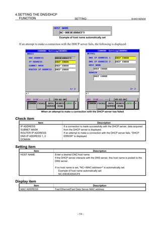
the DNS server (the DNS server supports dynamic DNS), enter a desired host name.
COMMON screens (BASIC, DETAIL)
Press soft key [COMMON] then page keys to display the COMMON screens (BASIC and
DETAIL). If a connection is made successfully with the DHCP server and setting data is acquired, the
following is displayed:
When a connection with the DHCP server has been made successfully
If no host name is set, the CNC automatically sets a host name in the format "NC-<MAC address>".
- 53 -](https://image.slidesharecdn.com/b-64014en04-121129012902-phpapp02/85/B-64014-en-04-65-320.jpg)
![4.SETTING THE DNS/DHCP
B-64014EN/04 SETTING FUNCTION
4.3 RELATED NC PARAMETERS
#7 #6 #5 #4 #3 #2 #1 #0
0904 DHCP DNS
[Input type] Parameter input
[Data type] Bit
#5 DNS The DNS client function is:
0: Not used.
1: Used.
#6 DHC The DHCP client function is:
0: Not used.
1: Used.
NOTE
When at least one of these parameters is set, the power must be
turned off before operation is continued.
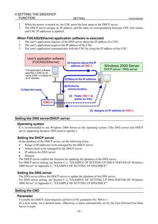
4.4 EXAMPLE OF SETTING DNS/DHCP
NOTE
This section provides examples of setting for Windows 2000 Server which
supports dynamic DNS.
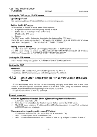
4.4.1 When DNS/DHCP is Used with the Data Server
When a connection is made with the FTP server of the host computer (hereinafter referred to as the "FTP
server") by using the Data Server function, the IP address of the CNC can be set from the DHCP server
by enabling the DHCP client function of the CNC.
Moreover, by enabling the DNS client function of the CNC, an FTP server can be specified with a host
name instead of an IP address.
Example of specifying a connection destination with a host name (FTPServer-1)
- 55 -](https://image.slidesharecdn.com/b-64014en04-121129012902-phpapp02/85/B-64014-en-04-67-320.jpg)

![5. SETTING THE MACHINE REMOTE
DIAGNOSIS FUNCTIONS SETTING B-64014EN/04
5 SETTING THE MACHINE REMOTE
DIAGNOSIS FUNCTIONS
This chapter describes the setting of parameters for the machine remote diagnosis functions.
For explanation of the entire machine remote diagnosis functions, refer to "Machine Remote Diagnosis
Package OPERATOR'S MANUAL (B-63734EN)."
5.1 OPERATING THE MACHINE REMOTE DIAGNOSIS
SETTING SCREEN
This section describes the setting screen for operating the machine remote diagnosis functions.
Procedure
1 Press the function key .
2 Soft key [ETHER BOARD] ([ETHER NET] for the Series 30i/31i/32i/35i-B) appear. (When there is
no soft keys, press the continue key.)
3 Press soft key [ETHER BOARD] to display the Ethernet Setting screen.
4 Press soft keys [COMMON], [FOCAS2], and [REMOTE DIAG] and then enter parameters for the
items that appear.
COMMON screen (BASIC)
Press soft key [COMMON] to display the COMMON screen (BASIC).
COMMON screen (BASIC)
Setting item
Item Description
IP ADDRESS Specify the IP address of the Fast Ethernet / Fast Data Server.
(Example of specification format: "192.168.0.100")
SUBNET MASK Specify a mask address for the IP addresses of the network.
(Example of specification format: "255.255.255.0")
- 60 -](https://image.slidesharecdn.com/b-64014en04-121129012902-phpapp02/85/B-64014-en-04-72-320.jpg)
![5.SETTING THE MACHINE REMOTE
B-64014EN/04 SETTING DIAGNOSIS FUNCTIONS
Item Description
ROUTER IP ADDRESS Specify the IP address of the router.
Specify this item when the network contains a router.
(Example of specification format: "192.168.0.253")
Display item
Item Description
MAC ADDRESS Fast Ethernet / Fast Data Server MAC address
NOTE
The second page (detail screen) of the COMMON screen is to be set when the
DNS/DHCP function is used. For details, see Chapter 4 "SETTING THE
DNS/DHCP FUNCTION".
COMMON screen (DETAIL)
Press soft key [COMMON] then page keys to display the COMMON (DETAIL) screen. Set
the setting items for DNS IP addresses.
COMMON screen (DETAIL)
Setting item
Item Description
DNS IP ADDRESS 1, 2 Up to two DNS server IP addresses can be set.
The CNC searches for a DNS server in the order from DNS IP address 1 to 2.
- 61 -](https://image.slidesharecdn.com/b-64014en04-121129012902-phpapp02/85/B-64014-en-04-73-320.jpg)
![5. SETTING THE MACHINE REMOTE
DIAGNOSIS FUNCTIONS SETTING B-64014EN/04
FOCAS2 screen
Press soft key [FOCAS2] to display the FOCAS2 screen.
FOCAS2 screen
Setting item
Item Description
PORT NUMBER (TCP) Specifies the port No. to be used by the machine remote diagnosis functions
(FOCAS2/Ethernet functions), within a range of 5001 to 65535.
PORT NUMBER (UDP) Set 0.
TIME INTERVAL Set 0.
MACHINE REMOTE DIAG screen (COMMON)
Press soft key [REMOTE DIAG] to display the MACHINE REMOTE DIAG screen (COMMON).
Machine remote diagnosis screen (BASIC)
- 62 -](https://image.slidesharecdn.com/b-64014en04-121129012902-phpapp02/85/B-64014-en-04-74-320.jpg)
![5.SETTING THE MACHINE REMOTE
B-64014EN/04 SETTING DIAGNOSIS FUNCTIONS
Setting item
Item Description
MTB ID This information is required by the machine remote diagnosis package to confirm that
the diagnosis request is issued from a machine manufactured by the machine tool
builder. The MTB identification information on the diagnosis accepting server of the
machine remote diagnosis package can be set to accept diagnosis requests only from
the machines manufactured by the machine tool builder.
(Example of specification format: "FANUC")
MACHINE ID Information required by the machine remote diagnosis package to identify the machine
under diagnosis
(Example of specification format: "217xxx-1011xxxxx")
MACHINE REMOTE DIAG screen (INQUIRY1, INQUIRY2, INQUIRY3)
Press soft key [REMOTE DIAG] to display the MACHINE REMOTE DIAG screen.
By using page keys , the three host computers at inquiry destinations 1, 2, and 3 can be set.
MACHINE REMOTE DIAG screens (INQUIRY1):
Screen when the DNS function is disabled (left) and screen when the function is enabled (right)
Setting item
Item Description
HOST NAME Specify the IP address of the host computer (machine remote diagnosis accepting
server) when the DNS function is disabled.
(Example of specification format: "200.201.202.203")
Specify the host name of the host computer (machine remote diagnosis accepting
server) when the DNS function is enabled. (You can specify up to 63 characters.)
(Example of specification format: "RMTDIAG.FANUC.CO.JP")
PORT NUMBER Specify a port number. Usually, specify "8194" because the machine remote diagnosis
functions are used.
INQUIRY NAME Specify information for identifying the host computer (machine remote diagnosis
accepting server). (You can specify up to 63 characters.)
(Example of specification format: "FANUC LTD.")
- 63 -](https://image.slidesharecdn.com/b-64014en04-121129012902-phpapp02/85/B-64014-en-04-75-320.jpg)
![5. SETTING THE MACHINE REMOTE
DIAGNOSIS FUNCTIONS SETTING B-64014EN/04
5.2 RELATED NC PARAMETERS
0024 Setting of communication with the PMC ladder development tool
[Input type] Setting input
[Data type] Byte
[Valid data range] 10: The high-speed interface (Ethernet) is used for PMC online editing.
#7 #6 #5 #4 #3 #2 #1 #0
0904 DNS
[Input type] Parameter input
[Data type] Bit
#5 DNS The DNS function is:
0: Not used.
1: Used.
NOTE
1 When this parameter is set, the power must be turned off before
operation is continued.
2 To use the DNS function, set DNS IP ADDRESS 1 and DNS IP
ADDRESS 2 on the COMMON (DETAIL) screen.
#7 #6 #5 #4 #3 #2 #1 #0
0905 PCH
[Input type] Parameter input
[Data type] Bit
#1 PCH At the start of communication of the Data Server, FTP file transfer function, or machine
remote diagnosis functions, checking for the presence of the server using PING is:
0: Performed.
1: Not performed.
NOTE
Usually, set Performed (0).
When the presence of the server using PING is not checked by
setting 1, it may take several tens of seconds until an error is
recognized due to no server on the network.
For mainly security reasons, a personal computer may be set so
that it does not respond to the PING command. Set 1 when the
Data Server communicates with such a personal computer.
#7 #6 #5 #4 #3 #2 #1 #0
8706 MRD
[Input type] Parameter input
[Data type] Bit
#6 MRD Type of communication device to be used by the machine remote diagnosis function:
0: The machine remote diagnosis function is not used.
1: The Fast Ethernet board is used.
NOTE
When this parameter is set, the power must be turned off before
operation is continued.
- 64 -](https://image.slidesharecdn.com/b-64014en04-121129012902-phpapp02/85/B-64014-en-04-76-320.jpg)
![5.SETTING THE MACHINE REMOTE
B-64014EN/04 SETTING DIAGNOSIS FUNCTIONS
5.3 CONTROLLING THE MACHINE REMOTE DIAGNOSIS
FUNCTIONS FROM THE PMC
You can use signals from the PMC to control the start and forced termination of the machine remote
diagnosis functions and post the status of the machine remote diagnosis functions and error numbers to
the PMC ladder.
5.3.1 Signals
No. #7 #6 #5 #4 #3 #2 #1 #0
G0141 DIAREQ DIASTP INQU2 INQU1 INQU0
DIAREQ <G0141.5>
[Name] Signal to request machine remote diagnosis
[Classification] Input signal
[Function] Requests the start of machine remote diagnosis.
[Operation] When this signal is set to "1", it requests the start of machine remote diagnosis to the
inquiry destination according to the signals indicating the number of the inquiry
destination (INQU0 to INQU2). When the acceptance completion signal (RMTEND) or
acceptance reject signal (RMTCAN) is set to "1", this signal is set to "0".
DIASTP <G0141.4>
[Name] Signal to request machine remote diagnosis cancellation
[Classification] Input signal
[Function] Requests the forced termination of machine remote diagnosis.
[Operation] When this signal is set to "1", it requests forced termination to the machine remote
diagnosis accepting server. When the completion signal for machine remote signal cancel
acceptance (RMTCLS) is set to "1", this signal is set to "0".
INQU2 <G0141.2>
INQU1 <G0141.1>
INQU0 <G0141.0>
[Name] Inquiry number select signals
[Classification] Input signal
[Function] Inquiry destination for which to start machine remote diagnosis
[Operation] Select an item from the table below as an inquiry destination for which to start machine
remote signal.
INQU2 INQU1 INQU0 Status
0 0 0 No selection
0 0 1 Inquiry destination 1
0 1 0 Inquiry destination 2
0 1 1 Inquiry destination 3
No. #7 #6 #5 #4 #3 #2 #1 #0
F0082 RMTCLS
RMTCLS <F0082.3>
[Name] Completion signal for machine remote diagnosis cancel acceptance
[Classification] Output signal
[Function] Notifies that a request to cancel machine remote diagnosis has been accepted.
- 65 -](https://image.slidesharecdn.com/b-64014en04-121129012902-phpapp02/85/B-64014-en-04-77-320.jpg)
![5. SETTING THE MACHINE REMOTE
DIAGNOSIS FUNCTIONS SETTING B-64014EN/04
[Output condition] When machine remote diagnosis is canceled after the signal to request machine remote
diagnosis cancellation (DIASTP) is set to "1", this signal is set to "1". When the signal to
request machine remote diagnosis cancellation (DIASTP) is set to "0", this signal is set to
"0".
No. #7 #6 #5 #4 #3 #2 #1 #0
F0083 RMTCAN RMTEND DIAST5 DIAST4 DIAST3 DIAST2 DIAST1 DIAST0
RMTCAN <F0083.7>
[Name] Reject signal for machine remote diagnosis acceptance
[Classification] Output signal
[Function] Notifies that a machine remote diagnosis request has been rejected.
[Output condition] When the signal to request machine remote diagnosis (DIAREQ) is set to "1", a request to
start machine remote diagnosis is issued to the machine remote diagnosis accepting server.
When the server rejects the request, this signal is set to "1". When the signal to request
machine remote diagnosis (DIAREQ) is set to "0", this signal is set to "0".
RMTEND <F0083.6>
[Name] Completion signal for machine remote diagnosis acceptance
[Classification] Output signal
[Function] Notifies that a machine remote diagnosis request has been accepted by the machine
remote diagnosis accepting server.
[Output condition] When the signal to request machine remote diagnosis (DIAREQ) is set to "1", a request to
start machine remote diagnosis is issued to the machine remote diagnosis accepting server.
When the server accepts the request, this signal is set to "1". When the signal to request
machine remote diagnosis (DIAREQ) is set to "0", this signal is set to "0".
DIAST5 <F0083.5>
DIAST4 <F0083.4>
DIAST3 <F0083.3>
DIAST2 <F0083.2>
DIAST1 <F0083.1>
DIAST0 <F0083.0>
[Name] Notification signals for the machine remote diagnosis status
[Classification] Output signal
[Function] Report the status of machine remote diagnosis.
[Output condition] The status of machine remote diagnosis is reported as listed in the following table.
DIAST5 DIAST4 DIAST3 DIAST2 DIAST1 DIAST0 Description
0 0 0 0 0 0 No status
0 0 0 0 0 1 OPEN
0 0 0 0 1 0 OPENING
0 0 0 0 1 1 ACCEPTED
0 0 0 1 0 0 REFUSED
0 0 0 1 0 1 DIAGNOSING
0 0 0 1 1 0 DIAGNOSING
0 0 0 1 1 1 CLOSE
0 0 1 0 0 0 FORCE CLOSING
0 0 1 0 0 1 ERROR
No. #7 #6 #5 #4 #3 #2 #1 #0
F0088 DIAER7 DIAER6 DIAER5 DIAER4 DIAER3 DIAER2 DIAER1 DIAER0
DIAER7 <F0088.7>
- 66 -](https://image.slidesharecdn.com/b-64014en04-121129012902-phpapp02/85/B-64014-en-04-78-320.jpg)
![5.SETTING THE MACHINE REMOTE
B-64014EN/04 SETTING DIAGNOSIS FUNCTIONS
DIAER6 <F0088.6>
DIAER5 <F0088.5>
DIAER4 <F0088.4>
DIAER3 <F0088.3>
DIAER2 <F0088.2>
DIAER1 <F0088.1>
DIAER0 <F0088.0>
[Name] Notification signals for a machine remote diagnosis error number
[Classification] Output signal
[Function] Report an error number of machine remote diagnosis.
[Output condition] These signals indicate an error number of machine remote diagnosis. The error number is
0 to 255 in binary format.
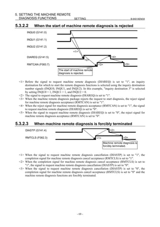
5.3.2 Signal Timing Charts
This section describes control of the start and forced termination of machine remote diagnosis according
to the signals from the PMC using timing charts.
5.3.2.1 When the start of machine remote diagnosis is accepted
INQU0 (G141.0)
INQU1 (G141.1)
INQU2 (G141.2)
<1>
DIAREQ (G141.5) <4>
<2>
RMTEND (F083.6) <3> <5>
The start of machine remote
diagnosis is accepted.
<1> Before the signal to request machine remote diagnosis (DIAREQ) is set to "1", an inquiry
destination for which to start the remote diagnosis functions is selected using the inquiry destination
number signals (INQU0, INQU1, and INQU2). In this example, "inquiry destination 3" is selected
by setting INQU0 = 1, INQU1 = 1, and INQU2 = 0.
<2> The signal to request machine remote diagnosis (DIAREQ) is set to "1".
<3> When the machine remote diagnosis package accepts the request to start diagnosis, the completion
signal for machine remote diagnosis acceptance (RMTEND) is set to "1".
<4> When the completion signal for machine remote diagnosis acceptance (RMTEND) is set to "1", the
signal to request machine remote diagnosis (DIAREQ) is set to "0".
<5> When the signal to request machine remote diagnosis (DIAREQ) is set to "0", the completion signal
for machine remote diagnosis acceptance (RMTEND) is set to "0".
- 67 -](https://image.slidesharecdn.com/b-64014en04-121129012902-phpapp02/85/B-64014-en-04-79-320.jpg)
![6. SETTING THE UNSOLICITED
MESSAGING FUNCTION SETTING B-64014EN/04
6 SETTING THE UNSOLICITED
MESSAGING FUNCTION
This chapter describes the setting of parameters for the Unsolicited Messaging function.
6.1 SETTING THE UNSOLICITED MESSAGING FUNCTION
This section describes the setting screen for operating the Unsolicited Messaging function.
Procedure
1 Press the function key .
2 Soft key [ETHER BOARD] ([ETHER NET] for the Series 30i/31i/32i/35i-B) appear. (When there is
no soft keys, press the continue key.)
3 Press soft key [ETHER BOARD] to display the Ethernet Setting screen.
4 Press soft keys [COMMON], [FOCAS2], and [UNSOLI MSG] and then enter parameters for the
items that appear.
COMMON screen (BASIC)
Press soft key [COMMON] to display the COMMON screen (BASIC).
COMMON screen (BASIC)
Setting item
Item Description
IP ADDRESS Specify the IP address of the Fast Ethernet/Fast Data Server.
(Example of specification format: "192.168.0.100")
SUBNET MASK Specify a mask address for the IP addresses of the network.
(Example of specification format: "255.255.255.0")
ROUTER IP ADDRESS Specify the IP address of the router.
Specify this item when the network contains a router.
(Example of specification format: "192.168.0.253")
- 70 -](https://image.slidesharecdn.com/b-64014en04-121129012902-phpapp02/85/B-64014-en-04-82-320.jpg)
![6.SETTING THE UNSOLICITED
B-64014EN/04 SETTING MESSAGING FUNCTION
Display item
Item Description
MAC ADDRESS Fast Ethernet/Fast Data Server MAC address
COMMON screen (DETAIL)
Press soft key [COMMON] then page keys to display the COMMON screen (DETAIL). Set
the setting items for DNS IP addresses.
COMMON screen (DETAIL)
Setting item
Item Description
DNS IP ADDRESS 1, 2 Up to two DNS server IP addresses can be set.
The CNC searches for a DNS server in the order from DNS IP address 1 to 2.
- 71 -](https://image.slidesharecdn.com/b-64014en04-121129012902-phpapp02/85/B-64014-en-04-83-320.jpg)
![6. SETTING THE UNSOLICITED
MESSAGING FUNCTION SETTING B-64014EN/04
FOCAS2 screen
Press soft key [FOCAS2] to display the FOCAS2 screen.
FOCAS2 screen
Setting item
Item Description
PORT NUMBER (TCP) Specifies the port No. to be used by the Unsolicited Messaging function
(FOCAS2/Ethernet function), within a range of 5001 to 65535.
PORT NUMBER (UDP) Set 0.
TIME INTERVAL Set 0.
- 72 -](https://image.slidesharecdn.com/b-64014en04-121129012902-phpapp02/85/B-64014-en-04-84-320.jpg)
![6.SETTING THE UNSOLICITED
B-64014EN/04 SETTING MESSAGING FUNCTION
6.1.1 Selection of Mode
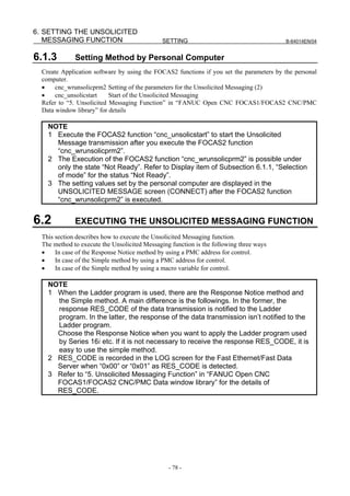
This Subsection describes how to select the mode for setting the Unsolicited Messaging function.
UNSOLICITED MESSAGE screen (BASIC)
Press soft key [UNSOLI MSG] to display the UNSOLICITED MESSAGE screen (BASIC).
UNSOLICITED MESSAGE screen1 (Basic)
Setting item
Item Description
MODE Select the mode for setting the Unsolicited Messaging function.
Refer to the next Operation for the setting method.
For “CNC MODE”:
This mode is for the setting by the CNC screen. In this case, the setting by the personal
computer is impossible. Refer to Subsection 6.1.2, “Setting method by CNC screen” for details.
For “PC MODE”:
This mode is for the setting by the personal computer. In this case, the setting by the CNC
screen is impossible. Refer to Subsection 6.1.3, “Setting method by personal computer” for
details.
NOTE
1 When you use this function for the first time, the mode is “PC MODE”.
2 The change of mode is possible under only the state “Not Ready”. Refer to the
next Display item for the state “Not Ready”.
3 When you change from “CNC MODE” to “PC MODE”, all setting parameters of
the Unsolicited Messaging function are cleared.
Operation
The mode can be changed.
1 Press soft key [(OPRT)] to display soft key [MODE].
- 73 -](https://image.slidesharecdn.com/b-64014en04-121129012902-phpapp02/85/B-64014-en-04-85-320.jpg)
![6. SETTING THE UNSOLICITED
MESSAGING FUNCTION SETTING B-64014EN/04
2 Press soft key [MODE] to display soft keys [CNC MODE] and [PC MODE].
3 Press soft key of the mode that you want to change.
Display item
Item Description
IP ADDRESS The IP address of the connecting personal computer as a Unsolicited Messaging Server is
displayed.
(Example of specification format: "192.168.0.1")
STATUS The Current status is displayed.
The kind of status is the following five states.
[1] Not Ready
The state that data are not transmitted even if there is a data transmission request by NC
program or Ladder program.
[2] Ready
The state that data are transmitted by a data transmission request by NC program or Ladder
program.
[3] Sending…
The state from acceptance of the request until completion of data transmission.
[4] Receiving…
The state from completion of data transmission until receiving the response data.
[5] Completed
The state from receiving the response data until completion of receiving operation.
<Complement>
- The data transmission:
This means that the Unsolicited Message is transferred from the CNC to the personal
computer.
- The response data:
This means that the response of Unsolicited Message is transferred from the personal
computer to the CNC.
NOTE
1 Execute the FOCAS2 function “cnc_unsolicstart” from the personal computer to
change the status from “Not Ready” to “Ready”.
2 Execute the FOCAS2 function “cnc_unsolicstop” from the personal computer to
change the status from except for “Not Ready” to “Not Ready”.
3 Refer to Section 6.2, “EXECUTING THE UNSOLICITED MESSAGING
FUNCTION” for timing charts of status.
6.1.2 Setting Method by CNC Screen
This section describes how to set the parameters by the UNSOLICITED MESSAGE screen.
NOTE
1 Operate the following procedures in order to enable the parameters and start the
Unsolicited Message transmission.
(1) Set all setting items of the UNSOLICITED MESSAGE screen (CONNECT).
(2) Press soft key [(OPRT)] -> [APPLY].
(3) Execute FOCAS2 function “cnc_unsolicstart” to start Unsolicited Messaging
the from the personal computer.
- 74 -](https://image.slidesharecdn.com/b-64014en04-121129012902-phpapp02/85/B-64014-en-04-86-320.jpg)
![6.SETTING THE UNSOLICITED
B-64014EN/04 SETTING MESSAGING FUNCTION
NOTE
2 The input to Setting item and the execution of soft key [(OPRT)] -> [APPLY] in
the UNSOLICITED MESSAGE screen (CONNECT) are possible under only the
state “Not Ready”. Refer to Display item of Subsection 6.1.1, “Selection of mode”
for the status “Not Ready”.
UNSOLICITED MESSAGE screen (CONNECT)
Press soft key [UNSOLI MSG] and page keys to display the UNSOLICITED MESSAGE
screen (CONNECT).
UNSOLICITED MESSAGE screen 2 (CONNECT) UNSOLICITED MESSAGE screen 3 (CONNECT)
Setting item
Item Description
HOST NAME Specify the IP address of the host computer when the DNS function is disabled.
(Example of specification format: "192.168.0.1")
Specify the host name of the host computer when the DNS function is enabled. (You can
specify up to 63 characters.)
(Example of specification format: "UNSOLI-SRV.FACTORY")
PORT NUMBER Specify a TCP port number and a UDP port number. Usually, specify "8196".
Input range: 5001 to 65535
RETRY COUNT Specify the retry count when the server does not respond to the client message.
Input range: 0 to 32767
TIMEOUT Specify the timeout (second) for the response of the transmitted data.
Input range: 1 to 32767
ALIVE TIME Specify the time interval (in seconds) at which to send the alive signal during normal
operation.
Specify the value that is less than TIMEOUT.
Input range: 1 to 32767
- 75 -](https://image.slidesharecdn.com/b-64014en04-121129012902-phpapp02/85/B-64014-en-04-87-320.jpg)
![6.SETTING THE UNSOLICITED
B-64014EN/04 SETTING MESSAGING FUNCTION
CAUTION
1 When setting a PMC address for control and transmission, keep the following in
mind.
(1) For a multi-path PMC, enter a PMC address as follows:
<Path number>:<PMC address>
For R0500 for the second PMC path, for example, enter "2:R500". When only
a PMC address (R500) is entered, it is assumed to be the PMC address for
the first path (1:R0500).
If the ":" key is not provided, the "/" or "EOB" key can be used instead.
(2) The area of a PMC address for control cannot overlap each other area when
other functions (FL-net, PROFIBUS-DP, DeviceNet, and CC-Link) are used.
2 When setting a macro variable for control and transmission, keep the following in
mind.
(1) For a multi-path CNC, enter a macro variable as follows:
<Path number>:<Variable number>
For #100 for the second CNC path, for example, enter "2:100". When only a
variable number (100) is entered, it is assumed to be the variable number for
the first path (1:100).
If the ":" key is not provided, the "/" or "EOB" key can be used instead.
(2) The macro variables for control cannot overlap the variables of use except for
the Unsolicited Messaging function.
NOTE
1 In the methods to specify a PMC address for CONTROL PARAMETER TYPE,
there are the Response Notice method and the Simple method. Refer to Section
6.2, “EXECUTING THE UNSOLICITED MESSAGING” for details.
2 The available range of a PMC address depends on the available PMC Memory
Type.
3 The available range of a custom macro variable and a RTM variable depends on
the valid option.
The RTM variable means a real-time custom macro variable.
No real-time custom macro variable can be used with the Series 35i-B.
4 Set the number of TRANSMISSION PARAMETER (NO.1-3) to TRANSMISSION
NUMBER. For example, when TRANSMISSION NUMBER is “3”, if there are one
or more non-effective value in TRANSMISSION PARAMETER (NO.1-3), an error
occurs by pressing soft key [APPLY].
Operation
The all setting items in UNSOLICITED MESSAGE screen (CONNECT) become effective.
1 Press soft key [(OPRT)] to display soft key [APPLY].
2 Press soft key [APPLY].
- 77 -](https://image.slidesharecdn.com/b-64014en04-121129012902-phpapp02/85/B-64014-en-04-89-320.jpg)
![6.SETTING THE UNSOLICITED
B-64014EN/04 SETTING MESSAGING FUNCTION
6.2.1 When Using a PMC Address for Control (Response Notice
method)
This subsection describes how to use the Response Notice method.
NOTE
Both a PMC address as the control parameter and a macro variable as the
transmission parameter can be set.
In this case, be careful not to clear which timing value to be read if the Ladder
program transmits a macro variable.
The following explanation describes the case that both the control parameter and
the transmission parameter are PMC addresses.
Signals of PMC address for control
This describes the details of the signals of a PMC address for control when the Unsolicited Messaging
function is used. The area of a PMC address for the control is two bytes. The following indicates the case
that “Rxxxx” is used as a PMC address for control. “Rxxxx” means a PMC address that the PMC path
number is omitted
No. #7 #6 #5 #4 #3 #2 #1 #0
Rxxxx REQ
REQ <Rxxxx.7>
[Name] Signal to request the message transmission
[Classification] Input signal
[Function] Requests the Unsolicited Message transmission.
[Operation] Set “1” to this signal after the Ladder program prepares the message. Then the message
will be transmitted to the personal computer.
No. #7 #6 #5 #4 #3 #2 #1 #0
Rxxxx+1 RES COM RES_CODE
RES <Rxxxx+1.7>
[Name] Signal to notify the response of the message
[Classification] Output signal
[Function] This signal indicates that the response of the Unsolicited Message is received.
[Output condition] The response of the message is transmitted from the personal computer to the CNC (the
communication board).
When the CNC (the communication board) receives the response of the message, “1” is
set to this signal. When “1” is set to this signal, the Ladder program reads out the
response code (RES_CODE) and sets “0” to the signal REQ. Then the CNC (the
communication board) will clear RES_CODE and this signal.
COM <Rxxxx+1.6>
[Name] Signal to notify the start of the message transmission
[Classification] Output signal
[Function] This signal indicates that the Unsolicited Message transmission is starting.
[Output condition] When the message transmission to the personal computer is started, “1” is set to this
signal. When the message transmission is completed, “0” is set to this signal.
RES_CODE <Rxxxx+1.0> to <Rxxxx+1.5>
[Name] Indicates the response code of the message
[Classification] Output signal
[Function] This code indicates the response code of the Unsolicited Message.
- 79 -](https://image.slidesharecdn.com/b-64014en04-121129012902-phpapp02/85/B-64014-en-04-91-320.jpg)
![6. SETTING THE UNSOLICITED
MESSAGING FUNCTION SETTING B-64014EN/04
[Output condition] The response code of the message is set. The Ladder program sets “0” to the signal REQ
after reading out this code. Then this code will be cleared by CNC (the communication
board).
NOTE
Refer to “5. Unsolicited Messaging Function” in “FANUC Open
CNC FOCAS1/FOCAS2 CNC/PMC Data window library” for the
details of RES_CODE.
Timing charts of PMC address for control
This describes the timing charts of the signals of a PMC address for control when using the Response
Notice method.
The following example indicates the case that the Unsolicited Message is transmitted only once after the
FOCAS2 function “cnc_unsolicstart” was received, and FOCAS2 function “cnc_unsolicstop” is received.
FOCAS2 function[cnc_unsolicstart] FOCAS2 function[cnc_unsolicstop]
STATUS Not Ready Ready Sending… Receiving… Completed Ready Not Ready
REQ (Ladder -> Board) <1>
<2>
<6>
COM (Board -> Ladder) <3>
RES (Board -> Ladder) <5>
<4>
<7>
RES_CODE (Board -> Ladder)
Ladder : Ladder Program The data transmission The response
Board : Communication Board has been finished becomes available
<1> The Ladder program prepares the message and sets “1” to the signal REQ after its program confirms
that the signal RES has been “0”.
<2> The communication board sets “1” to the COM signal because “1” is set to the signal REQ, and the
message transmission is started.
<3> The communication board sets “0” to the signal COM when the message transmission is completed.
<4> The communication board sets the RES_CODE and sets “1” to the signal RES when the response of
the message is received.
<5> The Ladder program sets “0” to the signal REQ after its program read out the RES_CODE and the
RES signal is “1”.
<6> The communication board clears the RES_CODE because “0” is set to the signal REQ.
<7> The communication board sets “0” to the signal RES.
NOTE
Refer to Display item in Subsection 6.1.1, “Selection of mode” for the details of
STATUS.
- 80 -](https://image.slidesharecdn.com/b-64014en04-121129012902-phpapp02/85/B-64014-en-04-92-320.jpg)
![6.SETTING THE UNSOLICITED
B-64014EN/04 SETTING MESSAGING FUNCTION
6.2.2 When Using a PMC Address for Control (Simple Method)
This subsection describes how to use the Simple method by a PMC address for control.
NOTE
Both a PMC address as the control parameter and a macro variable as the
transmission parameter can be set.
In this case, be careful not to clear which timing value to be read if the Ladder
program transmits a macro variable.
The following explanation describes the case that both the control parameter and
the transmission parameter are PMC addresses.
Signals of PMC address for control
This describes the details of the signals of a PMC address for control to execute the Unsolicited
Messaging function. The area of a PMC address for the control is one byte. The following indicates the
case that “Rxxxx” is used as a PMC address for control. “Rxxxx” means a PMC address that the PMC
path number is omitted
No. #7 #6 #5 #4 #3 #2 #1 #0
Rxxxx REQ
REQ <Rxxxx.7>
[Name] Signal to request the message transmission
[Classification] Input signal/Output signal
[Function] Requests the Unsolicited Message transmission.
[Operation] Set “1” to this signal after the Ladder program prepare the message. Then the message
will be transmitted to the personal computer. When the response of the message is
received, this signal is cleared by CNC (the communication board).
Timing charts of PMC address for control
This describes the timing charts of the signals of a PMC address for control when using the Simple
method.
The following example indicates the case that the Unsolicited Message is transmitted only once after the
FOCAS2 function “cnc_unsolicstart” was received, and FOCAS2 function “cnc_unsolicstop” is received.
FOCAS2 function[cnc_unsolicstart] FOCAS2 function[cnc_unsolicstop]
STATUS Not Ready Ready Sending… Receiving… Completed Ready Not Ready
REQ (Ladder <-> Board) <1>
<2>
<5>
Transmitting operation(Board) <3>
Receiving operation(Board) <4>
Ladder : Ladder Program The data transmission The response is
Board : Communication Board has been finished received
<1> The Ladder program prepares the message and sets “1” to the signal REQ after its program confirms
that the signal REQ has been “0”.
<2> The communication board transmits the message because “1” is set to the signal REQ.
- 81 -](https://image.slidesharecdn.com/b-64014en04-121129012902-phpapp02/85/B-64014-en-04-93-320.jpg)
![6. SETTING THE UNSOLICITED
MESSAGING FUNCTION SETTING B-64014EN/04
<3> The transmitting operation of the communication board is completed.
<4> The receiving operation of the communication board is completed after the response of the message
is received.
<5> The communication board sets “0” to the signal REQ after the receiving operation is completed.
NOTE
1 The REQ signal is also set to “0” when transmission terminates abnormally.
When it is necessary to check the transmission result, use the Response Notice
method described in Subsection 6.2.1.
2 Refer to Display item in Subsection 6.1.1, “Selection of mode” for the details of
STATUS.
6.2.3 When Using a Macro Variable for Control (Simple Method)
This subsection describes how to use the Simple method by a macro variable for control.
The way to use a custom macro variable and a RTM variable in the macro variables for control is the
same.
NOTE
Both a macro variable as the control parameter and a PMC address as the
transmission parameter can be set.
In this case, be careful not to clear which timing value to be read if the NC
program transmits a PMC data.
The following explanation describes the case that both the control parameter and
the transmission parameter are macro variables.
Macro Variables for control
This describes the details of the macro variable for control to execute the Unsolicited Messaging function.
The area of the macro variable for control is one variable. The following indicates the case that “#xxxx”
is used as a macro variable for control. “#xxxx” means a macro variable that the CNC path number is
omitted
REQ <#xxxx>
[Name] Variable to request the message transmission
[Classification] Input variable/Output variable
[Function] Requests the Unsolicited Message transmission.
[Operation] Set “1” to this variable after the NC program prepare the message. Then the message will
be transmitted to the personal computer. When the response of the message received, this
variable is cleared by CNC (the communication board).
NOTE
The input and output value in the variable REQ is a real number. Therefore “0”
and “1” indicate “0.0” and “1.0”.
Timing charts of macro variables for control
This describes the timing charts of the macro variable for control when using the Simple method.
The following example indicates the case that the Unsolicited Message is transmitted only once after the
FOCAS2 function “cnc_unsolicstart” was received, and FOCAS2 function “cnc_unsolicstop” is received.
- 82 -](https://image.slidesharecdn.com/b-64014en04-121129012902-phpapp02/85/B-64014-en-04-94-320.jpg)
![6.SETTING THE UNSOLICITED
B-64014EN/04 SETTING MESSAGING FUNCTION
FOCAS2 function[cnc_unsolicstart] FOCAS2 function[cnc_unsolicstop]
STATUS Not Ready Ready Sending… Receiving… Completed Ready Not Ready
1
REQ (NC <-> Board) 0 <1> <2>
<5>
Transmitting operation(Board) <3>
Receiving operation(Board) <4>
NC : NC Program The data transmission The response is
Board : Communication Board has been finished received
<1> The NC program prepares the message and sets “1” to the variable REQ after its program confirms
that the variable REQ has been “0”.
<2> The communication board transmits the message because “1” is set to the variable REQ.
<3> The transmitting operation of the communication board is completed.
<4> The receiving operation of the communication board is completed after the response of the message
is received.
<5> The communication board sets “0” to the variable REQ after the receiving operation is completed.
NOTE
1 The REQ signal is also set to “0” when transmission terminates abnormally.
When it is necessary to check the transmission result, use the Response Notice
method described in Subsection 6.2.1.
2 Refer to Display item in Subsection 6.1.1, “Selection of mode” for the details of
STATUS.
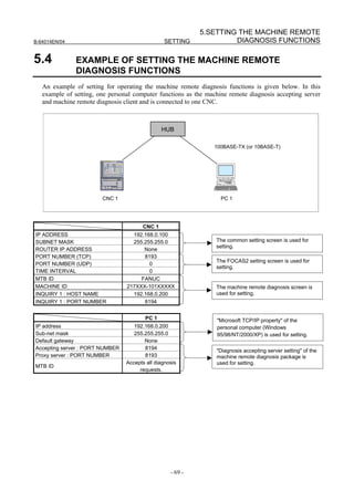
Example to use macro variables for control
This describes the example to use the macro variable for control.
• Example
[Contents]
In the NC program of the CNC path number “1”, the way to transmit the date and time by using
macro variables is explained.
[Setting]
The volatile RTM variable number #0 (REQ) is used as the macro variable for control. And, the
date and time (the system variable number #3011, #3012) managed in the CNC are used as the
macro variable for transmission.
- 83 -](https://image.slidesharecdn.com/b-64014en04-121129012902-phpapp02/85/B-64014-en-04-95-320.jpg)
![6. SETTING THE UNSOLICITED
MESSAGING FUNCTION SETTING B-64014EN/04
Setting item Setting value
CONTROL PARAMETER TYPE 4
CONTROL PARAMETER 1:0
TRANSMISSION NUMBER 2
TRANSMISSION PARAMETER (NO.1)
TYPE 3
MACRO NO. 1:3011
NUMBER 1
TRANSMISSION PARAMETER (NO.2)
TYPE 3
MACRO NO. 1:3012
NUMBER 1
[Example of the NC program]
The RTM executes the next NC command of the RTM at the same time. At this time, the RTM
doesn't influence the operation timing of the next NC command of the RTM.
Therefore, the date and time when the NC command 2 is executed is notified.
RTM for control of the Unsolicited Messaging
//1 ZDO;
ZWHILE[#RV[0] NE 0]; <1>
NC Program #RV[0]=1;
・ ZEND;
・
・
NC Command 1
One cycle of the Macro Call Command
machining program NC Command 2
・
・
・
(Reference) <1> in the example corresponds to <1> in the timing charts above.
NOTE
1 If a custom macro variable is used as the macro variable for control, be careful
to influence the operation timing of the NC command. For example, if the RTM
for control of the above example is replaced to a custom macro, the NC
command 2 isn’t executed unless the macro variable for control changes.
2 Refer to OPERATOR’S MANUAL (Common to Lathe System/Machining Center
System) for the details of a custom macro and a RTM.
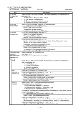
6.3 RELATED NC PARAMETERS
#7 #6 #5 #4 #3 #2 #1 #0
0904 DHC DNS UNM
[Input type] Parameter input
[Data type] Bit
#4 UNM The CNC Unsolicited Messaging function is:
0: Not used.
1: Used.
- 84 -](https://image.slidesharecdn.com/b-64014en04-121129012902-phpapp02/85/B-64014-en-04-96-320.jpg)
![6.SETTING THE UNSOLICITED
B-64014EN/04 SETTING MESSAGING FUNCTION
#5 DNS The DNS function is:
0: Not used.
1: Used.
#6 DHC The DHCP function is:
0: Not used.
1: Used.
NOTE
1 When at least one of these parameters is set, the power must be
turned off before operation is continued.
2 To use the DNS function, set DNS IP ADDRESS 1 and DNS IP
ADDRESS 2 on the COMMON (DETAIL) screen.
#7 #6 #5 #4 #3 #2 #1 #0
0905 UNS
[Input type] Parameter input
[Data type] Bit
#4 UNS In the Unsolicited Messaging function, when the stop request of the Unsolicited
Messaging function is received excluding the connecting Unsolicited Messaging server:
0: The stop request is rejected.
1: The stop request is accepted.
- 85 -](https://image.slidesharecdn.com/b-64014en04-121129012902-phpapp02/85/B-64014-en-04-97-320.jpg)
![7. SETTING THE FTP FILE
TRANSFER FUNCTION SETTING B-64014EN/04
7 SETTING THE FTP FILE TRANSFER
FUNCTION
This chapter describes the setting of parameters for the FTP File Transfer function.
Notes on using the FTP File Transfer function
CAUTION
Before performing FTP communication using the Fast Ethernet for the first time,
consult with your network administrator, carefully set a network address and
other items, and conduct communication tests thoroughly. Any error in settings
such as a network address setting can lead to an adverse influence such as a
communication failure on the entire network.
Be very careful about any communication failure. If the Ethernet is used on a
network involved with a communication failure, a communication failure
intermittently occurs in the Ethernet, which may cause a CNC system error.
NOTE
1 With the FTP File Transfer function (FTP client), a single CNC can connect only
one FTP server.
2 The FTP File Transfer function does not support passive mode (PASV
command).
3 When setting the option (S737) of the Data Server function, the FTP File
Transfer function is unavailable.
7.1 SETTING THE FTP FILE TRANSFER FUNCTION
This section describes the setting screen for operating the FTP File Transfer function.
Procedure
1 Press the function key .
2 Soft key [ETHER BOARD] ([ETHER NET] for the Series 30i/31i/32i/35i-B) appear. (When there is
no soft keys, press the continue key.)
3 Press soft key [ETHER BOARD] to display the Ethernet Setting screen.
4 Press soft keys [COMMON] and [FTP TRANS] and then enter parameters for the items that appear.
- 86 -](https://image.slidesharecdn.com/b-64014en04-121129012902-phpapp02/85/B-64014-en-04-98-320.jpg)
![7.SETTING THE FTP FILE
B-64014EN/04 SETTING TRANSFER FUNCTION
COMMON screen (BASIC)
Press soft key [COMMON] to display the COMMON screen (BASIC).
COMMON screen (BASIC)
Setting item
Item Description
IP ADDRESS Specify the IP address of the Fast Data Server.
(Example of specification format: "192.168.0.100")
SUBNET MASK Specify a mask address for the IP addresses of the network.
(Example of specification format: "255.255.255.0")
ROUTER IP ADDRESS Specify the IP address of the router.
Specify this item when the network contains a router.
(Example of specification format: "192.168.0.253")
Display item
Item Description
MAC ADDRESS Fast Ethernet/Fast Data Server MAC address
NOTE
The second page (detail screen) of the COMMON screen is to be set when the
DNS/DHCP function is used. For details, see "SETTING THE DNS/DHCP
FUNCTION" provided later.
- 87 -](https://image.slidesharecdn.com/b-64014en04-121129012902-phpapp02/85/B-64014-en-04-99-320.jpg)
![7. SETTING THE FTP FILE
TRANSFER FUNCTION SETTING B-64014EN/04
FTP Trans screens (CONNECT1, CONNECT2, CONNECT3)
Press soft key [FTP TRANS] to display the FTP Trans screen.
By using page keys , the three host computers at connection destinations 1, 2, and 3 can be
set.
FTP Trans screens (for connection destination 1)
Setting item
Item Description
HOST NAME Specify the IP address of the host computer.
(Example of specification format: "192.168.0.200")
PORT NUMBER Specify the port number. Usually, set 21 because the FTP communication is used.
USER NAME Specify the name of the user to log on to the host computer using FTP. (A user
name of up to 31 characters can be specified.)
PASSWORD Specify the password for the above user name.
The password must always be specified.
LOGIN FOLDER Specify a work folder to be used when the user logs in to the host computer. (Up to
127 characters can be specified.)
If no data is set, the home folder set on the host computer is used as a login folder.
Operation
Select a connection destination.
1 Press soft key [(OPRT)] to display soft key [HOST SELECT]. Then, press soft key [HOST
SELECT] to display soft keys [CONECT 1], [CONECT 2], and [CONECT 3].
- 88 -](https://image.slidesharecdn.com/b-64014en04-121129012902-phpapp02/85/B-64014-en-04-100-320.jpg)
![7.SETTING THE FTP FILE
B-64014EN/04 SETTING TRANSFER FUNCTION
2 Press one of soft keys [CONECT 1], [CONECT 2], and [CONECT 3] according to the host
computer to which you want to make a connection. The screen title of connection destination 1, 2 or
3 is displayed in reverse video. The screen title displayed in reverse video indicates the connection
destination host computer.
When connection destination 1 is selected
7.2 RELATED NC PARAMETERS
The NC parameters related to the FTP File Transfer function are described below.
0020 I/O CHANNEL : Input/output device selection
[Input type] Setting input
[Data type] Byte
[Valid data range] 5 : Selects the FTP File transfer function as the input/output device.
#7 #6 #5 #4 #3 #2 #1 #0
0901 EFT
[Input type] Parameter input
[Data type] Bit
#1 EFT The FTP file transfer function by the Fast Ethernet board is:
0: Not used.
1: Used.
NOTE
1 When this parameter is set, the power must be turned off before
operation is continued.
2 This parameter is valid only for Path 1.
3 If Data Server function is valid, FTP File Transfer function cannot
be used.
#7 #6 #5 #4 #3 #2 #1 #0
0905 PCH
[Input type] Parameter input
[Data type] Bit
#1 PCH At the start of communication of the Data Server, FTP file transfer function, or machine
remote diagnosis functions, checking for the presence of the server using PING is:
0: Performed.
1: Not performed.
NOTE
Usually, set Performed (0).
When the presence of the server using PING is not checked by
setting 1, it may take several tens of seconds until an error is
recognized due to no server on the network.
For mainly security reasons, a personal computer may be set so
that it does not respond to the PING command. Set 1 when the
Data Server communicates with such a personal computer.
- 89 -](https://image.slidesharecdn.com/b-64014en04-121129012902-phpapp02/85/B-64014-en-04-101-320.jpg)
![7. SETTING THE FTP FILE
TRANSFER FUNCTION SETTING B-64014EN/04
0921 Selects the host computer 1 OS.
0922 Selects the host computer 2 OS.
0923 Selects the host computer 3 OS.
[Input type] Parameter input
[Data type] Word
[Valid data range] 0 to 2
0: Windows95/98/Me/NT/2000/XP/Vista/7.
1: UNIX/VMS.
2: Linux.
NOTE
Some FTP server software may not depend on the OS. Therefore,
the valid file list may not be displayed by the above setting.
- 90 -](https://image.slidesharecdn.com/b-64014en04-121129012902-phpapp02/85/B-64014-en-04-102-320.jpg)
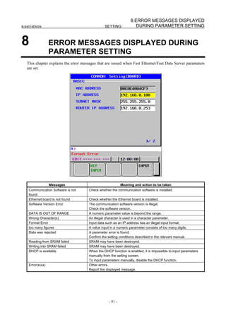


![1.OPERATING THE DATA SERVER
B-64014EN/04 OPERATION FUNCTIONS
1 OPERATING THE DATA SERVER
FUNCTIONS
This chapter describes how to operate the Data Server functions.
On the PROGRAM FOLDER screen, files on the CNC memory, memory card, host computer connected
via the embedded Ethernet, memory card built into the Fast Data Server, or host computer connected via
the Fast Data Server can be handled by selecting a device.
Series 30i/31i/32i-A/B
CNC memory
Memory card
Via embedded
Ethernet
File list
FAST Data Server
Memory card
PROGRAM FOLDER screen Via FAST Data Server
File list
In this chapter, the method of handling files on the memory card built into the Fast Data Server and on the
host computer connected via the Fast Data Server is described.
1.1 DEVICE CHANGE ON THE PROGRAM FOLDER SCREEN
Procedure
1 Press the function key .
2 Press soft key [FOLDER] to display the PROGRAM FOLDER screen. (When there is no soft keys,
press the continue key.)
- 95 -](https://image.slidesharecdn.com/b-64014en04-121129012902-phpapp02/85/B-64014-en-04-107-320.jpg)
![1. OPERATING THE DATA SERVER
FUNCTIONS OPERATION B-64014EN/04
PROGRAM FOLDER screen
3 Press soft key [(OPRT)] then soft key [DEVICE CHANGE] to display the soft keys for selectable
devices.
4 When you press soft key [DTSVR], the information displayed on the PROGRAM FOLDER screen
is changed to the contents (DATA SERVER FILE LIST screen) of the memory card built into the
Fast Data Server to enable file operation.
5 When you press soft key [DTSVR HOST], the information displayed on the PROGRAM FOLDER
screen is changed to the contents (DATA SERVER HOST FILE LIST screen) of the hard disk of the
host computer to enable file operation.
1.2 OPERATING THE DATA SERVER FILE LIST SCREEN
If [DTSVR] is selected to change the device on the PROGRAM FOLDER screen, the contents (DATA
SERVER FILE LIST screen) of the memory card built into the Fast Data Server are displayed to enable
file operation.
The information displayed on the DATA SERVER FILE LIST screen partly changes, depending on the
setting of bit 1 (PDM) of NC parameter No. 3233.
When bit 1 (PDM) of parameter No. 3233 is set to 0, an M198 operation folder and DNC operation file
can be set.
When bit 1 (PDM) of parameter No. 3233 is set to 1, foreground/background folders can be set.
- 96 -](https://image.slidesharecdn.com/b-64014en04-121129012902-phpapp02/85/B-64014-en-04-108-320.jpg)
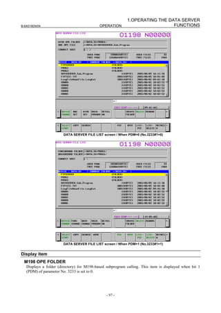
![1. OPERATING THE DATA SERVER
FUNCTIONS OPERATION B-64014EN/04
DNC OPE FILE
Displays a file name used when DNC operation is performed. This item is displayed when bit 1 (PDM) of
parameter No. 3233 is set to 0.
FOREGROUND FOLDER / BACKGROUND FOLDER
Displays foreground/background folders (directories). This item is displayed when bit 1 (PDM) of
parameter No. 3233 is set to 1.
CONNECT HOST
Displays the work folder and the number of the host currently connected.
USED PAGE / FREE PAGE
Displays the size used of the memory card built into the Fast Data Server and the size that is free.
USED FILES / FREE FILES
Displays the total number of folders (files) in use of the Data Server and the number of remaining free
folders (files).
DEVICE
Displays the current device. If the memory card built into the Fast Data Server is selected, "DATA_SV"
is indicated.
CURRENT FOLDER
Displays the current work folder.
File list
Displays information about the files and folders in the current work folder.
Operation list
DEVICE CHANGE
Enables a device for display on the PROGRAM FOLDER screen. When selecting the memory card built
into the Fast Data Server, press soft key [DTSVR].
DNC SET
Specifies a file for DNC operation. This soft key can be used when bit 1 (PDM) of parameter No. 3233 is
set to 0.
M198 SET
Specifies a folder for M198-based subprogram calling. This soft key can be used when bit 1 (PDM) of
parameter No. 3233 is set to 0.
FORE CHANGE / BACK CHNAGE
Specifies a foreground/background folder. These soft keys can be used when bit 1 (PDM) of parameter
No. 3233 is set to 1.
MAIN PROGRM
Selects a file as a main program.
DETAIL OFF / DETAIL ON
Switches the file list information to overall display or detail display.
- 98 -](https://image.slidesharecdn.com/b-64014en04-121129012902-phpapp02/85/B-64014-en-04-110-320.jpg)
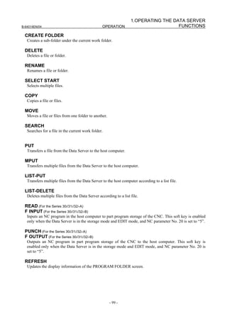
![1. OPERATING THE DATA SERVER
FUNCTIONS OPERATION B-64014EN/04
NOTE
The operations of soft keys [CREATE FOLDER], [DELETE], [RENAME],
[COPY], [MOVE], and [LIST-DELETE] are the target operations of the memory
protection key.
This means that when the memory protection key is enabled, these operations
result in a "WRITE PROTECT" error and cannot be performed.
For information about the memory protection key, refer to the CONNECTION
MANUAL (FUNCTION) of the CNC.
1.2.1 Displaying and Operating the File List
REFRESH, DETAIL OFF, DETAIL ON
The contents of the file list can be updated and displayed.
1 Press soft key [REFRESH] to update the contents of the file list.
2 Press soft key [DETAIL OFF] to display a file name, size, and date.
3 Press soft key [DETAIL ON] to display a file list with file attributes and comments. A comment
statement immediately following the O number of a file is displayed. When there is no comment
statement, the contents starting with the beginning of the file are displayed.
NOTE
1 For a file selected as a main program and a file being used for memory
operation, no comment is displayed in detail display mode.
2 The file attribute of a binary file is displayed as "R/B" to the right of the comment.
MOVE FOLDER
A work folder can be moved.
1 By using cursor keys , select a folder to be moved.
2 Press the MDI key .
CREATE FOLDER
A new folder can be created.
1 Move to a new folder to be created.
2 Enter a desired folder name.
3 Press soft key [CREATE FOLDER].
NOTE
1 Up to six levels of folders can be created.
2 No duplicate folder name is allowed within the same folder.
3 Each time a folder is created, the number of programs that can be registered
decreases by one.
4 No folder may be able to be created, depending on the status such as operation
state or protection state.
- 100 -](https://image.slidesharecdn.com/b-64014en04-121129012902-phpapp02/85/B-64014-en-04-112-320.jpg)
![1.OPERATING THE DATA SERVER
B-64014EN/04 OPERATION FUNCTIONS
DELETE
Specifying a file or folder
A file or folder can be deleted.
1 By using cursor keys , select a file or folder to be deleted.
2 Press soft key [DELETE].
- Press soft key [EXEC] for execution.
- Press soft key [CANCEL] for cancellation.
NOTE
1 The initial folder cannot be deleted.
2 A folder can be deleted only when the folder is empty.
(An empty folder means a folder that does not contain any folder and file.)
3 Files or folders may not be able to be deleted, depending on the status such as
operation state or protection state.
Specifying multiple files
Multiple files can be deleted at a time.
1 Press soft key [SELECT START].
2 By using cursor keys , select a file to be deleted.
3 Press soft key [SELECT].
A selected file is displayed in reverse video.
Repeat steps 2 and 3 for files to be deleted.
4 Press soft key [DELETE].
• Press soft key [EXEC] for execution.
• Press soft key [CANCEL] for cancellation.
NOTE
1 No folder can be specified.
2 Files may not be able to be deleted, depending on the status such as operation
state or protection state.
3 Up to 10 files can be selected at a time.
DELETE (new specification)
Specifying a file or folder
A file or folder can be deleted.
1 Place the cursor on the name of a file or folder to be deleted.
2 Press soft key [DELETE].
• Press soft key [EXEC] for execution.
• Press soft key [CANCEL] for cancellation.
Selecting a range
Multiple files or folders can be deleted.
1 Press soft key [SELECT].
2 Place the cursor on the name of a file to be deleted and press soft key [RANGE SELECT].
- 101 -](https://image.slidesharecdn.com/b-64014en04-121129012902-phpapp02/85/B-64014-en-04-113-320.jpg)
![1. OPERATING THE DATA SERVER
FUNCTIONS OPERATION B-64014EN/04
3 By using cursor keys , select a range of files to be deleted.
A selected file is displayed in reverse video.
4 When you have selected a desired range, press soft key [DELETE].
• Press soft key [EXEC] for execution.
• Press soft key [CANCEL] for cancellation.
Selecting individual files or folders
Multiple files or folders can be deleted.
1 Press soft key [SELECT].
2 Place the cursor on the name of a file to be deleted and press soft key [SELECT].
A selected file is displayed in reverse video.
3 Repeat step 2 for all files to be selected.
4 When you have selected desired files, press soft key [DELETE].
• Press soft key [EXEC] for execution.
• Press soft key [CANCEL] for cancellation.
NOTE
1 Delete operation of the new specification is performed when bit 3 (PCP) of
parameter No. 11374 is set to 1 for the Series 30i/31i/32i-A or bit 4 (PCB) of
parameter No. 11374 is set to 0 for the Series 30i/31i/32i-B.
2 The initial folder cannot be deleted.
3 Folders can also be specified and deleted only when the folders are empty.
(An empty folder means a folder that does not contain any folder and file.)
4 Files or folders may not be able to be deleted, depending on the status such as
operation state or protection state.
5 Up to 10 files can be selected at a time.
RENAME
A file or folder can be renamed.
1 By using cursor keys , select a file or folder to be renamed.
2 Key a new file name or folder name.
3 Press soft key [RENAME].
NOTE
1 The initial folder cannot be renamed.
2 No duplicate folder name is allowed within the same folder.
3 Files and folders may not be able to be renamed, depending on the status such
as operation state or protection state.
SEARCH
In the current work folder, a file can be found.
1 Enter a desired file name.
2 Press soft key [SEARCH].
- 102 -](https://image.slidesharecdn.com/b-64014en04-121129012902-phpapp02/85/B-64014-en-04-114-320.jpg)
![1.OPERATING THE DATA SERVER
B-64014EN/04 OPERATION FUNCTIONS
COPY
Only one file
A file can be copied within the same folder.
1 Place the CNC in the EDIT mode.
2 By using cursor keys , select a copy source file.
3 Key the name of a copy destination file.
4 Press soft key [COPY].
NOTE
1 Copy operation is impossible if the same file name is specified as a copy source
file and copy destination file.
2 No folder can be specified.
3 Files may not be able to be copied, depending on the status such as operation
state or protection state.
Selecting individual files or folders
Multiple files can be copied.
1 Place the CNC in the EDIT mode.
2 Press soft key [SELECT START].
3 By using cursor keys , select a copy source file.
4 Press soft key [SELECT].
A selected file is displayed in reverse video.
Repeat steps 2 and 3 for files to be copied.
5 Press soft key [SELECT END].
6 Move to a copy destination folder.
7 Press soft key [COPY].
NOTE
1 Copy operation is impossible if the same folder is specified as a copy source
folder and copy destination folder.
2 No folder can be specified.
3 Files may not be able to be copied, depending on the status such as operation
state or protection state.
4 Up to 10 files can be selected at a time.
COPY (new specification)
Only one file
One file can be copied.
1 Place the cursor on the name of a file to be copied and press soft key [COPY].
A selected file is displayed in reverse video.
2 Move to a copy destination folder.
3 Press soft key [PASTE].
To rename and copy the file, enter the new file name in the key-in buffer and press soft key
[PASTE].
- 103 -](https://image.slidesharecdn.com/b-64014en04-121129012902-phpapp02/85/B-64014-en-04-115-320.jpg)
![1. OPERATING THE DATA SERVER
FUNCTIONS OPERATION B-64014EN/04
Selecting a range
Multiple files can be copied.
1 Press soft key [SELECT].
2 Place the cursor on the name of a file to be copied and press soft key [RANGE SELECT].
3 By using cursor keys , select a range of files to be copied.
A selected file is displayed in reverse video.
4 When you have selected a desired range, press soft key [COPY].
5 Move to a copy destination folder.
6 Press soft key [PASTE].
Selecting individual files or folders
Multiple files can be copied.
1 Press soft key [SELECT].
2 Place the cursor on the name of a file to be copied and press soft key [SELECT].
A selected file is displayed in reverse video.
3 Repeat step 2 for all files to be selected.
4 When you have selected desired files, press soft key [COPY].
5 Move to a copy destination folder.
6 Press soft key [PASTE].
NOTE
1 Copy operation of the new specification is performed when bit 3 (PCP) of
parameter No. 11374 is set to 1 for the Series 30i/31i/32i-A or bit 4 (PCB) of
parameter No. 11374 is set to 0 for the Series 30i/31i/32i-B.
2 With copy operation of the new specification, not only a file or files, but also a
folder or folders can be selected. In this case, all files in the selected folder(s)
are copied.
3 Copy operation is impossible if the same folder is specified as a copy source
folder and copy destination folder.
4 Files or folders may not be able to be copied, depending on the status such as
operation state or protection state.
5 Up to 10 files can be selected at a time.
MOVE
A file or files can be moved.
1 Place the CNC in the EDIT mode.
2 Press soft key [SELECT START].
3 By using cursor keys , select a move source file.
4 Press soft key [SELECT].
A selected file is displayed in reverse video.
Repeat steps 2 and 3 for files to be moved.
5 Press soft key [SELECT END].
6 Move to a move destination folder.
7 Press soft key [MOVE].
- 104 -](https://image.slidesharecdn.com/b-64014en04-121129012902-phpapp02/85/B-64014-en-04-116-320.jpg)
![1.OPERATING THE DATA SERVER
B-64014EN/04 OPERATION FUNCTIONS
NOTE
1 Move operation is impossible if the same folder is specified as a move source
folder and move destination folder.
2 No folder can be specified.
3 Files may not be able to be moved, depending on the status such as operation
state or protection state.
4 Up to 10 files can be selected at a time.
MOVE (new specification)
Only one file
One file can be moved.
1 Place the cursor on the name of a file to be moved and press soft key [CUT].
A selected file is displayed in reverse video.
2 Move to a move destination folder.
3 Press soft key [PASTE].
To rename and move the file, enter the new file name in the key-in buffer and press soft key
[PASTE].
Selecting a range
Multiple files can be moved.
1 Press soft key [SELECT].
2 Place the cursor on the name of a file to be moved and press soft key [RANGE SELECTT].
3 By using cursor keys , select a range of files to be moved.
A selected file is displayed in reverse video.
4 When you have selected a desired range, press soft key [CUT].
5 Move to a move destination folder.
6 Press soft key [PASTE].
Selecting individual files or folders
Multiple files can be moved.
1 Press soft key [SELECT].
2 Place the cursor on the name of a file to be moved and press soft key [SELECTT].
A selected file is displayed in reverse video.
3 Repeat step 2 for all files to be selected.
4 When you have selected desired files, press soft key [CUT].
5 Move to a move destination folder.
6 Press soft key [PASTE].
NOTE
1 Move operation of the new specification is performed when bit 3 (PCP) of
parameter No. 11374 is set to 1 for the Series 30i/31i/32i-A or bit 4 (PCB) of
parameter No. 11374 is set to 0 for the Series 30i/31i/32i-B.
2 With move operation of the new specification, not only a file or files, but also a
folder or folders can be selected. In this case, all files in the selected folder(s)
are moved.
3 Move operation is impossible if the same folder is specified as a move source
folder and move destination folder.
- 105 -](https://image.slidesharecdn.com/b-64014en04-121129012902-phpapp02/85/B-64014-en-04-117-320.jpg)
![1. OPERATING THE DATA SERVER
FUNCTIONS OPERATION B-64014EN/04
NOTE
4 Files or folders may not be able to be moved, depending on the status such as
operation state or protection state.
5 Up to 10 files can be selected at a time.
LIST-DELETE
By using a list file, multiple files in the Data Server can be deleted.
1 By using cursor keys , select a list file.
2 Press soft key [LIST-DELETE].
• Press soft key [EXEC] for execution.
• Press soft key [CANCEL] for cancellation.
When execution is selected, the files in the Data Server are deleted according to the list file.
NOTE
Files cannot sometimes be deleted depending on the operation status and
protection status.
1.2.2 File Transfer Operation
Files can be transferred from the Data Server to the host computer.
NOTE
If an error occurs, check the cause of the error according to the Item,
“ETHERNET LOG screen” in Section 2.1, ”ETHERNET LOG” in Part VI,
“MAINTENANCE.”
PUT
A file can be transferred from the Data Server to the host computer.
1 By using cursor keys , select a file to be transferred.
2 Press soft key [PUT].
• Press soft key [EXEC] for execution.
• Press soft key [CANCEL] for cancellation.
3 When a file is to be transferred to the host computer under a different file name, enter the desired
transfer destination file name before pressing soft key [PUT].
MPUT
Multiple files can be transferred from the Data Server to the host computer.
1 Enter the names of files to be transferred. Specify the names of files using wildcards (*, ?).
2 Press soft key [MPUT].
• Press soft key [EXEC] for execution.
• Press soft key [CANCEL] for cancellation.
- 106 -](https://image.slidesharecdn.com/b-64014en04-121129012902-phpapp02/85/B-64014-en-04-118-320.jpg)
![1.OPERATING THE DATA SERVER
B-64014EN/04 OPERATION FUNCTIONS
LIST-PUT
Multiple files can be transferred from the Data Server to the host computer according to a list file.
1 By using cursor keys , select a list file.
2 Press soft key [LIST-PUT].
• Press soft key [EXEC] for execution.
• Press soft key [CANCEL] for cancellation.
When execution is selected, the files are transferred from the Data Server to the host computer
according to the list file.
1.2.3 Preparations for File Operation and Editing
MAIN PROGRM
A selected file can be registered as a main program.
1 Select the EDIT mode or MEM mode.
2 By using cursor keys , select a file to be registered as a main program.
3 Press soft key [MAIN PROGRM].
A registered main program can be executed in memory operation or edited.
NOTE
1 No file may be able to be selected, depending on the status such as operation
state or protection state.
2 Only a text file can be selected as a main program.
3 For a file selected as a main program and a file being used for memory
operation, no comment is displayed in detail display mode.
4 For a file selected as a main program, other file operations are disabled.
5 For memory operation and editing, refer to the OPERATOR’S MANUAL of the
CNC.
M198 SET
A folder for M198-based subprogram calling can be specified.
1 Move to the folder containing a file to be called by M198-based subprogram calling.
2 Press soft key [M198 SET].
NOTE
1 No file may be able to be set, depending on the status such as operation state or
protection state.
2 This setting is valid when the operating mode of the Data Server is the storage
mode.
3 The specified folder name is stored and can be used without specifying it at the
next power-on.
- 107 -](https://image.slidesharecdn.com/b-64014en04-121129012902-phpapp02/85/B-64014-en-04-119-320.jpg)
![1. OPERATING THE DATA SERVER
FUNCTIONS OPERATION B-64014EN/04
DNC SET
A file used for DNC operation can be selected.
1 Move to the folder containing a file to be used for DNC operation.
2 By using cursor keys , select a file to be used for DNC operation.
3 Press soft key [DNC SET].
NOTE
1 No file may be able to be set, depending on the status such as operation state or
protection state.
2 This setting is valid when the operating mode of the Data Server is the storage
mode.
3 The specified file name is not stored. Accordingly, specify a file again after
turning the power off, then on again.
FORE CHANGE / BACK CHANGE
A foreground/background folder can be specified.
1 Move to the folder containing a foreground/background file.
2 Press soft key [FORE CHANGE] or [BACK CHANGE].
1.3 OPERATING THE DATA SERVER HOST FILE LIST
SCREEN
Host computer files can be operated on the DATA SERVER HOST FILE LIST screen.
DATA SERVER HOST FILE LIST screen
- 108 -](https://image.slidesharecdn.com/b-64014en04-121129012902-phpapp02/85/B-64014-en-04-120-320.jpg)
![1.OPERATING THE DATA SERVER
B-64014EN/04 OPERATION FUNCTIONS
NOTE
A file name containing a 2-byte code used for Japanese and others may not be
displayed correctly.
Display item
M198 OPE FOLDER
Displays a folder (directory) for M198-based subprogram calling.
DNC OPE FILE
Displays a file name used when DNC operation is performed.
DT SERVER FOLDER
Displays the work folder (directory) of the Data Server (memory card).
CONNECT HOST
Displays the number of the host computer currently connected.
DEVICE
Displays the current device. If the host file list of the Data Server is selected, "DTSVR_HOST" is
indicated.
CURRENT FOLDER
Displays the work folder in the current host computer.
FILE LIST
Displays information about the files and folders in the host computer.
Operation list
DEVICE CHANGE
Enables a device for display on the PROGRAM FOLDER screen. When selecting the host file list of the
Data Server, press soft key [DTSVR HOST].
DNC SET
Specifies a file for DNC operation.
M198 SET
Specifies a folder for M198-based subprogram calling.
DETAIL OFF / DETAIL ON
Switches the file list information to overall display or detail display.
CREATE FOLDER
Creates a sub-folder under the current work folder.
DELETE
Deletes a file or folder.
RENAME
Renames a file or folder.
- 109 -](https://image.slidesharecdn.com/b-64014en04-121129012902-phpapp02/85/B-64014-en-04-121-320.jpg)
![1. OPERATING THE DATA SERVER
FUNCTIONS OPERATION B-64014EN/04
HOST CHANGE
Changes the connected host computer.
SEARCH
Searches for a file in the current folder.
GET
Transfers a file from the host computer to the Data Server.
MGET
Transfers files from the host computer to the Data Server by specifying a file name with wildcards (*, ?).
BGET
Transfers a file from the host computer to the Data Server in binary format. Use this soft key to transfer a
binary-format NC program or data other than an NC program such as NC parameter or tool data.
LIST-GET
Transfers multiple files from the host computer to the Data Server according to a list file.
READ (For the Series 30i/31i/32i-A)
F INPUT (For the Series 30i/31i/32i-B)
Inputs an NC program in the host computer to part program storage of the CNC. This soft key is enabled
only when the Data Server is in the FTP mode and EDIT mode, and NC parameter No. 20 is set to “5”.
PUNCH (For the Series 30i/31i/32i-A)
F OUTPUT (For the Series 30i/31i/32i-B)
Outputs an NC program in part program storage of the CNC to the host computer. This soft key is
enabled only when the Data Server is in the FTP mode and EDIT mode, and NC parameter No. 20 is set
to “5”.
REFRESH
Updates the information displayed on the DATA SERVER HOST FILE LIST screen.
NOTE
The operations of soft keys [GET], [MGET], [BGET], and [LIST-GET] are the
target operations of the memory protection key.
This means that when the memory protection key is enabled, these operations
result in a "WRITE PROTECT" error and cannot be performed.
For information about the memory protection key, refer to the CONNECTION
MANUAL (FUNCTION) (B-63943EN-1) of the CNC.
1.3.1 Displaying and Operating the File List
RENAME, DETAIL OFF, DETAIL ON
The contents of the file list can be updated and displayed.
1 Press soft key [REFRESH] to update the contents of the file list.
2 Press soft key [DETAIL OFF] to display a file name only.
3 Press soft key [DETAIL ON] to display a file attribute, size, date, and file name.
- 110 -](https://image.slidesharecdn.com/b-64014en04-121129012902-phpapp02/85/B-64014-en-04-122-320.jpg)
![1.OPERATING THE DATA SERVER
B-64014EN/04 OPERATION FUNCTIONS
NOTE
1 The information displayed with soft key [DETAIL ON] depends on the setting of
the FTP server on the host computer.
2 When a file operation is performed in the detail display mode, the rightmost
information displayed on the screen is handled as the file name. For this reason,
the file operation may not be performed correctly depending on the displayed
information or file name. In this case, set the overall display mode and perform
the file operation.
MOVE FOLDER
A work folder can be moved.
1 By using cursor keys , select a folder to be moved.
2 Press the MDI key .
CREATE FOLDER
A new folder can be created.
1 Move to a new folder to be created.
2 Enter a desired folder name.
3 Press soft key [CREATE FOLDER].
DELETE
Specifying a file or folder
A file or folder can be deleted.
1 By using cursor keys , select a file or folder to be deleted.
2 Press soft key [DELETE].
• Press soft key [EXEC] for execution.
• Press soft key [CANCEL] for cancellation.
Specifying multiple files
Multiple files or folder can be deleted.
1 Press soft key [SELECT START].
2 By using cursor keys , select a file to be deleted.
3 Press soft key [SELECT].
A selected file is displayed in reverse video.
Repeat steps 2 and 3 for files to be deleted.
4 Press soft key [DELETE].
• Press soft key [EXEC] for execution.
• Press soft key [CANCEL] for cancellation.
NOTE
Up to 10 files can be selected at a time.
- 111 -](https://image.slidesharecdn.com/b-64014en04-121129012902-phpapp02/85/B-64014-en-04-123-320.jpg)
![1. OPERATING THE DATA SERVER
FUNCTIONS OPERATION B-64014EN/04
DELETE (new specification)
Specifying a file or folder
A file or folder can be deleted.
1 Place the cursor on the name of a file or folder to be deleted.
2 Press soft key [DELETE].
• Press soft key [EXEC] for execution.
• Press soft key [CANCEL] for cancellation.
Selecting a range
Multiple files or folders can be deleted.
1 Press soft key [SELECT].
2 Place the cursor on the name of a file to be deleted and press soft key [RANGE SELECT].
3 By using cursor keys , select a range of files to be deleted.
A selected file is displayed in reverse video.
4 When you have selected a desired range, press soft key [DELETE].
• Press soft key [EXEC] for execution.
• Press soft key [CANCEL] for cancellation.
Selecting individual files or folders
Multiple files or folders can be deleted.
1 Press soft key [SELECT].
2 Place the cursor on the name of a file to be deleted and press soft key [SELECT].
A selected file is displayed in reverse video.
3 Repeat step 2 for all files to be selected.
4 When you have selected desired files, press soft key [DELETE].
• Press soft key [EXEC] for execution.
• Press soft key [CANCEL] for cancellation.
NOTE
1 Delete operation of the new specification is performed when bit 3 (PCP) of
parameter No. 11374 is set to 1 for the Series 30i/31i/32i-A or bit 4 (PCB) of
parameter No. 11374 is set to 0 for the Series 30i/31i/32i-B.
2 Up to 10 files can be selected at a time.
RENAME
A file or folder can be renamed.
1 By using cursor keys , select a file or folder to be renamed.
2 Key a new file name or folder name.
3 Press soft key [RENAME].
SEARCH
In the current work folder, a file can be found.
1 Enter a desired file name.
2 Press soft key [SEARCH],
- 112 -](https://image.slidesharecdn.com/b-64014en04-121129012902-phpapp02/85/B-64014-en-04-124-320.jpg)
![1.OPERATING THE DATA SERVER
B-64014EN/04 OPERATION FUNCTIONS
HOST CHANGE
The connected host computer can be changed.
1 Press soft key [HOST CHANGE].
The connected host number changes in the order 1 → 2 → 3 → 1.
1.3.2 File Transfer Operation
Files can be transferred from the host computer to the Data Server.
NOTE
If an error occurs, check the cause of the error according to the Item,
“ETHERNET LOG screen” in Section 2.1, ”ETHERNET LOG” in Part VI,
“MAINTENANCE.”
GET
An NC program can be transferred from the host computer to the Data Server.
1 By using cursor keys , select a file to be transferred.
2 Press soft key [GET].
• Press soft key [EXEC] for execution.
• Press soft key [CANCEL] for cancellation.
3 When a file is to be transferred to the Data Server under a different file name, enter the desired
transfer destination file name before pressing soft key [GET].
NOTE
1 Files cannot sometimes be transferred depending on the operation status and
protection status.
2 Use this operation only for text format NC programs.
MGET
Multiple NC programs can be transferred from the host computer to the Data Server.
1 Enter the names of files to be transferred. Specify the names of files using wildcards (*, ?).
2 Press soft key [MGET].
• Press soft key [EXEC] for execution.
• Press soft key [CANCEL] for cancellation.
NOTE
1 Files cannot sometimes be transferred depending on the operation status and
protection status.
2 Use this operation only for text format NC programs.
- 113 -](https://image.slidesharecdn.com/b-64014en04-121129012902-phpapp02/85/B-64014-en-04-125-320.jpg)
![1. OPERATING THE DATA SERVER
FUNCTIONS OPERATION B-64014EN/04
BGET
A file can be transferred from the host computer to the Data Server.
1 By using cursor keys , select a file to be transferred.
2 Press soft key [BGET].
• Press soft key [EXEC] for execution.
• Press soft key [CANCEL] for cancellation.
3 When a file is to be transferred to the Data Server under a different file name, enter the desired
transfer destination file name before pressing soft key [BGET].
NOTE
1 Files cannot sometimes be transferred depending on the operation status and
protection status.
2 When transferring binary format NC programs and NC data such as tool offset
data, be sure to use the binary format.
LIST-GET
Multiple files can be transferred from the host computer to the Data Server according to a list file.
1 By using cursor keys , select a list file.
2 Press soft key [LIST-GET].
• Press soft key [EXEC] for execution.
• Press soft key [CANCEL] for cancellation.
When execution is selected, the files are transferred from the host computer to the Data Server according
to the list file.
NOTE
Files cannot sometimes be transferred depending on the operation status and
protection status.
1.3.3 Preparations for File Operation
M198 OPE
A folder for M198-based subprogram calling can be specified.
1 Move to the folder containing a file to be called by M198-based subprogram calling.
2 Press soft key [M198 SET].
NOTE
1 No file may be able to be set, depending on the status such as operation state or
protection state.
2 This setting is valid when the operating mode of the Data Server is the FTP
mode or buffer mode.
3 The specified folder name is stored and can be used without specifying it at the
next power-on.
- 114 -](https://image.slidesharecdn.com/b-64014en04-121129012902-phpapp02/85/B-64014-en-04-126-320.jpg)
![1.OPERATING THE DATA SERVER
B-64014EN/04 OPERATION FUNCTIONS
DNC OPE
A file used for DNC operation can be selected.
1 Move to the folder containing a file to be used for DNC operation.
2 By using cursor keys , select a file to be used for DNC operation.
3 Press soft key [DNC SET].
NOTE
1 No file may be able to be set, depending on the status such as operation state or
protection state.
2 This setting is valid when the operating mode of the Data Server is the FTP
mode or buffer mode.
3 The specified file name is not stored. Accordingly, specify a file again after
turning the power off, then on again.
1.4 M198-BASED SUBPROGRAM CALL
If the Data Server is placed in the storage mode, an M198-based subprogram call can be made using an
NC program in the Data Server.
If the Data Server is placed in the FTP mode, an M198-based subprogram call can be made using an NC
program in the host computer. If the Data Server is placed in the buffer mode, an M198-based
subprogram call can be made using an NC program of the buffer mode format in the host computer.
NOTE
1 An M198-based subprogram call cannot be executed simultaneously with NC
program input, NC program output, and DNC operation.
2 In an M198-based subprogram call, no additional M198-baesd subprogram call
can be made.
3 M198-based subprogram calls do not allow use of file names. Use a program
number to make an M198-based call.
Subprogram call in the storage mode
Procedure
1 Check that the Data Server is placed in the storage mode.
2 Set the CNC to the MEM mode.
3 Display the DATA SERVER FILE LIST screen to check that an M198 operation folder is set.
4 Automatically operate the NC program including the M198 command.
Subprogram call in the FTP mode
Procedure
1 Check that the Data Server is placed in the FTP mode.
2 Set the CNC to the MEM mode.
3 Display the DATA SERVER HOST FILE LIST screen to check that an M198 operation folder is set.
4 Automatically operate the NC program including the M198 command.
- 115 -](https://image.slidesharecdn.com/b-64014en04-121129012902-phpapp02/85/B-64014-en-04-127-320.jpg)
![1.OPERATING THE DATA SERVER
B-64014EN/04 OPERATION FUNCTIONS
CAUTION
If bit 2 of NC parameter No. 3201 is set to 1, when an NC program having the
same file name as an NC program to be input is already present in part program
storage, the existing NC program is overwritten.
NOTE
NC programs cannot be input simultaneously with an NC program output,
M198-based subprogram call, and DNC operation.
Procedure
1 Place the CNC in the EDIT mode.
2 Display the PROGRAM screen or PROGRAM FOLDER screen.
3 Press soft key [READ] ([F INPUT] for the Series 30i/31i/32i/35i-B).
4 In the key-in buffer, enter the name of a file to be input on the Data Server, and press soft key [F
SET].
When the file name on the Data Server is not set, file name "ALL-PROG.TXT" is used by default.
5 To rename the input file and input it into part program storage, enter the new file name in the key-in
buffer, and press soft key [P SET].
6 Press soft key [EXEC].
7 During inputting, "INPUT" blinks in the lower right part of the screen.
NOTE
In the buffer mode, a file specified with soft key [F SET] is treated as a file list.
Therefore, NC program input processing is performed on the assumption that
files defined in the file list are a continuous file image.
1.7 NC PROGRAM OUTPUT
When the Data Server mode is the storage mode or buffer mode, NC programs in part program storage of
the CNC can be output to the Data Server.
When the Data Server mode is the FTP mode, NC programs in part program storage of the CNC can be
output to the host computer.
NOTE
NC programs cannot be output simultaneously with an NC program input,
M198-based subprogram call, and DNC operation.
Procedure
1 Place the CNC in the EDIT mode.
2 Display the PROGRAM screen or PROGRAM FOLDER screen.
3 Press soft key [PUNCH] ([F OUTPUT] for the Series 30i/31i/32i/35i-B).
4 In the key-in buffer, enter the name of a file to be output in part program storage, and press soft key
[P SET].
When a specific file name in part program storage is not set, all files in the foreground folder are
assumed to be output.
- 117 -](https://image.slidesharecdn.com/b-64014en04-121129012902-phpapp02/85/B-64014-en-04-129-320.jpg)
![1. OPERATING THE DATA SERVER
FUNCTIONS OPERATION B-64014EN/04
5 To rename the output file and output it to the Data Server, enter the new file name in the key-in
buffer, and press soft key [F SET].
When only a file in part program storage is specified, but no file name on the Data Server is
specified, a file is created with the file name used in part program storage.
6 Press soft key [EXEC].
7 During outputting, "OUTPUT" blinks in the lower right part of the screen.
NOTE
1 When neither file in part program storage nor file name on the Data Server is
specified, all files in the foreground folder are output with file name
"ALL-PROG.TXT" to the Data Server.
2 When an NC program is output in the storage mode or buffer mode, if a file with
the same name is already present on the memory card of the Data Server, an
error occurs.
1.8 FTP SERVER FUNCTIONS
The FTP server functions allow communication with FTP clients on the host computer.
NOTE
1 Up to five FTP clients can be connected to the FTP server. Some FTP client
software products may attempt to internally connect the FTP server as two or
more FTP clients, however. For this reason, the number of FTP clients actually
connected may differ from that of FTP client applications that can be connected.
If the DataServer Explorer connection is enabled, one CNC can connect up to
ten FTP clients.
For the DataServer Explorer connection, see Section 3.7, "DATASERVER
Explorer CONNECTION," in Part II, "SPECIFICATION."
2 On the memory card on the Data Server, text files and binary files are
distinguished from each other. You can specify text (ASCII) or binary (image)
when transferring a file from the FTP client to use the file as a text or binary file.
The file attribute can be fixed to text or binary regardless of which is specified
from the FTP client according to the setting of NC parameter No. 929. For
details, see Section 2.2, “RELATED NC PARAMETERS” in Part III, “SETTING”.
3 The creation date and time of a folder are not managed in the Data Server. For
this reason, the creation date and time of a folder in folder information obtained
from a personal computer are January 1, 2000.
4 Since the file size is managed in units of 500 bytes on the memory card on the
Data Server, the file size in units of 500 bytes can be obtained from a personal
computer.
- 118 -](https://image.slidesharecdn.com/b-64014en04-121129012902-phpapp02/85/B-64014-en-04-130-320.jpg)
![2.OPERATING THE MACHINE
B-64014EN/04 OPERATION REMOTE DIAGNOSIS FUNCTIONS
2 OPERATING THE MACHINE REMOTE
DIAGNOSIS FUNCTIONS
This chapter describes how to operate the machine remote diagnosis functions.
2.1 OPERATING THE MACHINE REMOTE DIAGNOSIS
SCREEN
Procedure
1 Press the function key .
2 Soft key [REMOTE DIAG] appear. (When there is no soft keys, press the continue key.)
3 Press soft key [REMOTE DIAG] to display the machine remote diagnosis screen.
Machine remote diagnosis screen
4 Press soft key [(OPRT)] to display available soft keys.
Display item
INQUIRY NUMBER
Displays the inquiry number indicating the machine remote diagnosis accepting server: "INQUIRY1,"
"INQUIRY2," or "INQUIRY3."
INQUIRY
Displays information for identifying the machine remote diagnosis accepting server.
RMT DIAG STATUS
Displays the status of machine remote diagnosis.
RMT DIAG TIME
Displays the time until the machine remote diagnosis status changes from "OPEN" to "CLOSE," "FORCE
CLOSING," or "ERROR."
- 119 -](https://image.slidesharecdn.com/b-64014en04-121129012902-phpapp02/85/B-64014-en-04-131-320.jpg)
![2. OPERATING THE MACHINE
REMOTE DIAGNOSIS OPERATION B-64014EN/04
At each start of diagnosis, the time is accumulated from "00:00:00."
RECEIPT NUMBER
Displays the receipt number issued by the machine remote diagnosis accepting server.
ERROR NUMBER
Displays the number of an error which occurs in operation of the machine remote diagnosis functions.
AVAILABLE DEVICE
Displays the type of communication device for which the machine remote diagnosis functions can
operate.
ERROR MESSAGE
Displays the message indicating an error which occurs in operation of the machine remote diagnosis
functions.
Operation list
DIAG OPEN
Starts machine remote diagnosis.
DIAG CLOSE
Forcibly terminates machine remote diagnosis.
INQUIRY1
Selects inquiry destination 1.
INQUIRY2
Selects inquiry destination 2.
INQUIRY3
Selects inquiry destination 3.
2.1.1 Selecting an Inquiry Destination
Select an inquiry destination among inquiry destinations 1 to 3.
1 Press soft key [(OPRT)].
2 Press soft key [INQUIRY1] to select inquiry destination 1.
3 Similarly, press soft key [INQUIRY2] to select inquiry destination 2 and soft key [INQUIRY3] to
select inquiry destination 3.
2.1.2 Starting Diagnosis
Start diagnosis.
1 Press soft key [(OPRT)].
2 Press soft key [DIAG OPEN] to start diagnosis.
2.1.2.1 Diagnosis status
Status Description
--- No operation
OPEN [DIAG OPEN] was pressed.
An attempt is being made to connect the machine remote diagnosis accepting
OPENING
server.
- 120 -](https://image.slidesharecdn.com/b-64014en04-121129012902-phpapp02/85/B-64014-en-04-132-320.jpg)
![2.OPERATING THE MACHINE
B-64014EN/04 OPERATION REMOTE DIAGNOSIS FUNCTIONS
Status Description
ACCEPTED The machine remote diagnosis accepting server accepted diagnosis.
REFUSED The machine remote diagnosis accepting server rejected diagnosis.
This message flashes in synchronization with data flowing on the communication
DIAGNOSING
line.
CLOSE The machine remote diagnosis accepting server terminated diagnosis.
[DIAG CLOSE] was pressed. After the completion of forced termination
FORCE CLOSING
processing, "---" is indicated in the RMT DIAG STATUS field.
ERROR An error occurred on the communication line.
2.1.2.2 Error numbers and error messages
Number Error message Meaning and action to be taken
1 Diagnosis is busy [DIAG OPEN] was pressed during diagnosis.
The IP address of the router may be invalid or the power to the router may be
2 Router isn’t alive off. Check whether the IP address of the router is valid and whether the power
to the router is on.
The IP address of the machine remote diagnosis accepting server may be
invalid or the machine remote diagnosis accepting server may not be
Receipt Server isn’t
3 operating. Check whether the IP address of the machine remote diagnosis
alive
accepting server is valid and whether the machine remote diagnosis accepting
server is operating.
A system error occurred.
4 System error
Check the log messages on the ETHERNET LOG screen and contact FANUC.
Invalid Inquiry A value outside the valid setting range may be set for the inquiry destination.
5
number. Check whether the correct inquiry destination is set.
6 Invalid IP Address Set the IP address according to the IP address specification format.
A value outside the valid setting range may be set for the port number.
7 Invalid PORT number
Check whether the correct port number is set.
Invalid Router IP Set the IP address of the router according to the IP address specification
8
Address format.
A communication error occurred due to a cause as listed below.
Check the network wiring and anti-noise measures.
→ The network quality degraded, data could not be received from the
personal computer with which to communicate, and the logical
9 Socket error
communication path was disconnected.
→ The software component on the personal computer with which to
communicate forcibly disconnected the logical communication path.
→ The Ethernet cable was disconnected.
An internal error related to machine remote diagnosis occurred in the CNC.
11 Invalid Request
Check the log messages on the ETHERNET LOG screen and contact FANUC.
An unrecognizable packet was received.
12 Invalid Packet
Check the log messages on the ETHERNET LOG screen and contact FANUC.
Diagnosis was [DIAG CLOSE] was pressed not during diagnosis.
13
already stopped
An attempt to receive data failed.
17 Receive error
See Number 9 and check the network wiring and anti-noise measures.
Communication with the machine remote diagnosis accepting server stopped.
19 HeartBeat timeout
See Number 9 and check the network wiring and anti-noise measures.
An attempt was failed to send a heartbeat packet for machine remote
20 HeartBeat error diagnosis.
See Number 9 and check the network wiring and anti-noise measures.
- 121 -](https://image.slidesharecdn.com/b-64014en04-121129012902-phpapp02/85/B-64014-en-04-133-320.jpg)
![2. OPERATING THE MACHINE
REMOTE DIAGNOSIS OPERATION B-64014EN/04
Number Error message Meaning and action to be taken
An attempt was failed to connect the machine remote diagnosis accepting
server using the DNS function.
22 DNS error The IP address of the DNS server may be invalid or the power to the DNS
server may be off. Check whether the IP address of the DNS server is valid
and whether the power to the DNS server is on.
2.1.3 Forcibly Terminating Diagnosis
Forcibly terminate diagnosis.
1 Press soft key [(OPRT)].
2 Press soft key [DIAG CLOSE] to forcibly terminate diagnosis.
- 122 -](https://image.slidesharecdn.com/b-64014en04-121129012902-phpapp02/85/B-64014-en-04-134-320.jpg)
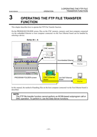
![3. OPERATING THE FTP FILE
TRANSFER FUNCTION OPERATION B-64014EN/04
3.1 DEVICE CHANGE ON THE PROGRAM FOLDER SCREEN
Procedure
1 Press the function key .
2 Press soft key [FOLDER] to display the PROGRAM FOLDER screen. (When there is no soft keys,
press the continue key.)
PROGRAM FOLDER screen
3 Press soft key [(OPRT)] then soft key [DEVICE CHANGE] to display the soft keys for selectable
devices.
4 When you press soft key [FTP HOST], the information displayed on the PROGRAM FOLDER
screen is changed to the contents (FTP TRANSFER HOST FILE LIST screen) of the hard disk of
the host computer to enable file operation.
- 124 -](https://image.slidesharecdn.com/b-64014en04-121129012902-phpapp02/85/B-64014-en-04-136-320.jpg)
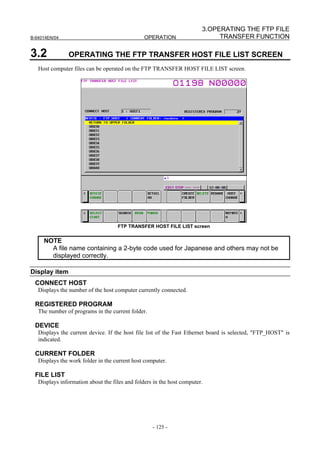
![3. OPERATING THE FTP FILE
TRANSFER FUNCTION OPERATION B-64014EN/04
Operation list
DEVICE CHANGE
Enables a device for display on the PROGRAM FOLDER screen. When selecting the host file list of the
Fast Ethernet board, press soft key [FTP HOST].
DETAIL OFF / DETAIL ON
Switches the file list information to overall display or detail display.
CREATE FOLDER
Creates a sub-folder under the current work folder.
DELETE
Deletes a file or folder.
RENAME
Renames a file or folder.
HOST CHANGE
Changes the connected host computer.
SEARCH
Searches for a file in the current folder.
READ (For the Series 30i/31i/32i-A)
F INPUT (For the Series 30i/31i/32i-B)
When the CNC is placed in the EDIT mode and CNC parameter No.20 is equal 5, it is possible to input
NC programs in the host computer to program memory of the CNC.
PUNCH (For the Series 30i/31i/32i-A)
F OUTPUT (For the Series 30i/31i/32i-B)
When the CNC is placed in the EDIT mode and CNC parameter No.20 is equal 5, it is possible to output
NC programs in program memory of the CNC to the host computer.
REFRESH
Updates the information displayed on the FTP TRANSFER HOST FILE LIST screen.
3.2.1 Displaying and Operating the File List
RENAME, DETAIL OFF, DETAIL ON
The contents of the file list can be updated and displayed.
1 Press soft key [REFRESH] to update the contents of the file list.
2 Press soft key [DETAIL OFF] to display a file name only.
3 Press soft key [DETAIL ON] to display a file attribute, size, date, and file name.
NOTE
1 The information displayed with soft key [DETAIL ON] depends on the setting of
the FTP server on the host computer.
- 126 -](https://image.slidesharecdn.com/b-64014en04-121129012902-phpapp02/85/B-64014-en-04-138-320.jpg)
![3.OPERATING THE FTP FILE
B-64014EN/04 OPERATION TRANSFER FUNCTION
NOTE
2 When a file operation is performed in the detail display mode, the rightmost
information displayed on the screen is handled as the file name. For this reason,
the file operation may not be performed correctly depending on the displayed
information or file name. In this case, set the overall display mode and perform
the file operation.
MOVE FOLDER
A work folder can be moved.
1 By using cursor keys , select a folder to be moved.
2 Press the MDI key .
CREATE FOLDER
A new folder can be created.
1 Move to a new folder to be created.
2 Enter a desired folder name.
3 Press soft key [CREATE FOLDER].
DELETE
Specifying a file or folder
A file or folder can be deleted.
1 By using cursor keys , select a file or folder to be deleted.
2 Press soft key [DELETE].
• Press soft key [EXEC] for execution.
• Press soft key [CANCEL] for cancellation.
Specifying multiple files
Multiple files or folder can be deleted.
1 Press soft key [SELECT START].
2 By using cursor keys , select a file to be deleted.
3 Press soft key [SELECT].
A selected file is displayed in reverse video.
Repeat steps 2 and 3 for files to be deleted.
4 Press soft key [DELETE].
• Press soft key [EXEC] for execution.
• Press soft key [CANCEL] for cancellation.
NOTE
Up to 10 files can be selected at a time.
- 127 -](https://image.slidesharecdn.com/b-64014en04-121129012902-phpapp02/85/B-64014-en-04-139-320.jpg)
![3. OPERATING THE FTP FILE
TRANSFER FUNCTION OPERATION B-64014EN/04
DELETE (new specification)
Specifying a file or folder
A file or folder can be deleted.
1 Place the cursor on the name of a file or folder to be deleted.
2 Press soft key [DELETE].
• Press soft key [EXEC] for execution.
• Press soft key [CANCEL] for cancellation.
Selecting a range
Multiple files or folders can be deleted.
1 Press soft key [SELECT].
2 Place the cursor on the name of a file to be deleted and press soft key [RANGE SELECT].
3 By using cursor keys , select a range of files to be deleted.
A selected file is displayed in reverse video.
4 When you have selected a desired range, press soft key [DELETE].
• Press soft key [EXEC] for execution.
• Press soft key [CANCEL] for cancellation.
Selecting individual files or folders
Multiple files or folders can be deleted.
1 Press soft key [SELECT].
2 Place the cursor on the name of a file to be deleted and press soft key [SELECT].
A selected file is displayed in reverse video.
3 Repeat step 2 for all files to be selected.
4 When you have selected desired files, press soft key [DELETE].
• Press soft key [EXEC] for execution.
• Press soft key [CANCEL] for cancellation.
NOTE
1 Delete operation of the new specification is performed when bit 3 (PCP) of
parameter No. 11374 is set to 1 for the Series 30i/31i/32i-A or bit 4 (PCB) of
parameter No. 11374 is set to 0 for the Series 30i/31i/32i-B.
2 Up to 10 files can be selected at a time.
RENAME
A file or folder can be renamed.
1 By using cursor keys , select a file or folder to be renamed.
2 Key a new file name or folder name.
3 Press soft key [RENAME].
SEARCH
In the current work folder, a file can be found.
1 Enter a desired file name.
2 Press soft key [SEARCH],
- 128 -](https://image.slidesharecdn.com/b-64014en04-121129012902-phpapp02/85/B-64014-en-04-140-320.jpg)
![3.OPERATING THE FTP FILE
B-64014EN/04 OPERATION TRANSFER FUNCTION
HOST CHANGE
The connected host computer can be changed.
1 Press soft key [HOST CHANGE].
The connected host number changes in the order 1 → 2 → 3 → 1.
3.3 NC PROGRAM INPUT
NC programs in the host computer can be input to program memory of the CNC.
CAUTION
If bit 2 of NC parameter No. 3201 is set to 1, when an NC program having the
same file name as an NC program to be input is already present in program
memory, the existing NC program is overwritten.
NOTE
NC programs cannot be input simultaneously with an NC program output.
Procedure
1 Place the CNC in the EDIT mode.
2 Display the PROGRAM screen, PROGRAM FOLDER screen or FTP TRANSFER HOST LIST
screen.
3 Press soft key [READ] ([F INPUT] for the Series 30i/31i/32i/35i-B).
4 In the key-in buffer, enter the name of a file to be input on the host computer, and press soft key [F
SET]. When the file name on the host computer is not set, file name "ALL-PROG.TXT" is used by
default.
5 To rename the input file and input it into program memory, enter the new file name in the key-in
buffer, and press soft key [P SET].
6 Press soft key [EXEC].
7 During inputting, "INPUT" blinks in the lower right part of the screen.
3.4 NC PROGRAM OUTPUT
NC programs in program memory of the CNC can be output to the host computer.
NOTE
NC programs cannot be output simultaneously with an NC program input.
Procedure
1 Place the CNC in the EDIT mode.
2 Display the PROGRAM screen, PROGRAM FOLDER screen or FTP TRANSFER HOST LIST
screen.
3 Press soft key [PUNCH] ([F OUTPUT] for the Series 30i/31i/32i/35i-B).
- 129 -](https://image.slidesharecdn.com/b-64014en04-121129012902-phpapp02/85/B-64014-en-04-141-320.jpg)
![3. OPERATING THE FTP FILE
TRANSFER FUNCTION OPERATION B-64014EN/04
4 In the key-in buffer, enter the name of a file to be output in program memory, and press soft key [P
SET].
When a specific file name in program memory is not set, all files in the foreground folder are
assumed to be output.
5 To rename the output file and output it to the host computer, enter the new file name in the key-in
buffer, and press soft key [F SET].
When only a file in program memory is specified, but no file name on the host computer is specified,
a file is created with the file name used in program memory.
6 Press soft key [EXEC].
7 During outputting, "OUTPUT" blinks in the lower right part of the screen.
NOTE
When neither file in program memory nor file name on the host computer is
specified, all files in the foreground folder are output with file name
"ALL-PROG.TXT" to the host computer.
- 130 -](https://image.slidesharecdn.com/b-64014en04-121129012902-phpapp02/85/B-64014-en-04-142-320.jpg)


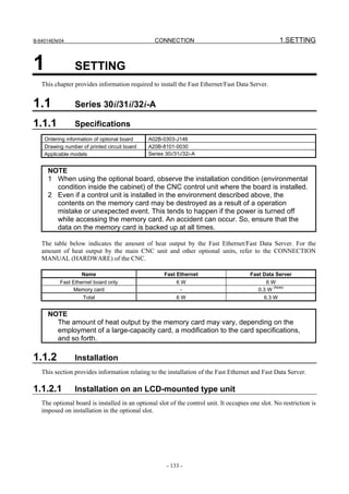
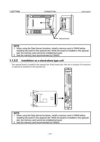
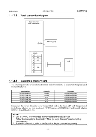
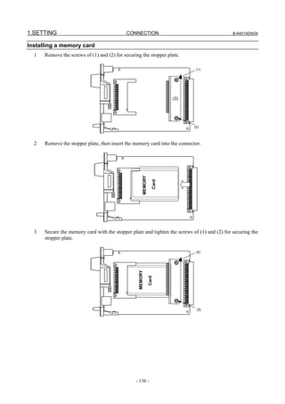
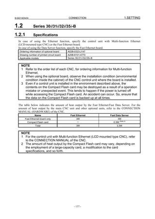
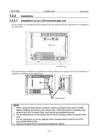
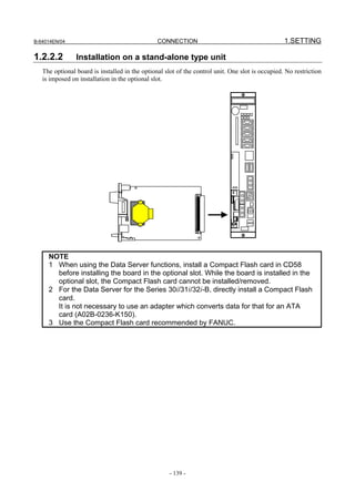
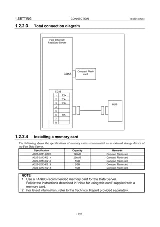
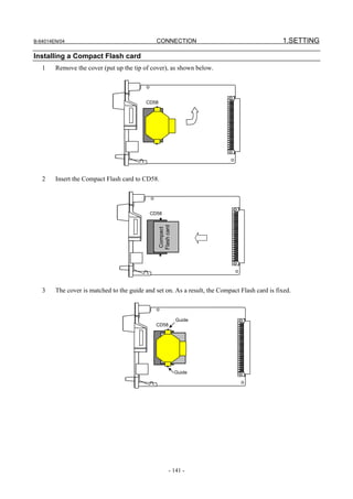
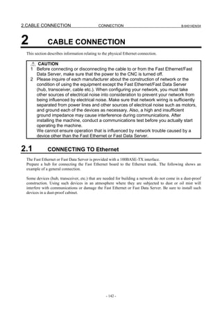
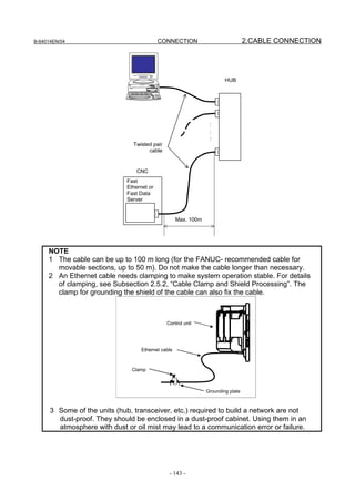
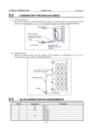
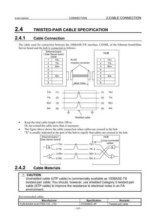
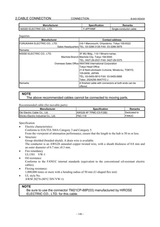
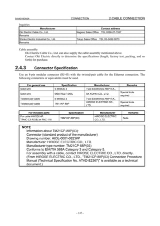
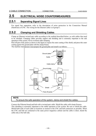
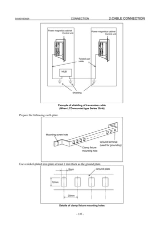
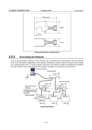
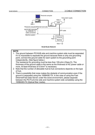
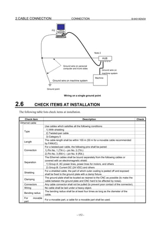
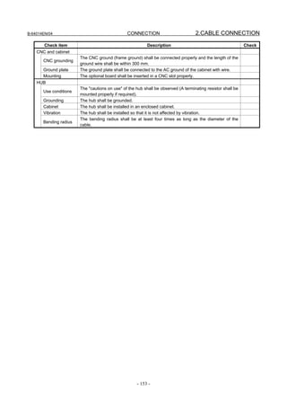


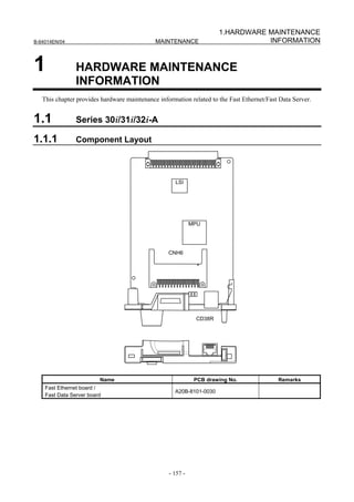
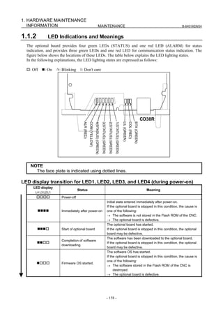
![1.HARDWARE MAINTENANCE
B-64014EN/04 MAINTENANCE INFORMATION
LED display
Status Meaning
L4 L3 L2 L1
Initialization of the software OS is completed.
If the optional board is stopped in this condition, the cause is
Completion of software OS one of the following:
initialization → The software stored in the Flash ROM of the CNC is
destroyed.
→ The optional board is defective.
The Ethernet parameters have been read.
If the optional board is stopped in this condition, the cause is
Completion of parameter
one of the following:
reading
→ The Ethernet option or Data Server option is not installed.
→ The IP address or subnet mask is not set.
Start completion The optional board has started normally.
LED display for LED1, LED2, LED3, and LED4 (during normal operation)
LED display
Status Meaning
L4 L3 L2 L1
Normal status The board is operating normally.
LED display for BTX, LIL, COM, and ALM (during normal operation)
LED display Status Meaning
100BASE-TX connection in
BTX The communication rate is 100BASE-TX.
progress
10BASE-T connection in
BTX The communication rate is 10BASE-T.
progress
LIL Connected to hub The board is connected to the hub.
Transmission/
COM Data is being transmitted or received.
reception in progress
ALM No alarm No alarm is issued
LED display for LED1, LED2, LED3, and LED4 (when abnormality occurs)
The STATUS LEDs are turned on and off repeatedly with long on-time and short on-time.
LED display LED display
[Long [Short
Status Description
on-time] on-time]
4321 4321
A defect on another board or a problem on another
Error on another board
optional board was detected.
Software has a problem, or the optional board is
Bus error
defective.
Parity alarm The optional board is defective.
Illegal general Software has a problem, or the optional board is
instruction defective.
Software has a problem, or the optional board is
Illegal slot instruction
defective.
Software has a problem, or the optional board is
CPU address error
defective.
NOTE
If an error occurs with the LEDs turned on and off with long on-time and short
on-time in a manner not indicated above, contact FANUC.
- 159 -](https://image.slidesharecdn.com/b-64014en04-121129012902-phpapp02/85/B-64014-en-04-171-320.jpg)

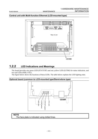
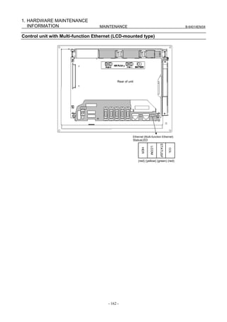
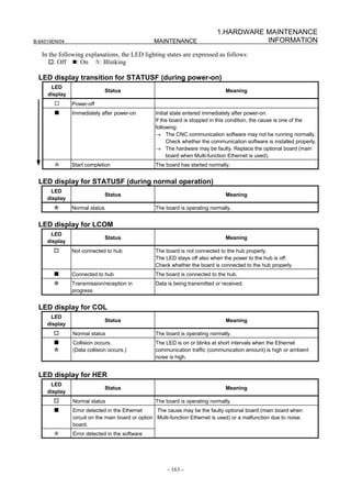
![2. SOFTWARE MAINTENANCE
INFORMATION MAINTENANCE B-64014EN/04
2 SOFTWARE MAINTENANCE
INFORMATION
This chapter provides software maintenance information related to the Fast Ethernet/Fast Data Server.
2.1 Ethernet LOG
A log related to the Fast Ethernet/Fast Data Server is displayed.
ETHERNET LOG screen
Procedure
1 Press the function key .
2 Press soft key [BOARD LOG] ([ETHER LOG] for the Series 30i/31i/32i/35i-B) to display the LOG
screen for the Fast Ethernet/Fast Data Server. (If the soft key is not found, press the continuous
menu key.)
LOG screen
The latest log information is displayed at the top of the screen. At the right end of a log item, the
occurrence date and time of the log item is indicated. Date and time data is indicated in the format
"MMM.DD hh:mm:ss", where MMM represents a month, DD represents a day, hh represents hours, mm
represents minutes, and ss represents seconds.
The top item in the example above indicates "09:36:14 on August 7".
To clear the log information, press soft key [(OPRT)] then soft key [CLEAR].
By operating the LOG screen of the Fast Ethernet/Fast Data Server, log information can be displayed for
each function.
- 164 -](https://image.slidesharecdn.com/b-64014en04-121129012902-phpapp02/85/B-64014-en-04-176-320.jpg)
![2.SOFTWARE MAINTENANCE
B-64014EN/04 MAINTENANCE INFORMATION
(1) Soft key [ALL]
This soft key displays all log information related to the Fast Ethernet/Fast Data Server.
(2) Soft key [COMMON]
This soft key displays log information related to the parameter setting and basic communication
function of the Fast Ethernet/Fast Data Server.
(3) Soft key [FOCAS2]
This soft key displays log information related to the FOCAS2/Ethernet function.
(4) Soft key [DATA SERVER]
This soft key displays log information related to the Data Server.
(5) Soft key [REMOTE DIAG]
This soft key displays log information related to the machine remote diagnosis functions.
NOTE
The Ethernet log information is stored in volatile memory and is lost when the
power to the CNC is turned off. Check the log information when an error occurs.
Error
Log message Meaning and action to be taken
number
E-0118 Error occurred while wait for FOCAS2 pdu A communication error occurred due to one of the
E-0119 following causes:
→ The network quality degraded, data could not be
received from the personal computer with which to
communicate, and the logical communication path
was disconnected.
→ The software component on the personal computer
with which to communicate forcibly disconnected the
logical communication path.
→ The Ethernet cable was disconnected.
E-011A All communication paths are busy All FOCAS2/Ethernet communication paths are being
used.
E-0126 No response from RMT DIAG server The IP address of the machine remote diagnosis
accepting server may be invalid or the power to the
machine remote diagnosis accepting server may be off.
Check whether the IP address of the machine remote
diagnosis accepting server is valid and whether the
power to the machine remote diagnosis accepting
server is on.
Alternatively, the machine remote diagnosis accepting
server may not respond to the PING command to
increase the security level (such as a firewall setting).
Set bit 1 of CNC parameter No. 905 to "1" and connect
the server again.
E-012D No response from router The IP address of the router may be invalid or the
power to the router may be off. Check whether the IP
address of the router is valid and whether the power to
the router is on.
- 165 -](https://image.slidesharecdn.com/b-64014en04-121129012902-phpapp02/85/B-64014-en-04-177-320.jpg)
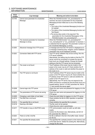
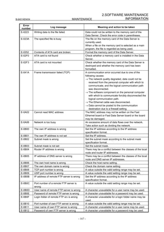
![2. SOFTWARE MAINTENANCE
INFORMATION MAINTENANCE B-64014EN/04
Error
Log message Meaning and action to be taken
number
E-0B13 Login folder of own FTP server is wrong A character unavailable for a login folder name may be
used.
E-0B14 IP address of Remote Diag is wrong Set the IP address of the machine remote diagnosis
accepting server according to the IP address
specification format.
E-0B15 Port number of Remote Diag is wrong A value outside the valid setting range may be set.
E-0B18 Cannot set because DHCP is available To set the item, disable the DHCP client function.
E-0B27 Unsolicited Message isn't available The software conditions to use the Unsolicited
Messaging function are not satisfied. Refer to Chapter
6, ”UNSOLICITED MESSAGING FUNCTION” in Part II,
“SPECIFICATION”.
E-0B29 Mode of Unsolicited Message is wrong The FOCAS2 function “cnc_wrunsolicprm2” can't be
execute in “CNC MODE”.
E-0B2A Status of Unsolicited Message is wrong The application of parameters for the Unsolicited
Messaging function failed because the status of the
Unsolicited Messaging function is not “Not Ready”.
This error occurred due to one of the following causes
when the status is not “Not Ready”:
→ The FOCAS2 function “cnc_wrunsolicprm2”, or
“cnc_unsolicstart” is executed.
→ The soft key [APPLY] is pressed.
E-0B2B Cannot refresh param of Unsolicited The application of parameters for the Unsolicited
Message Messaging function failed due to one of the following
causes:
→ The problem of E-0B29 or E-0B2A occurred.
→ The invalid value exists in the parameters for the
Unsolicited Messaging function.
E-0B44 Invalid value exists in Transmission The non-effective value exists in “TRANSMISSION
parameter of Unsolicited Message NUMBER” or “TRANSMISSION PARAMETER
(NO.1-3)”.
E-0B45 The total of Transmission size of The total transmission size of the parameters for the
Unsolicited Message exceeds the limitation Unsolicited Messaging function exceeds the available
maximum size. Refer to Subsection 6.1.2, “Setting by
CNC screen” in Part III, “SETTING” for the available
maximum size.
E-XXXX (No message) Internal error.
Report the error number.
The meaning of the error codes indicated in error messages E-02XX are as follows:
Error code Meaning
2 The available space of the memory card of the Data Server is insufficient.
10 The specified folder cannot be found.
11 The allowable number of entries is exceeded.
12 Access to a folder was rejected.
14 The specified file cannot be found.
15 Access to a file was rejected.
19 An attempt was made to access a file being used.
22 The specified file name is illegal.
28 A TV check error was detected.
36 The specified file is already present.
37 The folder is not empty.
39 The specified folder is already present.
48 The available file size is exceeded.
- 168 -](https://image.slidesharecdn.com/b-64014en04-121129012902-phpapp02/85/B-64014-en-04-180-320.jpg)
![2.SOFTWARE MAINTENANCE
B-64014EN/04 MAINTENANCE INFORMATION
2.2 ETHERNET CONNECTION CONFIRMATION
By transmitting the PING command, the CNC can check that a connection is made with the
communication destination.
PING screen (connection state confirmation)
Procedure
1 Press the function key .
2 Soft key [ETHER BOARD] ([ETHER NET] for the Series 30i/31i/32i/35i-B) is displayed. (If the
soft key is not found, press the continuous menu key.)
3 Press soft key [ETHER BOARD] then soft key [PING].
PING (CONNECT STATE) screen
4 Press soft key [(OPRT)] then soft key [PING FTP1] to send the PING command to host 1 to which
the Data Server function is connected. Similarly, press soft key [PING FTP2] and soft key [PING
FTP3] to send the PING command to connection hosts 2 and 3, respectively.
5 Press soft key [(OPRT)] then soft key [PING RMT1] to send the PING command to inquiry
destination 1 of the machine remote diagnosis functions. Similarly, press soft key [PING RMT2] to
send the command to inquiry destination 2 and soft key [PING RMT3] to inquiry destination 3.
- 169 -](https://image.slidesharecdn.com/b-64014en04-121129012902-phpapp02/85/B-64014-en-04-181-320.jpg)
![2. SOFTWARE MAINTENANCE
INFORMATION MAINTENANCE B-64014EN/04
The results of PING execution are as follows:
Execution results of PING
PING (SETTING) screen
Procedure
1 When sending the PING command to a desired destination, enter the destination address in
HOSTNAME (IP ADDRESS) on the PING (SETTING) screen. Moreover, set a desired execution
repeat value in REPEAT.
PING (SETTING) screen
2 After entering a host name (IP address) and repeat value, press soft key [(OPRT)] then soft key
[PING EXEC] to send the PING command to the specified destination.
3 To cancel the transmission of the PING command halfway, press soft key [PING CANCEL].
- 170 -](https://image.slidesharecdn.com/b-64014en04-121129012902-phpapp02/85/B-64014-en-04-182-320.jpg)
![2.SOFTWARE MAINTENANCE
B-64014EN/04 MAINTENANCE INFORMATION
2.3 COMMUNICATION STATE CONFIRMATION
The communication state of the Fast Ethernet/Fast Data Server detected by hardware can be checked.
COM STATE (SEND / RECEIVE) screen
Procedure
1 Press the function key .
2 Soft key [ETHER BOARD] ([ETHER NET] for the Series 30i/31i/32i/35i-B) is displayed. (If the
soft key is not found, press the continuous menu key.)
3 Press soft key [ETHER BOARD] then soft key [COM STATE] to display the COM STATE screen.
COM STATE screen
Display item
Display item Description
BAUDRATE Displays the communication rate and mode.
Communication rate: 100 Mbps or 10 Mbps
Communication mode: Full duplex or Half duplex
-------- : Not connected to HUB (only for the Series 30i/31i/32i/35i-B)
SEND PACKET Displays the number of sent packets.
SEND RETRYOVER Displays the number of errors detected during packet sending.
COLLISION
CARRIER SENSE LOST
NO CARRIER
FRAME LENGTH ERROR
RECEIVE PACKET Displays the number of received packets.
CRC ERROR Displays the number of errors detected during packet reception.
SHORT FRAME
LONG FRAME
ODD FRAME
OVERFLOW
PHY-LSI ERROR
- 171 -](https://image.slidesharecdn.com/b-64014en04-121129012902-phpapp02/85/B-64014-en-04-183-320.jpg)
![2. SOFTWARE MAINTENANCE
INFORMATION MAINTENANCE B-64014EN/04
2.4 COMMUNICATION SOFTWARE CONFIRMATION
The operating status of the software of the Fast Ethernet/Fast Data Server can be checked.
TASK STATE screen
Procedure
1 Press the function key .
2 Soft key [ETHER BOARD] ([ETHER NET] for the Series 30i/31i/32i/35i-B) is displayed. (If the
soft key is not found, press the continuous menu key.)
3 Press soft key [ETHER BOARD] then soft key [TASK STATE] to display the TASK STATE
screen.
TASK STATE screen
Display item
The meaning of each symbol is indicated below.
Symbol and meaning Function that can be checked
COMMON W : Data being processed (1) Operation status of the basic
D : Data being processed (2) function
E : Start of software
FOCAS2 #0 C : Waiting for connection from the host Operation status of the
W : Data being processed (1) FOCAS2/Ethernet functions
D : Data being processed (2)
N : FOCAS2 incapable of being executed
FOCAS2 #1 W : Data being processed (1)
D : Data being processed (2)
X : Not executed yet
FOCAS2 #2 W : Data being processed (1)
D : Data being processed (2)
X : Not executed yet
SCREEN W : Data being processed (1) Operation status of the CNC screen
D : Data being processed (2) display functions
X : Not executed yet
- 172 -](https://image.slidesharecdn.com/b-64014en04-121129012902-phpapp02/85/B-64014-en-04-184-320.jpg)
![2.SOFTWARE MAINTENANCE
B-64014EN/04 MAINTENANCE INFORMATION
Symbol and meaning Function that can be checked
UDP W : Data being processed (1) Operation status of the UDP broad
D : Data being processed (2) cast
X : Not executed yet
PMC W : Data being processed (1) Operation status of the FANUC
D : Data being processed (2) LADDER-III function
X : Not executed yet
DATASERVER W : Data being processed (1) Operation status of the Data Server
D : Data being processed (2) functions
X : Not executed yet
FTP SERVER W : Data being processed (1)
D : Data being processed (2)
Number : Number of sockets currently connected
REMOTE DIAG W : Data being processed (1) Operation status of the machine
D : Data being processed (2) remote diagnosis functions
X : Not executed yet
UNSOLICITED W : Data being processed (1) Operation status of the unsolicited
D : Data being processed (2) messaging function
N : Abnormal state
X : Not executed yet
Number : The existence signals is being transmitted
during this number is being counted.
FTP W : Data being processed (1) Operation status of the FTP file
D : Data being processed (2) transfer function
X : Not executed yet
2.5 FTP SERVER MAINTENANCE
The state of FTP clients connected to the FTP server can be checked and the FTP connection can be
disconnected forcedly.
NOTE
To use this function, the DataServer Explorer connection option (R953) is
required.
FTP Server MAINTENANCE screen (CLIENT LIST, CLIENT DETAIL)
Procedure
1 Press the function key .
2 Soft key [ETHER BOARD] ([ETHER NET] for the Series 30i/31i/32i/35i-B) is displayed. (If the
soft key is not found, press the continuous menu key.)
3 Press soft key [ETHER BOARD] then soft key [FTP SERVER] to display the FTP Server
MAINTENANCE screen (CLIENT LIST).
- 173 -](https://image.slidesharecdn.com/b-64014en04-121129012902-phpapp02/85/B-64014-en-04-185-320.jpg)
![2. SOFTWARE MAINTENANCE
INFORMATION MAINTENANCE B-64014EN/04
FTP Server MAINTENANCE screen (CLIENT LIST)
4 By using cursor keys , select a client, and press soft key [(OPRT)] then soft key
[DETAIL] to display the FTP Server MAINTENANCE screen (CLIENT DETAIL) displaying the
client information on the cursor.
The CLIENT DETAIL screen is as follows:
FTP Server MAINTENANCE screen (CLIENT DETAIL)
5 Press soft key [LIST] to display the CLIENT LIST screen again.
- 174 -](https://image.slidesharecdn.com/b-64014en04-121129012902-phpapp02/85/B-64014-en-04-186-320.jpg)
![2.SOFTWARE MAINTENANCE
B-64014EN/04 MAINTENANCE INFORMATION
Display item
Item Description
CLIENT Displays the IP address of the FTP client connected to the FTP server. (Example of
display format: "192.168.0.200")
- In the CLIENT DETAIL screen:
When the FTP connection is disconnected, "Disconnected" is displayed.
CONNECT TIME Display the connect time of the FTP client connected to the FTP server. The format
of the time is "hh:mm:ss" (hh: hour, mm: minute, ss: second).
The time display is updated automatically.
- In the CLIENT DETAIL screen:
When the FTP connection is disconnected, "--:--:--" is displayed.
NOTE
1 The CLIENT DETAIL screen cannot be displayed when any client does not exist
on the CLIENT LIST screen.
2 There is not the CLIENT DETAIL screen for 15-inch display unit.
Operation (DISCONNECT)
The selected client is disconnected on the CLIENT LIST screen and the CLIENT DETAIL screen.
1 When the CLIENT LIST screen is displayed, by using cursor keys , select a client to be
disconnected.
2 Press soft key [(OPRT)] then soft key [DISCONNECT].
3 Press soft key [EXEC] to disconnect the selected client.
When the CLIENT DETAIL screen is displayed, the displaying client is disconnected.
NOTE
An error occurs if the disconnect operation is attempted to execute when any
client does not exist on the CLIENT LIST screen, or when the connection with
the client is already disconnected on the CLIENT DETAIL screen.
Operation (ALL DISCONNECT)
All clients are disconnected on the CLIENT LIST screen.
1 Press soft key [(OPRT)] then soft key [ALL DISCON].
2 Press soft key [EXEC] to disconnect all clients.
NOTE
1 This operation can be executed only on the CLIENT LIST screen.
2 An error occurs if this operation is attempted to execute when any client does
not exist on the CLIENT LIST screen.
- 175 -](https://image.slidesharecdn.com/b-64014en04-121129012902-phpapp02/85/B-64014-en-04-187-320.jpg)
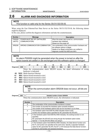
![2.SOFTWARE MAINTENANCE
B-64014EN/04 MAINTENANCE INFORMATION
Number Description
5 In the hardware option that DGN No.4400 indicates, a necessary software option is
not effective. The same hardware option is specified for NC parameter No.970,
No.971 or No.972.
6 In the hardware option that DGN No.4400 indicates, a necessary software option is
not effective.
2.7 COMMUNICATION RETRY MONITORING FUNCTION
When the Fast Ethernet function on the Series 30i/31i/32i/35i-B is used, Fast Ethernet communication
errors are checked at intervals of 10 seconds. If the number of errors detected during the last 1 minute
reaches the value set for parameter No. 11533, warning signal WETF is output.
Since the number of detected errors is checked at intervals of 10 seconds, the warning signal is also
output at intervals of 10 seconds. The signal output is reset by turning the power off, then on again.
NOTE
1 This function is valid only for the Series 30i/31i/32i/35i-B.
2 The maximum value for network error counters is 65535.
If an overflow occurs, no warning is issued and the error count returns to 0.
Parameter
11533 Warning value for the number of fast Ethernet error detection occurrences
[Input type] Parameter input
[Data type] Byte
[Unit of data] Number of detection occurrences/minute
[Valid data range] 0 to 128
Recommended setting = 0
Set a warning value for the number of Fast Ethernet error detection occurrences.
When the number of 1- minute error detection occurrences becomes higher than or equal
to the setting, the warning signal is output.
If the setting is 0, monitoring is performed on a 10 occurrences/minute basis.
NOTE
When this parameter is set, the power must be turned off before
operation is continued.
Fast Ethernet communication abnormality warning signal WETF<F0535.5>
[Classification] Output signal
[Operation] This signal is output when a warning occurs.
[Function] If the total number of various errors detected by the communication hardware of the Fast
Ethernet function is equal to or greater than the setting of parameter No. 11533 (standard
setting 0, which means 10 retries per one minute), this signal is set to 1.
Once this signal is set to 1, the value is kept until the CNC power is turned off.
- 177 -](https://image.slidesharecdn.com/b-64014en04-121129012902-phpapp02/85/B-64014-en-04-189-320.jpg)


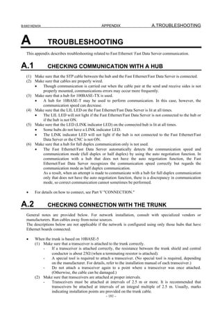
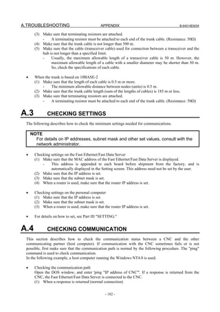
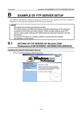
![B.EXAMPLE OF FTP SERVER SETUP APPENDIX B-64014EN/04
2. Click [Install Add-On Components].
3. Select [Internet Information Services (IIS)], then click the [Details] button to display the [Internet
Information Services (IIS)] dialog box. Next, check [File Transfer Protocol (FTP) Server].
- 186 -](https://image.slidesharecdn.com/b-64014en04-121129012902-phpapp02/85/B-64014-en-04-198-320.jpg)
![B-64014EN/04 APPENDIX B.EXAMPLE OF FTP SERVER SETUP
4. Click the [OK] button, then return to the previous screen. Next, click [Next]. The necessary files are
installed.
The installation is completed when the following screen appears:
Setting the Internet Information Service
1. Select [Start] → [Settings] → [Control Panel].
- 187 -](https://image.slidesharecdn.com/b-64014en04-121129012902-phpapp02/85/B-64014-en-04-199-320.jpg)
![B.EXAMPLE OF FTP SERVER SETUP APPENDIX B-64014EN/04
2. Double-click [Administrative Tools].
3. Double-click [Internet Service Manager] for activation.
- 188 -](https://image.slidesharecdn.com/b-64014en04-121129012902-phpapp02/85/B-64014-en-04-200-320.jpg)
![B-64014EN/04 APPENDIX B.EXAMPLE OF FTP SERVER SETUP
4. Double-click the computer name. Next, select [Default FTP Site] and right-click to display the menu.
Then, select Properties.
5. Select the [Home Directory] tab to display the [Home Directory] property sheet. Check [Read] and
[Write] in [FTP Site Directory]. In [Directory Listing Style], [MS-DOS] is selected by default.
However, it is recommended to check [UNIX]. If files are listed in UNIX format, whether each file
is accessible can be determined.
6. Upon completion of setting, click the [Apply] button.
In [Default FTP Site], the directory named "Inetpubftproot", set in [Local Path] above (in the drive
where Windows 2000 is installed), is assumed to be the home directory. So, directories under this
directory can be accessed.
So, with the default setting, NC programs need to be managed under this directory.
The home directory can be changed by setting the new directory in the [Local Path] of [FTP Site
Directory].
- 189 -](https://image.slidesharecdn.com/b-64014en04-121129012902-phpapp02/85/B-64014-en-04-201-320.jpg)
![B.EXAMPLE OF FTP SERVER SETUP APPENDIX B-64014EN/04
7. To access a directory other than the directories under the home directory, a virtual directory needs to
be set.
For details of a virtual directory, use the online help information of Windows 2000.
Login user setting
1. Select [Start] → [Settings] → [Control Panel].
2. Double-click the icon [Users and Passwords].
- 190 -](https://image.slidesharecdn.com/b-64014en04-121129012902-phpapp02/85/B-64014-en-04-202-320.jpg)
![B-64014EN/04 APPENDIX B.EXAMPLE OF FTP SERVER SETUP
3. Click the [Add] button, then enter necessary items such as a user name.
4. Click the [Next] button, then enter a password for the specified user name. (Unless a password is set,
access to the FTP server cannot be made correctly. So, be sure to enter a password.)
- 191 -](https://image.slidesharecdn.com/b-64014en04-121129012902-phpapp02/85/B-64014-en-04-203-320.jpg)
![B.EXAMPLE OF FTP SERVER SETUP APPENDIX B-64014EN/04
5. Click the [Next] button, then set an access right to be granted.
The access right set here can affect the capability to read from and write to a file in FTP-based
communication. Use care when setting an access right.
6. Click the [Finish] button. The entered user name is registered, and the user can log in by using the
user name and password.
Stopping password expiration for a login user
If the password expiration is not stopped, when the password expires, login is disabled, preventing FTP
communication.
Therefore, stop the password expiration as necessary.
When a password has expired, it is necessary to set the password again.
1. Select [Start] → [Settings] → [Control Panel].
- 192 -](https://image.slidesharecdn.com/b-64014en04-121129012902-phpapp02/85/B-64014-en-04-204-320.jpg)
![B-64014EN/04 APPENDIX B.EXAMPLE OF FTP SERVER SETUP
2. Double-click the icon [Users and Passwords].
3. Click the [Advanced] tab.
- 193 -](https://image.slidesharecdn.com/b-64014en04-121129012902-phpapp02/85/B-64014-en-04-205-320.jpg)
![B.EXAMPLE OF FTP SERVER SETUP APPENDIX B-64014EN/04
4. Click the [Advanced] button.
5. Double-click [Users]. A list of registered users is displayed.
- 194 -](https://image.slidesharecdn.com/b-64014en04-121129012902-phpapp02/85/B-64014-en-04-206-320.jpg)
![B-64014EN/04 APPENDIX B.EXAMPLE OF FTP SERVER SETUP
6. Double-click the user name for which you want to change the password setting.
For example, double-click "dtsvr".
7. Check [Password never expires] and then click the [OK] button. The password expiration is stopped.
- 195 -](https://image.slidesharecdn.com/b-64014en04-121129012902-phpapp02/85/B-64014-en-04-207-320.jpg)
![B.EXAMPLE OF FTP SERVER SETUP APPENDIX B-64014EN/04
B.2 SETTING UP FTP SERVER OF Windows XP Professional
(FOR INTERNET INFORMATION SERVICE)
NOTE
Windows XP Home Edition does not have IIS (Internet Information Service).
Installing the Internet Information Service
1. Open [Control Panel] of Windows XP Professional.
2. Double-click [Add or Remove Programs].
- 196 -](https://image.slidesharecdn.com/b-64014en04-121129012902-phpapp02/85/B-64014-en-04-208-320.jpg)
![B-64014EN/04 APPENDIX B.EXAMPLE OF FTP SERVER SETUP
3. Double-click [Add/Remove Windows Components].
4. Select [Internet Information Services (IIS)], then click the [Details] button to display the [Internet
Information Services (IIS)] dialog box. Next, check [File Transfer Protocol (FTP) Service].
- 197 -](https://image.slidesharecdn.com/b-64014en04-121129012902-phpapp02/85/B-64014-en-04-209-320.jpg)
![B.EXAMPLE OF FTP SERVER SETUP APPENDIX B-64014EN/04
5. Click the [OK] button, then return to the previous screen. Next, click [Next].
6. The dialog box above is displayed, and the necessary files are installed.
7. The installation is completed when the screen above is displayed.
Setting the Internet Information Service
1. Open [Control Panel] of Windows XP Professional.
- 198 -](https://image.slidesharecdn.com/b-64014en04-121129012902-phpapp02/85/B-64014-en-04-210-320.jpg)
![B-64014EN/04 APPENDIX B.EXAMPLE OF FTP SERVER SETUP
2. Click [Performance and Maintenance].
3. Click [Administrative Tools].
- 199 -](https://image.slidesharecdn.com/b-64014en04-121129012902-phpapp02/85/B-64014-en-04-211-320.jpg)
![B.EXAMPLE OF FTP SERVER SETUP APPENDIX B-64014EN/04
4. Double-click [Internet Information Services].
5. Double-click [FTP Site], right-click [Default FTP Site] to display a menu, then select Properties.
- 200 -](https://image.slidesharecdn.com/b-64014en04-121129012902-phpapp02/85/B-64014-en-04-212-320.jpg)
![B-64014EN/04 APPENDIX B.EXAMPLE OF FTP SERVER SETUP
6. Select the [Home Directory] tab to display the [Home Directory] property sheet.
Check [Read] and [Write] in [FTP Site Directory]. In [Directory Listing Style], [MS-DOS] is
selected by default. However, it is recommended to check [UNIX]. If files are listed in UNIX format,
whether each file is accessible can be determined.
7. Then, click the [OK] button.
In the standard [Default FTP Site], the directory Inetputftproot (on the drive where Windows XP is
installed) is the home directory, and only the directories under the home directory can be accessed.
To use a directory other than the default directory as a home directory, modify the local path of [FTP
Site Directory] mentioned in step 6 above.
8. To access a directory other than the directories under the home directory set in step 7 above, a
virtual directory needs to be set.
For details of a virtual directory, use information such as the online help information of Windows
XP.
- 201 -](https://image.slidesharecdn.com/b-64014en04-121129012902-phpapp02/85/B-64014-en-04-213-320.jpg)
![B.EXAMPLE OF FTP SERVER SETUP APPENDIX B-64014EN/04
Login user setting
1. Open [Control Panel] of Windows XP Professional.
2. Double-click the icon of [User Accounts].
- 202 -](https://image.slidesharecdn.com/b-64014en04-121129012902-phpapp02/85/B-64014-en-04-214-320.jpg)
![B-64014EN/04 APPENDIX B.EXAMPLE OF FTP SERVER SETUP
3. Click [Create a new account], then enter a desired user name.
4. Click the [Next] button, then set an account type.
The access right set here can affect the capability to read from and write to a file in FTP-based
communication. Use care when setting an access right.
- 203 -](https://image.slidesharecdn.com/b-64014en04-121129012902-phpapp02/85/B-64014-en-04-215-320.jpg)
![B.EXAMPLE OF FTP SERVER SETUP APPENDIX B-64014EN/04
5. Click the [Create Account] button, then the creation of an account is completed.
6. For password setting, click the previously created account in [or pick an account to change]. (The
FTP server cannot be accessed without setting a password. So, be sure to execute this step.)
7. Click [Create a password], then enter a password for the specified user name.
- 204 -](https://image.slidesharecdn.com/b-64014en04-121129012902-phpapp02/85/B-64014-en-04-216-320.jpg)
![B-64014EN/04 APPENDIX B.EXAMPLE OF FTP SERVER SETUP
8. Click the [Create Password] button to register the entered password. By using the account registered
this time, the user can log in to the FTP server.
Stopping password expiration for a login user
If the password expiration is not stopped, the Data Server will not be able to communicate with the FTP
server at the time of expiring the password.
If you are necessary, stop the password expiration.
If the password is expired, it is necessary that you re-enter the password.
1. Select [Start] → [All Programs] → [Accessories] → [Command Prompt].
2. Input “net user login-user /expires:never”.
3. If the above message is displayed, the password expiration is stopped.
Confirming the Firewall function of Windows XP
Because the Internet Connection Firewall function is included in the Windows XP Professional, the Data
Server cannot communicate with the FTP server.
If the FTP connection cannot be established, confirm the following setting of the Internet Connection
Firewall function.
NOTE
When settings are made as described below, the FTP server functions and
response to PING, which have been disabled by the network security function,
are enabled.
Therefore, when making the following settings, consult with your network
administrator, and take special care.
In some cases, it becomes necessary to isolate the network from the outside as
required.
- 205 -](https://image.slidesharecdn.com/b-64014en04-121129012902-phpapp02/85/B-64014-en-04-217-320.jpg)
![B.EXAMPLE OF FTP SERVER SETUP APPENDIX B-64014EN/04
1. Open [Control Panel] of Windows XP Professional.
2. Click the icon of [Network and Internet Connections].
3. Click the icon [Network Connections].
- 206 -](https://image.slidesharecdn.com/b-64014en04-121129012902-phpapp02/85/B-64014-en-04-218-320.jpg)
![B-64014EN/04 APPENDIX B.EXAMPLE OF FTP SERVER SETUP
4. Right-click the icon [Local Area Connection] to display the menu. Then, select Properties.
5. Select the [Advanced] tab.
6. If [Internet Connection Firewall] is not checked, the Internet Connection Firewall function does not
work. Then, the following confirmations are not necessary.
- 207 -](https://image.slidesharecdn.com/b-64014en04-121129012902-phpapp02/85/B-64014-en-04-219-320.jpg)
![B.EXAMPLE OF FTP SERVER SETUP APPENDIX B-64014EN/04
7. If [Internet Connection Firewall] is checked, click the [Settings…] button.
8. If the [FTP Server] check-box is not checked, the FTP server function does not work. Check the
[FTP Server] check-box.
When the [FTP Server] check-box is checked, the following window is displayed. Then, click the
[OK] button.
- 208 -](https://image.slidesharecdn.com/b-64014en04-121129012902-phpapp02/85/B-64014-en-04-220-320.jpg)
![B-64014EN/04 APPENDIX B.EXAMPLE OF FTP SERVER SETUP
9. Select the [ICMP] tab.
- 209 -](https://image.slidesharecdn.com/b-64014en04-121129012902-phpapp02/85/B-64014-en-04-221-320.jpg)
![B.EXAMPLE OF FTP SERVER SETUP APPENDIX B-64014EN/04
10. If the [Allow incoming echo request] check-box is not checked, the Data Server function cannot find
the FTP server at the start of communication.
At the start of communication of Data Server, if the message “[FTP] (IP-address) IS NOT
AVAILABLE” is displayed, check this check-box.
Confirming the firewall function when Windows XP (Service Pack 2) is used
When Windows XP Professional (Service Pack 2) is used, a different firewall setting procedure is used.
1. Open [Control Panel] of Windows XP Professional.
- 210 -](https://image.slidesharecdn.com/b-64014en04-121129012902-phpapp02/85/B-64014-en-04-222-320.jpg)
![B-64014EN/04 APPENDIX B.EXAMPLE OF FTP SERVER SETUP
2. Double-click [Security Center] to start it.
3. Click [Windows Firewall] displayed at the bottom.
- 211 -](https://image.slidesharecdn.com/b-64014en04-121129012902-phpapp02/85/B-64014-en-04-223-320.jpg)
![B.EXAMPLE OF FTP SERVER SETUP APPENDIX B-64014EN/04
4. Select the [Advanced] tab.
5. Click the [Settings] button of [ICMP].
- 212 -](https://image.slidesharecdn.com/b-64014en04-121129012902-phpapp02/85/B-64014-en-04-224-320.jpg)
![B-64014EN/04 APPENDIX B.EXAMPLE OF FTP SERVER SETUP
6. If [Allow incoming echo request] is not checked, check it, and click the [OK] button.
This allows a response to be made to PING from other devices.
7. Select the [Exceptions] tab.
8. Click the [Add Port] button, and make settings as follows:
- 213 -](https://image.slidesharecdn.com/b-64014en04-121129012902-phpapp02/85/B-64014-en-04-225-320.jpg)
![B.EXAMPLE OF FTP SERVER SETUP APPENDIX B-64014EN/04
9. Click the [OK] button.
- 214 -](https://image.slidesharecdn.com/b-64014en04-121129012902-phpapp02/85/B-64014-en-04-226-320.jpg)
![B-64014EN/04 APPENDIX B.EXAMPLE OF FTP SERVER SETUP
B.3 SETTING UP FTP SERVER OF Windows Vista (FOR
INTERNET INFORMATION SERVICE)
NOTE
Windows Vista Home Basic and Windows Vista Home Premium do not have IIS
(Internet Information Service).
Installing the Internet Information Service
1. Open [Control Panel] of Windows Vista.
2. Click [Programs].
- 215 -](https://image.slidesharecdn.com/b-64014en04-121129012902-phpapp02/85/B-64014-en-04-227-320.jpg)
![B.EXAMPLE OF FTP SERVER SETUP APPENDIX B-64014EN/04
3. Click [Turn Windows features on or off].
4. Expand [Internet Information Services], then check [FTP Management Console] and [FTP Server] in
[FTP Publishing Service]. Next, click the [OK] button.
- 216 -](https://image.slidesharecdn.com/b-64014en04-121129012902-phpapp02/85/B-64014-en-04-228-320.jpg)
![B-64014EN/04 APPENDIX B.EXAMPLE OF FTP SERVER SETUP
5. The dialog box below is displayed, and the necessary files are installed.
6. The installation is completed when the dialog box above and [Windows Features] dialog box are
finished.
Setting the Internet Information Service
1. Open [Control Panel] of Windows Vista.
- 217 -](https://image.slidesharecdn.com/b-64014en04-121129012902-phpapp02/85/B-64014-en-04-229-320.jpg)
![B.EXAMPLE OF FTP SERVER SETUP APPENDIX B-64014EN/04
2. Click [System and Maintenance].
3. Click [Administrative Tools].
- 218 -](https://image.slidesharecdn.com/b-64014en04-121129012902-phpapp02/85/B-64014-en-04-230-320.jpg)
![B-64014EN/04 APPENDIX B.EXAMPLE OF FTP SERVER SETUP
4. Double-click [Services] to start it.
5. Select [FTP Publishing Service], right-click it to display a menu, then select Properties.
- 219 -](https://image.slidesharecdn.com/b-64014en04-121129012902-phpapp02/85/B-64014-en-04-231-320.jpg)
![B.EXAMPLE OF FTP SERVER SETUP APPENDIX B-64014EN/04
6. Display the [General] property sheet.
Change [Manual] to [Automatic] in [Startup type] and click the [Start] button in [Service status],
then click the [OK] button.
End [Services].
7. Return to [Administrative Tools], then Double-click [Internet Information Services (IIS) 6.0
Manager] ([IIS6 Manager]) to start it.
- 220 -](https://image.slidesharecdn.com/b-64014en04-121129012902-phpapp02/85/B-64014-en-04-232-320.jpg)
![B-64014EN/04 APPENDIX B.EXAMPLE OF FTP SERVER SETUP
8. Double-click [FTP Sites], right-click [Default FTP Site] to display a menu, then select Properties.
9. Select the [Home Directory] tab to display the [Home Directory] property sheet.
Check [Read] and [Write] in [FTP site directory]. In [Directory listing style], [MS-DOS] is selected
by default. However, it is recommended to check [UNIX]. If files are listed in UNIX format,
whether each file is accessible can be determined.
- 221 -](https://image.slidesharecdn.com/b-64014en04-121129012902-phpapp02/85/B-64014-en-04-233-320.jpg)
![B.EXAMPLE OF FTP SERVER SETUP APPENDIX B-64014EN/04
10. Then, click the [OK] button.
In the standard [Default FTP Site], the directory inetpubftproot (on the drive where Windows Vista
is installed) is the home directory, and only the directories under the home directory can be accessed.
To use a directory other than the default directory as a home directory, modify the local path of [FTP
site directory] mentioned in step 9 above.
11. To access a directory other than the directories under the home directory set in step 10 above, a
virtual directory needs to be set.
For details of a virtual directory, use information such as the online help information of Windows
Vista.
Login User Setting
1. Open [Control Panel] of Windows Vista.
2. Click [User Accounts].
- 222 -](https://image.slidesharecdn.com/b-64014en04-121129012902-phpapp02/85/B-64014-en-04-234-320.jpg)
![B-64014EN/04 APPENDIX B.EXAMPLE OF FTP SERVER SETUP
3. Click [Add or remove user accounts].
4. Click [Create a new account], then enter a desired user name and set an account type.
The access right set here can affect the right to read from and write to a file in FTP-based
communication. Use care when setting an access right.
- 223 -](https://image.slidesharecdn.com/b-64014en04-121129012902-phpapp02/85/B-64014-en-04-235-320.jpg)
![B.EXAMPLE OF FTP SERVER SETUP APPENDIX B-64014EN/04
5. Click the [Create Account] button, then the creation of an account is completed.
6. For password setting, click the previously created account. (The FTP server cannot be accessed
without setting a password. So, be sure to execute this step.)
- 224 -](https://image.slidesharecdn.com/b-64014en04-121129012902-phpapp02/85/B-64014-en-04-236-320.jpg)
![B-64014EN/04 APPENDIX B.EXAMPLE OF FTP SERVER SETUP
7. Click [Create a password], then enter a password for the specified user name.
8. Click the [Create password] button to register the entered password. By using the account registered
this time, the user can log in to the FTP server.
Stopping password expiration for a login user
If the password expiration is not stopped, the Data Server will not be able to communicate with the FTP
server at the time of expiring the password.
If you are necessary, stop the password expiration.
If the password is expired, it is necessary that you re-enter the password.
1. Select [Start] → [All Programs] → [Accessories] → [Command Prompt], right-click it to display a
menu, then select [Run as administrator].
- 225 -](https://image.slidesharecdn.com/b-64014en04-121129012902-phpapp02/85/B-64014-en-04-237-320.jpg)
![B.EXAMPLE OF FTP SERVER SETUP APPENDIX B-64014EN/04
2. Input “net user login-user /expires:never”.
3. If the above message is displayed, the password expiration is stopped.
Confirming the Firewall function of Windows Vista
Because the Internet Connection Firewall function is included in the Windows Vista, the Data Server may
not communicate with the FTP server.
If the FTP connection cannot be established, confirm the following setting of the Internet Connection
Firewall function.
NOTE
When settings are made as described below, the FTP server functions and
response to PING, which have been disabled by the network security function,
are enabled.
Therefore, when making the following settings, consult with your network
administrator, and take special care.
In some cases, it becomes necessary to isolate the network from the outside as
required.
1. Open [Control Panel] of Windows Vista.
- 226 -](https://image.slidesharecdn.com/b-64014en04-121129012902-phpapp02/85/B-64014-en-04-238-320.jpg)
![B-64014EN/04 APPENDIX B.EXAMPLE OF FTP SERVER SETUP
2. Click [System and Maintenance].
3. Click [Administrative Tools].
- 227 -](https://image.slidesharecdn.com/b-64014en04-121129012902-phpapp02/85/B-64014-en-04-239-320.jpg)
![B.EXAMPLE OF FTP SERVER SETUP APPENDIX B-64014EN/04
4. Double-click [Windows Firewall with Advanced Security] to start it.
5. Click [Inbound Rules], select [File and Printer Sharing (Echo Request - ICMPv4 - In)] from the list,
right-click it to display a menu, then select Properties.
- 228 -](https://image.slidesharecdn.com/b-64014en04-121129012902-phpapp02/85/B-64014-en-04-240-320.jpg)
![B-64014EN/04 APPENDIX B.EXAMPLE OF FTP SERVER SETUP
6. Display the [General] property sheet.
Check [Enabled] in [General], then click the [OK] button.
End [Windows Firewall with Advanced Security].
7. Return to [Control Panel], then click [Security].
- 229 -](https://image.slidesharecdn.com/b-64014en04-121129012902-phpapp02/85/B-64014-en-04-241-320.jpg)
![B.EXAMPLE OF FTP SERVER SETUP APPENDIX B-64014EN/04
8. Click [Windows Firewall].
9. Click [Change settings].
- 230 -](https://image.slidesharecdn.com/b-64014en04-121129012902-phpapp02/85/B-64014-en-04-242-320.jpg)
![B-64014EN/04 APPENDIX B.EXAMPLE OF FTP SERVER SETUP
10. Select the [Exceptions] tab.
Check [FTP Server], then click the [OK] button.
- 231 -](https://image.slidesharecdn.com/b-64014en04-121129012902-phpapp02/85/B-64014-en-04-243-320.jpg)
![B.EXAMPLE OF FTP SERVER SETUP APPENDIX B-64014EN/04
B.4 SETTING UP FTP SERVER OF Windows 7 (FOR
INTERNET INFORMATION SERVICE)
NOTE
The FTP Server features depend on the Edition of Windows 7.
Windows 7 Professional, Enterprise, and Ultimate have the FTP Server features.
The setting described above is just an example.
Installing the Internet Information Service
1. Open [Control Panel] of Windows 7.
2. Click [Programs].
- 232 -](https://image.slidesharecdn.com/b-64014en04-121129012902-phpapp02/85/B-64014-en-04-244-320.jpg)
![B-64014EN/04 APPENDIX B.EXAMPLE OF FTP SERVER SETUP
3. Click [Turn Windows features on or off].
4. Expand [Internet Information Services], then check [FTP Service] in [FTP Server] and [IIS
Management Console] in [Web Management Tools]. Next, click the [OK] button.
- 233 -](https://image.slidesharecdn.com/b-64014en04-121129012902-phpapp02/85/B-64014-en-04-245-320.jpg)
![B.EXAMPLE OF FTP SERVER SETUP APPENDIX B-64014EN/04
5. The dialog box below is displayed, and the necessary files are installed.
6. The installation is completed when the dialog box above and [Windows Features] dialog box are
finished.
Setting the Internet Information Service
1. Open [Control Panel] of Windows 7.
- 234 -](https://image.slidesharecdn.com/b-64014en04-121129012902-phpapp02/85/B-64014-en-04-246-320.jpg)
![B-64014EN/04 APPENDIX B.EXAMPLE OF FTP SERVER SETUP
2. Click [System and Security].
3. Click [Administrative Tools].
- 235 -](https://image.slidesharecdn.com/b-64014en04-121129012902-phpapp02/85/B-64014-en-04-247-320.jpg)
![B.EXAMPLE OF FTP SERVER SETUP APPENDIX B-64014EN/04
4. Double-click [Services] to start it.
5. Select [Microsoft FTP Service], right-click it to display a menu, then select Properties.
- 236 -](https://image.slidesharecdn.com/b-64014en04-121129012902-phpapp02/85/B-64014-en-04-248-320.jpg)
![B-64014EN/04 APPENDIX B.EXAMPLE OF FTP SERVER SETUP
6. Display the [General] property sheet.
Choose [Automatic] from [Startup type] drop-down list. Next, if [Service status] is not [Started],
click the [Start] button to start FTP service, then click the [OK] button to end [Services].
- 237 -](https://image.slidesharecdn.com/b-64014en04-121129012902-phpapp02/85/B-64014-en-04-249-320.jpg)
![B.EXAMPLE OF FTP SERVER SETUP APPENDIX B-64014EN/04
7. Return to [Administrative Tools], then double-click [Internet Information Services (IIS) Manager] to
start it.
- 238 -](https://image.slidesharecdn.com/b-64014en04-121129012902-phpapp02/85/B-64014-en-04-250-320.jpg)
![B-64014EN/04 APPENDIX B.EXAMPLE OF FTP SERVER SETUP
8. Right-click Computer name(“PC1” in the following figure) to display a left side menu, then select
[Add FTP Site...].
9. The [Site Information] dialog box below is displayed. Input any site name in [FTP site name:] and
physical path of the home directory in [Physical path:].
The physical path is the home directory, and only the directories under the home directory can be
accessed.
Click [Next] button.
10. The [Binding and SSL setting] dialog box below is displayed.
Input the IP address and port number (usually 21) in [IP Address] and [Port].
Check [Start FTP site automatically] and select [No SSL] in [SSL].
Click [Next] button.
- 239 -](https://image.slidesharecdn.com/b-64014en04-121129012902-phpapp02/85/B-64014-en-04-251-320.jpg)
![B.EXAMPLE OF FTP SERVER SETUP APPENDIX B-64014EN/04
11. The [Authentication and Authorization Information] dialog box below is displayed.
Check [Basic] in [Authentication], choose [All users] from [Allow access to:] drop-down list in
[Authorization], and check [Read] and [Write] in [Permissions].
Click [Finish] button.
12. Expand tree in left pane and select FTP site name set in step 9.
A feature menu of FTP site is displayed. Double-click [FTP Directory Browsing].
- 240 -](https://image.slidesharecdn.com/b-64014en04-121129012902-phpapp02/85/B-64014-en-04-252-320.jpg)
![B-64014EN/04 APPENDIX B.EXAMPLE OF FTP SERVER SETUP
13. In [Directory Listing Style], [MS-DOS] is selected by default.
However, it is recommended to select [UNIX]. If files are listed in UNIX format, whether each file is
accessible can be determined.
14. To access a directory other than the directories under the home directory set in step 9 above, a virtual
directory needs to be set.
For details of a virtual directory, use information such as the online help information of Windows 7.
- 241 -](https://image.slidesharecdn.com/b-64014en04-121129012902-phpapp02/85/B-64014-en-04-253-320.jpg)
![B.EXAMPLE OF FTP SERVER SETUP APPENDIX B-64014EN/04
Login User Setting
1. Open [Control Panel] of Windows 7.
2. Click [Add or remove user accounts].
3. Click [Create a new account], then enter a desired user name and set an account type.
The access right can affect the right to read from and write to a file in FTP-based communication.
Use care when setting an access right.
- 242 -](https://image.slidesharecdn.com/b-64014en04-121129012902-phpapp02/85/B-64014-en-04-254-320.jpg)
![B-64014EN/04 APPENDIX B.EXAMPLE OF FTP SERVER SETUP
4. Click the [Create Account] button, then the creation of an account is completed.
5. For password setting, click the previously created account. (The FTP server cannot be accessed
without setting a password. So, be sure to execute this step.)
- 243 -](https://image.slidesharecdn.com/b-64014en04-121129012902-phpapp02/85/B-64014-en-04-255-320.jpg)
![B.EXAMPLE OF FTP SERVER SETUP APPENDIX B-64014EN/04
6. Click [Create a password], then enter a password for the specified user name.
8. Click the [Create password] button to register the entered password. By using the account registered
this time, the user can log in to the FTP server.
Stopping password expiration for a login user
If the password expiration is not stopped, the Data Server will not be able to communicate with the FTP
server at the time of expiring the password. If necessary, stop the password expiration.
If the password is expired, it is necessary that you re-enter the password.
1. Open [Control Panel] of Windows 7.
- 244 -](https://image.slidesharecdn.com/b-64014en04-121129012902-phpapp02/85/B-64014-en-04-256-320.jpg)
![B-64014EN/04 APPENDIX B.EXAMPLE OF FTP SERVER SETUP
2. Click [System and Security].
3. Click [Administrative Tools].
- 245 -](https://image.slidesharecdn.com/b-64014en04-121129012902-phpapp02/85/B-64014-en-04-257-320.jpg)
![B.EXAMPLE OF FTP SERVER SETUP APPENDIX B-64014EN/04
4. Double-click [Computer Management] to start it.
5. Expand [Local Users and Groups] in left pane, then click [Users]. A list of registered users is
displayed.
Double-click the user name for which you want to change the password setting.
- 246 -](https://image.slidesharecdn.com/b-64014en04-121129012902-phpapp02/85/B-64014-en-04-258-320.jpg)
![B-64014EN/04 APPENDIX B.EXAMPLE OF FTP SERVER SETUP
6. Check [Password never expires] and then click [OK] button.
The password expiration is stopped.
Confirming the Firewall function of Windows 7
Because the Internet Connection Firewall function is included in the Windows 7, the Data Server may not
communicate with the FTP server.
If the FTP connection cannot be established, confirm the following setting of the Internet Connection
Firewall function.
- 247 -](https://image.slidesharecdn.com/b-64014en04-121129012902-phpapp02/85/B-64014-en-04-259-320.jpg)
![B.EXAMPLE OF FTP SERVER SETUP APPENDIX B-64014EN/04
NOTE
When settings are made as described below, the FTP server functions and
response to PING, which have been disabled by the network security function,
are enabled.
Therefore, when making the following settings, consult with your network
administrator, and take special care.
In some cases, it becomes necessary to isolate the network from the outside as
required.
1. Open [Control Panel] of Windows 7.
2. Click [System and Security].
- 248 -](https://image.slidesharecdn.com/b-64014en04-121129012902-phpapp02/85/B-64014-en-04-260-320.jpg)
![B-64014EN/04 APPENDIX B.EXAMPLE OF FTP SERVER SETUP
3. Click [Allow a program through Windows Firewall].
4. Click [Change settings].
- 249 -](https://image.slidesharecdn.com/b-64014en04-121129012902-phpapp02/85/B-64014-en-04-261-320.jpg)
![B.EXAMPLE OF FTP SERVER SETUP APPENDIX B-64014EN/04
5. Check [FTP Server] and network location types.
Network location types depend on the connecting network setting and configuration.
6. Click [OK] button to close this window.
7. Return to [System and Security], then click [Windows Firewall].
- 250 -](https://image.slidesharecdn.com/b-64014en04-121129012902-phpapp02/85/B-64014-en-04-262-320.jpg)
![B-64014EN/04 APPENDIX B.EXAMPLE OF FTP SERVER SETUP
8. Click [Advanced settings].
9. Click [Inbound Rules].
- 251 -](https://image.slidesharecdn.com/b-64014en04-121129012902-phpapp02/85/B-64014-en-04-263-320.jpg)
![B.EXAMPLE OF FTP SERVER SETUP APPENDIX B-64014EN/04
10. Check if [FTP Server (FTP Traffic-In)], [FTP Server Passive (FTP Passive Traffic-In)], and [File
and Printer Sharing (Echo Request - ICMPv4-In)] are enabled. If those rules are not enable, select
them and click [Enable Rule] in right pane. There are same name rule in [Inbound Rules], but their
targets are different network location. The choice of rule to change enabled depend on rule’s
[Profile] and network location types.
- 252 -](https://image.slidesharecdn.com/b-64014en04-121129012902-phpapp02/85/B-64014-en-04-264-320.jpg)
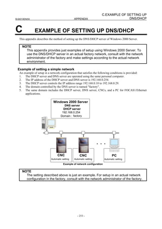
![C. EXAMPLE OF SETTING UP
DNS/DHCP APPENDIX B-64014EN/04
C.1 EXAMPLE OF SETTING UP DHCP SERVER OF Windows
2000 Server
1. Activating the Microsoft administrative console (DHCP)
Click [Programs] → [Administrative Tools] → [DHCP].
2. Adding a scope
Click [Action] → [New Scope] to start “New Scope Wizard”.
Click the [Next] button.
- 254 -](https://image.slidesharecdn.com/b-64014en04-121129012902-phpapp02/85/B-64014-en-04-266-320.jpg)
![C.EXAMPLE OF SETTING UP
B-64014EN/04 APPENDIX DNS/DHCP
Enter "factory" as [Name], and enter "FACTORY" as [Description].
Click the [Next] button.
Enter “192.168.0.10” as [Start IP address], enter “192.168.0.29” as [End IP address], enter “24” as
[Length], and enter “255.255.255.0” as [Subnet mask].
Click the [Next] button.
Click the [Next] button without entering any data.
- 255 -](https://image.slidesharecdn.com/b-64014en04-121129012902-phpapp02/85/B-64014-en-04-267-320.jpg)
![C. EXAMPLE OF SETTING UP
DNS/DHCP APPENDIX B-64014EN/04
Keep "8" days unchanged as Period, then click the [Next] button.
Keep [Yes, I want to configure these options now] selected, and click the [Next] button.
Click the [Next] button without entering any data.
Enter “192.168.0.254” as IP Address, then click [Add].
- 256 -](https://image.slidesharecdn.com/b-64014en04-121129012902-phpapp02/85/B-64014-en-04-268-320.jpg)
![C.EXAMPLE OF SETTING UP
B-64014EN/04 APPENDIX DNS/DHCP
Click the [Next] button.
Click the [Next] button without entering any data.
Keep [Yes, I want to activate this scope now] selected, and click the [Next] button.
- 257 -](https://image.slidesharecdn.com/b-64014en04-121129012902-phpapp02/85/B-64014-en-04-269-320.jpg)
![C. EXAMPLE OF SETTING UP
DNS/DHCP APPENDIX B-64014EN/04
Click [Finish].
3. Adding a scope option
Click [Scope[192.168.0.0]factory], then click [Scope Options] → [Action] → [Configure Options].
From the available options, find and check [DNS Domain Name]. Then, enter "factory" as String value.
Click the [OK] button.
The following setting is made:
- 258 -](https://image.slidesharecdn.com/b-64014en04-121129012902-phpapp02/85/B-64014-en-04-270-320.jpg)
![C.EXAMPLE OF SETTING UP
B-64014EN/04 APPENDIX DNS/DHCP
4. Enabling Dynamic DNS
Click [Scope[192.168.0.0]factory] → [Properties] → [DNS].
Check [Always update DNC] and [Enable updates for DNS clients that do not support dynamic update].
Click the [OK] button.
This completes DHCP server setting.
- 259 -](https://image.slidesharecdn.com/b-64014en04-121129012902-phpapp02/85/B-64014-en-04-271-320.jpg)
![C. EXAMPLE OF SETTING UP
DNS/DHCP APPENDIX B-64014EN/04
C.2 EXAMPLE OF SETTING UP DNS SERVER OF Windows
2000 Server
1. Activating the Microsoft administrative console (DNS)
Click [Programs] → [Administrative Tools] → [DNS].
2. DNS server configuration
Click [Action] → [Configure the server] to start [Configure DNS Server Wizard].
Click the [Next] button.
- 260 -](https://image.slidesharecdn.com/b-64014en04-121129012902-phpapp02/85/B-64014-en-04-272-320.jpg)
![C.EXAMPLE OF SETTING UP
B-64014EN/04 APPENDIX DNS/DHCP
Keep [This is the first DNS server on this network] selected, and click the [Next] button.
Keep [Yes, create a forward lookup zone], and click the [Next] button.
Keep [Standard primary] selected, and click the [Next] button.
Enter "factory." as Name. (Do not fail to enter "." after "factory".)
Click the [Next] button.
- 261 -](https://image.slidesharecdn.com/b-64014en04-121129012902-phpapp02/85/B-64014-en-04-273-320.jpg)
![C. EXAMPLE OF SETTING UP
DNS/DHCP APPENDIX B-64014EN/04
Keep “factory.dns” unchanged, and click the [Next] button.
Keep [Yes, create a reverse lookup zone] selected, and click the [Next] button.
Keep [Standard primary] selected, and click the [Next] button.
Enter “192.168.0” as Network ID.
- 262 -](https://image.slidesharecdn.com/b-64014en04-121129012902-phpapp02/85/B-64014-en-04-274-320.jpg)
![C.EXAMPLE OF SETTING UP
B-64014EN/04 APPENDIX DNS/DHCP
Click the [Next] button.
Keep “0.168.192.in-addr.arpa.dns” unchanged, and click the [Next] button.
Click the [Finish] button.
- 263 -](https://image.slidesharecdn.com/b-64014en04-121129012902-phpapp02/85/B-64014-en-04-275-320.jpg)
![C. EXAMPLE OF SETTING UP
DNS/DHCP APPENDIX B-64014EN/04
3. Enabling Dynamic DNS
Right-click [Forward Lookup Zones] → [factory].
Click [Properties].
For [Allow dynamic updates?], select [Yes].
Click the [OK] button.
This completes DNS server setting.
- 264 -](https://image.slidesharecdn.com/b-64014en04-121129012902-phpapp02/85/B-64014-en-04-276-320.jpg)
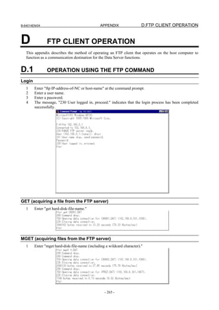
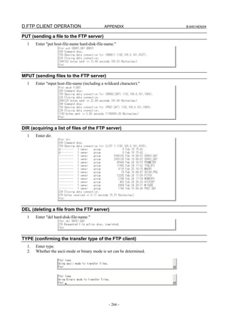
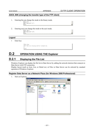
![D.FTP CLIENT OPERATION APPENDIX B-64014EN/04
2. Select [Map Network Drive] in the submemu of [Tools] on the menu bar.
3. Click “Create a shortcut to a Web folder or FTP site.” to start “Add Network Place Wizard”.
4. Input the user name, the password, and the IP address of Data Server for logging in to Data Server,
then click [Next]. The format is “ftp://[user name]:[password]@[IP address of Data Server]”.
- 268 -](https://image.slidesharecdn.com/b-64014en04-121129012902-phpapp02/85/B-64014-en-04-280-320.jpg)
![B-64014EN/04 APPENDIX D.FTP CLIENT OPERATION
5. Input the name for Data Server, then click [Finish].
6. The file list in Data Server can be displayed by the Explorer.
The icon of Data Server is added in My Network Places. For the next time, the file list in Data
Server can be displayed by double-clicking this icon.
- 269 -](https://image.slidesharecdn.com/b-64014en04-121129012902-phpapp02/85/B-64014-en-04-281-320.jpg)
![D.FTP CLIENT OPERATION APPENDIX B-64014EN/04
Register Data Server as a Network Place (for Windows XP Professional)
1. Start an Explorer.
2. Select [Map Network Drive] in the submemu of [Tools] on the menu bar.
- 270 -](https://image.slidesharecdn.com/b-64014en04-121129012902-phpapp02/85/B-64014-en-04-282-320.jpg)
![B-64014EN/04 APPENDIX D.FTP CLIENT OPERATION
3. Click “Sign up for online storage or connect to a network server.” to start “Add Network Place
Wizard”. Next, click [Next].
4. Select “Choose another network location”, then click [Next].
- 271 -](https://image.slidesharecdn.com/b-64014en04-121129012902-phpapp02/85/B-64014-en-04-283-320.jpg)
![D.FTP CLIENT OPERATION APPENDIX B-64014EN/04
5. Input the user name, the password, and the IP address of Data Server for logging in to Data Server,
then click [Next]. The format is “ftp://[user name]:[password]@[IP address of Data Server]”.
6. Input the name for Data Server, then click [Next].
- 272 -](https://image.slidesharecdn.com/b-64014en04-121129012902-phpapp02/85/B-64014-en-04-284-320.jpg)
![B-64014EN/04 APPENDIX D.FTP CLIENT OPERATION
7. Click [Finish].
8 Check [Enable folder view for FTP sites] in Internet Options as follows. (This item is checked by
default.)
- 273 -](https://image.slidesharecdn.com/b-64014en04-121129012902-phpapp02/85/B-64014-en-04-285-320.jpg)
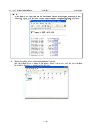
![B-64014EN/04 APPENDIX D.FTP CLIENT OPERATION
Register Data Server as a Network Location (for Windows Vista Business or
Windows 7 Professional)
1. Start an Explorer.
2. Display the menu of [Organize], then check [Menu Bar] in [Layout] to display the menu bar.
- 275 -](https://image.slidesharecdn.com/b-64014en04-121129012902-phpapp02/85/B-64014-en-04-287-320.jpg)
![D.FTP CLIENT OPERATION APPENDIX B-64014EN/04
3. Select [Map Network Drive] in the submemu of [Tools] on the menu bar.
4. Click “Connect to a Web site that you can use to store your documents and pictures.” to start “Add
Network Location”. Next, click [Next].
- 276 -](https://image.slidesharecdn.com/b-64014en04-121129012902-phpapp02/85/B-64014-en-04-288-320.jpg)
![B-64014EN/04 APPENDIX D.FTP CLIENT OPERATION
5. Select “Choose a custom network location”, then click [Next].
6. Input the user name, the password, and the IP address of Data Server for logging in to Data Server,
then click [Next]. The format is “ftp://[user name]:[password]@[IP address of Data Server]”.
- 277 -](https://image.slidesharecdn.com/b-64014en04-121129012902-phpapp02/85/B-64014-en-04-289-320.jpg)
![D.FTP CLIENT OPERATION APPENDIX B-64014EN/04
7. Input the name for Data Server, then click [Next].
8. Click [Finish].
- 278 -](https://image.slidesharecdn.com/b-64014en04-121129012902-phpapp02/85/B-64014-en-04-290-320.jpg)
![B-64014EN/04 APPENDIX D.FTP CLIENT OPERATION
9. The file list in Data Server can be displayed by the Explorer.
The icon of Data Server is added in Computer. For the next time, the file list in Data Server can be
displayed by double-clicking this icon.
NOTE
1 If Work Offline is run in Internet Explorer, when the file list in Data Server attempt
to be displayed by the Explorer, the error shown below occurs.
In this case, it is necessary to stop Work Offline in Internet Explorer. Remove
check [Work Offline] in submenu of [File] on the menu bar in Internet Explorer.
2 Even if the file list in Data Server is changed by operating CNC, it is not
automatically updated in the Explorer. If the FTP communication with Data
Server is not performed for five minutes or more, Data Server disconnects the
FTP connection. Execute [Refresh] in the Explorer to acquire the latest file list in
Data Server.
- 279 -](https://image.slidesharecdn.com/b-64014en04-121129012902-phpapp02/85/B-64014-en-04-291-320.jpg)
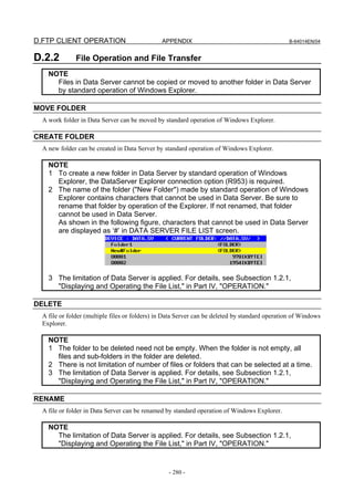
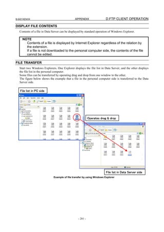
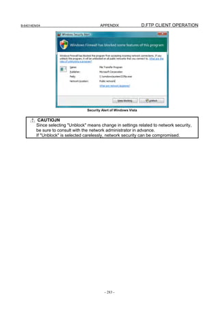


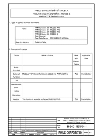
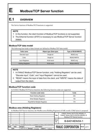
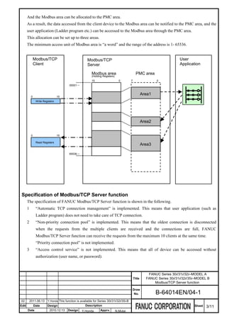
![E.2 SETTING THE Modbus/TCP SERVER FUNCTION
This chapter describes the communication setting for the Modbus/TCP Server function.
Notes on using the Modbus/TCP Server function
NOTE
1 The client of Modbus/TCP functions is not supported.
2 The number of Modbus/TCP clients that can be connected with one CNC is
maximum 10 at the same time. When more than ten connections are attempted,
the oldest communication is disconnected.
3 Please confirm that there is no problem as the entire system when
communicating with the device of the other companies.
E.2.1 SETTING THE Modbus/TCP SERVER FUNCTION
This section describes the setting screen for operating the Modbus/TCP Server function.
Procedure
1 Press function key .
2 Soft key [ETHER BOARD] ([ETHER NET] for the Series 30i/31i/32i/35i-B) appears. (When soft key
does not appear, press the continue key.)
3 Press soft key [ETHER BOARD] to display the Ethernet Setting screen.
4 Press soft keys [COMMON] and [Modbus SET], and then enter the parameters.
COMMON screen (BASIC)
Press soft key [COMMON] to display the COMMON screen (BASIC).
FANUC Series 30i/31i/32i–MODEL A
Title FANUC Series 30i/31i/32i/35i–MODEL B
Modbus/TCP Server function
Draw
No. B-64014EN/04-1
02 2011.06.13 Y.Honda This function is available for Series 30i/31i/32i/35i-B
Edit Date Design Description Sheet 4/11
Date 2010.12.13 Design Y.Honda Apprv. N.Mutai](https://image.slidesharecdn.com/b-64014en04-121129012902-phpapp02/85/B-64014-en-04-305-320.jpg)
![COMMON screen (BASIC)
Setting item
Item Description
IP ADDRESS Specify the IP address of the Fast Ethernet.
(Example of specification format "192.168.0.100")
SUBNET MASK Specify a mask address for the IP addresses of the network.
(Example of specification format "255.255.255.0")
ROUTER IP ADDRESS Specify the IP address of the router.
Specify this item when the network contains a router.
(Example of specification format "192.168.0.253")
Display item
Item Description
MAC ADDRESS MAC address of the Fast Ethernet
Modbus SERVER screens
Press soft key [Modbus SET] to display the Modbus SERVER screen.
FANUC Series 30i/31i/32i–MODEL A
Title FANUC Series 30i/31i/32i/35i–MODEL B
Modbus/TCP Server function
Draw
No. B-64014EN/04-1
02 2011.06.13 Y.Honda This function is available for Series 30i/31i/32i/35i-B
Edit Date Design Description Sheet 5/11
Date 2010.12.13 Design Y.Honda Apprv. N.Mutai](https://image.slidesharecdn.com/b-64014en04-121129012902-phpapp02/85/B-64014-en-04-306-320.jpg)
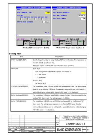
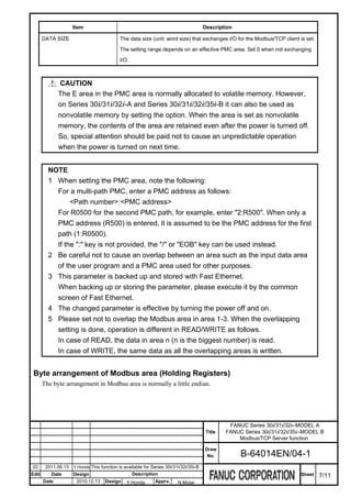
![On Ethernet line Modbus area PMC area
(Holding Registers)
0 15 15 0 7 0
+00 +00 +00
12h 34h 34h 12h 34h
+01 56h 78h +01 78h 56h +01 12h
+02 78h
+03 56h
When Bit0 of OPTION1 is "1", byte arrangement of data becomes a big endian.
On Ethernet line Modbus area PMC area
(Holding Registers)
0 15 0 15 7 0
+00 +00 +00
12h 34h 12h 34h 12h
+01 56h 78h +01 56h 78h +01 34h
+02 56h
+03 78h
Status
The status detected by Modbus/TCP Server function
STATUS
STATUS PMC ADDRESS Bit7 Bit6 Bit5 Bit4 Bit3 Bit2 Bit1 Bit0
Modbus status
Bit0 : The serious error was detected.
Bit1 - Bit5 : Reserved.
Bit6 : The initialization was completed.
Bit7 : Under communicating with one Modbus/TCP client or more.
E.2.2 MAINTENANCE SCREENS OF Modbus/TCP SERVER FUNCTION
The connection status of the client of Modbus/TCP can be confirmed on this screen.
Procedure
1 Press function key .
2 Soft key [ETHER BOARD] ([ETHER NET] for the Series 30i/31i/32i/35i-B) appears. (When soft key
does not appear, press the continue key.)
FANUC Series 30i/31i/32i–MODEL A
Title FANUC Series 30i/31i/32i/35i–MODEL B
Modbus/TCP Server function
Draw
No. B-64014EN/04-1
02 2011.06.13 Y.Honda This function is available for Series 30i/31i/32i/35i-B
Edit Date Design Description Sheet 8/11
Date 2010.12.13 Design Y.Honda Apprv. N.Mutai](https://image.slidesharecdn.com/b-64014en04-121129012902-phpapp02/85/B-64014-en-04-309-320.jpg)
![3 Press soft key [ETHER BOARD] to display the Ethernet Setting screen.
4 Press soft key [Modbus MAINTE], and then Modbus SERVER MAINTENANCE screen (CLIENT LIST)
is displayed.
Modbus/TCP SERVER MAINTENANCE screen (CLIENT LIST)
Display item
Item Description
CLIENT IP address of the Modbus/TCP client communicating with this Modbus/TCP Server is displayed.
(Example of display form "192.168.0.200")
It is displayed in order of communicating with this Server.
TIME The connecting time of the Modbus/TCP client communicating with this Server is displayed.
The displayed time is updated automatically.
The display form displays hour (hhh), minute (mm) and second (ss) in the form of "hhh:mm:ss". When
the maximum value is exceeded by "999: 59:59", the maximum value is not updated from "999: 59:59".
E.2.3 LOG SCREEN OF Modbus/TCP SERVER FUNCTION
The communication log related to Modbus/TCP Server function is displayed.
FANUC Series 30i/31i/32i–MODEL A
Title FANUC Series 30i/31i/32i/35i–MODEL B
Modbus/TCP Server function
Draw
No. B-64014EN/04-1
02 2011.06.13 Y.Honda This function is available for Series 30i/31i/32i/35i-B
Edit Date Design Description Sheet 9/11
Date 2010.12.13 Design Y.Honda Apprv. N.Mutai](https://image.slidesharecdn.com/b-64014en04-121129012902-phpapp02/85/B-64014-en-04-310-320.jpg)
![LOG screen for Modbus/TCP Server function
Procedure
1 Press function key .
2 Press soft key [BOARD LOG] ([ETHER LOG] for the Series 30i/31i/32i/35i-B) to display the Ethernet
log screen. (When soft key does not appear, press the continue key.)
3 Press soft key [Modbus], and then the information related to the Modbus/TCP Server function is displayed.
Modbus/TCP LOG screen
The latest log information is displayed at the top of the screen. At the right end of a log item, the occurrence
date and time of the log item is indicated. Date and time data is indicated in the format “MMM.DD hh:mm:ss”,
where MMM represents a month, DD represents a day, hh represents hour, mm represents minute, and ss
represents second.
The top item in the example above indicates “22:32:47 on September 10”.
To clear the log information, press soft key [(OPRT)] then soft key [CLEAR].
NOTE
The Modbus/TCP Server log information is stored in volatile memory and it is lost
when the power of CNC is turned off. Check the log information when an error
occurs.
FANUC Series 30i/31i/32i–MODEL A
Title FANUC Series 30i/31i/32i/35i–MODEL B
Modbus/TCP Server function
Draw
No. B-64014EN/04-1
02 2011.06.13 Y.Honda This function is available for Series 30i/31i/32i/35i-B
Edit Date Design Description Sheet 10/11
Date 2010.12.13 Design Y.Honda Apprv. N.Mutai](https://image.slidesharecdn.com/b-64014en04-121129012902-phpapp02/85/B-64014-en-04-311-320.jpg)
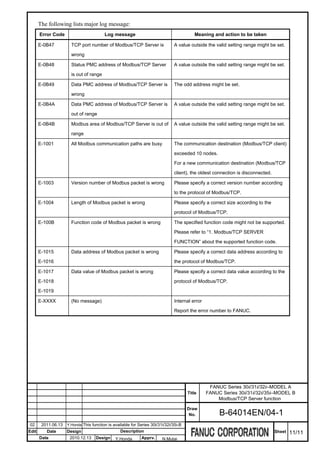
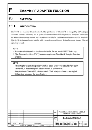
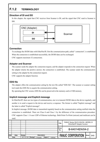
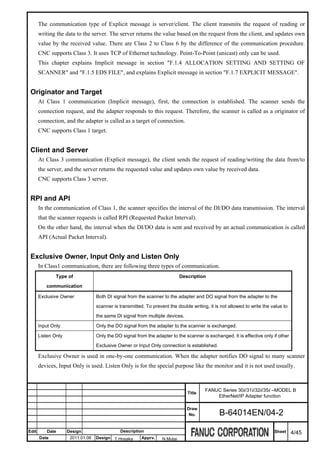
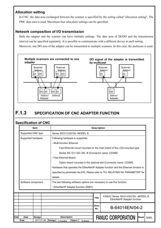
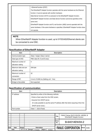
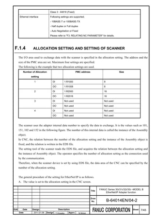
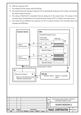
![NOTE
1 In this chapter, the procedures of A and B in the figure are explained. Please refer
to the manual of the scanner device for the procedure from C to E.
2 If either of the following case is applied, it is necessary to specify the instance of
the Assembly object corresponding to the allocation setting of CNC at the
scanner or the setting tool of the scanner.
- The scanner is set without using EDS file.
- Class 3 communication is executed to CNC.
3 Please refer to "F.6.1 SUPPORTED CLASS AND INSTANCE" for details of the
instance of the Assembly object.
F.1.5 EDS FILE
The setting of the connection that is acceptable by the adapter is described in EDS file with text format.
By operating the CNC screen, EDS file is output to the memory card or the USB memory.
Type
There are following two types in EDS file.
Type How to create Description
Standard EDS file Output EDS file after all EDS file that can be used for the general purpose
allocation settings are disabled. The content of the allocation setting is not reflected.
EDS file corresponding to Output EDS file after at least EDS file where the content of the allocation setting is
the allocation setting one allocation setting is reflected
enabled. Items to set in the setting tool of the scanner are few and
the setting is easy.
Contents of EDS file
The contents other than the setting of the connection are the same between the standard EDS file and the EDS
file corresponding to the allocation setting. This section explains the setting of the connection.
Standard EDS file
The setting of the following connections is preserved regardless of the content of the allocation setting of CNC.
[Four Allocation Settings : No.01 to No.04] *
[Three types of communication : Exclusive Owner, Input Only and Listen Only]
= Total 12 types
The DI/DO data size is not preserved in EDS file.
FANUC Series 30i/31i/32i/35i –MODEL B
Title
EtherNet/IP Adapter function
Draw
No. B-64014EN/04-2
Edit Date Design Description Sheet 9/45
Date 2011.01.06 Design T.Hosaka Apprv. N.Mutai](https://image.slidesharecdn.com/b-64014en04-121129012902-phpapp02/85/B-64014-en-04-321-320.jpg)
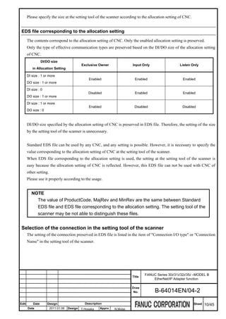
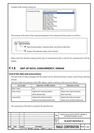
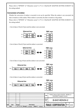

![F.2.2 SCREEN LAYOUT
The kind of the hardware that is used by EtherNet/IP Adapter function is shown on the title bar of each screen.
Title Description
Fast Ethernet circuit mounted on the main board of the LCD-mounted type
[MULTI-FUNC ETHER]
Series 30i/31i/32i /35i -B
[BOARD(SLOT1)] Option board mounted in the optional slot 1
[BOARD(SLOT2)] Option board mounted in the optional slot 2
[BOARD(SLOT3)] Option board mounted in the optional slot 3
[BOARD(SLOT4)] Option board mounted in the optional slot 4
F.2.3 EtherNet/IP ADAPTER SETTING SCREEN
EtherNet/IP Adapter setting screen consists of the basic screen (page 1) and the allocation screens (page 2 to 5).
A common setting to EtherNet/IP Adapter function is specified on the basic screen.
A setting for each allocation setting is specified on allocation screens.
FANUC Series 30i/31i/32i/35i –MODEL B
Title
EtherNet/IP Adapter function
Draw
No. B-64014EN/04-2
Edit Date Design Description Sheet 15/45
Date 2011.01.06 Design T.Hosaka Apprv. N.Mutai](https://image.slidesharecdn.com/b-64014en04-121129012902-phpapp02/85/B-64014-en-04-327-320.jpg)
![NOTE
1 Before changing a parameter on the EtherNet/IP Adapter setting screen, set the
MDI mode or emergency stop state.
2 If the Change protection level of the Ethernet function is higher than the Operation
level in 8-level data protection function, it is not possible to change the settings.
Procedure
1 Press function key .
2 Soft key [ETHERNET] appears. (When soft key does not appear, press the continue key.)
3 Press soft key [ETHERNET] to display Ethernet Setting screen.
4 Press soft key [EIP A SET]. (When soft key does not appear, press the continue key.)
5 Press Page key to switch the page, and then enter the parameters.
Basic screen
1st page is basic screen. A common setting in the EtherNet/IP Adapter function is done.
EtherNet/IP Adapter setting screen (Basic)
Press soft key [(OPRT)] as needed and then use the following soft keys.
[DI DATA] :
FANUC Series 30i/31i/32i/35i –MODEL B
Title
EtherNet/IP Adapter function
Draw
No. B-64014EN/04-2
Edit Date Design Description Sheet 16/45
Date 2011.01.06 Design T.Hosaka Apprv. N.Mutai](https://image.slidesharecdn.com/b-64014en04-121129012902-phpapp02/85/B-64014-en-04-328-320.jpg)
![Setting item
Item Description
Specify the operation when the update of DI area stops.
HOLD : DI area is held. (Nothing is done).
DI DATA ON
CLEAR : DI area is cleared to be zero.
ABNORMAL
Soft key is used to change the setting. Press Soft key [(OPRT)], [DI DATA], and then select [HOLD]
or [CLEAR].
Specify the top address in the R/E/D area of PMC where the status of EtherNet/IP Adapter function
is stored.
STATUS
When status is not used, set " " (blank). "---" is displayed in STATUS ADDRESS and "0" is displayed
ADDRESS
in STATUS SIZE.
The setting range depends on an effective PMC area. It depends on the value of STATUS SIZE too.
Specify the size of PMC area where status is stored. The content of status that is output to PMC
area is limited according to this size.
STATUS SIZE When status is not used, set "0". "---" is displayed in STATUS ADDRESS and "0" is displayed in
STATUS SIZE.
The setting range is either 0, 1 or 3.
Bit 0-1 : These bits specify the operation when IP address, subnet mask, router IP address, DNS IP
address 1 and 2 and domain are acquired from DHCP server by using DHCP client function
(No.904#6).
Bit 0 : Parameters acquired by DHCP client function are
0 : not saved in nonvolatile memory (SRAM).
1 : saved in nonvolatile memory . When succeeding in saving, Bit 1 is automatically set to 1.
Bit 1 : DHCP client function is
0 : enabled.
OPTION 1
1 : disabled. (It is not possible to set this bit manually.)
Bit 2-4 : Reserved (Must be zero)
Bit 7 : EtherNet/IP function is
0 : enabled.
1 : disabled.
When disabled, the communication is not done. And in the maintenance screen, the indicators
of MS and NS turn off, and the value zero is displayed in all items from VENDOR ID to SERIAL
NO.
Bit 0 : When the power supply is turned on next time, the setting of EtherNet/IP is
OPTION 2 0 : not initialized.
1 : initialized.
FANUC Series 30i/31i/32i/35i –MODEL B
Title
EtherNet/IP Adapter function
Draw
No. B-64014EN/04-2
Edit Date Design Description Sheet 17/45
Date 2011.01.06 Design T.Hosaka Apprv. N.Mutai](https://image.slidesharecdn.com/b-64014en04-121129012902-phpapp02/85/B-64014-en-04-329-320.jpg)
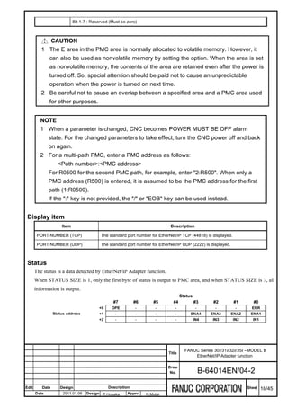
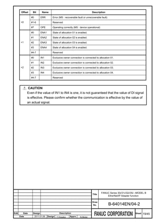
![Allocation screen
Page 2 to 5 is allocation screen. Page 2 to 5 corresponds to allocation 01 to 04.
EtherNet/IP Adapter setting screen (Allocation)
Press soft key [(OPRT)] as needed and then use the following soft keys.
[STATE] :
FANUC Series 30i/31i/32i/35i –MODEL B
Title
EtherNet/IP Adapter function
Draw
No. B-64014EN/04-2
Edit Date Design Description Sheet 20/45
Date 2011.01.06 Design T.Hosaka Apprv. N.Mutai](https://image.slidesharecdn.com/b-64014en04-121129012902-phpapp02/85/B-64014-en-04-332-320.jpg)
![Setting item
Item Description
Specify whether the allocation is used or not.
ENABLE : This allocation is used.
DISABLE : This allocation is not used.
If STATE is “ENABLE”, the setting can not be changed. When trying to change the setting, the
message "Change ENABLE into DISABLE" is displayed.
To change the setting, first set the item STATE to be "DISABLE". When the change is completed,
STATE set the item STATE to be "ENABLE".
When the item STATE is changed to "ENABLE", the conformance of the setting is confirmed. If
there is a problem, the message is displayed and item STATE keeps "DISABLE".
Moreover, when NC stands up, the conformance of the setting is confirmed. If there is a problem,
item STATE is changed to "DISABLE" automatically.
Soft key is used for setting. Press Soft key [(OPRT)], [STATE], and then select [ENABLE] or
[DISABLE].
Specify the type of area where DI/DO data is stored.
0 : DI/DO data is not used.
1 : DI/DO data is allocated to PMC area.
TYPE
When the item TYPE is changed, ADDRESS is cleared to "---" and SIZE is cleared to zero.
If " "(Space) is set to ADDRESS or "0" is set to SIZE, "0" is displayed in TYPE, "---" is displayed in
ADDRESS and "0" is displayed to SIZE. The setting becomes unused.
Specify the address of the area where DI/DO data is stored.
When the item TYPE is "0", the value cannot be set.
ADDRESS When the item TYPE is "1", the top address of PMC area is set. R, D or E area can be specified.
The setting range depends on the actual range of R area, E area, and D area of PMC.
It is necessary to set the area specified by ADDRESS and SIZE within the range of PMC area.
Specify the size of area where DI/DO data is stored.
When TYPE is “0”, the value can not be set.
SIZE When TYPE is "1", the size of PMC area is set.
The range is 1 to 256 (byte).
It is necessary to set the area specified by ADDRESS and SIZE within the range of PMC area.
Bit 0 : Unit of data is Word (2 byte).
0 : Disabled
1 : Enabled
OPTION
When enabled, both ADDREE and SIZE must be aligned with 2-byte boundaries.
Example) ADDRESS / SIZE = R1000/2, R1002/4, E1004/6
Bit 1 : Unit of data is Long (4 byte).
FANUC Series 30i/31i/32i/35i –MODEL B
Title
EtherNet/IP Adapter function
Draw
No. B-64014EN/04-2
Edit Date Design Description Sheet 21/45
Date 2011.01.06 Design T.Hosaka Apprv. N.Mutai](https://image.slidesharecdn.com/b-64014en04-121129012902-phpapp02/85/B-64014-en-04-333-320.jpg)
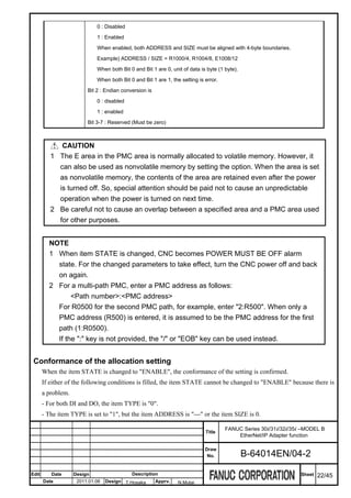
![- The range of DI/DO area is out of PMC area.
- OPTION Bit 0 and Bit 1 are both set to "1".
- OPTION Bit 0 is set to "1", but the unit of the item ADDRESS or SIZE is not aligned with 2-byte boundaries.
- OPTION Bit 0 is set to "1", but the unit of the item ADDRESS or SIZE is not aligned with 4-byte boundaries.
F.2.4 BACKING UP AND RESTORING SETTING
This section explains how to back up or restore the setting of EtherNet/IP Adapter function.
The setting can be preserved in the memory card or USB memory.
When backing up and restoring the setting of the EtherNet/IP Adapter function, the communication parameters
of the Ethernet function is backed up and restored too.
Procedure
1 Press function key .
2 Soft key [ETHERNET] appears. (When soft key does not appear, press the continue key.)
3 Press soft key [ETHERNET] to display Ethernet Setting screen.
4 Press soft key [EIP A SET]. (When soft key does not appear, press the continue key.)
5 Press soft key [(OPRT)], and then [+]. The soft keys [BACKUP], [RESTORE], [ALL BACKUP], and
[ALL RESTORE] for backing up or restoring settings appear.
6 Press the soft key [BACKUP], [RESTORE], [ALL BACKUP], or [ALL RESTORE]. The soft keys
[EXECUTE] and [CANCEL] appear.
7 Enter the name of a file to be backed up or restored in the key-in buffer, and press the soft key
[EXECUTE]. The operation selected at the above step is executed.
The character string “EXECUTING” blinks during execution.
FANUC Series 30i/31i/32i/35i –MODEL B
Title
EtherNet/IP Adapter function
Draw
No. B-64014EN/04-2
Edit Date Design Description Sheet 23/45
Date 2011.01.06 Design T.Hosaka Apprv. N.Mutai](https://image.slidesharecdn.com/b-64014en04-121129012902-phpapp02/85/B-64014-en-04-335-320.jpg)
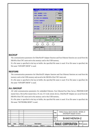
![ALL RESTORE
All valid communication parameters for embedded Ethernet, Fast Ethernet/Fast Data Server, PROFIBUS-DP
master/slave, DeviceNet master/slave, FL-net, CC-Link remote device and EtherNet/IP adapter are read from
the memory card or the USB memory and saved to the SRAM of the CNC main unit.
However, if a communication function related to a valid communication parameter is disabled in the CNC, that
parameter is not saved to the SRAM.
If a file name is specified in the key-in buffer, the specified file name is used. If no file name is specified, the
file name “NETWORK.MEM” is used.
CAUTION
While an external input/output device such as the memory card or USB memory is
being accessed, do not turn the power to the CNC off or remove the external
input/output device. Doing so may damage the external input/output device.
NOTE
1 A backup or restore operation for communication parameters can only be
performed in the MDI mode, EDIT mode, or emergency stop state.
2 When communication parameters are restored, an alarm condition occurs that
requires power-off.
3 When the 8-level data protection function is enabled, whether back up or restore of
the communication parameter for Ethernet function and EtherNet/IP Adapter
function is allowed or not depends on the setting of that function.
Related NC parameter
0020 I/O CHANNEL: Input/output device selection, or interface number for a foreground
0020
input/output device
[Input type] Setting input
[Data type] Byte
[Valid data range] 4: Selects the memory card as the input/output device.
17: Selects the USB memory as the input/output device.
It is not possible to backup and restore the communication parameters by using other devices.
F.2.5 OUTPUT OF EDS FILE
This chapter explains the method of outputting the EDS file to the memory card or the USB memory.
FANUC Series 30i/31i/32i/35i –MODEL B
Title
EtherNet/IP Adapter function
Draw
No. B-64014EN/04-2
Edit Date Design Description Sheet 25/45
Date 2011.01.06 Design T.Hosaka Apprv. N.Mutai](https://image.slidesharecdn.com/b-64014en04-121129012902-phpapp02/85/B-64014-en-04-337-320.jpg)
![If the state of all allocation setting is disable, the standard EDS file is stored. If at least one of the allocation
setting is enable, EDS file corresponding to the allocation setting is stored.
Procedure
1 Press function key .
2 Soft key [ETHERNET] appears. (When soft key does not appear, press the continue key.)
3 Press soft key [ETHERNET] to display Ethernet Setting screen.
4 Press soft key [EIP A SET]. (When soft key does not appear, press the continue key.)
5 Press soft key [(OPRT)], and then [+]. The soft key [EDS OUTPUT] appears.
6 Press the soft key [EDS OUTPUT]. The soft keys [EXECUTE] and [CANCEL] appear.
7 Enter the file name of EDS file in the key-in buffer, and press the soft key [EXECUTE] to output EDS file.
If the file name is not specified, the file name “F_CNC101.EDS” is used.
The character string “EXECUTING” blinks during execution.
CAUTION
While an external input/output device such as the memory card or USB memory is
being accessed, do not turn the power to the CNC off or remove the external
input/output device. Doing so may damage the external input/output device.
FANUC Series 30i/31i/32i/35i –MODEL B
Title
EtherNet/IP Adapter function
Draw
No. B-64014EN/04-2
Edit Date Design Description Sheet 26/45
Date 2011.01.06 Design T.Hosaka Apprv. N.Mutai](https://image.slidesharecdn.com/b-64014en04-121129012902-phpapp02/85/B-64014-en-04-338-320.jpg)
![NOTE
1 Output of EDS file can only be performed in the MDI mode or EDIT mode.
2 When the 8-level data protection function is enabled, whether output of EDS file is
allowed or not depends on the setting of that function.
Related NC parameter
0020 I/O CHANNEL: Input/output device selection, or interface number for a foreground
0020
input/output device
[Input type] Setting input
[Data type] Byte
[Valid data range] 4: Selects the memory card as the input/output device.
17: Selects the USB memory as the input/output device.
It is not possible to backup and restore the communication parameters by using other devices.
F.2.6 EtherNet/IP ADAPTER MAINTENANCE SCREEN
EtherNet/IP adapter maintenance screen consists of the adapter information screen (page 1), scanner list screens
(page 2 to 5) and scanner detail screen.
Adapter information screen shows the information about LED display of MS and NS, and information of the
adapter such as Vendor ID, Device Type, and so on.
Scanner list screen shows the list of connected scanners.
Scanner detail screen shows the detailed information like RPI and API for the selected scanner.
Procedure
1 Press function key .
2 Soft key [ETHERNET] appears. (When soft key does not appear, press the continue key.)
3 Press soft key [ETHERNET] to display Ethernet Setting screen.
4 Press soft key [EIP A MAINTE]. (When soft key does not appear, press the continue key.)
5 Press Page key to switch the page.
FANUC Series 30i/31i/32i/35i –MODEL B
Title
EtherNet/IP Adapter function
Draw
No. B-64014EN/04-2
Edit Date Design Description Sheet 27/45
Date 2011.01.06 Design T.Hosaka Apprv. N.Mutai](https://image.slidesharecdn.com/b-64014en04-121129012902-phpapp02/85/B-64014-en-04-339-320.jpg)
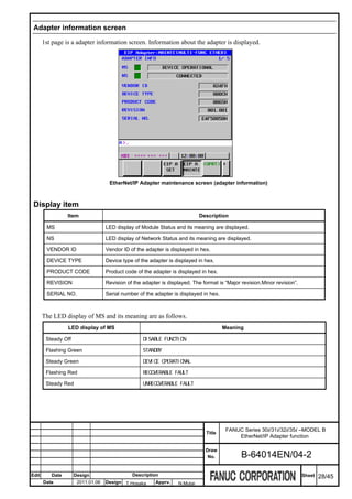
![The LED display of NS and its meaning is as follows.
LED display of NS Meaning
Steady Off (MS is steady off too) ---
Steady Off NO IP ADDRESS
Flashing Green NO CONNECTIONS
Steady Green CONNECTED
Flashing Red CONNECTION TIMEOUT
Steady Red DUPLICATE IP ADDRESS
Scanner list screen
Page 2 to 5 is a scanner list screen. Scanner currently connected is displayed.
EtherNet/IP Adapter maintenance screen (scanner list)
Press soft key [(OPRT)] as needed and then use the following soft keys.
Display item
Item Description
IP address of the scanner now connecting to the adapter is displayed in the list.
The scanner displayed in the list can be filtered by the allocation setting.
SCANNER LIST Press soft key [(OPRT)], and then [FILTER].
If the soft key [FILTER] is pressed, the end of the title changes as follows.
[ALL] -> [ALLOCATION01]->[ALLOCATION02]->[ALLOCATION03]->[ALLOCATION04]->[ALL]->
FANUC Series 30i/31i/32i/35i –MODEL B
Title
EtherNet/IP Adapter function
Draw
No. B-64014EN/04-2
Edit Date Design Description Sheet 29/45
Date 2011.01.06 Design T.Hosaka Apprv. N.Mutai](https://image.slidesharecdn.com/b-64014en04-121129012902-phpapp02/85/B-64014-en-04-341-320.jpg)
![Only the scanner connected with the allocation setting of the title is displayed in the list.
The connection type Explicit Message is displayed in [ALL].
IP ADDRESS IP address of the connected scanner is displayed.
The time connected with the scanner is displayed in the form of HHH:MM:SS.
TIME
When connect time exceeds 999:59:59, the display is not updated as 999:59:59.
Scanner detail screen
Procedure
1 On a scanner list screen, move the cursor to select the scanner for detail display.
2 Press soft key [(OPRT)], and then [DETAIL]. The scanner detail screen is displayed.
3 To return to the scanner list screen, press soft key [LIST].
EtherNet/IP Adapter maintenance screen (scanner detail)
Display item
Item Description
IP address of the scanner is displayed.
When the connection is lost while displaying this scanner detail screen, the message "Disconnected"
IP ADDRESS
is displayed beside the IP address. In this case, the value of each item is not updated. Please return
to the list, and select the scanner again.
TIME It is the same as the item TIME in the scanner list screen.
ALLOCATION The number of the allocation that is used in the connection of the scanner is displayed.
It is a sending and receiving interval of the DI/DO data that the scanner requested to EtherNet/IP
RPI (ms)
adapter.
FANUC Series 30i/31i/32i/35i –MODEL B
Title
EtherNet/IP Adapter function
Draw
No. B-64014EN/04-2
Edit Date Design Description Sheet 30/45
Date 2011.01.06 Design T.Hosaka Apprv. N.Mutai](https://image.slidesharecdn.com/b-64014en04-121129012902-phpapp02/85/B-64014-en-04-342-320.jpg)
![O=>T (Originator => Target) means DI data receive interval (scanner => adapter ).
T=>O (Target => Originator) means DO data send interval (adapter => scanner).
It is a sending and receiving interval of the DI/DO data that the EtherNet/IP Adapter function actually
API (ms) processed.
O=>T means DI data receive interval, and T=>O means DO data send interval.
It is a number of packets that the adapter function normally received.
RECV
The range is from 0 to 65535. The value returns to 0 when it exceeds 65535.
It is a number of packets that were not able to receive by the adapter function.
LOST
The range is from 0 to 65535. The value returns to 0 when it exceeds 65535.
It is a number of packets that the adapter function normally sent.
SEND
The range is from 0 to 65535. The value returns to 0 when it exceeds 65535.
F.2.7 EtherNet/IP ADAPTER FUNCTION LOG SCREEN
The log screen shows the log data about EtherNet/IP Adapter function.
Procedure
1 Press function key .
2 Press soft key [ETHER LOG] to display the Ethernet log screen. (When soft key does not appear, press the
continue key.)
3 Press soft key [EIP ADAPT], and then the information related to the EtherNet/IP Adapter function is
displayed.
EtherNet/IP Adapter function log screen
FANUC Series 30i/31i/32i/35i –MODEL B
Title
EtherNet/IP Adapter function
Draw
No. B-64014EN/04-2
Edit Date Design Description Sheet 31/45
Date 2011.01.06 Design T.Hosaka Apprv. N.Mutai](https://image.slidesharecdn.com/b-64014en04-121129012902-phpapp02/85/B-64014-en-04-343-320.jpg)
![The latest log information is displayed at the top of the screen. At the right end of a log item, the occurrence
date and time of the log item is indicated. Date and time data is indicated in the format “MMM.DD hh:mm:ss”,
where MMM represents a month, DD represents a day, hh represents hour, mm represents minute, and ss
represents second.
To clear the log information, press soft key [(OPRT)] then soft key [CLEAR].
NOTE
The log information of EtherNet/IP Adapter function is stored in volatile memory
and it is lost when the power of CNC is turned off. Check the log information when
an error occurs.
The following lists major log message:
Error Code Log message Meaning and action to be taken
E-1107 EtherNet/IP function and FL-net function cannot It is specified that the EtherNet/IP function and
be used at the same time the FL-net function are operated with the same
hardware.
Please confirm the value of parameter No.970,
971, and 972.
E-1109 All Connections of EtherNet/IP Adapter are busy Connections of the maximum number have
already been made.
The connection cannot be established exceeding
the maximum number.
E-110A Connect Request from EtherNet/IP Scanner is The unacceptable connection request was
refused received from the scanner.
E-110B Connect Request from EtherNet/IP Scanner is The unacceptable connection request was
refused (RPI Error) received from the scanner.
RPI specified from the scanner is beyond the
limits of value (4-10,000ms) that can be
accepted.
E-110C Connect Request from EtherNet/IP Scanner is The unacceptable connection request was
refused (DI/DO Size Error) received from the scanner.
The size of DI or DO specified from the scanner
is different from the size specified by the
allocation setting..
FANUC Series 30i/31i/32i/35i –MODEL B
Title
EtherNet/IP Adapter function
Draw
No. B-64014EN/04-2
Edit Date Design Description Sheet 32/45
Date 2011.01.06 Design T.Hosaka Apprv. N.Mutai](https://image.slidesharecdn.com/b-64014en04-121129012902-phpapp02/85/B-64014-en-04-344-320.jpg)
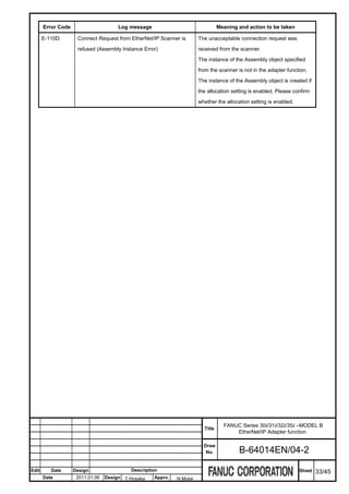
![F.3 RELATING NC PARAMETER
NC parameter related to EtherNet/IP Adapter function is as follows.
#7 #6 #5 #4 #3 #2 #1 #0
907 100 FUL FIX
NOTE
When this parameter is set, the power must be turned off before operation is
continued.
[Input type] Parameter input
[Data type] Bit
#0 FIX : In EtherNet/IP Adapter function, the auto-negotiation of Ethernet communication is
0 : valid. (10Mbps/100Mbps and full duplex/half duplex is distinguished automatically.)
1 : invalid. (The setting is specified by the following parameters, #1 FUL and #2 100.)
#1 FUL : In EtherNet/IP Adapter function, the communication of Ethernet is
0 : Half-duplex.
1 : Full-duplex
This bit is effective only if #0 FIX is 1.
#2 100 : In EtherNet/IP Adapter function, the transmission rate of Ethernet is
0 : 10Mbps
1 : 100Mbps
This bit is effective only if #0 FIX is 1.
0970 Select hardware that operates Ethernet or Data Server function
0971 Select hardware that operates first FL-net function
0972 Select hardware that operates second FL-net function
NOTE
When this parameter is set, the power must be turned off before operation is
continued.
[Input type] Parameter input
FANUC Series 30i/31i/32i/35i –MODEL B
Title
EtherNet/IP Adapter function
Draw
No. B-64014EN/04-2
Edit Date Design Description Sheet 34/45
Date 2011.01.06 Design T.Hosaka Apprv. N.Mutai](https://image.slidesharecdn.com/b-64014en04-121129012902-phpapp02/85/B-64014-en-04-346-320.jpg)
![[Data type] Byte
[Valid data range] -1 to 6
Hardware that operates each function is selected.
Value Hardware
-1 Not used
0 Unsetting
1 Multi-function Ethernet
2 (reserved)
3 Fast Ethernet board mounted in slot 1
4 Fast Ethernet board mounted in slot 2
5 Fast Ethernet board mounted in slot 3
6 Fast Ethernet board mounted in slot 4
NOTE
1. EtherNet/IP Adapter function operates with Ethernet function on the same
hardware that is specified by parameter No.970.
2. EtherNet/IP Adapter function cannot be operated on the same hardware as the
FL-net function. Therefore, parameter No.970 and No.971 or No.970 and No.972
cannot be set to the same value.
FANUC Series 30i/31i/32i/35i –MODEL B
Title
EtherNet/IP Adapter function
Draw
No. B-64014EN/04-2
Edit Date Design Description Sheet 35/45
Date 2011.01.06 Design T.Hosaka Apprv. N.Mutai](https://image.slidesharecdn.com/b-64014en04-121129012902-phpapp02/85/B-64014-en-04-347-320.jpg)
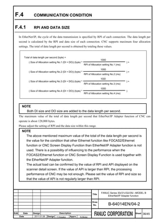
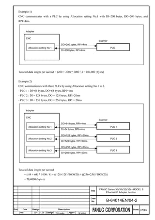
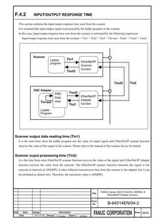
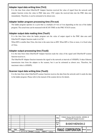
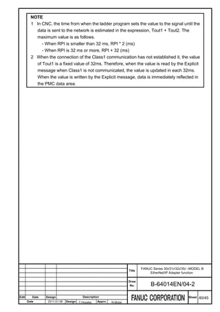
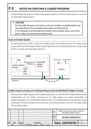
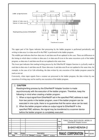
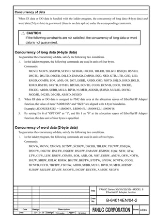
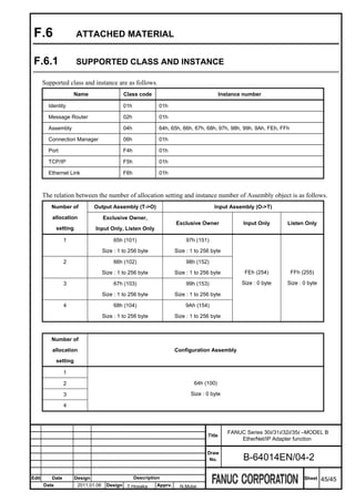
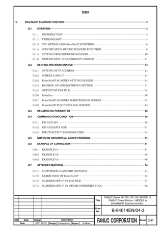
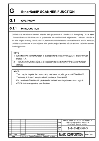
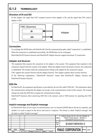
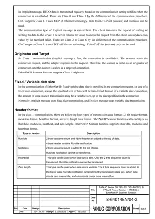
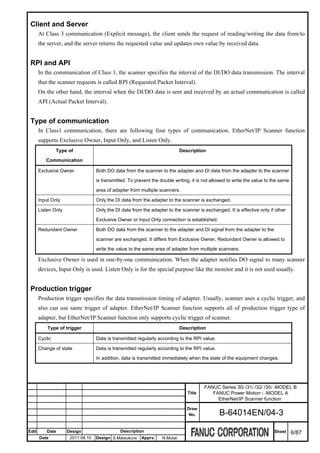
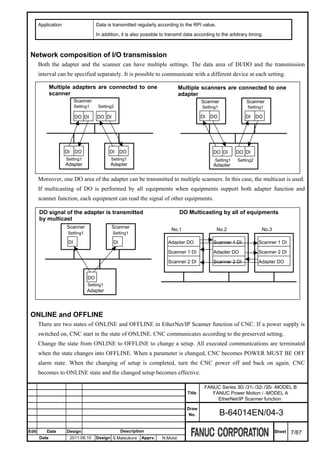
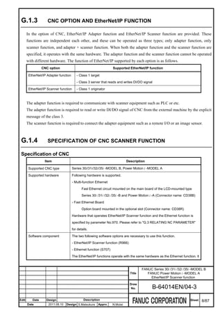
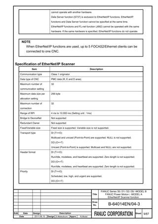
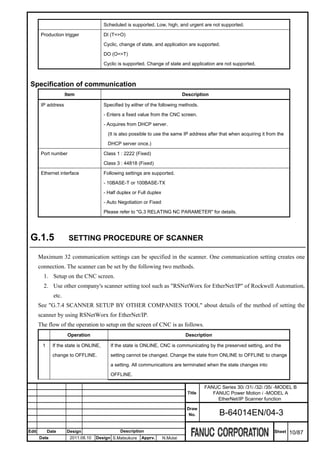
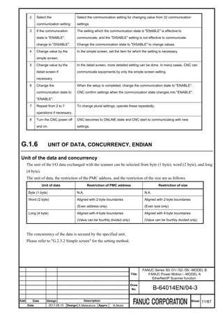
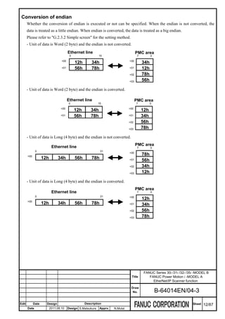
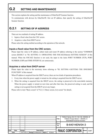
![G.2.2 SCREEN LAYOUT
The kind of the hardware that is used by EtherNet/IP Scanner function is shown on the title bar of each screen.
Title Description
Fast Ethernet circuit mounted on the main board of the LCD-mounted type
[MULTI-FUNC ETHER]
Series 30i/31i/32i/35i -B and Power Motion i -A
[BOARD(SLOT1)] Option board mounted in the optional slot 1
[BOARD(SLOT2)] Option board mounted in the optional slot 2
[BOARD(SLOT3)] Option board mounted in the optional slot 3
[BOARD(SLOT4)] Option board mounted in the optional slot 4
G.2.3 EtherNet/IP SCANNER SETTING SCREEN
This section explains setting screens for the operation of EtherNet/IP Scanner function. Setting screens consists
of the following screens.
Basic screen 1/2
List screen 2/2 Simple screen 1/2, 2/2 Detail screen 1/4 - 4/4
Consist of setting screens of EtherNet/IP Scanner function
FANUC Series 30i /31i /32i /35i -MODEL B
Title FANUC Power Motion i -MODEL A
EtherNet/IP Scanner function
Draw
No. B-64014EN/04-3
Edit Date Design Description Sheet 14/87
Date 2011.08.10 Design S.Matsukura Apprv. N.Mutai](https://image.slidesharecdn.com/b-64014en04-121129012902-phpapp02/85/B-64014-en-04-371-320.jpg)
![In the basic screen, basic settings of EtherNet/IP Scanner function can be set.
The list screen shows communication setting list, and it is possible to move to the simple screen by selecting the
communication setting to which the value should be changed.
In the simple screen, settings to communicate with adapter equipment can be set.
In the detail screen, detail settings can be set, if necessary.
NOTE
1 Before changing a parameter on the EtherNet/IP Scanner setting screen, set the
MDI mode or emergency stop state.
2 If the Change protection level of the Ethernet function is higher than the Operation
level in 8-level data protection function, it is not possible to change the settings.
G.2.3.1 Basic screen, List screen
Procedure
1 Press function key .
2 Soft key [ETHERNET] appears. (When soft key does not appear, press the continue key.)
3 Press soft key [ETHERNET] to display Ethernet Setting screen.
4 Press soft key [EIP S SET]. (When soft key does not appear, press the continue key.)
5 Basic screen on the 1st page is displayed. Press Page key to switch the page, and then enter
the parameters.
FANUC Series 30i /31i /32i /35i -MODEL B
Title FANUC Power Motion i -MODEL A
EtherNet/IP Scanner function
Draw
No. B-64014EN/04-3
Edit Date Design Description Sheet 15/87
Date 2011.08.10 Design S.Matsukura Apprv. N.Mutai](https://image.slidesharecdn.com/b-64014en04-121129012902-phpapp02/85/B-64014-en-04-372-320.jpg)
![Basic screen
1st page is basic screen. A common setting in EtherNet/IP Scanner function is done.
EtherNet/IP Scanner setting screen (Basic)
Operation
Press soft key [(OPRT)] as needed and then use the following soft keys.
[(OPRT)] :
[OFFLINE] :
[DI DATA] :
Setting item
Item Description
There are two states of ONLINE and OFFLINE.
ONLINE : CNC is communicating by the preserved setting, and settings cannot be
changed.
NETWORK
OFFLINE : All communications of EtherNet/IP Scanner function are terminated.
Initial value : ONLINE
Settings can be changed.
If a power supply is switched on, CNC will start with ONLINE. Change the NETWORK from
ONLINE to OFFLINE by screen operation to change a setup. Turn the CNC power off and
back on again to change the NETWORK from OFFLINE to ONLINE.
FANUC Series 30i /31i /32i /35i -MODEL B
Title FANUC Power Motion i -MODEL A
EtherNet/IP Scanner function
Draw
No. B-64014EN/04-3
Edit Date Design Description Sheet 16/87
Date 2011.08.10 Design S.Matsukura Apprv. N.Mutai](https://image.slidesharecdn.com/b-64014en04-121129012902-phpapp02/85/B-64014-en-04-373-320.jpg)
![Soft key is used for setting. Press soft key [(OPRT)], [OFFLINE], and then select
[EXECUTE].
Specify the operation when the update of DI area stops.
HOLD : DI area is held when DI area isn't updated by communication error of adapter.
DI DATA ON (Nothing is done).
ABNORMAL CLEAR : DI area is cleared to be zero when DI area isn't updated by communication
Initial value : HOLD error of adapter.
Soft key is used to change the setting. Press soft key [(OPRT)], [DI DATA], and then select
[HOLD] or [CLEAR].
Specify the top address in the R/E/D area of PMC where the status of EtherNet/IP Scanner
function is stored. Please refer to the "STATUS", described later, for details of status.
STATUS ADDRESS When status is not used, set " " (blank). "---" is displayed in STATUS ADDRESS and "0" is
Initial value : --- displayed in STATUS SIZE.
The setting range depends on an effective PMC area. It depends on the value of STATUS
SIZE too.
STATUS SIZE Specify the size of PMC area where status is stored. The content of status that is output to
Initial value : 0 PMC area is limited according to this size.
Range of value: When status is not used, set "0". "---" is displayed in STATUS ADDRESS and "0" is
0,1,4,7,10,13 displayed in STATUS SIZE.
Bit 0-1 : These bits specify the operation when IP address, subnet mask, router IP address,
DNS IP address 1 and 2 and domain are acquired from DHCP server by using DHCP
client function (No.904#6).
Bit 0 : Parameters acquired by DHCP client function are
0 : not saved in nonvolatile memory (SRAM).
1 : saved in nonvolatile memory. When succeeding in saving, Bit 1 is automatically
set to 1.
Bit 1 : DHCP client function is
OPTION 1 0 : enabled.
Initial value : 00000000 1 : disabled. (It is not possible to set this bit manually.)
Bit 2 : When both the scanner function and the adapter function are available, specify the
contents of output to the EDS file.
0 : Output the EDS file for the scanner function when outputting it from the scanner
function setting screen.
Output the EDS file for the adapter function when outputting it from the adapter
function setting screen.
1 : Output the EDS file which include the contents for both the adapter and the scanner
function regardless of the output screen.
FANUC Series 30i /31i /32i /35i -MODEL B
Title FANUC Power Motion i -MODEL A
EtherNet/IP Scanner function
Draw
No. B-64014EN/04-3
Edit Date Design Description Sheet 17/87
Date 2011.08.10 Design S.Matsukura Apprv. N.Mutai](https://image.slidesharecdn.com/b-64014en04-121129012902-phpapp02/85/B-64014-en-04-374-320.jpg)
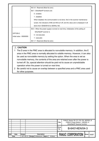
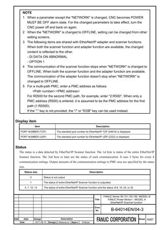
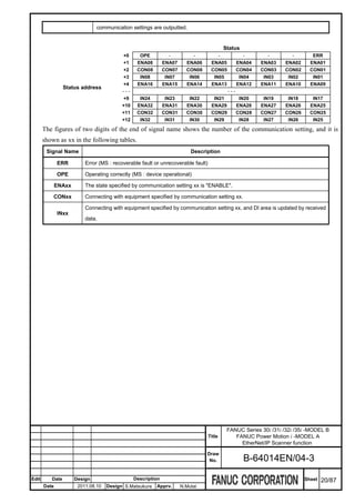
![List screen
2nd page is list screen. When the cursor is moved and the communication setting is selected, the outline of the
setting is displayed. The STATE can be changed to "ENABLE" or "DISABLE". And it is possible to move to a
simple screen.
EtherNet/IP Scanner setting screen (List)
Operation
Press soft key [(OPRT)] as needed and then use the following soft keys.
[(OPRT)] :
[STATE] :
Select a setting and press soft key [(OPRT)], [SIMPLE SET], then it is possible to move to a simple screen.
Setting item
Item Description
There are "ENABLE", "DISABLE", and "ERROR" state.
ENABLE : This setting is enabled. CNC is communicating by the preserved setting.
STATE This setting cannot be changed.
Initial value : "DISABLE" DISABLE, ERROR : This setting is disabled and the communication is not executed.
This setting can be changed.
In this screen, STATE can be changed to "ENABLE" or "DISABLE". When the item STATE
is changed to "ENABLE", the setting is confirmed. If there is not a problem, item STATE
FANUC Series 30i /31i /32i /35i -MODEL B
Title FANUC Power Motion i -MODEL A
EtherNet/IP Scanner function
Draw
No. B-64014EN/04-3
Edit Date Design Description Sheet 21/87
Date 2011.08.10 Design S.Matsukura Apprv. N.Mutai](https://image.slidesharecdn.com/b-64014en04-121129012902-phpapp02/85/B-64014-en-04-378-320.jpg)
![keeps "ENABLE". If there is a problem, item STATE change to "ERROR".
Soft key is used for setting. Press soft key [(OPRT)], [STATE], and then select [ENABLE]
or [DISABLE].
Display item
Item Description
Displays the state of each communication setting. This value corresponds to the "STATE"
in setting item.
LIST O : Enable
- : Disable
E : Error
SETTING NO. Number of the communication setting specified with the cursor.
IP ADDRESS IP address of the communication setting specified with the cursor.
Address, size, and RPI of the communication setting specified with the cursor.
ADDRESS, SIZE, RPI
Each of DI (T=>O) and DO (O=>T) value is displayed.
Data length per second, which communicates with an adapter of the communication setting
specified with the cursor.
DI+DO DATA_LEN/SEC
Both DI and DO length are counted. Setting unit is [byte / second]. If STATE is not
"ENABLE", this value is 0.
DI+DO DATA_LEN/SEC Total values of "DI+DO DATA_LEN/SEC" of all communication settings.
(TOTAL) Setting unit is [byte / second].
G.2.3.2 Simple screen
Procedure
1 On the list screen, move the cursor to select the communication setting.
2 Press soft key [(OPRT)], and then [SIMPLE]. The simple screen is displayed.
3 Press Page key to switch the page.
4 Input values to all setting items.
5 If necessary, move to detail screen to input values to detailed items.
6 To return to the list screen, press soft key [LIST].
FANUC Series 30i /31i /32i /35i -MODEL B
Title FANUC Power Motion i -MODEL A
EtherNet/IP Scanner function
Draw
No. B-64014EN/04-3
Edit Date Design Description Sheet 22/87
Date 2011.08.10 Design S.Matsukura Apprv. N.Mutai](https://image.slidesharecdn.com/b-64014en04-121129012902-phpapp02/85/B-64014-en-04-379-320.jpg)
![NOTE
If the "NETWORK" is ONLINE or the "STATE" is ENABLE, settings can be
displayed but setting cannot be changed. To change settings, change the
"NETWORK" to OFFLINE and change the "STATE" to DISABLE.
Simple screen
Settings to communicate with adapter equipment can be set.
1st page is a setting for the target that is the communication destination, and 2nd page is a setting for CNC that
is the originator.
EtherNet/IP Scanner setting screen (Simple 1/2, 2/2)
Operation
In the 2nd page, press soft key [DATA UNIT] or [ENDIAN CHANGE] as needed, then press the following soft
key.
[DATA UNIT] :
[ENDIAN CHANGE] :
To return to the list screen, press soft key [SET LIST].
To move to the detail screen, press soft key [DETAIL SET].
FANUC Series 30i /31i /32i /35i -MODEL B
Title FANUC Power Motion i -MODEL A
EtherNet/IP Scanner function
Draw
No. B-64014EN/04-3
Edit Date Design Description Sheet 23/87
Date 2011.08.10 Design S.Matsukura Apprv. N.Mutai](https://image.slidesharecdn.com/b-64014en04-121129012902-phpapp02/85/B-64014-en-04-380-320.jpg)
![Setting item
Item Description
Specify the IP address or the hostname of the adapter equipment of the communication
IP ADDRESS
destination.
Initial value : blank (SP)
To use a hostname, the DNS client function (No.904#5) is required.
ASSEMBLY INSTANCE
Specify the input assembly number, output assembly number, and configuration
Initial value : 0
assembly number of the adapter equipment assembly class.
Range of value:
When number is not used, set " " (blank).
0 to 65536
In "T=>O" or "O=>T", T means target (adapter) and O means originator (scanner)
or blank (SP)
SIZE
Initial value : 0 Specify the size (byte) of the area where input/output data is stored.
Range of value: 0 to 256
Specify the interval of sending data (packet) in EtherNet/IP.
RPI
T=>O means sending interval of Target (adapter).
Initial value : 32
O=>T means sending interval of Originator (scanner).
Range of value: 4 to 10000
Setting unit is 1ms.
Select the data unit from 1, 2, or 4 byte.
DATA UNIT
Soft key is used for setting. Press soft key [(OPRT)], [DATA UNIT], and then select from
Initial value : 1 byte
[1-BYTE], [2-BYTE], or [4-BYTE].
Specify whether to convert endian.
DISABLE : Endian is not converted.
ENDIAN
ENABLE : Endian is converted.
Initial value : DISABLE
Soft key is used for setting. Press soft key [(OPRT)], [ENDIAN CHANGE], and then
select from [ENABLE] or [DISABLE].
TYPE Specify the type of area where DI/DO data is stored.
Initial value : 0 00 : UNUSED DI/DO data is not stored. If input/output data size is 0, set this value.
Range of value: 0 or 1 01 : PMC DI/DO data is stored to PMC area.
Specify the address of the area where DI/DO data is stored.
When the item TYPE is "00:UNUSED ", the value cannot be set.
ADDRESS When the item TYPE is "01:PMC ", the start address of PMC area, R/D/E, can be set.
Initial value : --- The setting range depends on the actual range of R area, E area, and D area of PMC. It
is necessary to set the area specified by ADDRESS and SIZE within the range of PMC
area.
FANUC Series 30i /31i /32i /35i -MODEL B
Title FANUC Power Motion i -MODEL A
EtherNet/IP Scanner function
Draw
No. B-64014EN/04-3
Edit Date Design Description Sheet 24/87
Date 2011.08.10 Design S.Matsukura Apprv. N.Mutai](https://image.slidesharecdn.com/b-64014en04-121129012902-phpapp02/85/B-64014-en-04-381-320.jpg)
![CAUTION
1 The D area in the PMC area is allocated to nonvolatile memory. In addition, the E
area in the PMC area is normally allocated to volatile memory. However, it can also
be used as nonvolatile memory by setting the option. When the area is set as
nonvolatile memory, the contents of the area are retained even after the power is
turned off. So, special attention should be paid not to cause an unpredictable
operation when the power is turned on next time.
2 Be careful not to cause an overlap between a specified area and a PMC area used
for other purposes.
NOTE
For a multi-path PMC, enter a PMC address as follows:
<Path number>:<PMC address>
For R0500 for the second PMC path, for example, enter "2:R500". When only a
PMC address (R500) is entered, it is assumed to be the PMC address for the first
path (1:R0500).
If the ":" key is not provided, the "/" or "EOB" key can be used instead.
G.2.3.3 Detail screen
Procedure
1 On the simple screen, press soft key [DETAIL]. The detail screen is displayed.
2 Press Page key to switch the page.
3 Input values to setting items.
4 To return to the list screen, press soft key [LIST].
NOTE
If the "NETWORK" is ONLINE or the "STATE" is ENABLE, settings can be
displayed but setting cannot be changed. To change settings, change the
"NETWORK" to OFFLINE and change the "STATE" to DISABLE.
Detail screen
Detail settings to communicate with adapter equipment can be set.
1st page is a setting of data transfer for Target to Originator, and 2nd page is a setting of data transfer for
Originator to Target.
FANUC Series 30i /31i /32i /35i -MODEL B
Title FANUC Power Motion i -MODEL A
EtherNet/IP Scanner function
Draw
No. B-64014EN/04-3
Edit Date Design Description Sheet 25/87
Date 2011.08.10 Design S.Matsukura Apprv. N.Mutai](https://image.slidesharecdn.com/b-64014en04-121129012902-phpapp02/85/B-64014-en-04-382-320.jpg)
![EtherNet/IP Scanner setting screen (Detail 1/4, 2/4)
Operation
Press soft key [TRANSPORT], [HEADER FORMAT], or [PRIORITY] as needed, then press the following soft
key.
[TRANSPORT] :
[HEADER FORMAT] :
[PRIORITY] :
FANUC Series 30i /31i /32i /35i -MODEL B
Title FANUC Power Motion i -MODEL A
EtherNet/IP Scanner function
Draw
No. B-64014EN/04-3
Edit Date Design Description Sheet 26/87
Date 2011.08.10 Design S.Matsukura Apprv. N.Mutai](https://image.slidesharecdn.com/b-64014en04-121129012902-phpapp02/85/B-64014-en-04-383-320.jpg)
![3rd page is a setting of electronic key, and 4th page is a setting of whole communication.
EtherNet/IP Scanner setting screen (Detail 3/4, 3/4)
Operation
Press soft key [COMPATIBILITY], [TIME OUT], or [PRODUCT TRIGER] as needed, then press the
following soft key.
[COMPATIBILITY] :
[TIME OUT] :
[PRODUCT TRIGER] :
To return to the simple screen, press soft key [SIMPLE SET].
FANUC Series 30i /31i /32i /35i -MODEL B
Title FANUC Power Motion i -MODEL A
EtherNet/IP Scanner function
Draw
No. B-64014EN/04-3
Edit Date Design Description Sheet 27/87
Date 2011.08.10 Design S.Matsukura Apprv. N.Mutai](https://image.slidesharecdn.com/b-64014en04-121129012902-phpapp02/85/B-64014-en-04-384-320.jpg)
![Setting item
Item Description
Specify the data transport type between Target (adapter) and Originator (scanner), "1 to
multiple" or "1 to 1".
MULTICAST : 1 to multiple
TRANSPORT TYPE
UNICAST : 1 to 1 ("Point-to-Point")
Initial value : UNICAST
Only the T=>O transport type can be specified. The O=>T transport type is fixed as
"UNICAST".
Soft key is used for setting. Press soft key [TRANSPORT TYPE], and then select from
[MULTICAST] or [UNICAST].
Specify the header format used by data transport.
RUN/IDLE : Use 32 bit Run/Idle flag
MODELESS : Don't use Run/Idle flag, and header size is more than 1.
HEARTBEAT : Don't use Run/Idle flag, and header size is 0.
If header format for "O=>T" has not been changed from initial value, this is changed
automatically by the SIZE value. It is changed to "RUN/IDLE" if SIZE value is 1 or more,
and is changed to "HEARTBEAT" if SIZE value is 0.
When the value is specified from the screen, the specified value is used after that.
HEADER FORMAT
Soft key is used for setting. Press soft key [HEADER FORMAT], and then select from
Initial value :
[RUN/IDLE], [MODELESS], or [HEARTBEAT].
T => O : MODELESS
O => T : HEARTBEAT
This setting is specified according to the adapter equipment, and the following
combinations are frequently used
Exclusive Owner
T => O: MODELESS
O => T: RUN/IDLE
Input Only or Listen Only
T => O: MODELESS
O => T: HEARTBEAT
Specify the priority of the data transmission of EtherNet/IP.
LOW: Data is transmitted by low priority.
HIGH: Data is transmitted by high priority.
PRIORITY SCHEDULED: Data is transmitted regularly according to the specified RPI value.
Initial value: SCHEDULED URGENT: Data is transmitted by urgent priority.
Only the T=>O priority of the data transmission can be specified. The O=>T priority is
fixed as "SCHEDULED".
Soft key is used for setting. Press soft key [PRIORITY], and then select from [LOW],
FANUC Series 30i /31i /32i /35i -MODEL B
Title FANUC Power Motion i -MODEL A
EtherNet/IP Scanner function
Draw
No. B-64014EN/04-3
Edit Date Design Description Sheet 28/87
Date 2011.08.10 Design S.Matsukura Apprv. N.Mutai](https://image.slidesharecdn.com/b-64014en04-121129012902-phpapp02/85/B-64014-en-04-385-320.jpg)
![[HIGH], [SCHEDULE], or [URGENT].
If it is necessary to specify the adapter equipment to avoid communicating with the
adapter equipment not intended, input values to the following items from "VENDOR ID" to
"COMPATIBILITY".
ELECTRONIC KEY If it is not necessary to specify the adapter equipment, keep them to initialized value.
The adapter equipment verifies the ELECTRONIC KEY that received from scanner
equipment in the connection request and the own adapter information. If there is
difference, the connection request is refused.
VENDOR ID
Initial value : 0000H Specify the vendor ID of adapter equipment.
Range of value: Specify "0" if verification is not necessary.
0000H to FFFFH
DEVICE TYPE
Initial value : 0000H Specify the device type of adapter equipment.
Range of value: Specify "0" if verification is not necessary.
0000H to FFFFH
PRODUCT CODE
Initial value : 0000H Specify the product code of adapter equipment.
Range of value: Specify "0" if verification is not necessary.
0000H to FFFFH
REVISION Specify the revision of adapter equipment.
Initial value : 0.000 Format is the following.
Range of value : <Major number>.<Minor number>
0.0 to 127.255 Specify "0.0" if verification is not necessary.
Specify the presence of the compatibility of the specified Electronic key information
verification.
DISABLE (All of electronic key item has not been changed from initial value.):
Electronic key information is not sent to the adapter equipment. Therefore, it is
not verified.
DISABLE (Some of electronic key item had been changed.):
COMPATIBILITY
Electronic key information is sent to the adapter equipment, and is verified
Initial value : DISABLE
without compatibility. It is possible to connect only when the value of all items
agree with the adapter equipment.
ENABLE:
Electronic key information is sent to the adapter equipment, and is verified with
compatibility. It is possible to connect if the adapter equipment judges it is
compatible even if information of the electronic key is different.
FANUC Series 30i /31i /32i /35i -MODEL B
Title FANUC Power Motion i -MODEL A
EtherNet/IP Scanner function
Draw
No. B-64014EN/04-3
Edit Date Design Description Sheet 29/87
Date 2011.08.10 Design S.Matsukura Apprv. N.Mutai](https://image.slidesharecdn.com/b-64014en04-121129012902-phpapp02/85/B-64014-en-04-386-320.jpg)
![It is necessary to set a correct value to "VENDOR ID", "PRODUCT CODE", and
Major number of "REVISION".
Soft key is used for setting. Press soft key [COMPATIBILITY], and then select from
[ENABLE] or [DISABLE].
Specify the multiplier used to calculate of the timeout value for the sending/receiving of
TIMEOUT MULTIPLIER the DI/DO data.
Initial value : x4 Timeout value = RPI value of DI (T=>O) * TIMEOUT MULTIPLIER
Range of value : When the timeout multiplier is [x4] and RPI is 10ms, if 40 ms pass from the last data
x4 to x512 reception and the following data is not received yet, it is judged to be a timeout.
Soft key is used for setting. Press soft key [TIMEOUT], and then select from [x4] to [x512].
Specify the time until reconnection is demanded when the connection is closed by some
reasons. Setting unit is 1 second.
RECONNECT It is reconnected after waiting the time specified again when failing in reconnection.
Initial value : 0 ---:
Range of value : Reconnection is disabled. To specify this input " " (blank).
0 to 60, blank 0 to 60:
Demand reconnection when the specified time passes.
Initial value 0 means 10 seconds.
Specify the timing that the adapter equipment transmits data.
CYCLIC:
Data is transmitted regularly according to the specified RPI value.
CHANGE STATE:
Data is transmitted regularly according to the specified RPI value.
In addition, adapter equipment transmits data when state of the equipment
PRODUCTION TRIGGER changes.
Initial value: CYCLIC APPLICATION:
Data is transmitted regularly according to the specified RPI value.
In addition, adapter equipment can transmit data according to the arbitrary
timing.
The timing that the scanner equipment transmits data is fixed as "CYCLIC".
Soft key is used for setting. Press soft key [PRODUCT TRIGGER], and then select from
[CYCLIC], [CHANGE STATE], and [APPLICATION].
OPTION1 Bit 0-7:
Initial value: 00000000 Reserved (Must be zero)
OPTION2 Bit 0-7:
Initial value: 00000000 Reserved (Must be zero)
FANUC Series 30i /31i /32i /35i -MODEL B
Title FANUC Power Motion i -MODEL A
EtherNet/IP Scanner function
Draw
No. B-64014EN/04-3
Edit Date Design Description Sheet 30/87
Date 2011.08.10 Design S.Matsukura Apprv. N.Mutai](https://image.slidesharecdn.com/b-64014en04-121129012902-phpapp02/85/B-64014-en-04-387-320.jpg)
![G.2.4 BACKING UP AND RESTORING SETTING
This section explains how to back up or restore the setting of EtherNet/IP Scanner function.
The setting can be preserved in the memory card or USB memory.
When backing up and restoring the setting of EtherNet/IP Scanner function, the communication parameters of
the Ethernet function is backed up and restored too.
Procedure
1 Press function key .
2 Soft key [ETHERNET] appears. (When soft key does not appear, press the continue key.)
3 Press soft key [ETHERNET] to display Ethernet Setting screen.
4 Press soft key [EIP S SET] to display EtherNet/IP Scanner screen. (When soft key does not appear, press
the continue key.)
5 Press soft key [(OPRT)], and then [+]. The soft keys [BACKUP], [RESTORE], [ALL BACKUP], and
[ALL RESTORE] for backing up or restoring settings appear.
6 Press the soft key [BACKUP], [RESTORE], [ALL BACKUP], or [ALL RESTORE]. The soft keys
[EXECUTE] and [CANCEL] appear.
7 Enter the name of a file to be backed up or restored in the key-in buffer, and press the soft key
[EXECUTE]. The operation selected at the above step is executed.
The character string "EXECUTING" blinks during execution.
FANUC Series 30i /31i /32i /35i -MODEL B
Title FANUC Power Motion i -MODEL A
EtherNet/IP Scanner function
Draw
No. B-64014EN/04-3
Edit Date Design Description Sheet 31/87
Date 2011.08.10 Design S.Matsukura Apprv. N.Mutai](https://image.slidesharecdn.com/b-64014en04-121129012902-phpapp02/85/B-64014-en-04-388-320.jpg)
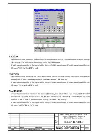
![ALL RESTORE
All valid communication parameters for embedded Ethernet, Fast Ethernet/Fast Data Server, PROFIBUS-DP
master/slave, DeviceNet master/slave, FL-net, CC-Link remote device and EtherNet/IP Scanner/Adapter are
read from the memory card or the USB memory and saved to the SRAM of the CNC main unit.
However, if a communication function related to a valid communication parameter is disabled in the CNC, that
parameter is not saved to the SRAM.
If a file name is specified in the key-in buffer, the specified file name is used. If no file name is specified, the
file name "NETWORK.MEM" is used.
CAUTION
While an external input/output device such as the memory card or USB memory is
being accessed, do not turn the power to the CNC off or remove the external
input/output device. Doing so may damage the external input/output device.
NOTE
1 A backup or restore operation for communication parameters can only be
performed in the MDI mode, EDIT mode, or emergency stop state.
2 When communication parameters are restored, an alarm condition occurs that
requires power-off.
3 When the output level of 8-level data protection of Ethernet function is higher than
that of the operation level, all backup/backup cannot be done, and warning
message "PROTECTED" is displayed. (When other communication features exist,
all backup is possible. )
4 When the change level of 8-level data protection of Ethernet function is higher than
the operation level, restore/all restore cannot be done, and warning message
"PROTECTED" is displayed. (When other communication features exist, all restore
is possible. )
Related NC parameter
0020 I/O CHANNEL: Input/output device selection, or interface number for a foreground
0020
input/output device
[Input type] Setting input
[Data type] Byte
[Valid data range] 4: Selects the memory card as the input/output device.
17: Selects the USB memory as the input/output device.
It is not possible to backup and restore the communication parameters by using other devices.
FANUC Series 30i /31i /32i /35i -MODEL B
Title FANUC Power Motion i -MODEL A
EtherNet/IP Scanner function
Draw
No. B-64014EN/04-3
Edit Date Design Description Sheet 33/87
Date 2011.08.10 Design S.Matsukura Apprv. N.Mutai](https://image.slidesharecdn.com/b-64014en04-121129012902-phpapp02/85/B-64014-en-04-390-320.jpg)
![G.2.5 OUTPUT OF EDS FILE
This chapter explains the method of outputting the EDS file to the memory card or the USB memory.
When both the scanner function and the adapter function are available, the contents of output to the EDS file can
be specified by the OPTION 1 Bit 2 in the basic screen.
OPTION 1 Bit 2 value
The contents of output to the EDS file
in the basic screen
Output the EDS file for the scanner function when outputting it from the scanner function
setting screen. Output the EDS file for the adapter function when outputting it from the
0 adapter function setting screen.
Standard EDS file name for the scanner function is "FSCNC101.EDS", and standard file
name for the adapter function is "F_CNC101.EDS".
Output the EDS file which include the contents for both the adapter and the scanner
1
function regardless of the output screen. Standard EDS file name is "FWCNC101.EDS".
Procedure
1 Press function key .
2 Soft key [ETHERNET] appears. (When soft key does not appear, press the continue key.)
3 Press soft key [ETHERNET] to display Ethernet Setting screen.
4 Press soft key [EIP S SET] to display EtherNet/IP Scanner screen. (When soft key does not appear, press
the continue key.)
5 Press soft key [(OPRT)], and then [+]. The soft key [EDS OUTPUT] appears.
6 Press the soft key [EDS OUTPUT]. The soft keys [EXECUTE] and [CANCEL] appear.
7 Enter the file name of EDS file in the key-in buffer, and press the soft key [EXECUTE] to output EDS file.
If the file name is not specified, the standard file name is used.
The character string "EXECUTING" blinks during execution.
FANUC Series 30i /31i /32i /35i -MODEL B
Title FANUC Power Motion i -MODEL A
EtherNet/IP Scanner function
Draw
No. B-64014EN/04-3
Edit Date Design Description Sheet 34/87
Date 2011.08.10 Design S.Matsukura Apprv. N.Mutai](https://image.slidesharecdn.com/b-64014en04-121129012902-phpapp02/85/B-64014-en-04-391-320.jpg)
![CAUTION
While an external input/output device such as the memory card or USB memory is
being accessed, do not turn the power to the CNC off or remove the external
input/output device. Doing so may damage the external input/output device.
NOTE
1 Output of EDS file can only be performed in the MDI mode or EDIT mode.
2 When the 8-level data protection function is enabled, whether output of EDS file is
allowed or not depends on the setting of that function.
Related NC parameter
0020 I/O CHANNEL: Input/output device selection, or interface number for a foreground
0020
input/output device
[Input type] Setting input
[Data type] Byte
[Valid data range] 4: Selects the memory card as the input/output device.
17: Selects the USB memory as the input/output device.
It is not possible to backup and restore the communication parameters by using other devices.
FANUC Series 30i /31i /32i /35i -MODEL B
Title FANUC Power Motion i -MODEL A
EtherNet/IP Scanner function
Draw
No. B-64014EN/04-3
Edit Date Design Description Sheet 35/87
Date 2011.08.10 Design S.Matsukura Apprv. N.Mutai](https://image.slidesharecdn.com/b-64014en04-121129012902-phpapp02/85/B-64014-en-04-392-320.jpg)
![G.2.6 Initialize
In the list screen, the communication setting specified with the cursor can be initialized
Procedure
1 Press function key .
2 Soft key [ETHERNET] appears. (When soft key does not appear, press the continue key.)
3 Press soft key [ETHERNET] to display Ethernet Setting screen.
4 Press soft key [EIP S SET]. (When soft key does not appear, press the continue key.)
5 Press page key to display 2nd page, list screen.
6 Press soft key [(OPRT)], press soft key [+] twice, then the soft key [INITIALIZE] for initialize appears.
7 Move the cursor to select the communication setting to be initialized.
8 Press soft key [INITIALIZE], soft key [EXECUTE] and [CANCEL] are displayed.
9 Press soft key [EXECUTE] then selected communication setting is initialized.
FANUC Series 30i /31i /32i /35i -MODEL B
Title FANUC Power Motion i -MODEL A
EtherNet/IP Scanner function
Draw
No. B-64014EN/04-3
Edit Date Design Description Sheet 36/87
Date 2011.08.10 Design S.Matsukura Apprv. N.Mutai](https://image.slidesharecdn.com/b-64014en04-121129012902-phpapp02/85/B-64014-en-04-393-320.jpg)
![G.2.7 EtherNet/IP SCANNER MAINTENANCE SCREEN
This section explains maintenance screens for EtherNet/IP Scanner function. Maintenance screens consist of the
following screens.
Scanner information 1/3
Maintenance information list 2/3 Detail information
Adapter information acquisition 3/3
Consist of maintenance screens of EtherNet/IP Scanner function
In the scanner information screen, the scanner information can be confirmed.
The maintenance list screen shows information list of connected adapter, and it is possible to move to detail
information screen from this screen.
The adapter information acquisition screen can acquire the adapter information specified by IP address and can
show them.
G.2.7.1 Scanner information screen, Maintenance information list screen,
Adapter information acquisition screen
Procedure
1 Press function key .
2 Soft key [ETHERNET] appears. (When soft key does not appear, press the continue key.)
3 Press soft key [ETHERNET] to display Ethernet Setting screen.
4 Press soft key [EIP S MAINTE]. (When soft key does not appear, press the continue key.)
5 The scanner information screen on the 1st page is displayed. Press Page key to switch the
page.
FANUC Series 30i /31i /32i /35i -MODEL B
Title FANUC Power Motion i -MODEL A
EtherNet/IP Scanner function
Draw
No. B-64014EN/04-3
Edit Date Design Description Sheet 37/87
Date 2011.08.10 Design S.Matsukura Apprv. N.Mutai](https://image.slidesharecdn.com/b-64014en04-121129012902-phpapp02/85/B-64014-en-04-394-320.jpg)
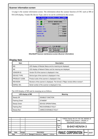
![The LED display of NS and its meaning is as follows.
LED display of NS Meaning
Steady Off (MS is steady off too) ---
Steady Off NO IP ADDRESS
Flashing Green NO CONNECTIONS
Steady Green CONNECTED
Flashing Red CONNECTION TIMEOUT
Steady Red DUPLICATE IP ADDRESS
Maintenance information list screen
Page 2 is a maintenance information list screen. Each communication setting state is displayed.
EtherNet/IP Scanner maintenance screen (Maintenance information list)
Operation
When the cursor is moved and the communication setting is selected, the outline of the setting is displayed.
Press soft key [DETAIL], it is possible to move to the detail information screen about selected communication
setting.
Press soft key [GET INFO], it is possible to move to the adapter information acquisition screen and can acquire
the adapter information.
FANUC Series 30i /31i /32i /35i -MODEL B
Title FANUC Power Motion i -MODEL A
EtherNet/IP Scanner function
Draw
No. B-64014EN/04-3
Edit Date Design Description Sheet 39/87
Date 2011.08.10 Design S.Matsukura Apprv. N.Mutai](https://image.slidesharecdn.com/b-64014en04-121129012902-phpapp02/85/B-64014-en-04-396-320.jpg)
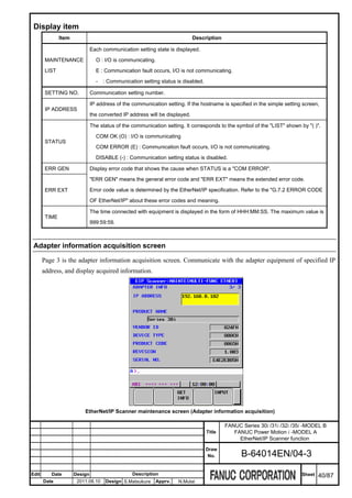
![Operation
1 Specify a value to "IP ADDRESS" and press [GET INFO].
2 This screen communicates with the adapter equipment of specified IP address, and display acquired
information.
NOTE
Depending on circumstances of some adapter equipment, the transmission of the
I/O data might stop when information acquisition is executed from this screen while
transmitting the I/O data.
Use information acquisition of this screen only for confirming communication target
in case of network setting.
Do not use information acquisition of this screen when system operation is actually
begun, and when the I/O data is transmitted.
Setting item
Item Description
IP ADDRESS Specify the IP address or host name of the adapter equipment to acquire information.
Display item
Item Description
PRODUCT NAME Acquired product name is displayed. "GET INFO ERROR" is displayed when acquisition fails.
VENDOR ID Acquired vendor ID is displayed.
DEVICE TYPE Acquired device type is displayed.
PRODUCT CODE Acquired product code is displayed.
REVISION Acquired revision is displayed.
SERIAL NO. Acquired serial number is displayed.
G.2.7.2 Detail information screen
Procedure
1 On the maintenance list screen, move the cursor to select the communication setting.
2 Press soft key [DETAIL], detail information screen is displayed.
FANUC Series 30i /31i /32i /35i -MODEL B
Title FANUC Power Motion i -MODEL A
EtherNet/IP Scanner function
Draw
No. B-64014EN/04-3
Edit Date Design Description Sheet 41/87
Date 2011.08.10 Design S.Matsukura Apprv. N.Mutai](https://image.slidesharecdn.com/b-64014en04-121129012902-phpapp02/85/B-64014-en-04-398-320.jpg)
![EtherNet/IP Scanner maintenance screen (Detail information)
Operation
Press soft key [LIST] to return to the maintenance list screen.
Press soft key [GET INFO], it is possible to move to the adapter information acquisition screen and can acquire
the adapter information.
Display item
Item Description
IP ADDRESS IP address of the selected communication setting is displayed.
STATUS
ERR GEN
These are same as items in the maintenance information list screen.
ERR EXT
TIME
RPI (ms) The value of RPI set in the simple screen is displayed. Setting unit is 1ms.
It is a sending and receiving interval of the DI/DO data that EtherNet/IP Scanner function actually
API (ms) processed.
O=>T means DO data receive interval, and T=>O means DI data send interval. Setting unit is 1ms.
It is a number of packets that the Scanner function normally received.
RECV
The range is from 0 to 65535. The value returns to 0 when it exceeds 65535.
It is a number of packets that were not able to receive by the Scanner function.
LOST
The range is from 0 to 65535. The value returns to 0 when it exceeds 65535.
SEND It is a number of packets that the Scanner function normally sent.
FANUC Series 30i /31i /32i /35i -MODEL B
Title FANUC Power Motion i -MODEL A
EtherNet/IP Scanner function
Draw
No. B-64014EN/04-3
Edit Date Design Description Sheet 42/87
Date 2011.08.10 Design S.Matsukura Apprv. N.Mutai](https://image.slidesharecdn.com/b-64014en04-121129012902-phpapp02/85/B-64014-en-04-399-320.jpg)
![The range is from 0 to 65535. The value returns to 0 when it exceeds 65535.
G.2.8 EtherNet/IP FUNCTIONS LOG SCREEN
The log screen shows the log data about EtherNet/IP Adapter and Scanner function.
Procedure
1 Press function key .
2 Press soft key [ETHER LOG] to display the Ethernet log screen. (When soft key does not appear, press the
continue key.)
3 Press soft key [ETHERNET/IP], and then the information related to EtherNet/IP functions is displayed.
EtherNet/IP functions log screen
The latest log information is displayed at the top of the screen. At the right end of a log item, the occurrence
date and time of the log item is indicated. Date and time data is indicated in the format "MMM.DD hh:mm:ss",
where MMM represents a month, DD represents a day, hh represents hour, mm represents minute, and ss
represents second.
To clear the log information, press soft key [(OPRT)] then soft key [CLEAR].
FANUC Series 30i /31i /32i /35i -MODEL B
Title FANUC Power Motion i -MODEL A
EtherNet/IP Scanner function
Draw
No. B-64014EN/04-3
Edit Date Design Description Sheet 43/87
Date 2011.08.10 Design S.Matsukura Apprv. N.Mutai](https://image.slidesharecdn.com/b-64014en04-121129012902-phpapp02/85/B-64014-en-04-400-320.jpg)
![NOTE
The log information of EtherNet/IP functions is stored in volatile memory and it is
lost when the power of CNC is turned off. Check the log information when an error
occurs.
The following lists major log message:
In the "A/S", "A" means log of the Adapter function, and "S" means log of the Scanner function.
XX means a general error code, and YY means an extended error code. Refer to the "G.7.2 ERROR CODE OF
EtherNet/IP" for the detail of these error codes.
Error Code Log message A/S Meaning and action to be taken
E-1107 EtherNet/IP function and FL-net function A It is specified that the EtherNet/IP function and the
cannot be used at the same time S FL-net function are operated with the same
hardware. Please confirm the value of parameter
No.970, 971, and 972.
E-1109 All Connections of EtherNet/IP Adapter are A The connection request sent from the scanner was
busy [General=XXH:Extended=YYH] refused because the connection number exceed
maximum number(32).
All Connections of EtherNet/IP Adapter are S The scanner sent connection request to the
busy adapter, but it was refused because all connection
[General=XXH:Extended=YYH:Scanner] of the adapter had already been used.
E-110A Connect Request from EtherNet/IP Scanner A The unacceptable connection request was received
is refused from the scanner.
E-110B Connect Request from EtherNet/IP Scanner A The unacceptable connection request was received
is refused (RPI Error) from the scanner.
RPI specified from the scanner is beyond the limits
of value (4-10,000ms) that can be accepted.
E-110C Connect Request from EtherNet/IP Scanner A The unacceptable connection request was received
is refused (DI/DO Size Error) from the scanner.
The size of DI or DO specified from the scanner is
different from the size specified by the allocation
setting.
FANUC Series 30i /31i /32i /35i -MODEL B
Title FANUC Power Motion i -MODEL A
EtherNet/IP Scanner function
Draw
No. B-64014EN/04-3
Edit Date Design Description Sheet 44/87
Date 2011.08.10 Design S.Matsukura Apprv. N.Mutai](https://image.slidesharecdn.com/b-64014en04-121129012902-phpapp02/85/B-64014-en-04-401-320.jpg)
![Error Code Log message A/S Meaning and action to be taken
E-110D Connect Request from EtherNet/IP Scanner A The unacceptable connection request was received
is refused (Assembly Instance Error) from the scanner.
The instance of the Assembly object specified from
the scanner is not in the adapter function. The
instance of the Assembly object is created if the
allocation setting is enabled. Please confirm
whether the allocation setting is enabled.
E-110E [Connection has timed out. (Adapter:UU)] A The allocation setting number UU has timed out.
[Connection has timed out. (Scanner:VV)] S The communication setting number VV has timed
out.
E-110F [Connection has closed. (Adapter:UU)] A The allocation setting number UU has closed.
[Connection has closed. (Scanner:VV)] S The communication setting number VV has closed.
E-1151 Response from EtherNet/IP Adapter was not S The connection request was sent to the adapter, but
received [General=XXH:Extended=YYH] the response from the adapter was not received.
Confirm whether the adapter power supply is on, or
whether the adapter is correctly connected to the
network.
E-1152 Error Response from EtherNet/IP Adapter S The error response was received from the adapter.
was received [General=XXH:Extended=YYH]
E-1153 Connect Request is refused S The connection request from the scanner was
[General=XXH:Extended=YYH] refused by the adapter.
E-1154 Connect Request is refused (DI/DO Size S The connection request from the scanner was
Error) [General=XXH:Extended=YYH] refused by the adapter. The size of DI/DO specified
by the scanner is different from the adapter.
E-1155 Connect Request is refused (RPI Error) S The connection request from the scanner was
[General=XXH:Extended=YYH] refused by the adapter. RPI specified by the
scanner cannot be accepted with the adapter.
E-1156 Connect Request is refused (ElectronicKey S The connection request from the scanner was
Mismatch) [General=XXH:Extended=YYH] refused by the adapter. The electronic key specified
by the scanner is different from the adapter.
E-1157 Connect Request is refused (Assembly S The connection request from the scanner was
Instance Error) refused by the adapter. The assembly instance
[General=XXH:Extended=YYH] specified by the scanner cannot be used in the
adapter.
FANUC Series 30i /31i /32i /35i -MODEL B
Title FANUC Power Motion i -MODEL A
EtherNet/IP Scanner function
Draw
No. B-64014EN/04-3
Edit Date Design Description Sheet 45/87
Date 2011.08.10 Design S.Matsukura Apprv. N.Mutai](https://image.slidesharecdn.com/b-64014en04-121129012902-phpapp02/85/B-64014-en-04-402-320.jpg)
![G.3 RELATING NC PARAMETER
NC parameter related to EtherNet/IP functions is as follows.
#7 #6 #5 #4 #3 #2 #1 #0
904 DHC DNS
NOTE
When this parameter is set, the power must be turned off before operation is
continued.
[Input type] Parameter input
[Data type] Bit
#5 DNS : The DNS client function is:
0: Not used.
1: Used.
#6 DHC : The DHCP client function is:
0: Not used.
1: Used.
#7 #6 #5 #4 #3 #2 #1 #0
907 100 FUL FIX
NOTE
When this parameter is set, the power must be turned off before operation is
continued.
[Input type] Parameter input
[Data type] Bit
#0 FIX : In a hardware where EtherNet/IP Adapter function or EtherNet/IP Scanner function
is running, the auto-negotiation of Ethernet communication is
0 : valid. (10Mbps/100Mbps and full duplex/half duplex is distinguished automatically.)
1 : invalid. (The setting is specified by the following parameters, #1 FUL and #2 100.)
#1 FUL : In a hardware where EtherNet/IP Adapter function or EtherNet/IP Scanner function
is running, the communication of Ethernet is
FANUC Series 30i /31i /32i /35i -MODEL B
Title FANUC Power Motion i -MODEL A
EtherNet/IP Scanner function
Draw
No. B-64014EN/04-3
Edit Date Design Description Sheet 46/87
Date 2011.08.10 Design S.Matsukura Apprv. N.Mutai](https://image.slidesharecdn.com/b-64014en04-121129012902-phpapp02/85/B-64014-en-04-403-320.jpg)
![0 : Half-duplex.
1 : Full-duplex
This bit is effective only if #0 FIX is 1.
#2 100 : In a hardware where EtherNet/IP Adapter function or EtherNet/IP Scanner function
is running, the transmission rate of Ethernet is
0 : 10Mbps
1 : 100Mbps
This bit is effective only if #0 FIX is 1.
0970 Select hardware that operates Ethernet or Data Server function
0971 Select hardware that operates first FL-net function
0972 Select hardware that operates second FL-net function
NOTE
When this parameter is set, the power must be turned off before operation is
continued.
[Input type] Parameter input
[Data type] Byte
[Valid data range] -1 to 6
Hardware that operates each function is selected.
Value Hardware
-1 Not used
0 Unsetting
1 Multi-function Ethernet
2 (reserved)
3 Fast Ethernet board mounted in slot 1
4 Fast Ethernet board mounted in slot 2
5 Fast Ethernet board mounted in slot 3
6 Fast Ethernet board mounted in slot 4
FANUC Series 30i /31i /32i /35i -MODEL B
Title FANUC Power Motion i -MODEL A
EtherNet/IP Scanner function
Draw
No. B-64014EN/04-3
Edit Date Design Description Sheet 47/87
Date 2011.08.10 Design S.Matsukura Apprv. N.Mutai](https://image.slidesharecdn.com/b-64014en04-121129012902-phpapp02/85/B-64014-en-04-404-320.jpg)
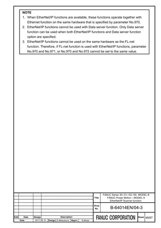
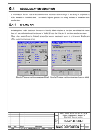
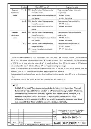
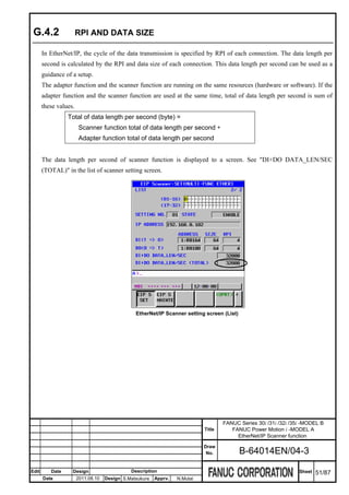
![The data length per second of adapter function can be calculated by RPI value specified by scanner.
The adapter function supports maximum four allocation settings. The total of data length per second is obtained
by totaling these values.
Total of data length of the adapter function per second (byte) =
1000
( Size of Allocation setting No.1 (DI + DO)) (byte) * )+
RPI of Allocation setting No.1 (ms)
1000
( Size of Allocation setting No.2 (DI + DO)) (byte) * )+
RPI of Allocation setting No.2 (ms)
1000
( Size of Allocation setting No.3 (DI + DO)) (byte) * )+
RPI of Allocation setting No.3 (ms)
1000
( Size of Allocation setting No.4 (DI + DO)) (byte) * )
RPI of Allocation setting No.4 (ms)
NOTE
Both DI size and DO size are added to the data length per second.
The maximum value of the total of data length per second that EtherNet/IP functions of CNC can operate is
about 128,000 bytes. Please adjust the setting of RPI and the data size within this range.
In addition, if CNC communicates with two or more equipments, set the larger value than the value of "Number
of connected equipment * 2 [ms]" to the RPI. If the number of connected equipment is five, set the larger value
than 10ms to RPI. The minimum value of RPI is 4ms.
NOTE
The above-mentioned maximum value of the total of data length per second is
guidance. This is not guarantee of the performance. When EtherNet/IP functions
are used together with other Ethernet functions like "FOCAS2/Ethernet function" or
"CNC screen display function", it is necessary to give a margin enough.
FANUC Series 30i /31i /32i /35i -MODEL B
Title FANUC Power Motion i -MODEL A
EtherNet/IP Scanner function
Draw
No. B-64014EN/04-3
Edit Date Design Description Sheet 52/87
Date 2011.08.10 Design S.Matsukura Apprv. N.Mutai](https://image.slidesharecdn.com/b-64014en04-121129012902-phpapp02/85/B-64014-en-04-409-320.jpg)
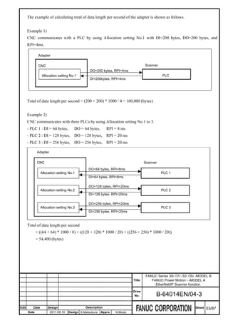
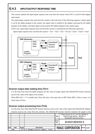
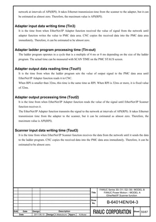
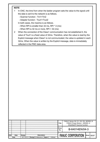
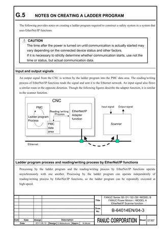
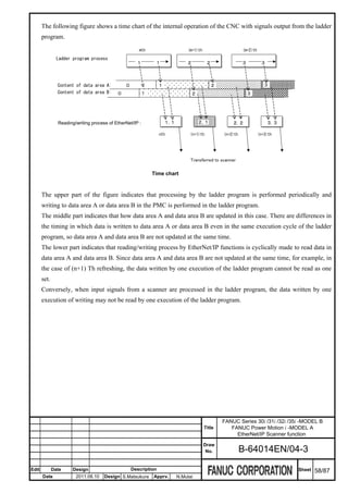
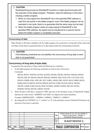
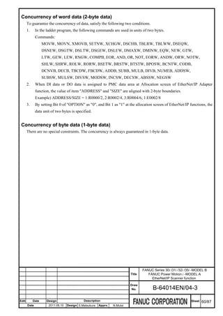
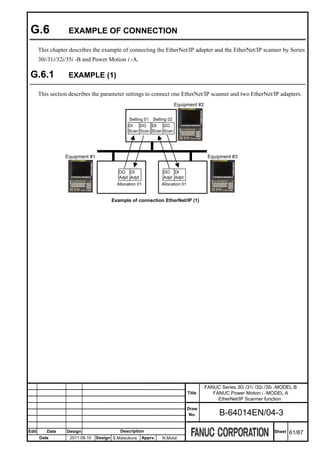
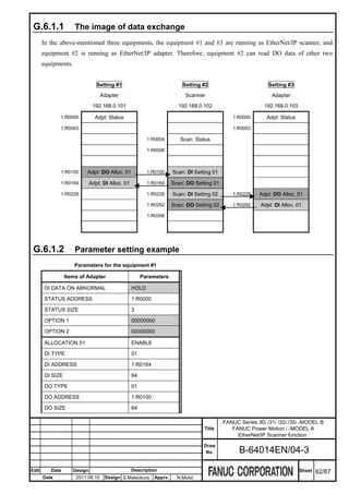
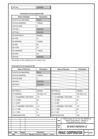
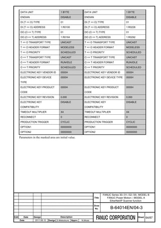
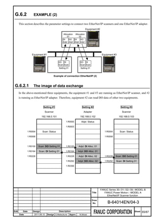
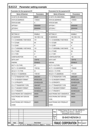
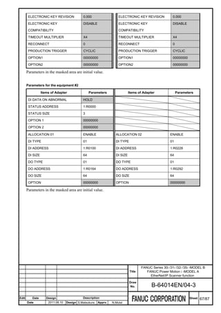
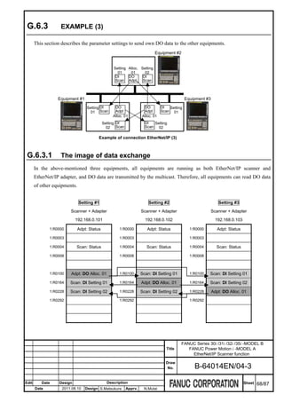
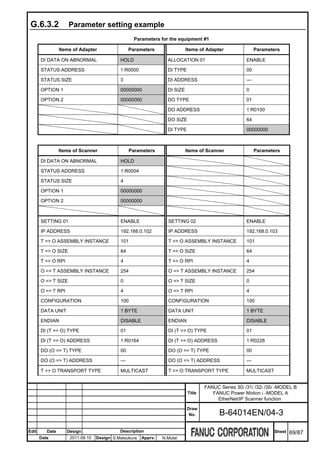
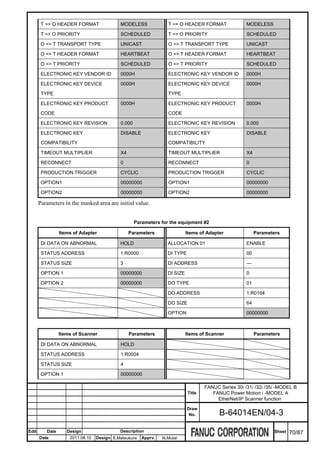
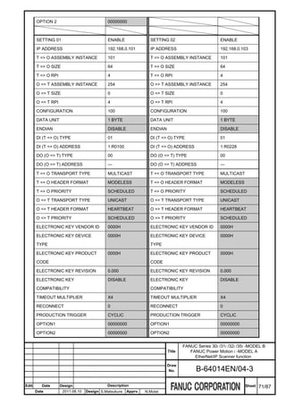
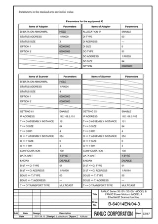
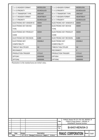
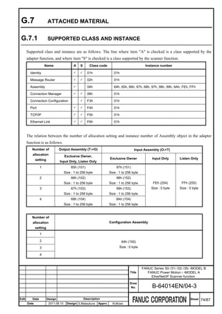
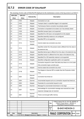
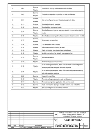
![G.7.3 SCANNER SETUP BY EDS FILE
This chapter describes the contents of the EDS file of the adapter, and the method of setting them to a setup
screen of the scanner.
G.7.3.1 Structure of the EDS file
The EDS file is classified in the section. It is possible to set two or more fields in the one section.
The parameter is set to each field. ";" (semicolon) is placed at the end of the parameter.
It is possible to set two or more parameters in the one field. In that case, the separator "," is placed between
parameter and parameter.
It is a comment from character "$" to the end of line.
$Comment
[Section name 1]
Field name 1= Parameter;
Field name 2= Parameter 1, Parameter 2, Parameter 3;
---
[Section name 2]
---
G.7.3.2 Section [Device]
The equipment information of the adapter is described in the section [Device]. Input this value to
"ELECTRONIC KEY" of the detail screen. However, if the confirmation of the adapter equipment is
unnecessary, there is no need to change the value of "ELECTRONIC KEY" from the initial value.
Setting item of the detail screen Field name in the EDS file
VENDOR ID VendCode
DEVICE TYPE ProdType
PRODUCT CODE ProdCode
REVISION MajRev
MinRev
FANUC Series 30i /31i /32i /35i -MODEL B
Title FANUC Power Motion i -MODEL A
EtherNet/IP Scanner function
Draw
No. B-64014EN/04-3
Edit Date Design Description Sheet 77/87
Date 2011.08.10 Design S.Matsukura Apprv. N.Mutai](https://image.slidesharecdn.com/b-64014en04-121129012902-phpapp02/85/B-64014-en-04-434-320.jpg)
![Example)
[Device]
VendCode = 591;
ProdType = 12;
ProdCode = 101;
MajRev = 1;
MinRev = 3;
The setting value of the "ELECTRONIC KEY" is as follows in case of the above-mentioned EDS file.
Setting item of the detail screen Parameter
VENDOR ID 591(Dec) / 24F (Hex)
DEVICE TYPE 12(Dec) /C (Hex)
PRODUCT CODE 101(Dec) /65 (Hex)
REVISION 1.3
G.7.3.3 Section [Connection Manager]
The specification of the connection that can be created by Adapter equipment is described in the section
[Connection Manager].
If more than one field is specified, select the suitable field by referring the 13th parameter, "Connection name".
15 parameters specified in the field and the correspondences of input item of the scanner setting screen are as
follows.
Setting item in the Parameter in the Description Remarks
setting screen EDS file
(None) 1st parameter Bit 0 : Class 0 This is the communication class.
Bit 0-6 Bit 1 : Class 1 The scanner function supports only
Bit 2 : Class 2 class 1.
Bit 3 : Class 3
Bit 4 : Class 4
Bit 5 : Class 5
Bit 6 : Class 6
PRODUCTION 1st parameter Bit 16 : CYCLIC
TRIGGER Bit 16-18 Bit 17 : CHANGE STATE
Bit 18 : APPLICATION
(None) 1st parameter Bit 24 : Listen Only This is the communication type
FANUC Series 30i /31i /32i /35i -MODEL B
Title FANUC Power Motion i -MODEL A
EtherNet/IP Scanner function
Draw
No. B-64014EN/04-3
Edit Date Design Description Sheet 78/87
Date 2011.08.10 Design S.Matsukura Apprv. N.Mutai](https://image.slidesharecdn.com/b-64014en04-121129012902-phpapp02/85/B-64014-en-04-435-320.jpg)
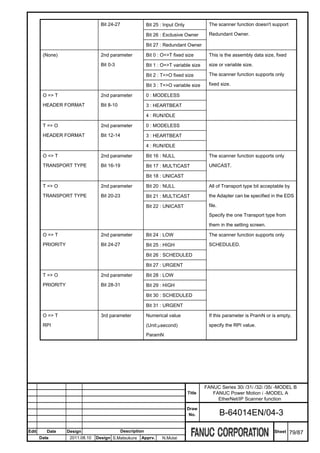
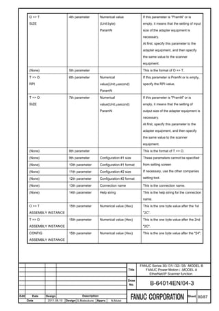
![Example)
[Connection Manager]
Connection1 =
0x04010002,
0x44640405,
Param1, Param2, ,
Param3, Param4, ,
,,
,,
"class1 - exclusive owner",
"",
"20 04 24 64 2C 97 2C 65";
The setting value of scanner setting screens to communicate with the above-mentioned EDS file is as follows.
Setting item Screen Parameter
Transport trigger Detail setting 4/4 CYCLIC
O => T Header format Detail setting 2/4 RUN/IDLE
T => O Header format Detail setting 1/4 MODELESS
O => T Transport type Detail setting 2/4 UNICAST
T => O Transport type Detail setting 1/4 UNICAST
(Select from UNICAST or MULTICAST)
O => T Priority Detail setting 2/4 SCHEDULED (Fixed)
T => O Priority Detail setting 1/4 SCHEDULED
O => T RPI Simple setting 1/2 Specify the needed communication interval.
O => T Size Simple setting 1/2 Specify size suitable for the adapter equipment.
T => O RPI Simple setting 1/2 Specify the needed communication interval.
T => O Size Simple setting 1/2 Specify size suitable for the adapter equipment.
O => T Assembly instance Simple setting 1/2 151 (Decimal)
T => O Assembly instance Simple setting 1/2 101 (Decimal)
Configuration Assembly instance Simple setting 1/2 100 (Decimal)
It is necessary to specify about CNC such as PMC address, etc. in the 2/2 page of the simple screen.
FANUC Series 30i /31i /32i /35i -MODEL B
Title FANUC Power Motion i -MODEL A
EtherNet/IP Scanner function
Draw
No. B-64014EN/04-3
Edit Date Design Description Sheet 81/87
Date 2011.08.10 Design S.Matsukura Apprv. N.Mutai](https://image.slidesharecdn.com/b-64014en04-121129012902-phpapp02/85/B-64014-en-04-438-320.jpg)
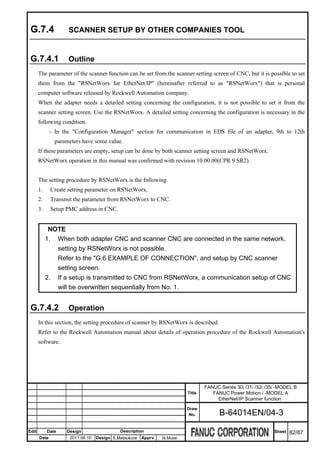
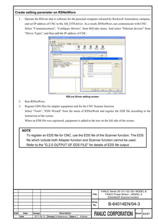
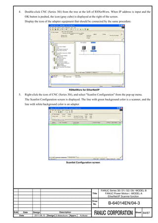
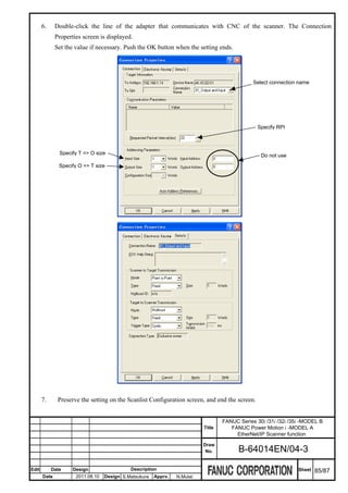
![Transmit the parameter from RSNetWorx to CNC
8. Change the "NETWORK" from ONLINE to OFFLINE on the basic screen of the Scanner setting of CNC.
9. Right click the icon of CNC on the screen of RSNetWorx, and select "Download To Device". Push the yes
button to the confirmation dialog box.
10. The setting that set by RSNetWorx is displayed as "C" in the list screen of the Scanner setting of CNC.
And the "STATE" is displayed as "CHANGING". These mean that setting is not available, because a
necessary item such as the PMC address etc. has not been set yet though some value had set by a setting
tool.
Setup PMC address in CNC.
11. Move the cursor to the setting of the communication of "C" on the list screen. Press soft key [(OPRT)],
[SIMPLE] to display the simple screen.
FANUC Series 30i /31i /32i /35i -MODEL B
Title FANUC Power Motion i -MODEL A
EtherNet/IP Scanner function
Draw
No. B-64014EN/04-3
Edit Date Design Description Sheet 86/87
Date 2011.08.10 Design S.Matsukura Apprv. N.Mutai](https://image.slidesharecdn.com/b-64014en04-121129012902-phpapp02/85/B-64014-en-04-443-320.jpg)