Failure Modes And Effect Analysis (Fmea)
•
1 like•3,067 views

The FMEA embodies a process that is intended to identify equipment failure modes, their causes, and finally the effects that might result should these failure modes occur during product operation.

Recommended
More Related Content
What's hot
What's hot (12)
Viewers also liked
Viewers also liked (20)
Similar to Failure Modes And Effect Analysis (Fmea)
Similar to Failure Modes And Effect Analysis (Fmea) (20)
More from Ricky Smith CMRP, CMRT
More from Ricky Smith CMRP, CMRT (20)
Failure Modes And Effect Analysis (Fmea)
- 1. FAILURE MODE AND EFFECTS ANALYSIS (FMEA) Before you read this chapter it would be good to read Chapter 5.2 Reliability Centered Maintenance and be familiar with the seven questions addressed with RCM. The FMEA is generally recognized as the most fundamental tool employed in reliability engineering. Because of its practical, qualitative approach, it is also the most widely understood and applied form of reliability analysis that we encounter throughout industry. Additionally, the FMEA forms the headwaters for virtually all subsequent reliability analyses and assessments because it forces an organization to systematically evaluate equipment and system weaknesses, and their interrelationships that can lead to product unreliability. But before we proceed to discuss the FMEA process, we feel it is important to address a semantics issue that often arises in this discussion. To put it most succinctly, failure to define failure can lead to some unfortunate misunderstandings. For as long as we can recall, there have been varying degrees of confusion about what people mean when they use terminology that involves the word "failure." Failure is an unpleasant word, and we often use substitute words such as anomaly, defect, discrepancy, irregularity, etc., because they tend to sound less threatening or less severe. The spectrum of interpretations for failure runs from negligible glitch to catastrophe. Might we suggest that the meaning is really quite simple: Failure is the inability of a piece of equipment, a system, or a plant to meet its expected performance. This expectation is always spelled out in a specification in our engineering world and, when property written, leaves no doubt as to exactly where the limits of satisfactory performance reside. So, failure is the inability to meet specifications. Simple enough, we believe, to avoid much of the initial confusion. Additionally, there are several important and frequently used phrases that include the word failure: failure symptom, failure mode, failure cause, and failure effect. Failure symptom. This is a tell-tale indicator that alerts us (usually the operator) to the fact that a failure is about to exist Our senses or instruments are the primary source of such indication. Failure symptoms may or may not tell us exactly where the pending failure is located or how close to the full failure condition we might be. In many cases, there is no failure symptom (or warning) at all. Once the failure has occurred, any indication of its presence is no longer a symptom—we now observe its effect. Failure mode. This is a brief description of what is wrong. It is extremely important for us to understand this simple definition because, in the maintenance world, it is the failure mode that we try to prevent, or, failing that, what we have to physically fix. There are hundreds of simple words that we use to develop appropriate failure mode descriptions: jammed, worn, frayed, cracked, bent, nicked, leaking, clogged, sheared, scored, ruptured,
- 2. eroded, shorted, split, open, torn, and so forth. The main confusion here is clearly to distinguish between failure mode and failure cause—and understanding that failure mode is what we need to prevent or fix. Failure cause. This is a brief word description of why it went wrong. Failure cause is often very difficult to fully diagnose or hypothesize. If we wish to attempt a permanent prevention of the failure mode, we usually need to understand its cause (thus the term, root cause failure analysis). Even though we may know the cause, we may not be able to totally prevent the failure mode--or it may cost too much to pursue such a path. As a simple illustration, a gate valve jams "closed" (failure mode), but why did this happen? Let's say that this valve sits in a very humid environment---so "humidity- induced corrosion" is the failure cause. We could opt to replace the valve with a high- grade stainless steel model that would resist (perhaps stop) the corrosion (a design fix), or, from a maintenance point of view, we could periodically lubricate and operate the valve to mitigate the corrosive effect, but there is nothing we can do to eliminate the natural humid environment. Thus, PM tasks cannot fix the cause--they can address only the mode. This is an important distinction to make, and many people do not clearly understand this distinction. Failure effect. Finally, we briefly describe the consequence of the failure mode should it occur. To be complete, this is usually done at three levels of assembly--local, system, and plant. In describing the effect in this fashion, we clearly see the buildup of consequences. With our jammed gate valve, the local effect at the valve is "stops all flow." At the system level, "no fluid passes on to the next step in the process." And finally, at the plant level, "product production ceases (downtime) until the valve can be restored to operation." Thus, without a clear understanding of failure terminology, reliability analyses not only become confusing but also can lead to decisions that are incorrect. The FMEA embodies a process that is intended to identify equipment failure modes, their causes, and finally the effects that might result should these failure modes occur during product operation. Traditionally, the FMEA is thought of as a design tool whereby it is used extensively to assure a recognition and understanding of the weaknesses (i.e., failure modes) that are inherent to a given design in both its concept and detailed formulation. Armed with such information, design and management personnel are better prepared to determine what, if anything, could and should be done to avoid or mitigate the failure modes. This information also provides the basic input to a well-structured reliability model that can be used to predict and measure product reliability performance against specified targets and requirements. The delineation of PM tasks is also based on a knowledge of equipment failure modes and their causes. It is at this level of definition that we must identify the proper PM actions that can prevent, mitigate, or detect onset of a failure condition. Specifying PM tasks without a good understanding of failure mode and cause information is, at best, nothing more than a guessing game.
- 3. How do we perform the FMEA? First, it should be clear by now that a fairly good understanding of the equipment design and operation is an essential starting point. The FMEA process itself then proceeds in an orderly fashion to qualitatively consider the ways in which the individual parts or assemblies in the equipment can fail. These are the failure modes that we wish to list, and are physical states in which the equipment could be found. For example, a switch can be in a state where it cannot open or close. The failure modes thus describe necessary states within functions of the device, which have been lost. Alternatively, when sufficient knowledge or detail is available, failure modes may be described in more specific terminology—such as "latch jammed" or "actuating spring broken.” Clearly, the more precise the failure mode description, the more understanding we have for deciding how it may be eliminated, mitigated, or accommodated. Although it may be difficult to accurately assess, we also attempt to define a credible failure cause for every failure mode (maybe more than one if deemed appropriate to do so). For example, the failure mode "latch jammed" could be caused by contamination (dirt), and the "broken spring" could be the result of a material-load incompatibility (a poor design) or cyclic fatigue (an end-of-life situation). Each failure mode is then evaluated for its effect. This is usually done by considering not only its local effect on the device directly involved, but also its effect at the next higher level of assembly (say, subsystem) and, finally, at the top level of assembly or product level (say, system or plant). It is usually most convenient to define two or three levels of assembly at which the failure effect will be evaluated in order to gain a full understanding of just how significant the failure mode might be if it should occur. In this way, the analyst gains a bottoms-up view of what devices and failure modes are important to the functional objectives of the overall system or product. A typical FMEA format is shown on Table 5.3.1. By way of example, an FMEA is shown on Table 5.3.2 which is based on the simple lighting circuit schematic shown in Figure 5.3.1. In this instance, the FMEA is conducted at the system level due to its simplicity, and we just move around the system circuit, device by device. In a more complex analysis, we might devote an entire FMEA to just one device, and break it into its major parts and assemblies for analysis. A pump or transformer are examples of where this might be done. Frequently, FMEAs are extended to include other information for each failure mode-- especially when the FMEA is conducted in support of a design effort. These additional items of information could include: · failure symptoms · failure detection and isolation steps · failure mechanisms data (i.e., microscopic data on the failure mode and/or failure cause) · failure rate data on the failure mode (not always available with the required accuracy) · recommended corrective/mitigation actions
- 4. When a well-executed FMEA is accomplished, a wealth of useful information is generated to assist in achieving the expected product reliability. EQUIPMENT FAILURE CAUSE FAILURE MODE FAILURE EFFECTS ID # DESCRIPTION LOCAL SYSTEM UNIT Table 5.3.1 Failure mode and effects analysis. Component Mode Effect Comment 1. Switch Al 1.1 Fails open 1.1 System fails 1.1 Cannot turn on light. 1.2 Fails closed 1.2 None 1.2 If A2 also fails closed, then system fails by premature battery depletion. 2. Switch A2 (same as Al) (same as Al) (same as A1) 3. Light Bulb C 3.1 Open filament 3.1 System fails 3.1 Cannot turn on light. 3.2 Shorted base 3.2 System fails; 3.2 Cannot turn on light. possible fire May cause secondary hazard damage to rest of system. 4. Battery B 4.1 Low charge 4.1 System degraded; 4.1 May be precursor to `no 1.2 No charge dim light bulb charge.' 4.3 Over-voltage 4.2 System fails 1.3 Cannot turn on light. charge 4.3 System fails by 1.4 Secondary damage to secondary damage Light Bulb C caused by to Light Bulb C over-current. Table 5.3.2 Simple FMEA.
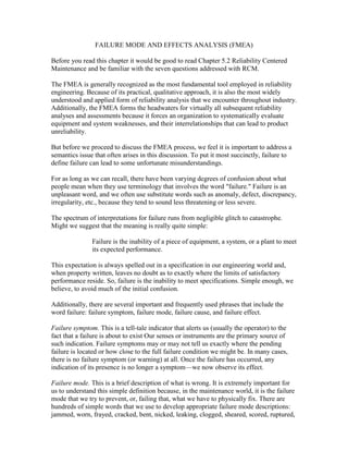
- 5. Figure 5.3.1 Simple Circuit Schematic.