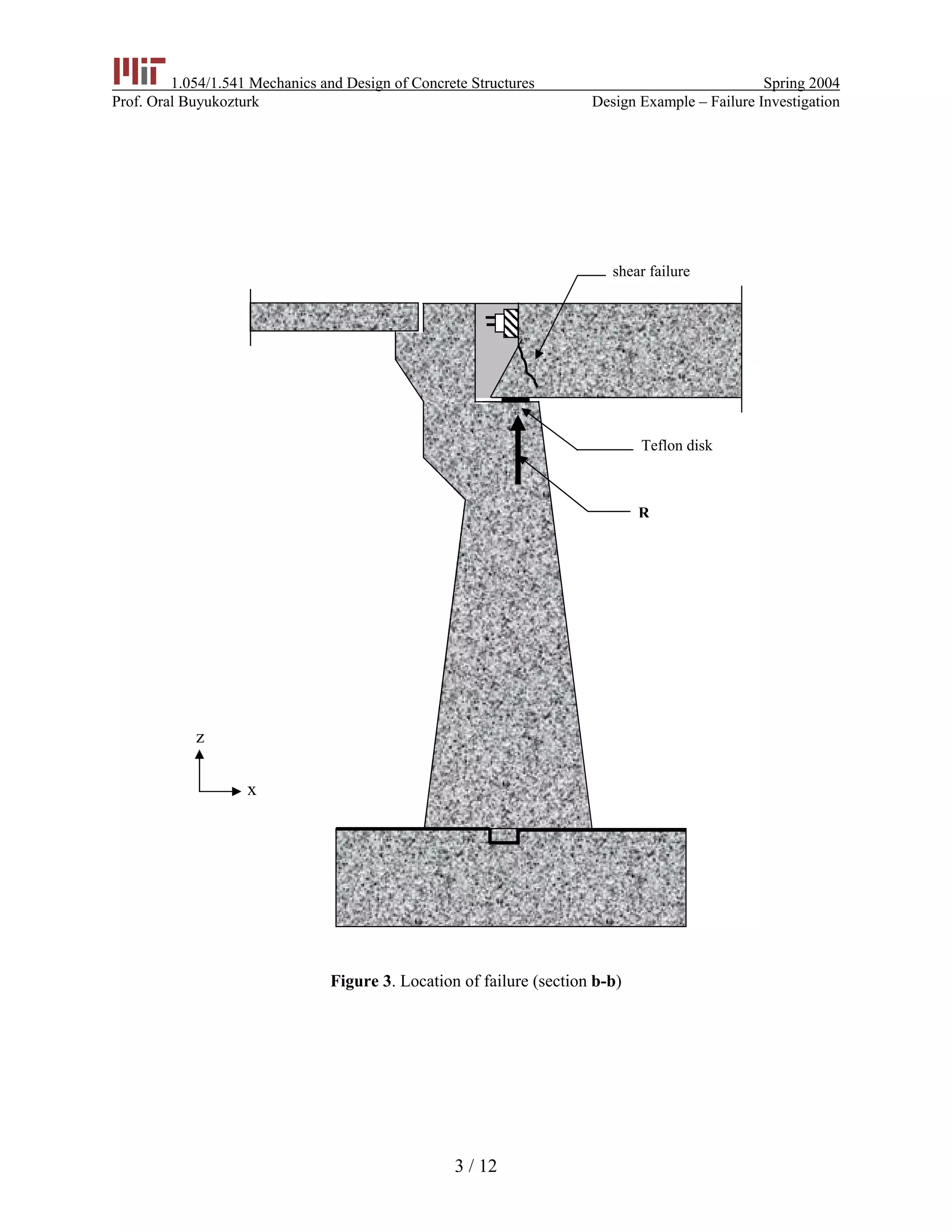
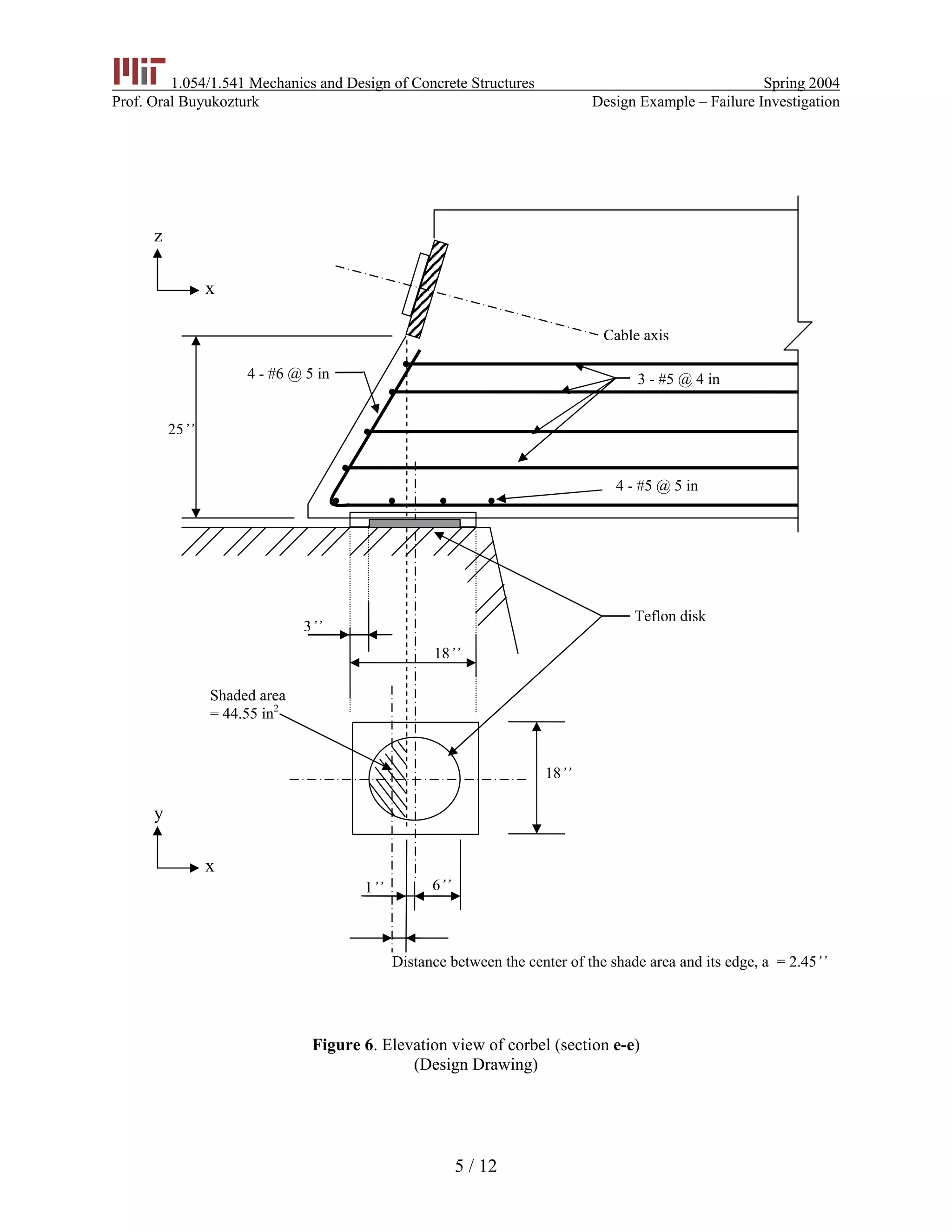
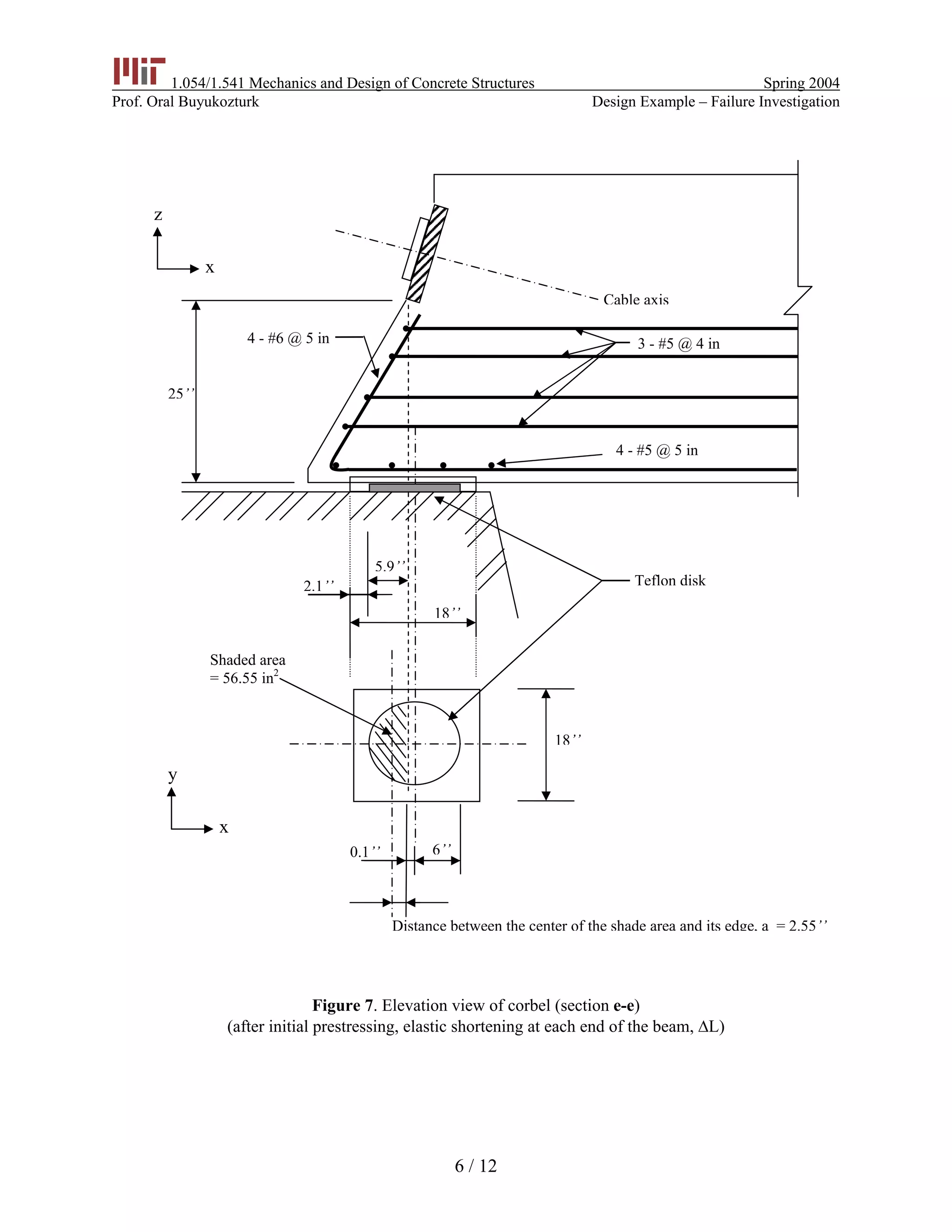
1.054/1.541 Mechanics and Design of Concrete Structures Spring 2004
Prof. Oral Buyukozturk Design Example – Failure Investigation
1 / 12
Massachusetts Institute of Technology
1.054/1.541 Mechanics and Design of Concrete Structures (3-0-9)
Design Example
Failure Investigation of A Prestressed
Concrete Bridge Girder
Objective: To investigate the failure of a prestressed girder in accordance with ACI 318-02.
Problem: A highway overpass consists of 3 parallel continuous prestressed concrete beams. The
length of the overpass structure is 292.8 ft, with a width of 47 ft (Fig. 1 and 2). Each
prestressed beam had 5 strands of prestressing steel. There were 22 wires in each
strand and each wire had a diameter of 0.6 in. The end of each prestressed beam was
supported by a corbel, which was inclined at an angle with respect to the bearing plate
(Fig. 3, 4, and 5).
Construction proceeded as planned: the beams were cast-in-place, and after the
concrete hardened, they were post-tensioned. Minutes after the prestressing operation,
4 out of the 6 corbels broke (Fig. 3). The State Transportation Authority decided to
determine the responsible parties involved in this failure case.
Task: You are hired to be the expert witness on the case. The following information were
established:
(a) The reaction force (R) at each end of the beam right before the collapse was
estimated at 275 kips.
(b) The horizontal restraint offered by the bearing (i.e., the Teflon disk) is negligible.
(c) Normal weight concrete was used with the compressive strength of fc
’
= 5000 psi.
(d) Yield stress for normal reinforcement was fy = 60 ksi.
Using the above information and the attached drawings, you are asked to assess and
testify on the following questions:
(1) Was the design (Fig. 6) adequate in accordance with ACI code requirements?
(2) It was reported that the elastic shortening of the beam due to the initial
prestressing was 0.9 in (Fig. 7). Check the design adequacy for this situation.
(3) It is postulated that the workmen might have placed the Teflon disk in the wrong
position initially. Together with the elastic shortening due to prestressing, the
final position of the Teflon disk was as shown in Fig. 8. Check the design again
using the ACI code.
(4) Based on the above information, give your opinion as to the cause(s) of the
collapse. It was argued that if instead of having the corbels, the prestressed beams
were cast into the piers as a whole unit (i.e., fixed ends), and then the failure
would not have occurred. Do you foresee any problems with this design?
1.054/1.541 Mechanics and Design of Concrete Structures Spring 2004
Prof. Oral Buyukozturk Design Example – Failure Investigation
`
B3
B2
B1
a
a
sym.
c
y
S1 =50o
c
b b
x
58.8‘ 117‘117‘
Figure 1. Plan view of overpass
z
y
9.25‘
0.75‘
2% grade
5.5‘5‘13‘
sym.
Figure 2. Cross section of overpass (section a-a)
2 / 12
1.054/1.541 Mechanics and Design of Concrete Structures Spring 2004
Prof. Oral Buyukozturk Design Example – Failure Investigation
z
x
Teflon disk
R
shear failure
Figure 3. Location of failure (section b-b)
3 / 12
1.054/1.541 Mechanics and Design of Concrete Structures Spring 2004
Prof. Oral Buyukozturk Design Example – Failure Investigation
Figure 4. End zone detail for prestressed beam (section c-c)
Figure 5. Plan view of end zone (section d-d)
dd
e
e
prestressing
steel anchor
corbel
sym.
z
y
x
y
beam axis
cable axis
cable axis
4 - #6
18’’
5’
sym.
4 / 12
1.054/1.541 Mechanics and Design of Concrete Structures Spring 2004
Prof. Oral Buyukozturk Design Example – Failure Investigation
z
x
x
4 - #5 @ 5 in
3 - #5 @ 4 in
Teflon disk
Cable axis
4 - #6 @ 5 in
25’’
Shaded area
= 44.55 in2
6’’1’’
Distance between the center of the shade area and its edge, a = 2.45’’
18’’
3’’
18’’
y
Figure 6. Elevation view of corbel (section e-e)
(Design Drawing)
5 / 12
1.054/1.541 Mechanics and Design of Concrete Structures Spring 2004
Prof. Oral Buyukozturk Design Example – Failure Investigation
z
x
4 - #5 @ 5 in
3 - #5 @ 4 in
Cable axis
4 - #6 @ 5 in
25’’
Shaded area
= 56.55 in2
6’’0.1’’
Distance between the center of the shade area and its edge, a = 2.55’’
2.1’’
5.9’’
18’’
18’’
Teflon disk
y
x
Figure 7. Elevation view of corbel (section e-e)
(after initial prestressing, elastic shortening at each end of the beam, ∆L)
6 / 12
1.054/1.541 Mechanics and Design of Concrete Structures Spring 2004
Prof. Oral Buyukozturk Design Example – Failure Investigation
z
x
Teflon disk
x
4 - #5 @ 5 in
3 - #5 @ 4 in
Shaded area
= 78.9 in2
Distance between the center of the shade area and its edge, a = 3.56’’
18’’
18’’
4 - #6 @ 5 in
25’’
Cable axis
y
Figure 8. Elevation view of corbel (section e-e)
(Postulate failure configuration)
7 / 12
1.054/1.541 Mechanics and Design of Concrete Structures Spring 2004
Prof. Oral Buyukozturk Design Example – Failure Investigation
(I) Engineering Drawing: ACI
Load on the corbel
– reaction R = 275 kips
– factored reaction Ru = 1.4 R = 385 kips
– area of Teflon disk A = ( )
2
12
4
π
⋅ = 113.1 in2
– uniform stress on the Teflon disk σu = uR
A
= 3.4 ksi
– shaded area A’ = 44.55 in2
– shear force Vu = uσ A⋅ ’ = 151.5 kips
– tension Nuc = 0 kips 11.9.3.4
– moment Mu = uV a⋅ 11.9.3.2
= 151.5 x 2.45
= 371.2 kips-in
Corbel dimension
h = 25 in
d = 25 – 2 = 23 in
bw = 18 in
a 2.45
= 0.107 1.0
d 23
= < (O.K.)
and Nuc < Vu 11.9.1
d1 =
5
23 = 11.5
10
⋅ in 0. (O.K.) 11.9.25d≥
Shear design
u
n
V 151.5
V = = = 202 kips
0.75φ
11.9.3.1
since max Vn = w0.2 b dcf ′⋅ ⋅ ⋅ 11.9.3.2.1
= 0.2 5 18 23 414 kips⋅ ⋅ ⋅ =
max Vn = w800 b d⋅ ⋅
= 800 18 23 331.2 kips⋅ ⋅ = (governs)
8 / 12
1.054/1.541 Mechanics and Design of Concrete Structures Spring 2004
Prof. Oral Buyukozturk Design Example – Failure Investigation
nV = 202 < 331.2 kips (O.K.)
1.4µ λ= ⋅ = 1.4 11.7.4.3
Vn = vfA yf µ⋅ ⋅ 11.9.3.2
vf
202
A 2
60 1.4
= = .4
⋅
in2
11.7.4.1
Flexural design
u wM = 0.85 b d-
2
c
x
f xφ
⎛ ⎞′⋅ ⋅ ⋅ ⋅ ⋅⎜ ⎟
⎝ ⎠
10.2.10
371.2 = 0.9 0.85 5 18 23-
2
x
x
⎛ ⎞
⋅ ⋅ ⋅ ⋅ ⋅⎜ ⎟
⎝ ⎠
setting x = 0.3
f wA 0.85 bcf x′= ⋅ ⋅ ⋅
= 0.383 in2
Tension design
Since Nuc = 0 11.9.3.4
An = 0
Primary tension reinforcement
As = Af + An = 0.383 in2
11.9.3.5
or vf n
2
A A 1.41
3
+ = in2
(governs)
From the design, there are 4 - #6 bars provided.
(As)provided = 4 0.44⋅ in2
= 1.76 in2
> 1.41 in2
(O.K.)
Ties
( )n sA 0.5 A A≥ ⋅ − n 11.9.4
( )0.5 1.41 0≥ ⋅ −
in0.71≥ 2
From the design, over
2
d = 15.33 in
3
, there are 3 - #5 bars provided.
9 / 12
1.054/1.541 Mechanics and Design of Concrete Structures Spring 2004
Prof. Oral Buyukozturk Design Example – Failure Investigation
(An)provided = 3 2 0.31× ×
= 1.86 in2
> 0.71 in2
(O.K.)
Reinforcement ratio
sA 1.76
0.0043
b d 18 23
ρ = = =
⋅ ⋅
11.9.5
5
0.04 0.04 0.0033 0.0043
60
c
y
f
f
′
⋅ = ⋅ = < (O.K.)
⇒ The engineering design in Fig. 6 is adequate in accordance with ACI code 318-02.
(II) With elastic shortening
Similarly, we have A’ = 56.55 in2
Vu = 3.4 56.55 192.3⋅ = kips
Nuc = 0
Mu = uV a⋅
= 192.3 2.55⋅
= 490.8 kips-in
Corbel dimension
a 2.55
0.111 0.5
d 23
= = < (O.K.)
1
4.1 d
d 23 9.43
10 2
= ⋅ = < (N.G.)
Shear design
u
n
V 192.3
V 257.6 kips < 331.2 kips
0.75φ
= = = (O.K.)
11.9.3.2
2
vf
257.6
A 3.
60 1.4
= = 07 in
×
Flexural design
nM d
2
c
x
f bxφ
⎛ ⎞′= −⎜ ⎟
⎝ ⎠
10 / 12
1.054/1.541 Mechanics and Design of Concrete Structures Spring 2004
Prof. Oral Buyukozturk Design Example – Failure Investigation
490.8 0.9 0.85 5 18 23
2
x
x
⎛ ⎞
= × × × × × −⎜ ⎟
⎝ ⎠
x = 0.316 in⇒
A⇒ f = 0.40 in2
Primary tension reinforcement
2
s f nA A +A 0.40 in= =
or 2
s vf n
2
A A +A 2.04 in
3
= = (governs)
Since (As)provided = (N.G.)2 2
1.76 in < 2.04 in
(An)provided = 2 2sA 2.04
1.86 in > = = 1.02 in
2 2
(O.K.)
⇒ With elastic shortening of 0.9 in, the given design is not adequate.
(III) With shortening and misplaced Teflon disk
Similarly, A’ = 78.9 in2
Vu = 3.4 78.9 268.3× = kips
Nuc = 0
Mu = uV a×
= 268.3 3.56×
= 955 kips-in
Corbel dimension
a 3.56
0.155 1
d 23
= = < (O.K.)
1
2 d
d 23 4.6 in
10 2
= × = < (N.G.)
Shear design
u
n
V 268.3
V 357.7 kips > 331.2 kips
0.75φ
= = = (N.G.)
2
vf
357.7
A 4.
60 1.4
= =
×
26 in (O.K.) 11.9.3.2
Flexural design
11 / 12
1.054/1.541 Mechanics and Design of Concrete Structures Spring 2004
Prof. Oral Buyukozturk Design Example – Failure Investigation
nM d
2
c
x
f bxφ
⎛ ⎞′= −⎜ ⎟
⎝ ⎠
955 0.9 0.85 5 18 23
2
x
x
⎛ ⎞
= × × × × × −⎜ ⎟
⎝ ⎠
x = 0.62 in⇒
A⇒ f = 0.79 in2
Primary tension reinforcement
2
s f nA A +A 0.79 in= =
or 2
s vf n
2
A A +A 2.84 in
3
= = (governs)
Since (As)provided = (N.G.)2 2
1.76 in < 2.84 in
(An)provided = 2 2sA 2.84
1.86 in > = =1.42 in
2 2
(O.K.)
⇒ With misplacement of Teflon disk and elastic shortening, the given design is not
adequate.
(IV) There is a good chance that the failure was due to poor design or inadequate
considerations on the part of engineer. Even if the Teflon disk was correctly placed,
with the elastic shortening of beam and live loads, the bridge does not have much of a
chance of surviving. Misplacement of the Teflon disk greatly increased the risk of
failure since no information on the site supervision on the pat of the engineer was given.
A probable cause of the failure could then be attributed to both the engineer and the
contractor.
If the beam is cast monolithically into the pier, problems that might arise are
– Secondary stresses induced die to creep, shrinkage and elastic shortening;
– Thermal stresses created due to differential temperature effect.
12 / 12

Failure investigation of prestressed bridge girder

  • 1.
    1.054/1.541 Mechanics andDesign of Concrete Structures Spring 2004 Prof. Oral Buyukozturk Design Example – Failure Investigation 1 / 12 Massachusetts Institute of Technology 1.054/1.541 Mechanics and Design of Concrete Structures (3-0-9) Design Example Failure Investigation of A Prestressed Concrete Bridge Girder Objective: To investigate the failure of a prestressed girder in accordance with ACI 318-02. Problem: A highway overpass consists of 3 parallel continuous prestressed concrete beams. The length of the overpass structure is 292.8 ft, with a width of 47 ft (Fig. 1 and 2). Each prestressed beam had 5 strands of prestressing steel. There were 22 wires in each strand and each wire had a diameter of 0.6 in. The end of each prestressed beam was supported by a corbel, which was inclined at an angle with respect to the bearing plate (Fig. 3, 4, and 5). Construction proceeded as planned: the beams were cast-in-place, and after the concrete hardened, they were post-tensioned. Minutes after the prestressing operation, 4 out of the 6 corbels broke (Fig. 3). The State Transportation Authority decided to determine the responsible parties involved in this failure case. Task: You are hired to be the expert witness on the case. The following information were established: (a) The reaction force (R) at each end of the beam right before the collapse was estimated at 275 kips. (b) The horizontal restraint offered by the bearing (i.e., the Teflon disk) is negligible. (c) Normal weight concrete was used with the compressive strength of fc ’ = 5000 psi. (d) Yield stress for normal reinforcement was fy = 60 ksi. Using the above information and the attached drawings, you are asked to assess and testify on the following questions: (1) Was the design (Fig. 6) adequate in accordance with ACI code requirements? (2) It was reported that the elastic shortening of the beam due to the initial prestressing was 0.9 in (Fig. 7). Check the design adequacy for this situation. (3) It is postulated that the workmen might have placed the Teflon disk in the wrong position initially. Together with the elastic shortening due to prestressing, the final position of the Teflon disk was as shown in Fig. 8. Check the design again using the ACI code. (4) Based on the above information, give your opinion as to the cause(s) of the collapse. It was argued that if instead of having the corbels, the prestressed beams were cast into the piers as a whole unit (i.e., fixed ends), and then the failure would not have occurred. Do you foresee any problems with this design?
  • 2.
    1.054/1.541 Mechanics andDesign of Concrete Structures Spring 2004 Prof. Oral Buyukozturk Design Example – Failure Investigation ` B3 B2 B1 a a sym. c y S1 =50o c b b x 58.8‘ 117‘117‘ Figure 1. Plan view of overpass z y 9.25‘ 0.75‘ 2% grade 5.5‘5‘13‘ sym. Figure 2. Cross section of overpass (section a-a) 2 / 12
  • 3.
    1.054/1.541 Mechanics andDesign of Concrete Structures Spring 2004 Prof. Oral Buyukozturk Design Example – Failure Investigation z x Teflon disk R shear failure Figure 3. Location of failure (section b-b) 3 / 12
  • 4.
    1.054/1.541 Mechanics andDesign of Concrete Structures Spring 2004 Prof. Oral Buyukozturk Design Example – Failure Investigation Figure 4. End zone detail for prestressed beam (section c-c) Figure 5. Plan view of end zone (section d-d) dd e e prestressing steel anchor corbel sym. z y x y beam axis cable axis cable axis 4 - #6 18’’ 5’ sym. 4 / 12
  • 5.
    1.054/1.541 Mechanics andDesign of Concrete Structures Spring 2004 Prof. Oral Buyukozturk Design Example – Failure Investigation z x x 4 - #5 @ 5 in 3 - #5 @ 4 in Teflon disk Cable axis 4 - #6 @ 5 in 25’’ Shaded area = 44.55 in2 6’’1’’ Distance between the center of the shade area and its edge, a = 2.45’’ 18’’ 3’’ 18’’ y Figure 6. Elevation view of corbel (section e-e) (Design Drawing) 5 / 12
  • 6.
    1.054/1.541 Mechanics andDesign of Concrete Structures Spring 2004 Prof. Oral Buyukozturk Design Example – Failure Investigation z x 4 - #5 @ 5 in 3 - #5 @ 4 in Cable axis 4 - #6 @ 5 in 25’’ Shaded area = 56.55 in2 6’’0.1’’ Distance between the center of the shade area and its edge, a = 2.55’’ 2.1’’ 5.9’’ 18’’ 18’’ Teflon disk y x Figure 7. Elevation view of corbel (section e-e) (after initial prestressing, elastic shortening at each end of the beam, ∆L) 6 / 12
  • 7.
    1.054/1.541 Mechanics andDesign of Concrete Structures Spring 2004 Prof. Oral Buyukozturk Design Example – Failure Investigation z x Teflon disk x 4 - #5 @ 5 in 3 - #5 @ 4 in Shaded area = 78.9 in2 Distance between the center of the shade area and its edge, a = 3.56’’ 18’’ 18’’ 4 - #6 @ 5 in 25’’ Cable axis y Figure 8. Elevation view of corbel (section e-e) (Postulate failure configuration) 7 / 12
  • 8.
    1.054/1.541 Mechanics andDesign of Concrete Structures Spring 2004 Prof. Oral Buyukozturk Design Example – Failure Investigation (I) Engineering Drawing: ACI Load on the corbel – reaction R = 275 kips – factored reaction Ru = 1.4 R = 385 kips – area of Teflon disk A = ( ) 2 12 4 π ⋅ = 113.1 in2 – uniform stress on the Teflon disk σu = uR A = 3.4 ksi – shaded area A’ = 44.55 in2 – shear force Vu = uσ A⋅ ’ = 151.5 kips – tension Nuc = 0 kips 11.9.3.4 – moment Mu = uV a⋅ 11.9.3.2 = 151.5 x 2.45 = 371.2 kips-in Corbel dimension h = 25 in d = 25 – 2 = 23 in bw = 18 in a 2.45 = 0.107 1.0 d 23 = < (O.K.) and Nuc < Vu 11.9.1 d1 = 5 23 = 11.5 10 ⋅ in 0. (O.K.) 11.9.25d≥ Shear design u n V 151.5 V = = = 202 kips 0.75φ 11.9.3.1 since max Vn = w0.2 b dcf ′⋅ ⋅ ⋅ 11.9.3.2.1 = 0.2 5 18 23 414 kips⋅ ⋅ ⋅ = max Vn = w800 b d⋅ ⋅ = 800 18 23 331.2 kips⋅ ⋅ = (governs) 8 / 12
  • 9.
    1.054/1.541 Mechanics andDesign of Concrete Structures Spring 2004 Prof. Oral Buyukozturk Design Example – Failure Investigation nV = 202 < 331.2 kips (O.K.) 1.4µ λ= ⋅ = 1.4 11.7.4.3 Vn = vfA yf µ⋅ ⋅ 11.9.3.2 vf 202 A 2 60 1.4 = = .4 ⋅ in2 11.7.4.1 Flexural design u wM = 0.85 b d- 2 c x f xφ ⎛ ⎞′⋅ ⋅ ⋅ ⋅ ⋅⎜ ⎟ ⎝ ⎠ 10.2.10 371.2 = 0.9 0.85 5 18 23- 2 x x ⎛ ⎞ ⋅ ⋅ ⋅ ⋅ ⋅⎜ ⎟ ⎝ ⎠ setting x = 0.3 f wA 0.85 bcf x′= ⋅ ⋅ ⋅ = 0.383 in2 Tension design Since Nuc = 0 11.9.3.4 An = 0 Primary tension reinforcement As = Af + An = 0.383 in2 11.9.3.5 or vf n 2 A A 1.41 3 + = in2 (governs) From the design, there are 4 - #6 bars provided. (As)provided = 4 0.44⋅ in2 = 1.76 in2 > 1.41 in2 (O.K.) Ties ( )n sA 0.5 A A≥ ⋅ − n 11.9.4 ( )0.5 1.41 0≥ ⋅ − in0.71≥ 2 From the design, over 2 d = 15.33 in 3 , there are 3 - #5 bars provided. 9 / 12
  • 10.
    1.054/1.541 Mechanics andDesign of Concrete Structures Spring 2004 Prof. Oral Buyukozturk Design Example – Failure Investigation (An)provided = 3 2 0.31× × = 1.86 in2 > 0.71 in2 (O.K.) Reinforcement ratio sA 1.76 0.0043 b d 18 23 ρ = = = ⋅ ⋅ 11.9.5 5 0.04 0.04 0.0033 0.0043 60 c y f f ′ ⋅ = ⋅ = < (O.K.) ⇒ The engineering design in Fig. 6 is adequate in accordance with ACI code 318-02. (II) With elastic shortening Similarly, we have A’ = 56.55 in2 Vu = 3.4 56.55 192.3⋅ = kips Nuc = 0 Mu = uV a⋅ = 192.3 2.55⋅ = 490.8 kips-in Corbel dimension a 2.55 0.111 0.5 d 23 = = < (O.K.) 1 4.1 d d 23 9.43 10 2 = ⋅ = < (N.G.) Shear design u n V 192.3 V 257.6 kips < 331.2 kips 0.75φ = = = (O.K.) 11.9.3.2 2 vf 257.6 A 3. 60 1.4 = = 07 in × Flexural design nM d 2 c x f bxφ ⎛ ⎞′= −⎜ ⎟ ⎝ ⎠ 10 / 12
  • 11.
    1.054/1.541 Mechanics andDesign of Concrete Structures Spring 2004 Prof. Oral Buyukozturk Design Example – Failure Investigation 490.8 0.9 0.85 5 18 23 2 x x ⎛ ⎞ = × × × × × −⎜ ⎟ ⎝ ⎠ x = 0.316 in⇒ A⇒ f = 0.40 in2 Primary tension reinforcement 2 s f nA A +A 0.40 in= = or 2 s vf n 2 A A +A 2.04 in 3 = = (governs) Since (As)provided = (N.G.)2 2 1.76 in < 2.04 in (An)provided = 2 2sA 2.04 1.86 in > = = 1.02 in 2 2 (O.K.) ⇒ With elastic shortening of 0.9 in, the given design is not adequate. (III) With shortening and misplaced Teflon disk Similarly, A’ = 78.9 in2 Vu = 3.4 78.9 268.3× = kips Nuc = 0 Mu = uV a× = 268.3 3.56× = 955 kips-in Corbel dimension a 3.56 0.155 1 d 23 = = < (O.K.) 1 2 d d 23 4.6 in 10 2 = × = < (N.G.) Shear design u n V 268.3 V 357.7 kips > 331.2 kips 0.75φ = = = (N.G.) 2 vf 357.7 A 4. 60 1.4 = = × 26 in (O.K.) 11.9.3.2 Flexural design 11 / 12
  • 12.
    1.054/1.541 Mechanics andDesign of Concrete Structures Spring 2004 Prof. Oral Buyukozturk Design Example – Failure Investigation nM d 2 c x f bxφ ⎛ ⎞′= −⎜ ⎟ ⎝ ⎠ 955 0.9 0.85 5 18 23 2 x x ⎛ ⎞ = × × × × × −⎜ ⎟ ⎝ ⎠ x = 0.62 in⇒ A⇒ f = 0.79 in2 Primary tension reinforcement 2 s f nA A +A 0.79 in= = or 2 s vf n 2 A A +A 2.84 in 3 = = (governs) Since (As)provided = (N.G.)2 2 1.76 in < 2.84 in (An)provided = 2 2sA 2.84 1.86 in > = =1.42 in 2 2 (O.K.) ⇒ With misplacement of Teflon disk and elastic shortening, the given design is not adequate. (IV) There is a good chance that the failure was due to poor design or inadequate considerations on the part of engineer. Even if the Teflon disk was correctly placed, with the elastic shortening of beam and live loads, the bridge does not have much of a chance of surviving. Misplacement of the Teflon disk greatly increased the risk of failure since no information on the site supervision on the pat of the engineer was given. A probable cause of the failure could then be attributed to both the engineer and the contractor. If the beam is cast monolithically into the pier, problems that might arise are – Secondary stresses induced die to creep, shrinkage and elastic shortening; – Thermal stresses created due to differential temperature effect. 12 / 12