Individual
•Download as DOC, PDF•
1 like•136 views

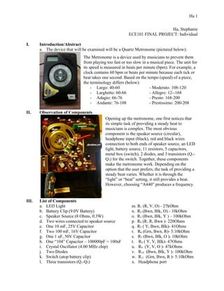
The metronome uses electronic components to provide a steady beat or tone for musicians. When the switch is turned on, the battery powers the circuit. Depending on the switch setting, different components work together to produce sound from the speaker or LED flashes. In the "beat" setting, the crystal oscillator sends a signal through transistors and resistors to the speaker or headphones at the set tempo. The "A440" setting produces a high A note, and "lamp" only flashes the LED. Together these components allow the metronome to keep time for musicians through visual or audio cues.

Recommended
More Related Content
What's hot
What's hot (20)
Similar to Individual
Similar to Individual (20)
More from Stephanie Ha
More from Stephanie Ha (8)
Individual
- 1. Ha, Stephanie ECE101 FINAL PROJECT: Individual I. Introduction/Abstract a. The device that will be examined will be a Quartz Metronome (pictured below): II. Observation of Components III. List of Components a. LED Light m. R1 (R, V, O) - 27kOhm b. Battery Clip (9.0V Battery) n. R2 (Bwn, Blk, O) - 10kOhm c. Speaker Source (8 Ohms, 0.3W) o. R3 (Bwn, Blk, Y ) – 100kOhm d. Two wires connected to speaker source p. R4 (R, R, Bwn )- 220Ohms e. One 10 mF, 25V Capacitor q. R5 ( Y, Bwn, Blk)- 41Ohms f. Two 100 mF, 16V Capacitor r. R6 (Grn, Bwn, R)- 5.10kOhm g. One 1 uF, 50V Capacitor s. R7 (Bwn, Blk, O )- 10kOhm h. One “104” Capacitor – 100000pF = 100nF t. R8 ( Y, V, Blk)- 47Ohms i. Crystal Oscillator (4.00 MHz chip) u. R9 (Y, V, O )- 47kOhms j. Two Diodes v. R10 (Bwn, Blk, Y )- 100kOhm k. Switch (atop battery clip) w. R11 (Grn, Bwn, R )- 5.10kOhm l. Three transistors (Q1-Q3) x. Headphone port Ha 1 The Metronome is a device used by musicians to prevent them from playing too fast or too slow in a musical piece. The unit for its speed is measured in beats per minute (bpm). For example, a clock contains 60 bpm or beats per minute because each tick or beat takes one second. Based on the tempo (speed) of a piece, the terminology differs (below): - Largo: 40-60 - Moderato: 108-120 - Larghetto: 60-66 - Allegro: 12--168 - Adagio: 66-76 - Presto: 168-200 - Andante: 76-108 - Prestissimo: 200-208 Opening up the metronome, one first notices that its simple task of providing a steady beat to musicians is complex. The most obvious component is the speaker source (circular), headphone input (black), red and black wires connection to both ends of speaker source, an LED light, battery source, 11 resistors, 5 capacitors, metal box (switch), 2 diodes, and 3 transistors (Q1- Q3) for the switch. Together, these components make the metronome work. Depending on the option that the user prefers, the task of providing a steady beat varies. Whether it is through the “light” or “beat” setting, it still provides a beat. However, choosing “A440” produces a frequency.
- 2. III. How Components Work Together a. What each component does i. LED Light – If the user selects an option of “lamp” or “beat” on the switch, the LED light will blink red with whichever beat the user selects. ii. Battery Clip (9.0V battery) – It acts as the power supply to power the metronome. If there is no battery in the battery clip, it won’t work. iii. Speaker Source (8 Ohms, 0.3W) – The speaker source sends out a beat if the ”beat” option is selected or plays the note, A in 440 Hz if the option “A440” is selected. In other words, it outputs sound to the user. The beat that is heard allows the musician/user to stay in tempo/time with the speed of the music he or she is playing. Meanwhile, “A440” outputs a note, A for the musician to tune his or her instrument. iv. Two wires (red and black) connected to speaker source 1. Red wire - outputs a sound when the “up” knob is pressed 2. Black wire – outputs a sound when the “down” knob is pressed v. One 10 mF, 25V Capacitor (C8) – Stores charge for A440 setting vi. Two 100mF, 16V Capacitor (C1, C2) 1. C1 – Stores charge for speaker source 2. C2 – Stores charge for A440 vii. One 1 uF, 50V Capacitor (C44) – Stores the charge for headphone port viii. One “104 (100nF )” Capacitor – Stores the electrical charge for LED light ix. Crystal Oscillator (4.00MHz) – It acts as an “internal clock” to provide a consistent frequency through a vibrating crystal to display the tempo (speed) that the user selects. The “up” knob increases speed, while the “down” decreases it. x. Two Diodes – The diodes allow current to flow in one direction which in turn, reduces the voltage across a resistor. In other words, the flow of energy is restricted/limited when a diode is used. xi. Switch (atop battery clip) – There are 4 different settings on the switch: “A440”, “LAMP”, “BEAT”, and “OFF” xii. Three transistors (Q1-Q3) – Each transistor acts as a switch for a setting. 1. Q1 – Switch for “BEAT” Produces a beat and a blinking LED light 2. Q2 – Switch for “LAMP” Only LED light blinks 3. Q3 – Switch for “A440” Outputs a high-pitch noise through speaker 4. When the switch is “OFF”, voltage does not go through any transistor. xiii. R1, R7, R8 – Connected in parallel, next to 1uF capacitor for A440 setting xiv. R2 R6 – Connected in parallel, next to Q2, Q3, and D2. Resistors for setting of “LAMP” and “BEAT” xv. R4, R9, R10, R3 – These resistors are connected in a series fashion to limit the amount of current that goes through the LED light. xvi. R5 – Allows current to pass for headphone input if a headphone is plugged there. xvii. R11 – Designated for the knob functions (front). When this is pressed, the tempo either decreases (“down” knob) or increases (“up” knob) is pressed. As a result, the number outputted by the crystal oscillator either decreases or increases until a desired tempo is accepted by the user (when knobs are not pressed). xviii. Headphone port – The beat will flow out into the headphones instead of the speaker source if there is a headphone plugged in. Valid for BEAT and A440. Ha 2
- 3. b. How they work together i. Depending on whichever position the switch is in, each component functions differently since there are four different types of tasks possible (refer below). 1. Initially, the switch is in the “OFF” position. When this is true, no current and voltage passes through the resistors and diodes. Likewise, the crystal oscillator is blank. In other words, no value is shown on the display stored in the “internal clock” of the oscillator. 2. However, when the switch is in the “A440” position, there is no data stored in the crystal oscillator and the LED light is off. Only a piercing high-note of A in 440Hz is played. In order to produce this sound, the signal/setting is transmitted through Q3. Q3 then goes through C2 and C8 to allow current and voltage to flow through R7. 3. If the switch is in the “LAMP” position, only the LED light and tempo (speed) will be displayed. No beat will be produced. In order for this to work, C5 supplies the charge to the LED light in which current and voltage is passed through R4, R9, R10, and R3. Therefore, no current will pass through the other resistors. Since the crystal oscillator is independent of all the electrical components, it is an electric circuit that acts on the vibrating crystal to keep track of the tempo that the user selects. 4. If the switch is in the “BEAT” position, the stored beat from the oscillator will be outputted to either the speaker source of the headphone port, if there is a headphone plugged into it. Current and voltage is provided by D2, R2, and R6. a. *Note: battery source has two terminals: an anode and a cathode which are connected to the ground. The same case goes for the arrangement for the speaker source. Ha 3