This document provides instructions and specifications for bumpers and frames on an XJ vehicle. It includes sections on removing and installing various bumper components like end caps, the front and rear bumpers, and tow hooks. It also covers removing and installing skid plates and describes vehicle dimensions and frame torque specifications.
The document discusses the frame and bumpers of the Jeep Grand Cherokee. It notes that the Grand Cherokee does not have a conventional frame, but rather a unitized body and frame construction made of high-strength steel. It describes how to diagnose collision damage and properly repair a unibody structure. The document provides removal and installation instructions for the front and rear bumpers, as well as the front and rear tow hooks. Measurement points for the frame are also indicated to ensure proper alignment during repair.
The document discusses the exhaust system and intake manifold of an XJ vehicle. It provides information on general components of the exhaust system, removal and installation of the exhaust pipe, muffler and tailpipe. It also describes removal and installation of the engine exhaust manifold and turbocharger. Key steps and torque specifications are outlined for servicing these components.
This document provides removal and installation instructions for various lamps on a vehicle, including headlights, front turn signals, fog lamps, taillights, and interior lamps. Specifications are given for replacement bulb types for interior lamps. Removal involves removing bezels, housings, or sockets, and bulbs are replaced by twisting or pulling them from the socket. Installation is the reverse of removal.
1) The document provides assembly instructions for the Prismasonic Ceiling Mount CB-200, listing all included parts and explaining how to attach the projector and lens to the mount.
2) It describes connecting the universal base plate to the projector in different ways depending on its center of gravity, then attaching extension rods and connecting the assembly to the ceiling plate.
3) Final steps include inserting logo plates and optionally direct mounting to the ceiling plate without extension rods for minimum drop from the ceiling. Precise assembly is emphasized for stability and safety.
This document is an instruction manual for C-MORE Railway red dot sighting systems. It includes details on package contents, operating instructions, zeroing procedures, maintenance and warranty information. The manual provides concise instructions on installing the sight, adjusting settings like brightness and windage/elevation, replacing batteries and diode modules, and basic maintenance steps.
This document provides an overview and instructions for point detonating (PD) and variable time (VT) fuzes used in 155mm ammunition. It describes the components and functioning of common PD fuzes, including the MASKED and MASKED. It also outlines the components, special handling requirements, time setting, and functioning of VT fuzes like the MASKED and MASKED. The VT fuze uses radar to detonate a projectile at a specific distance from its target, while PD fuzes detonate on contact or with a slight delay.
Photochromic glass darkens when exposed to light and reverts to transparency when the light is dim. It contains silver chloride that reacts reversibly to light. Such properties make photochromic glass suitable for use in optical lenses, car windshields, and smart energy efficient windows.
Guest Speaker @ SAE Noise & Vibration ConferenceJohn Long
This document summarizes John T. Long's presentation on future trends in vehicle sound packages. It discusses how automakers are bringing acoustic integration expertise in-house after outsourcing it. Tier 1 and 2 suppliers will need to meet automakers' NVH targets and conduct testing to remain competitive. The document also notes that automakers will seek lightweight acoustic materials, especially from niche suppliers using technologies like nanotechnology. Emerging technologies like active noise control and requirements for alternative fuel vehicles will create new material demands. Regulations on exterior noise are expected to increase in North America, and interior noise standards will be important for voice recognition systems.
An overview of a few special materials, most of which are available commercially and can be used on DIY projects. All images and "+ info @ ..." on the slideshow are linked to the corresponding resources or projects' websites.
Smart materials called shape memory alloys have the ability to retain their original shape after deformation at a transition temperature. Some types of smart materials include piezoelectric materials, thermochromic materials, photochromic materials, and magnetorheological fluids. Shape memory alloys made of nickel-titanium, copper-zinc-aluminum, and gold-cadmium can return to their original shape after being deformed by heating. These alloys find applications in industries like engineering, healthcare, aerospace, and home appliances.
Composite materials are formed by combining two or more materials. Concrete reinforced with steel wires or polymer fibers is an example of a composite that is strong and has more tensile strength than its components alone. Superconductors made of metal alloys or ceramic metal oxides are used in bullet trains and MRI machines. Fiber optic cable transmits data and is made of glass or plastic fibers surrounded by glass cladding. Fiber glass combines glass fibers with plastic to create a strong yet low density material used in boats, helmets, and tanks. Photochromic glass changes darkness when exposed to light and is used in lenses and windows.
Building service.ppt of neeru and aprajeetativar rose
This document discusses building acoustics and provides solutions for acoustic defects. It begins with definitions and characteristics of sound, including transmission, absorption, reflection, and reverberation. Common acoustic defects like echoes, reverberation, insufficient loudness, sound foci, and dead spots are described along with solutions. Various acoustic materials are presented with applications and coefficients. A case study of a hotel demonstrates acoustic design considerations for reception, doors, furniture, ceilings, floors, and glazing.
This document discusses smart materials, which are materials that can significantly change one or more properties in response to external stimuli like stress, temperature, electric or magnetic fields in a controlled way. It classifies different types of smart materials like piezoelectric, shape memory alloys, thermochromic and discusses their input-output behavior and applications. Some key smart materials discussed are piezoelectric quartz, shape memory alloys used in aircraft and orthopedics, thermochromic inks and papers, photochromic lenses and electrochromic smart glass. The document concludes that smart materials react to their environment and can reversibly change properties, offering properties tunable at different scales with wide applications.
This document discusses various types of artifacts that can appear in ultrasound images, including reverberation, acoustic shadowing, enhancement, edge shadowing, beam width artifact, slice thickness artifact, side lobe artifact, mirror image, double image, and equipment-generated and refraction artifacts. It provides details on what causes each type of artifact and examples of when they may appear.
This document discusses architectural acoustics and provides information on sound classification, characteristics of musical sound, intensity, absorption coefficient, sound absorbing materials, reverberation, and factors affecting building acoustics such as reverberation time, loudness, focusing, echo, echelon effect, and resonance. It also covers noise control and discusses remedies for improving acoustics issues in buildings.
This document provides information on various sound insulation materials, including their characteristics, pricing, sizes, and intended uses. Glass mineral wool is made from recycled glass, limestone and soda ash to form fine strands that are bound together. It has good tear strength and is lightweight with low environmental impact. Rock mineral wool is made from volcanic rock and recycled slag, and has high compressive strength. It can be used for thermal insulation and fire protection. Foamed plastics like extruded polystyrene are made through an extrusion process and have high compressive strength, water resistance and freeze-thaw performance. Products like Quiet Batt and Studio Pro are high-performance sound absorbing insulation materials used residentially and commercially.
Underwater acoustic communication uses sound waves to transmit data underwater instead of electromagnetic waves. It allows remote control of underwater instruments and real-time data transmission. Examples include acoustic modems that convert digital data to sound signals, the Deep-ocean Assessment and Reporting of Tsunamis program's acoustic sensors that detect tsunamis, and robotic crawlers equipped with cameras and modems that can locate underwater objects and transmit images.
The document discusses various exterior body components of a vehicle. It provides removal and installation instructions for components like the grille, headlamps, hood, hood latches and related parts. The document is organized in sections covering the grille/reinforcement, radiator support, hood, hood hinges/latches/striker and other exterior parts. Diagrams and step-by-step instructions are provided for servicing these exterior body parts.
The document provides instructions for removing and installing clutch components on a vehicle. It describes the main clutch parts, including the clutch disc, clutch cover, pilot bearing, and flywheel. The steps for removal and installation of the clutch cover and disc, pilot bearing, and flywheel are outlined. Specifications for torque values and required tools are also listed.
This document provides instructions for replacing various parts on exercise equipment. It includes 3 procedures for replacing the swoosh covers, inner rocker assembly cover, and control link assembly. Each procedure lists the required tools, estimated time, and step-by-step instructions for removing the old part and installing the new one. Images and diagrams are included to illustrate the parts and assembly.
The document provides instructions for removing and installing a No. 2 back door name plate. It describes cleaning the name plate and vehicle body surface, heating them with a heat light, and removing the double-sided tape. It specifies the standard heating temperatures and measurement for installing the name plate. Precautions are given to install the name plate exactly according to the specifications and keep the adhesive free from foreign matter after removing the peeling paper.
This document provides instructions for removing and installing the generator and vacuum pump assembly on a 2.5L diesel engine. It begins with general information on the charging system and a test for the vacuum pump. The removal process involves disconnecting battery and electrical connections, removing hoses and mounting bolts, and draining oil before removing the assembly. Installation is the reverse of removal, ensuring proper belt routing and specified tightening of hardware.
Caterpillar cat 931 b track loader (prefix 30y) service repair manual (30y000...fujsefkxswksemm
This service repair manual provides instructions for removing and installing various components of a Caterpillar 931B track loader, including:
1) Track roller frames, which are removed by taking off guards, yokes, and bolts, and lifted with straps and a hoist.
2) Pivot shafts, by removing seals, bearings, and support assemblies after draining oil and using straps and hoists.
3) Equalizer bars, which are removed by taking off guards and pins after jacking up the machine.
Caterpillar cat 931 b track loader (prefix 30y) service repair manual (30y000...fujsekfkksemm
This document provides instructions for removing and installing various components of the track and power train system for a Caterpillar 931B track loader, including:
1. Removing and installing the track roller frames, which requires lifting them with straps and hoists due to their weight of 320 kg.
2. Removing and installing the pivot shaft, which involves removing seals and bearings from supporting assemblies and lubricating the shaft during installation.
3. Removing and installing the equalizer bar, which must be supported by a floor jack during removal and installation due to its weight of 100 kg.
4. Procedures for removing and installing sprocket segments and hubs, including using specialized tools to loosen
Caterpillar cat 931 b track loader (prefix 30y) service repair manual (30y000...fujsjefskekm
This document provides instructions for removing and installing various components of the track and power train systems for a Caterpillar 931B track loader, including:
1. Removing and installing the track roller frames, which requires lifting them with straps and hoists due to their weight of 320 kg.
2. Removing and installing the pivot shaft, which involves removing seals and bearings from supporting assemblies and lubricating the shaft during reinstallation.
3. Removing and installing the equalizer bar, which must be supported by a floor jack during removal and installation due to its weight of 100 kg.
4. Procedures for removing and installing sprocket segments and hubs, including using specialty tools to loose
Caterpillar cat 931 b track loader (prefix 30y) service repair manual (30y000...fjjskkdmnsme
This document provides instructions for removing and installing various components of the track and power train system on a Caterpillar 931B track loader, including:
1. Removing and installing the track roller frames, which requires lifting them with straps and hoists due to their weight of 320 kg.
2. Removing and installing the pivot shaft, which involves removing seals and bearings from supporting assemblies and lubricating the shaft during reinstallation.
3. Removing and installing the equalizer bar, which must be supported by a floor jack during removal and installation due to its weight of 100 kg.
4. Procedures for removing and installing sprocket segments and hubs, including using specialty tools to loose
Caterpillar cat 931 b track loader (prefix 30y) service repair manual (30y000...ujfjjkskkemmd
This service repair manual provides instructions for removing and installing various components of a Caterpillar 931B track loader, including:
1) Track roller frames, which are removed by taking off guards, yokes, and bolts, and lifted with straps and a hoist.
2) Pivot shafts, by removing seals, bearings, and support assemblies after draining oil and using straps and hoists.
3) Equalizer bars, which are removed by taking off guards and pins after jacking up the machine.
Caterpillar cat 931 b track loader (prefix 30y) service repair manual (30y000...uufdjjdjfjkkskm
This service repair manual provides instructions for removing and installing various components of a Caterpillar 931B track loader, including:
1) Track roller frames, which are removed by taking off guards, yokes, and bolts, and lifted with straps and a hoist.
2) Pivot shafts, by removing seals, bearings, and support assemblies after draining oil and using straps and hoists.
3) Equalizer bars, which are removed by taking off guards and pins after jacking up the machine.
This document provides instructions for removing and installing the headlamp leveling switch and rear fog lamp switch on the instrument panel of a vehicle. Both procedures involve disconnecting the battery, removing the center bezel by releasing snap clips, and disconnecting wiring harnesses. For the rear fog lamp switch, the accessory switch bezel must also be removed by removing three screws, and the switch is removed from the bezel by prying retaining clips. Reinstallation is the reverse of removal.
This document provides instructions for disassembling and assembling components of a 943 track loader, including the fuel pump drive, governor, and fuel transfer pump. It details removing and installing individual parts like bolts, seals, and shafts. Proper positioning and alignment of parts is emphasized during assembly to ensure correct functioning. The full document includes diagrams to supplement the written instructions.
This document provides instructions for disassembling and assembling components of a 943 track loader, including the fuel pump drive, governor, and fuel transfer pump. It details removing and installing individual parts like bolts, seals, and shafts. Proper positioning and alignment of parts is emphasized during assembly to ensure correct functioning. The full document includes diagrams to supplement the written directions.
This document provides instructions for disassembling and assembling components of a 943 track loader, including the fuel pump drive, governor, and torque control group. Key steps include removing the fuel injection pump housing, fuel block, and fuel pump drive; disassembling the governor housing, lever assembly, and weight assembly; replacing seals and installing springs, sleeves, and bearings; and reassembling the governor components and housing before reinstalling on the fuel injection pump housing.
Caterpillar Cat 416 SERIES II BACKHOE LOADER (Prefix 5PC) Service Repair Manu...jkdkkdsmmd
This document provides instructions for removing and installing the rear axle group and disassembling and assembling the rear differential on a 416 Series II Backhoe Loader. The rear axle group removal involves disconnecting linkages, removing mounting bolts and lowering the axle from the vehicle. Disassembling the rear axle group further requires draining oil and removing housing components. Disassembling the rear differential involves identifying parts, removing bolts and bushings to separate case halves and internal gears. Reassembly follows the reverse order of removal.
Caterpillar Cat 416 SERIES II BACKHOE LOADER (Prefix 5PC) Service Repair Manu...udjkskmdm3e
This document provides instructions for removing and installing the rear axle group on a 416 Series II Backhoe Loader. The removal process involves disconnecting the differential lock linkage, brake linkages, and removing mounting bolts and nuts. Installation is generally the reverse of the removal process. The document also provides detailed instructions for disassembling and assembling the individual components of the rear axle group, including the axle housings, planetary gear group, brakes, and attaching components. Precise torques and adjustment procedures are specified to ensure correct reassembly.
The document provides instructions for disassembling and assembling the rear axle group and differential of a 438 BACKHOE LOADER model. It describes removing and installing the rear axle group which includes disconnecting linkages, brackets and mounting hardware. It then details disassembling the rear axle housing by removing parts like gears, bearings, seals and housings. The assembly section reverses these steps and provides specifics on adjusting components like end play and preload.
The document provides information on turn signal and hazard warning systems. It describes the main components, which include a combination flasher, multi-function switch, turn signal indicator lamps, and turn signal lamps. It outlines procedures for diagnosing issues and testing components like the flasher and switch. Removal and installation instructions are provided for the multi-function switch and combination flasher.
This document provides information about steering systems for ZJ vehicles. It describes the major components of the power steering system including the recirculating ball steering gear, steering linkage, power steering pump, and steering column. It provides details on identifying codes for the steering gear and pump as well as diagnosing common noise complaints.
The document provides information about rear suspension and axles for a Grand Cherokee vehicle. It describes the main components of the rear suspension system, including coil springs, upper and lower suspension arms, shock absorbers, stabilizer bar, track bar, and jounce bumpers. It also explains how the standard differential allows the axle shafts to rotate at different speeds when turning corners to compensate for the longer path of the outside wheel. The Model 35 axle used in the Grand Cherokee can be equipped with an optional Trac-Lok limited slip differential.
This document provides an overview of fuel delivery systems for vehicles with 4.0L and 5.2L engines. It describes the components of the fuel pump module, which is mounted in the fuel tank and contains the electric fuel pump, fuel pressure regulator, and in-tank fuel filter. The fuel pressure regulator is no longer mounted on the fuel rail. Procedures are provided for releasing fuel system pressure before servicing, and for testing fuel system pressure.
This document appears to be an electronic service manual for the 1995 Jeep Grand Cherokee. The logo on the page links to instructions when clicked. The page requests the user click the link for further information.
The document provides information on standard service procedures for engines, including form-in-place gaskets, honing cylinder bores, measuring crankshaft and connecting rod bearing clearances using Plastigage, repairing damaged or worn threads using a Heli-Coil tap, and servicing a 4.0L engine assembly (short block). It includes diagrams and step-by-step instructions for compression testing, measuring bearing clearance, and honing cylinder bores. Tables of contents and indexes provide page references for additional information on specific engines and procedures.
This document provides information about power mirrors and an automatic day/night rear view mirror on Jeep Grand Cherokee models. It describes the major components of these systems and their functions. The document also provides diagnostic procedures to test the power mirror switch and motors, as well as the automatic rear view mirror. Finally, it lists the service procedures for removing and installing the power mirror switch and removing the power mirrors and automatic rear view mirror.
This document provides information about power seats in Jeep Grand Cherokee models. It describes the major components of the power seat system, including the power seat switch and three reversible motors that operate the seat adjustments. The document provides guidance on diagnosing issues with the power seat motors or switch, including continuity tests of the switch connections. It also outlines procedures for removing and installing the power seat switch and motor/adjuster assembly.
This document provides information about a vehicle theft alarm system, including:
- General descriptions of how the system arms, disarms, and responds to unauthorized access attempts.
- Instructions for performing self-diagnosis tests to check the operation of sensors and circuits.
- Procedures for technicians to remove and install the VTA module, which involves removing various dash panel components.
- Steps for technicians to diagnose the system using the self-diagnosis mode and by checking for proper horn responses from sensors.
This document contains information about brakes for a vehicle model. It includes sections on general brake information, ABS brakes, changes for the 1995 model year, brake components, fluids and cleaning products, safety precautions, and an index of topics. The key points are:
- The vehicle uses power assisted four-wheel disc brakes with ABS standard on all models.
- Changes for 1995 include different master cylinder, power brake booster, and hydraulic control unit components for the ABS system.
- Safety precautions for working on brakes include wearing protective equipment and properly disposing of any potential asbestos dust.
This document provides information about exhaust systems and intake manifolds. It discusses the basic components of exhaust systems, including exhaust manifolds, pipes, catalytic converters, heat shields, mufflers and tailpipes. It describes symptoms of exhaust system problems and provides procedures for removing and installing exhaust pipes and manifolds. Intake manifolds and catalytic converters are also discussed.
The document provides general information about emission control systems, including:
1) It describes the different emission control components and systems used on 4.0L and 5.2L engines.
2) It explains how the on-board diagnostic system checks for faults in emission components like the EGR and EVAP systems.
3) It provides an overview of the evaporative emission control system and its components like the EVAP canister.
The document provides information about the overhead console in Jeep Grand Cherokee models. It describes the different types of overhead consoles that are used depending on whether the vehicle has a power sunroof option. It also describes the major components in the overhead console including the trip computer, compass, thermometer, reading lamps, remote garage door opener storage, and sunglasses storage. The document provides details on diagnosing issues with these components through self-diagnostic tests and flow charts.
This document provides general information about audio systems for Jeep Grand Cherokee models. It describes components such as radios, speakers, antennas, and amplifiers. It also provides diagnostic procedures and service instructions for removing and installing these components.
This document provides information about cooling system diagnosis and service procedures for a vehicle. It includes:
- An overview of cooling system components and coolant routing
- Diagnosis charts to help identify potential causes of overheating
- Procedures for testing the water pump, draining and refilling the cooling system, and replacing components like the radiator, hoses, thermostat, and water pump.
- Cautions for working on the high-pressure cooling system and ensuring the correct rotating water pump is installed.
This document provides contact information for obtaining special service tools in the United States, Canada, and internationally. The same tools or their equivalent are required for certain vehicle service operations and can be obtained from local sources or through the listed contacts, which include addresses and phone/fax numbers for Miller Special Tools in Michigan and C&D Riley Enterprises in Ontario.
The document provides information about manual transmissions and transfer cases used in Jeep vehicles, including:
- An index listing transmission and transfer case models covered
- Service information for the AX15 5-speed manual transmission, including identification, gear ratios, lubrication, diagnosis and repair procedures
- Procedures for transmission removal, disassembly, component inspection and installation
The document provides information about diagnosing issues with a vehicle's rear window defogger system. It describes the major components of the system, including the rear window glass grid, defogger switch, and defogger relay/timer. It then lists steps to test overall system operation and to isolate problems, such as using a voltmeter to check for breaks in the glass grid lines or testing power supply to the relay.
This document provides information on propeller shafts. It discusses:
1) There are three types of propeller shafts used on 4WD vehicles, differing by their joint configurations and whether they include a slip yoke.
2) Universal joints are used to allow the propeller shaft to operate at different angles and are not repairable if damaged.
3) Vibration can be caused by an unbalanced propeller shaft, worn or misaligned universal joints, or other vehicle component issues like loose engine mounts. Diagnosis procedures include measuring runout and clamping sections to isolate the source.
Charging Fueling & Infrastructure (CFI) Program by Kevin MillerForth
Kevin Miller, Senior Advisor, Business Models of the Joint Office of Energy and Transportation gave this presentation at the Forth and Electrification Coalition CFI Grant Program - Overview and Technical Assistance webinar on June 12, 2024.
Charging Fueling & Infrastructure (CFI) Program Resources by Cat PleinForth
Cat Plein, Development & Communications Director of Forth, gave this presentation at the Forth and Electrification Coalition CFI Grant Program - Overview and Technical Assistance webinar on June 12, 2024.
Expanding Access to Affordable At-Home EV Charging by Vanessa WarheitForth
Vanessa Warheit, Co-Founder of EV Charging for All, gave this presentation at the Forth Addressing The Challenges of Charging at Multi-Family Housing webinar on June 11, 2024.
Charging and Fueling Infrastructure Grant: Round 2 by Brandt HertensteinForth
Brandt Hertenstein, Program Manager of the Electrification Coalition gave this presentation at the Forth and Electrification Coalition CFI Grant Program - Overview and Technical Assistance webinar on June 12, 2024.
EV Charging at MFH Properties by Whitaker JamiesonForth
Whitaker Jamieson, Senior Specialist at Forth, gave this presentation at the Forth Addressing The Challenges of Charging at Multi-Family Housing webinar on June 11, 2024.
Understanding Catalytic Converter Theft:
What is a Catalytic Converter?: Learn about the function of catalytic converters in vehicles and why they are targeted by thieves.
Why are They Stolen?: Discover the valuable metals inside catalytic converters (such as platinum, palladium, and rhodium) that make them attractive to criminals.
Steps to Prevent Catalytic Converter Theft:
Parking Strategies: Tips on where and how to park your vehicle to reduce the risk of theft, such as parking in well-lit areas or secure garages.
Protective Devices: Overview of various anti-theft devices available, including catalytic converter locks, shields, and alarms.
Etching and Marking: The benefits of etching your vehicle’s VIN on the catalytic converter or using a catalytic converter marking kit to make it traceable and less appealing to thieves.
Surveillance and Monitoring: Recommendations for using security cameras and motion-sensor lights to deter thieves.
Statistics and Insights:
Theft Rates by Borough: Analysis of data to determine which borough in NYC experiences the highest rate of catalytic converter thefts.
Recent Trends: Current trends and patterns in catalytic converter thefts to help you stay aware of emerging hotspots and tactics used by thieves.
Benefits of This Presentation:
Awareness: Increase your awareness about catalytic converter theft and its impact on vehicle owners.
Practical Tips: Gain actionable insights and tips to effectively prevent catalytic converter theft.
Local Insights: Understand the specific risks in different NYC boroughs, helping you take targeted preventive measures.
This presentation aims to equip you with the knowledge and tools needed to protect your vehicle from catalytic converter theft, ensuring you are prepared and proactive in safeguarding your property.
Welcome to ASP Cranes, your trusted partner for crane solutions in Raipur, Chhattisgarh! With years of experience and a commitment to excellence, we offer a comprehensive range of crane services tailored to meet your lifting and material handling needs.
At ASP Cranes, we understand the importance of reliable and efficient crane operations in various industries, from construction and manufacturing to logistics and infrastructure development. That's why we strive to deliver top-notch solutions that enhance productivity, safety, and cost-effectiveness for our clients.
Our services include:
Crane Rental: Whether you need a crawler crane for heavy lifting or a hydraulic crane for versatile operations, we have a diverse fleet of well-maintained cranes available for rent. Our rental options are flexible and can be customized to suit your project requirements.
Crane Sales: Looking to invest in a crane for your business? We offer a wide selection of new and used cranes from leading manufacturers, ensuring you find the perfect equipment to match your needs and budget.
Crane Maintenance and Repair: To ensure optimal performance and safety, regular maintenance and timely repairs are essential for cranes. Our team of skilled technicians provides comprehensive maintenance and repair services to keep your equipment running smoothly and minimize downtime.
Crane Operator Training: Proper training is crucial for safe and efficient crane operation. We offer specialized training programs conducted by certified instructors to equip operators with the skills and knowledge they need to handle cranes effectively.
Custom Solutions: We understand that every project is unique, which is why we offer custom crane solutions tailored to your specific requirements. Whether you need modifications, attachments, or specialized equipment, we can design and implement solutions that meet your needs.
At ASP Cranes, customer satisfaction is our top priority. We are dedicated to delivering reliable, cost-effective, and innovative crane solutions that exceed expectations. Contact us today to learn more about our services and how we can support your project in Raipur, Chhattisgarh, and beyond. Let ASP Cranes be your trusted partner for all your crane needs!
Implementing ELDs or Electronic Logging Devices is slowly but surely becoming the norm in fleet management. Why? Well, integrating ELDs and associated connected vehicle solutions like fleet tracking devices lets businesses and their in-house fleet managers reap several benefits. Check out the post below to learn more.
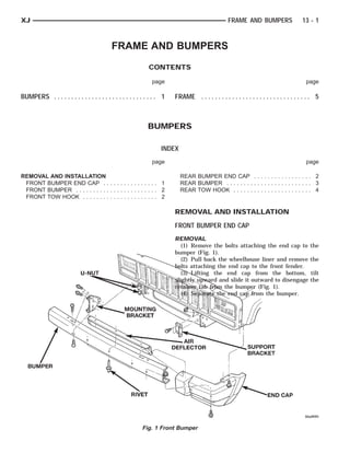
1. BUMPER U-NUT
MOUNTING BRACKET RIVET AIR DEFLECTOR SUPPORT BRACKET END CAP
XJ FRAME AND BUMPERS 13 - 1
FRAME AND BUMPERS
CONTENTS
page page
BUMPERS . . . . . . . . . . . . . . . . . . . . . . . . . . . . . . 1 FRAME . . . . . . . . . . . . . . . . . . . . . . . . . . . . . . . . 5
BUMPERS
INDEX
page page
REMOVAL AND INSTALLATION REAR BUMPER END CAP . . . . . . . . . . . . . . . . . 2
FRONT BUMPER END CAP . . . . . . . . . . . . . . . . 1 REAR BUMPER . . . . . . . . . . . . . . . . . . . . . . . . . 3
FRONT BUMPER . . . . . . . . . . . . . . . . . . . . . . . . 2 REAR TOW HOOK . . . . . . . . . . . . . . . . . . . . . . . 4
FRONT TOW HOOK . . . . . . . . . . . . . . . . . . . . . . 2
REMOVAL AND INSTALLATION
FRONT BUMPER END CAP
REMOVAL
(1) Remove the bolts attaching the end cap to the
bumper (Fig. 1).
(2) Pull back the wheelhouse liner and remove the
bolts attaching the end cap to the front fender.
(3) Lifting the end cap from the bottom, tilt
slightly upward and slide it outward to disengage the
retainer tab from the bumper (Fig. 1).
(4) Separate the end cap from the bumper.
Fig. 1 Front Bumper
2. BUMPER
GRILLE BUMPER END CAP
RETAINER TAB VACUUM RESER-
VOIR VACUUM LINE RESERVOIR SCREWS
13 - 2 FRAME AND BUMPERS XJ
REMOVAL AND INSTALLATION (Continued)
Fig. 2 Bumper End Cap
INSTALLATION
(1) position the end cap on the bumper and engage TOW TOW HOOK
HOOK REINFORCE-
MENT MOUNTING BRACKET
the retaining tab. Fig. 3 Vacuum Reservoir
(2) Install the bolts attaching the end cap to the (2) Separate tow hook from reinforcement.
front fender. (3) If necessary, remove bolt attaching tow hook
(3) Install the bolts attaching the end cap to the reinforcement to frame.
bumper. Tighten the nut to 9 N·m (7 ft. lbs.) torque.
FRONT BUMPER
REMOVAL
(1) Remove bumper end caps.
(2) If equipped, disengage fog lamp wire harness
connectors.
(3) Disconnect vacuum line from reservoir (Fig. 3).
(4) Remove Torx-head bolts that attach bumper to
mounting brackets (Fig. 1).
(5) Remove bumper from vehicle.
(6) If necessary, remove bolts attaching bumper
mounting brackets to frame.
INSTALLATION
(1) If removed, install bolts attaching bumper
mounting brackets to frame. Tighten bolts to 55 N·m Fig. 4 Front Tow Hook
(41 ft. lbs.) torque. INSTALLATION
(2) Position bumper on front of vehicle. (1) If removed, install bolt attaching tow hook
(3) Install Torx-head bolts that attach bumper to reinforcement to frame. Tighten nut to 30 N·m (22 ft.
mounting brackets. Tighten bolts to 55 N·m (41 ft. lbs.) torque.
lbs.) torque. (2) Position tow hook on reinforcement.
(4) Connect vacuum line to reservoir. (3) Install bolts attaching tow hook to tow hook
(5) If equipped, engage fog lamp wire harness con- reinforcement. Tighten nuts to 100 N·m (74 ft. lbs.)
nectors. torque.
(6) Install bumper end caps.
REAR BUMPER END CAP
FRONT TOW HOOK
REMOVAL
REMOVAL (1) Remove the bolt attaching the underside of the
(1) Remove bolts attaching tow hook to tow hook end cap to the bumper (Fig. 5).
reinforcement (Fig. 4).
3. BUMPER SPLASHRIVET
PLASTIC BLIND
SHIELD U-NUTU-NUT
REAR SILL BRACKET UPPER REINFORCEMENT
U-NUT END CAP LOWERFORCEMENT
REIN- RETAINER RIVET
XJ FRAME AND BUMPERS 13 - 3
REMOVAL AND INSTALLATION (Continued)
(2) Remove the screw attaching the front of the (2) Remove bumper end caps.
end cap to the underside of the quarter panel. (3) Remove bolts that attach bumper to bumper
(3) Lift the end cap slightly upward and slide it support brackets (Fig. 5).
rearward to release it from the retainer. (4) Remove bumper from vehicle.
(4) Separate the end cap from the vehicle. (5) If necessary, remove bumper support brackets
from the rear sill.
INSTALLATION
(1) Position the end cap on the rear of the retainer INSTALLATION
and the outer edge of the bumper. (1) If removed, install bumper support brackets on
(2) Slide the end cap forward onto the retainer. the rear sill. Tighten bolts to 55 N·m (41 ft. lbs.)
Ensure the end cap overlaps the lip of the rear torque.
wheelhouse liner. (2) Position bumper on support brackets.
(3) Install the screw attaching the front of the end (3) Install bolts that attach bumper to bumper
cap to the underside of the quarter panel. support brackets. Tighten bolts to 55 N·m (41 ft. lbs.)
(4) Install the bolt attaching the underside of the torque.
end cap to the bumper. (4) Install bumper end caps.
(5) If removed, install trailer hitch.
REAR BUMPER
REMOVAL
(1) For vehicles equipped with a trailer hitch,
remove hitch before removing bumper. If necessary,
refer to removal procedure within Group 13, Frame
and Bumpers.
Fig. 5 Rear Bumper
4. FRAME RAIL
BOLT FWD BOLT TOWHOOK BOLT SUPPORT BRACKET
NUT FORCEMENTREIN-
FRAME
BRACKET RIVET
13 - 4 FRAME AND BUMPERS XJ
REMOVAL AND INSTALLATION (Continued)
REAR TOW HOOK
REMOVAL
(1) Remove bolts that attach tow hook bracket and
tow hook to frame rail (Fig. 6).
(2) Remove bracket and tow hook from frame rail.
INSTALLATION
(1) Position bracket and tow hook on frame rail.
(2) Install bolts that attach tow hook bracket and
tow hook to frame rail. Tighten bolts to 94 N·m (70
ft. lbs.) torque.
Fig. 6 Rear Tow Hook
5. SCREW
PUSH NUT NUT STUD SCREW FWD
SPLASHSHIELD
SKID PLATE CROSSMEMBER
SKID PLATE
NUT-SERT
FWD BOLT FRAME SILL CASE
NUT-SERT
TRANSFER
XJ FRAME AND BUMPERS 13 - 5
FRAME
INDEX
page page
REMOVAL AND INSTALLATION TRANSFER CASE SKID PLATE . . . . . . . . . . . . . 5
FRONT SKID PLATE . . . . . . . . . . . . . . . . . . . . . 5 SPECIFICATIONS
FUEL TANK SKID PLATE . . . . . . . . . . . . . . . . . . 5 FRAME TORQUE SPECIFICATIONS . . . . . . . . 16
TRAILER HITCH . . . . . . . . . . . . . . . . . . . . . . . . 6 VEHICLE DIMENSIONS . . . . . . . . . . . . . . . . . . . 7
REMOVAL AND INSTALLATION TRANSFER CASE SKID PLATE
FRONT SKID PLATE REMOVAL
(1) Support skid plate.
REMOVAL (2) Remove bolts that attach skid plate to trans-
(1) Remove the screws that attach skid plate to mission support crossmember and frame sill (Fig. 2).
side sills. (3) Remove support and skid plate from vehicle.
(2) Remove the nuts that attach the skid plate to
the crossmember (Fig. 1).
(3) Remove the skid plate from the vehicle.
Fig. 2 Transfer Case Skid Plate
INSTALLATION
(1) Position and support skid plate at frame sill
and transmission support crossmember.
(2) Attach skid plate to frame sill and crossmem-
ber with bolts. Tighten bolts to 260 N·m (192 ft. lbs.)
torque.
FUEL TANK SKID PLATE
Fig. 1 Front Skid Plate
INSTALLATION REMOVAL
(1) Position the skid plate at front crossmember (1) Position a support under skid plate.
and side sills. (2) Remove bolts that attach skid plate to under-
(2) Install the nuts to attach the skid plate to body side rails (Fig. 3).
crossmember. (3) Remove support and skid plate from vehicle.
(3) Install the screws to attach skid plate to side
INSTALLATION
sills.
(1) Position and support skid plate under fuel
tank.
6. FUEL BLIND PLATE
TANK RIVET
SKID RIVET HOLES REINFORCEMENT
13 - 6 FRAME AND BUMPERS XJ
REMOVAL AND INSTALLATION (Continued)
TRAILER HITCH
BLIND RIVET RIVET HOLES REINFORCEMENT
Fig. 3 Fuel Tank Skid Plate Fig. 4 Trailer Hitch Harness Connector
(2) Install bolts to attach skid plate to underbody
rails. Tighten bolts to 74 N·m (55 ft. lbs.) torque.
(3) Remove support from under skid plate.
TRAILER HITCH
REMOVAL
(1) If necessary, remove the trailer tow wire har-
ness connector from the hitch (Fig. 4).
(2) Support the hitch.
(3) Remove the bolts that attach the trailer hitch
to the frame sills and reinforcement brackets (Fig. 5).
(4) If equipped, remove the fuel tank skid plate.
NOTE: The reinforcement brackets are held on the
frame sills with two blind rivets.
Fig. 5 Trailer Hitch
INSTALLATION (4) Loosely install the bolts to attach the trailer
(1) Install frame reinforcement brackets, if hitch (and the skid plate) to frame sills and reinforce-
removed. Slide the brackets through the vehicle rear ment brackets.
sill openings and attach to the frame sills with blind (5) Tighten all bolts/nuts to 74 N·m (55 ft. lbs.)
rivets. torque.
(2) Using an adequate lifting device, position hitch (6) Remove the lift/support.
at the proper location for installation on vehicle and (7) If removed, attach the trailer wire harness con-
support it. nector to the hitch.
(3) If equipped, position fuel tank skid plate on
vehicle frame sills.
7. XJ FRAME AND BUMPERS 13 - 7
SPECIFICATIONS
VEHICLE DIMENSIONS
WINDSHIELD OPENING
• A. & B. Center of radius at bottom to center of
radius at tp
8. 13 - 8 FRAME AND BUMPERS XJ
SPECIFICATIONS (Continued)
FRONT DOOR OPENING 2–DOOR
• A. Center of front door lower rear radius to cen-
ter of A-pillar radius
• B. Center of radius at bottom rear to center of
radius at lower A-pillar
• C. Center of radius at bottom front to center of
radius at top rear
9. XJ FRAME AND BUMPERS 13 - 9
SPECIFICATIONS (Continued)
FRONT DOOR OPENING 4–DOOR
• C. Center of front door lower rear radius to cen-
ter of A-pillar radius
• E. Center of radius at bottom rear to center of
radius at lower A-pillar
• F. Center of radius at bottom front to center of
radius at top rear
10. 13 - 10 FRAME AND BUMPERS XJ
SPECIFICATIONS (Continued)
REAR DOOR OPENING
• A. Quarter panel to front outer body side upper
and lower seam
• B. Center of front upper door radius to center of
rear lower door radius
• C. Center of front lower door radius to center of
rear upper door radius
• D. Rear door hinge mount to rear door striker
mount
11. XJ FRAME AND BUMPERS 13 - 11
SPECIFICATIONS (Continued)
QUARTER WINDOW OPENING 2–DOOR
• A. Center of upper and lower rear quarter win-
dow opening
• B. Center of radius front lower corner to center
of radius rear upper corner
• C. Center of radius front upper corner to center
of radius rear lower corner
12. 13 - 12 FRAME AND BUMPERS XJ
SPECIFICATIONS (Continued)
QUARTER WINDOW OPENING 4–DOOR
• A. Center of upper and lower rear quarter win-
dow opening
• B. Center of radius front lower corner to center
of radius rear upper corner
• C. Center of radius front upper corner to center
of radius rear lower corner
14. 13 - 14 FRAME AND BUMPERS XJ
SPECIFICATIONS (Continued)
LIFTGATE OPENING
• A. Center of upper liftgate opening to liftgate
striker mount
• B. & C. Center of radius upper corner to center
of radius lower corner
• D. Distance between outer quarter panel to tail
lamp mounting panel to inner quarter panel seams
FRAME DIMENSIONS
Frame dimensions are listed in millimeter scale.
All dimensions are from center to center of Principal
Locating Point (PLP), or from center to center of PLP
and fastener location (Fig. 6).
16. 13 - 16 FRAME AND BUMPERS XJ
SPECIFICATIONS (Continued)
FRAME TORQUE SPECIFICATIONS
DESCRIPTION TORQUE
Front Skid Plate Screw . . . . . . . . 42 N·m (31 ft. lbs.)
Front Skid Plate Nut . . . . . . . . 17 N·m (150 in. lbs.)
Transfer Case Skid
Plate Bolt . . . . . . . . . . . . . . 260 N·m (192 ft. lbs.)
Fuel Tank Skid Plate Bolt . . . . . 74 N·m (55 ft. lbs.)
Front Bumper End Cap to
Mounting Bracket Nut . . . . . . . . 9 N·m (7 ft. lbs.)
Front Bumper Mounting Bracket to
Frame Bolt . . . . . . . . . . . . . . . 55 N·m (41 ft. lbs.)
Front Bumper to Mounting Bracket
Bolt . . . . . . . . . . . . . . . . . . . . . 55 N·m (41 ft. lbs.)
Front Tow Hook Nut . . . . . . . . . 100 N·m (74 ft. lbs.)
Front Tow Hook
Reinforcement Nut . . . . . . . . . 30 N·m (22 ft. lbs.)
Rear Bumper to Mtg.
Bracket Bolt . . . . . . . . . . . . . . 55N·m (41 ft. lbs.)
Rear Bumper Mtg. Bracket to
Rear Sill Bolt . . . . . . . . . . . . . 55 N·m (41 ft. lbs.)
Rear Tow Hook Bolt . . . . . . . . . . 94 N·m (70 ft. lbs.)
Trailer Tow Reinforcement Brkt
Bolt . . . . . . . . . . . . . . . . . . . . . 74 N·m (55 ft. lbs.)
Trailer Tow Plate Bracket Nut . . 52 N·m (40 ft. lbs.)
17. XJ FRAME AND BUMPERS 13 - 1
FRAME AND BUMPERS
CONTENTS
page
FRAME . . . . . . . . . . . . . . . . . . . . . . . . . . . . . . . . 1
FRAME
INDEX
page
GENERAL INFORMATION
EMERGENCY TOW EYES . . . . . . . . . . . . . . . . . 1
GENERAL INFORMATION
EMERGENCY TOW EYES
If your vehicle is equipped with emergency tow
eyes, one is mounted in the front and one in the rear.
The front tow eye has two holes, the front hole is
for towing use only and the rear angled hole is for
shipping use only.
CAUTION: Do not use the angled hole for towing.
You could damage your vehicle.
WARNING: Stand clear of vehicles when pulling
with tow eyes. Tow straps and chains may break,
causing serious injury.
CAUTION: Tow eyes are for emergency use only, to
rescue a vehicle stranded off road. Do not use tow
eyes for tow truck hookup or highway towing. You
could damage your vehicle.
Fig. 1 Emergency Tow Eyes