Downloaded 112 times


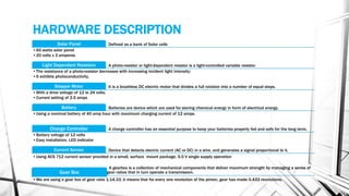


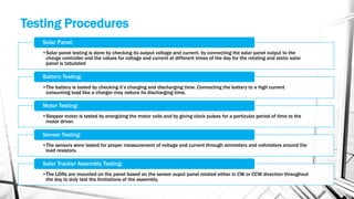

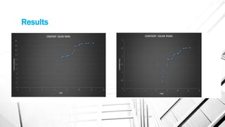


The document discusses a project aimed at maximizing solar energy absorption using a dual-axis solar tracker that adjusts to the sun's position, thereby minimizing energy loss from stationary solar panels. It details the components and design considerations involved, including the use of microcontrollers and various sensors for data logging of voltage and current. The project also evaluates the operational efficiency and applications of the system while addressing the benefits and challenges of implementing solar tracking technology.


