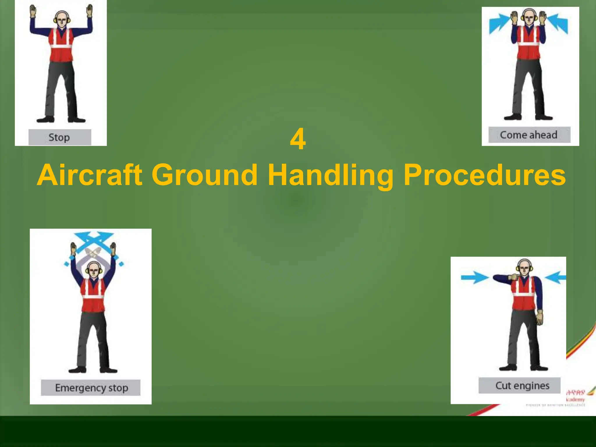
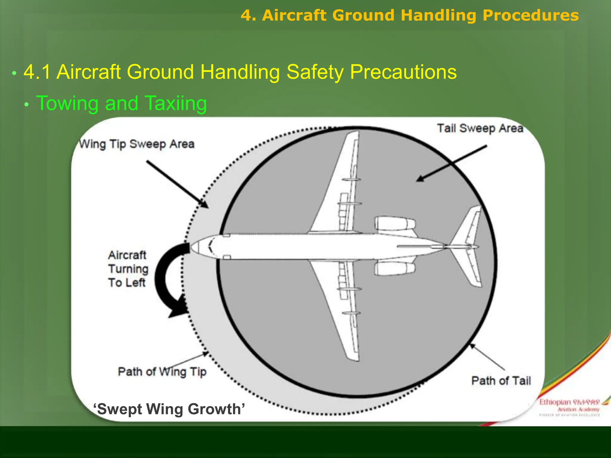
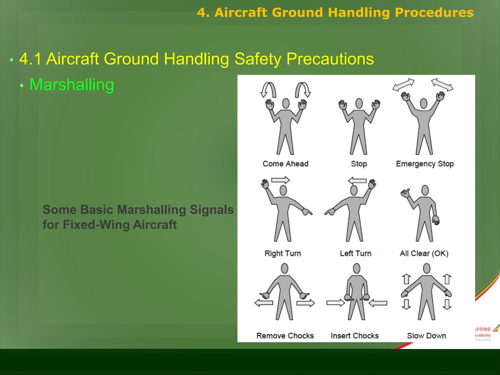
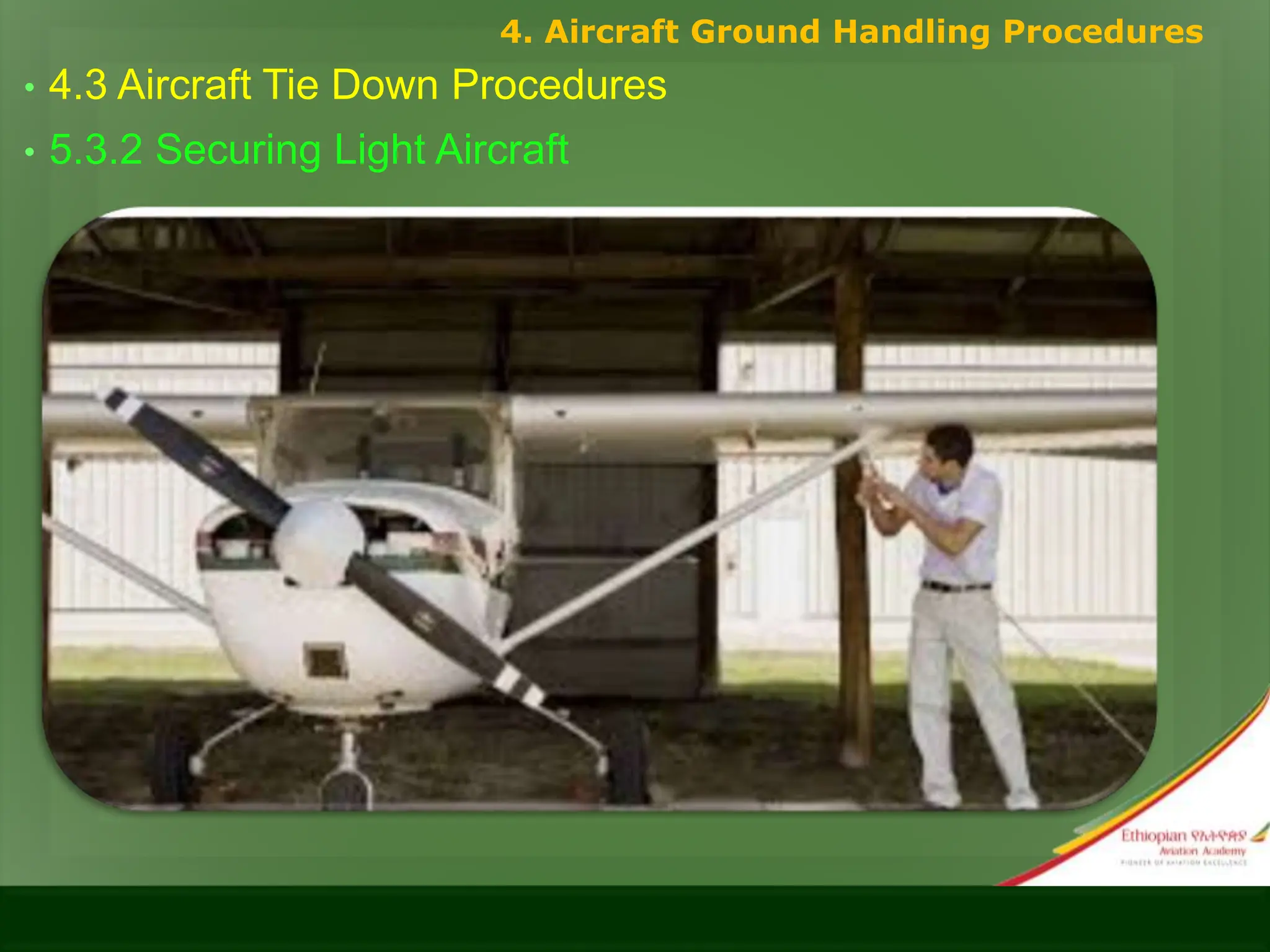
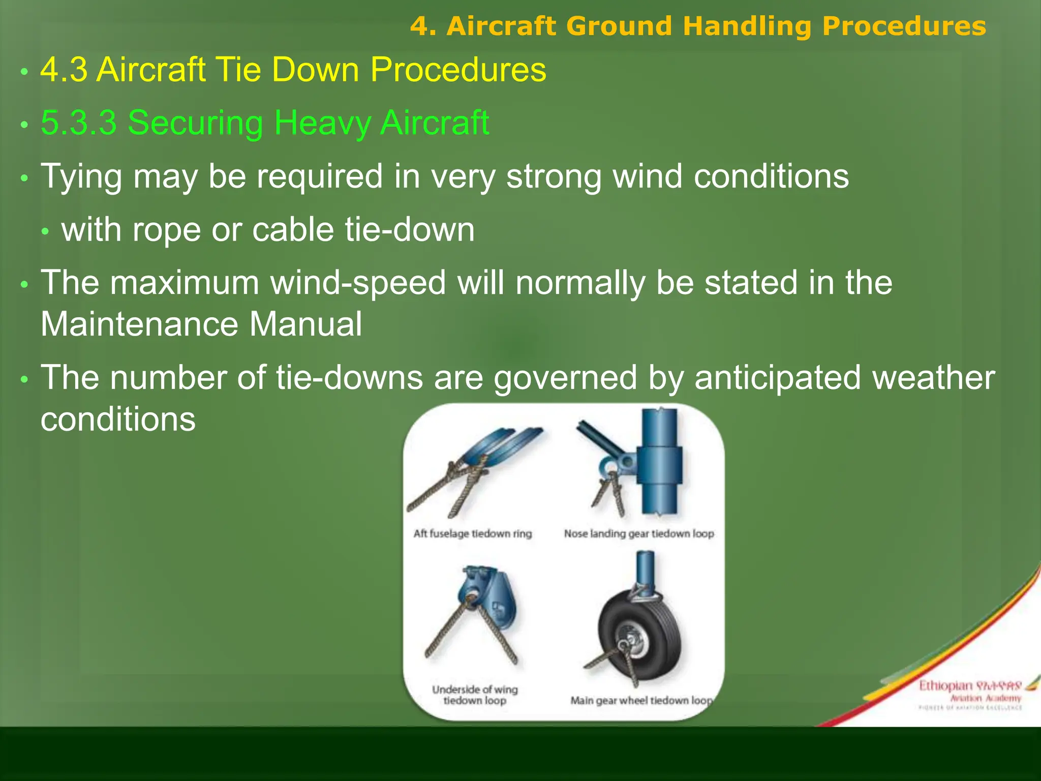
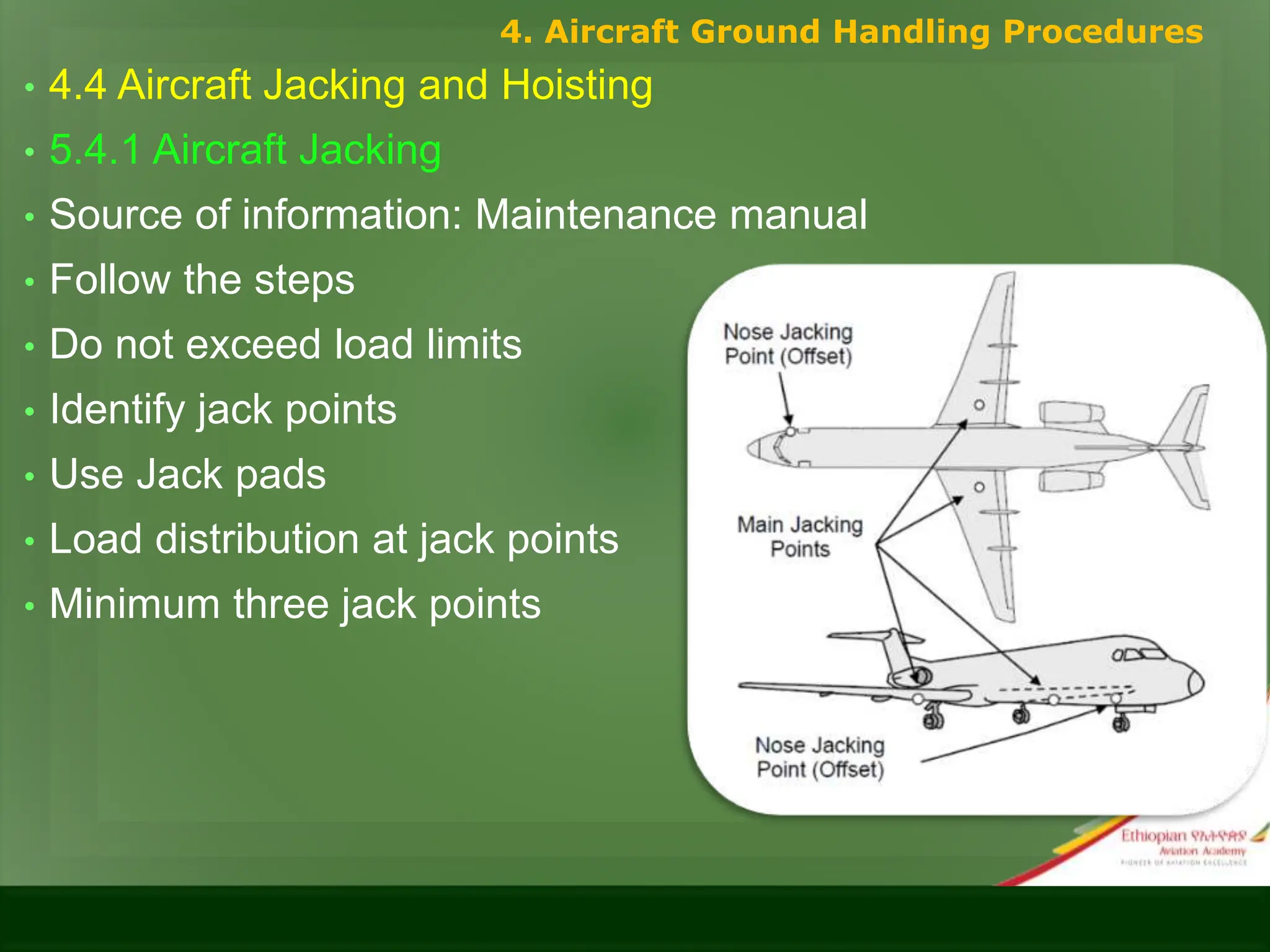
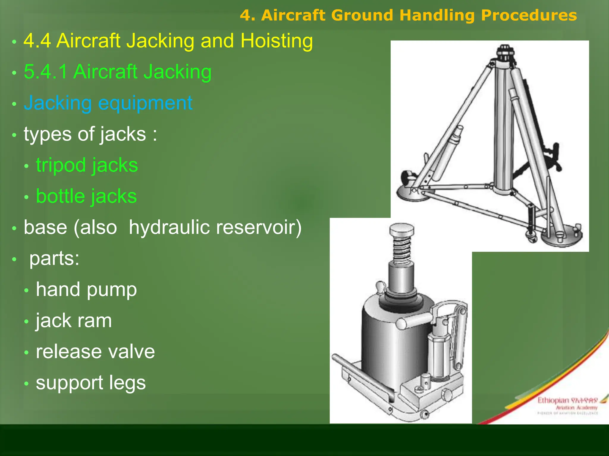
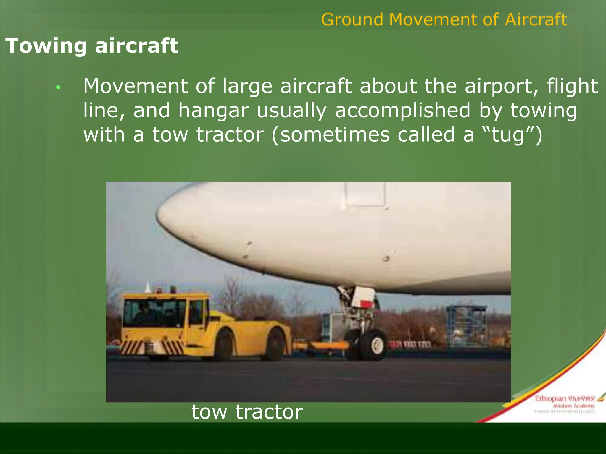
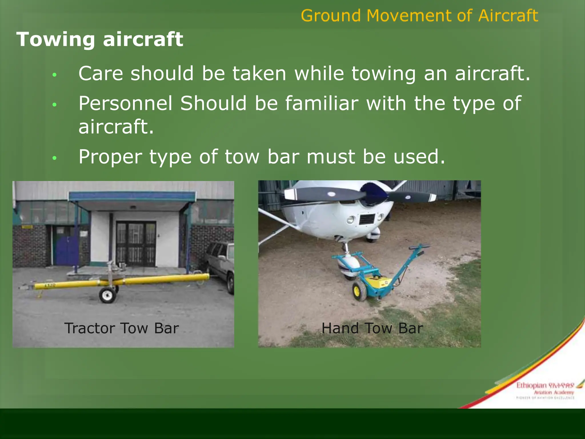
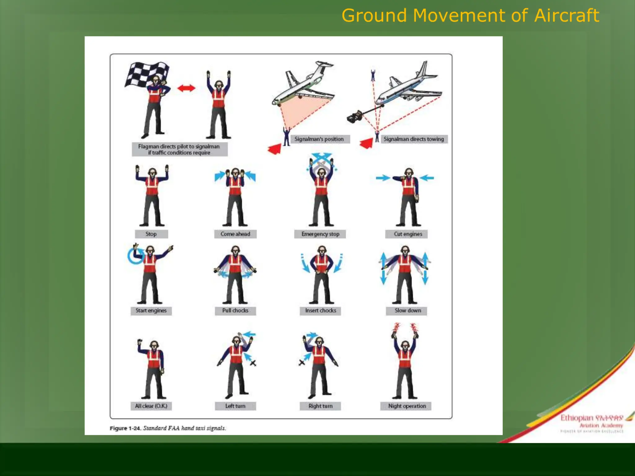
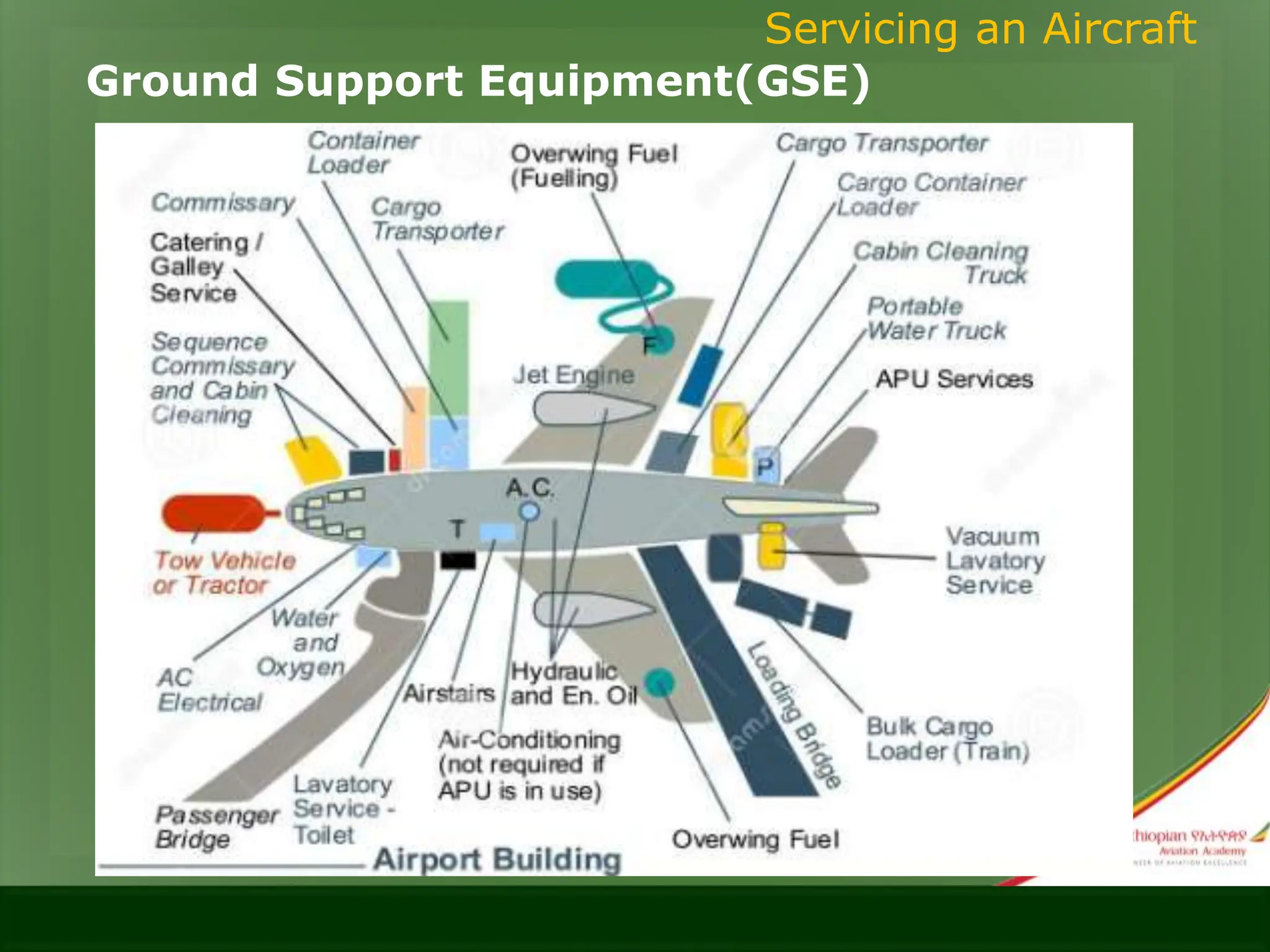
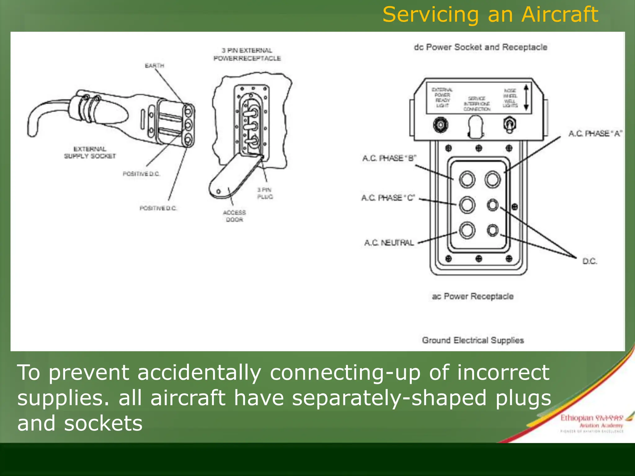
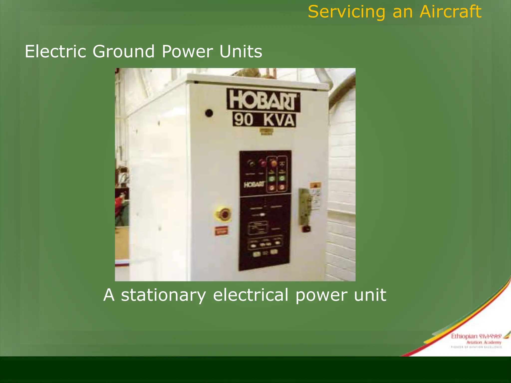
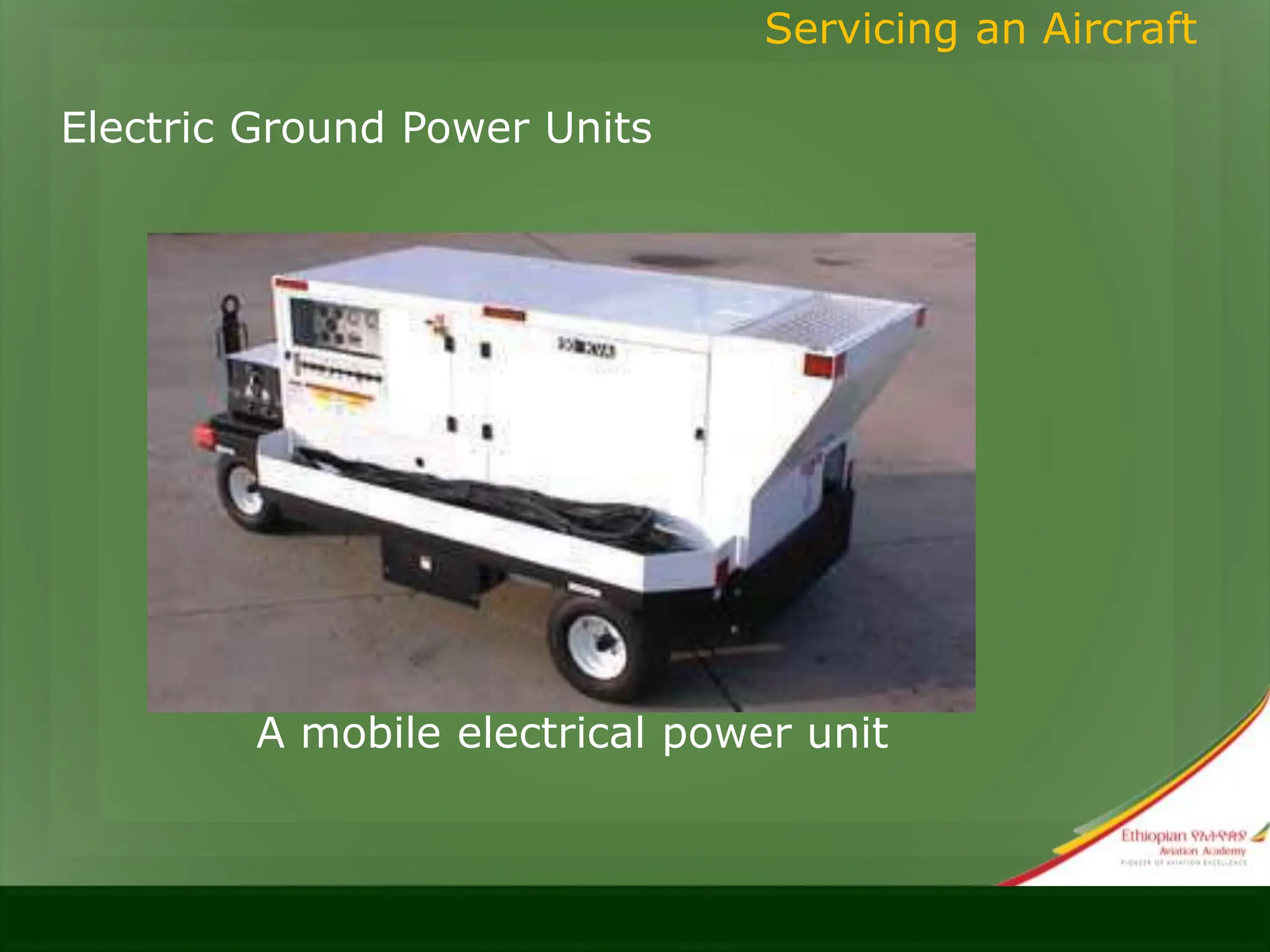
Welcome to
ETHIOPIAN AVIATION ACADEMY
AVIATION MAINTENANCE
TRAINING
1
ET-AF08
Aircraft Inspection, Documentation and
Ground Handling
2
COURSE OBJECTIVE
• Trainees will be able to :
• Define a/c inspection and state its objectives
• Describe required insp. on certificated aircraft
• Describe insp. procedures and methods
• Describe a/c non-destructive insp. methods
• Define maintenance records and entries
• Describe a/c maintenance publications
• Identify aircraft handling procedures
• Describe aircraft handling safety precautions
4
Aircraft Ground Handling Procedures
• 4.1 Aircraft Ground Handling Safety Precautions
• Flight-Line Safety
• Accidents from propellers and rotor blades
• difficult to see when turning
• Cause fatal accidents
• blades high-visibility markings:
• vary from a yellow blade tip marking, to black and white
alternate stripes along the full blade length.
• Follow the correct way to approach and leave the vicinity of an
aircraft or helicopter whilst it is under power
4. Aircraft Ground Handling Procedures
• 4.1 Aircraft Ground Handling Safety Precautions
• Towing and Taxiing
• For towing use a tug and towing arm
• requires a qualified tug driver, a supervisor, a ‘brakeman’ and
other personnel to keep a lookout
• rules to be laid down:
• number of people needed
• the type of tug
• the radio calls if the aircraft is on the maneuvering area
• the maximum towing speed etc
4. Aircraft Ground Handling Procedures
• 4.1 Aircraft Ground Handling Safety Precautions
• Towing and Taxiing
4. Aircraft Ground Handling Procedures
‘Swept Wing Growth’
• 4.1 Aircraft Ground Handling Safety Precautions
• Parking
• precautions to be observed(as required):
• Put chocks at the front and rear wheels
• Cover engine intakes and exhausts with special blanks
• Lock the control surfaces in place
• Cover pitot tubes and static vents
4. Aircraft Ground Handling Procedures
• 4.1 Aircraft Ground Handling Safety Precautions
• Marshalling
• Require full knowledge of marshalling signals
• The need for additional, ‘lookout’ men on the wing tips or tail
• The correct place to stand to enable the aircraft’s crew to have
sight of the marshaller
• The point at which the aircraft is required to stop
4. Aircraft Ground Handling Procedures
• 4.1 Aircraft Ground Handling Safety Precautions
• Marshalling
4. Aircraft Ground Handling Procedures
Some Basic Marshalling Signals
for Fixed-Wing Aircraft
• 4.1 Aircraft Ground Handling Safety Precautions
• Fueling
• covered in ATA 28
• Precaution:
• identification of fuel type and grade
• stenciled or painted, adjacent to the fueling point
• Park the fuel tanker as far as possible from and parallel to the
aircraft
• Electrically bond the fuel tanker, the fueling hose, the aircraft
and the ground
4. Aircraft Ground Handling Procedures
• 4.1 Aircraft Ground Handling Safety Precautions
• Fueling
• Establish a safe zone
• Switch off radio and radar equipment
4. Aircraft Ground Handling Procedures
• 4.1 Aircraft Ground Handling Safety Precautions
• Weather Radar
• Has heating and radiation effects
• Keep a safe distance from the radar if it is in operation.
• Refer to AMM
4. Aircraft Ground Handling Procedures
• 4.2 Aircraft Safety Equipment
• 4.2.1 Ground Locks & Wheel Chocks
• Ground Locks
• external devices placed in the retraction mechanism
• simple pin
• Clamp
• keeps landing gear down and locked
• have red streamers attached to them
4. Aircraft Ground Handling Procedures
• 4.2 Aircraft Safety Equipment
• 4.2.1 Ground Locks & Wheel Chocks
• Ground Locks
4. Aircraft Ground Handling Procedures
• 4.2 Aircraft Safety Equipment
• 4.2.1 Ground Locks & Wheel Chocks
• Wheel Chocks
• Placed fore and aft of the wheels to prevent a/c movement
• Put parking brakes to Off position once chocks are placed for
brake heat dissipation
• At high wind speeds, chock all the wheels and apply the
brakes (if they have cooled)
• Chocks chained together give a more secure hold
• place chocks at the front of main wheels sets during
ground runs to reinforce the parking brake.
4. Aircraft Ground Handling Procedures
• 4.2 Aircraft Safety Equipment
• 4.2.1 Ground Locks & Wheel Chocks
• Wheel Chocks
4. Aircraft Ground Handling Procedures
• 4.2 Aircraft Safety Equipment
• 4.2.2 Covers, Support & Safety Devices
• covers are used to protect aircraft parts from:
• FOD (Foreign Object Damages)
• Chemical Aggressions
• Outdoor weather : Corrosion due to humidity, weather
(snow, rain, cold)
• Damages : Scratches, Bumps
4. Aircraft Ground Handling Procedures
• 4.2 Aircraft Safety Equipment
• 4.2.2 Covers, Support & Safety Devices
• Protects:
• Engines
• air-conditioning system intakes
• pitot and static system openings etc.
4. Aircraft Ground Handling Procedures
• 4.2 Aircraft Safety Equipment
• 4.2.2 Covers, Support & Safety Devices
4. Aircraft Ground Handling Procedures
• 4.2 Aircraft Safety Equipment
• 4.2.3 Tie-Down Devices
• Ropes: to secure light aircraft
• Cable or chain: to secure large aircraft
• Components of tiedown assembly :
• metal quick- release mechanism
• a tensioning device
• a length of chain with hooks
4. Aircraft Ground Handling Procedures
• 4.3 Aircraft Tie Down Procedures
• 5.3.1 Purpose of Aircraft Tie-Down
• Mooring (Picketing)
• Certain weather conditions require parking aircraft in hangars
• If they must be left outside, then smaller aircraft may need to be
tied down
• picketing rings or attachment points may be provided at the
wings and tail or adjacent to the undercarriage legs
• the aircraft should always be parked nose into wind
4. Aircraft Ground Handling Procedures
• 4.3 Aircraft Tie Down Procedures
• 5.3.1 Purpose of Aircraft Tie-Down
• Mooring (Picketing)
4. Aircraft Ground Handling Procedures
• 4.3 Aircraft Tie Down Procedures
• 5.3.2 Securing Light Aircraft
• if possible, park the a/c head into the wind
• Secure control surfaces internal control lock and the brakes
applied
Note:
• accumulated moisture may freeze the brakes
• apply control lock to the pilot's control column. Tie back with a
front seat bet
• secure with ropes tied only at the aircraft tie-down rings provided
for securing purposes
• 1 inch of slack needed to compensate rope shrinkage
4. Aircraft Ground Handling Procedures
• 4.3 Aircraft Tie Down Procedures
• 5.3.2 Securing Light Aircraft
4. Aircraft Ground Handling Procedures
• 4.3 Aircraft Tie Down Procedures
• 5.3.3 Securing Heavy Aircraft
• Tying may be required in very strong wind conditions
• with rope or cable tie-down
• The maximum wind-speed will normally be stated in the
Maintenance Manual
• The number of tie-downs are governed by anticipated weather
conditions
4. Aircraft Ground Handling Procedures
• 4.4 Aircraft Jacking and Hoisting
• 5.4.1 Aircraft Jacking
• Source of information: Maintenance manual
• Follow the steps
• Do not exceed load limits
• Identify jack points
• Use Jack pads
• Load distribution at jack points
• Minimum three jack points
4. Aircraft Ground Handling Procedures
• 4.4 Aircraft Jacking and Hoisting
• 5.4.1 Aircraft Jacking
• Jacking equipment
• types of jacks :
• tripod jacks
• bottle jacks
• base (also hydraulic reservoir)
• parts:
• hand pump
• jack ram
• release valve
• support legs
4. Aircraft Ground Handling Procedures
Jack pads
• Permanent
• removable
• Function:
• ensure proper aircraft load distribution at the jack
point
Jack pads
Jacking points
• Refer maintenance manual for jack points
• usually located in relation to the aircraft CG for
proper balance
Jacking -precautions
• Avoid personal and property damage
• inspect jack before use
• Check specific lifting capacity, proper functioning of
safety locks, condition of pins,
and general serviceability.
• Remove stands and equipment
• No one should remain in the aircraft while it is
being raised or lowered, unless maintenance
manual procedures require such practice for
observing leveling instruments in the aircraft.
Jacking Complete Aircraft
• At least three places or points are provided on
aircraft for jacking purposes
• a fourth place on some aircraft is used to stabilize
the aircraft while it is being jacked at the other
three points
• The two main places are on the wings, with a
smaller one on the fuselage near either the tail or
the nose, depending on the landing gear design.
Jacking Complete Aircraft
Jacking One Wheel of an Aircraft
• For tire change and grease wheel bearings
• Use a low single base jack is used
• Before raising the wheel, chock the remaining
wheels to prevent movement
Hoisting
• Do not exceed load limit
• Identify hoisting points
Trestling Aircraft:
• Trestling stabilizes the aircraft because the aircraft
weight is spread over a larger fixed area.
4.5. Ground Movement of Aircraft
Flight line Safety
• propellers or rotors are sources of accidents
• Safety habits
• Treat all propellers as though the ignition switches
are on.
• Chock airplane wheels before working on aircraft.
• Attach pull ropes to pull chokes
• Always stand clear off propeller and rotor blade
paths
Engine Starting and Operation
Before starting an aircraft engine:
• Position the aircraft to head into the prevailing wind
• Station a “fire guard”
• Clear engine inlet and exhaust area
• Ensure external electrical power safe removal and its
sufficiency for total starting sequence
• Follow manufacturer’s checklists for start procedures
and shutdown procedures.
Engine Starting and Operation
Reciprocating Engines
• always refer to the procedures contained in the
applicable manufacturer’s instructions
• Use external sources of electrical power when starting
engines if possible or needed
• eliminates an excessive burden on the aircraft
battery
• If engine is shut down for more than 30 minutes:
• check the ignition switch for off
• Turn the propeller 3 or 4 complete revolutions by
hand to detect a hydraulic lock, if one is present
• Follow the manufactures instruction to start the
engine
Ground Movement of Aircraft
Reciprocating Engines
• Hand Cranking Engines
• Starting engine by turning the propeller by hand
(hand propping the propeller)
• For aircrafts with no self-starter
• Two persons needed
• The person who is turning the propeller calls: “Fuel
on, switch off, throttle closed, brakes on.” The
person operating the engine checks these items and
repeats the phrase. The switch and throttle must
not be touched again until the person swinging the
prop calls “contact.” The operator repeats “contact”
and then turns on the switch. Never turn on the
switch and then call “contact.”
Ground Movement of Aircraft
Starting turboprop engines
• Pre-start procedures
• Remove protective covers
• Inspect tailpipes carefully
• Inspect all accessible areas and engine controls
• Inspect the nacelle area to ensure that all access
plates are secured
• Check sumps for water
• Check air inlet areas
• Check compressor for free rotation
Ground Movement of Aircraft
Starting turboprop engines
• Typical on ground starting procedure:
• Turn the aircraft boost pumps on
• Put power lever in the “start” position
• Place the start switch in the “start” position
• Place the ignition switch on
• The fuel is now turned on
• Monitor the engine lights of the exhaust temperature
• If it exceeds the limits, shut the engine down.
Starting turboprop engines
• Check the oil pressure and temperature.
• After the engine reaches a self-sustaining speed, the
• starter is disengaged.
• The engine continues to accelerate up to idle.
• Maintain the power lever at the “start” position until
• the specified minimum oil temperature is reached.
• Disconnect the ground power supply, if used.
Starting a Turbofan Engine
• place the power lever in the “idle” position
• Turn the fuel boost pump(s) switch on.
• Turn engine starter switch on
• Turn ignition switch on
• Move the start lever to “idle” or “start” position
• Turn engine starter switch off at proper speeds.
• After engine stabilizes at idle, ensure that none of
the engine limits are exceeded.
Engine intake and
exhaust hazard areas
Auxiliary Power Units (APUs)
• Small turbine engines that provide compressed air
for:
• starting engines
• cabin heating and cooling
• electrical power while on the ground
Auxiliary Power Units (APUs)
• Operation:
• turn a switch on and up to the start position, the
engine starts automatically
• Monitor exhaust gas temperature during start
Taxiing aircraft
• A controlled movement of the airplane under its own
power while on ground
• Performed by rated pilots and technicians Only
• Radio must be tuned to ground control
frequency
• If radio is not available taxi lights can be used
Standard taxi light signals.
• Stay in the pilot’s field of vision
• If the signalman can see the pilot’s eyes, the pilot
can see the signals.
Towing aircraft
• Movement of large aircraft about the airport, flight
line, and hangar usually accomplished by towing
with a tow tractor (sometimes called a “tug”)
tow tractor
Towing aircraft
• Care should be taken while towing an aircraft.
• Personnel Should be familiar with the type of
aircraft.
• Proper type of tow bar must be used.
Tractor Tow Bar Hand Tow Bar
Towing Precaution
• Driver responsible for vehicle safe operation
• wing walkers ensure adequate clearance
• A tail walker for sharp or backing aircraft into
position.
• A qualified person on pilot’s seat to observe and
operate the brakes
• Charged brake system & brake operation
• Chocks
• Tire inflation
• Communication
Aircraft marshalling
• visual communication between ground personnel
and pilots
• mainly done using visual communication through
body signals.
• Pilots have limited vision both of the aircraft and of
ground obstacles from the cockpit
• The marshaller, thus, guides the pilot to the
parking position in a safe manner
• Also used for preparing the aircraft for departure
Aircraft marshalling is
4.6. Servicing an Aircraft
Servicing Aircraft Air/Nitrogen Oil and Fluids
• consult the specific aircraft maintenance manual to
determine
• the proper type of servicing equipment
• procedures
• Use the following to check for engine oil
• a dipstick
• a sight gauge
When to check?
• For reciprocating engines: after the engine has
been inactive
• turbine engine: just after shutdown
servicing hydraulic reservoir
• use correct fluid type
• can be determined by the container
• or by color
• Bleed off pressurized reservoirs before servicing
• Prevent any type of contamination
• To change hydraulic filters
• assure that the pressure is off the system
• After servicing
• Purge out air
• check for leak.
Servicing an Aircraft
Ground Support Equipment(GSE)
• Provide support for the operation of the aircraft
while the aircraft is on ground
• Functions:
• Ground power operations
• aircraft mobility
• loading operations
Servicing an Aircraft
Ground Support Equipment(GSE)
Servicing an Aircraft
Ground Support Equipment
Electric Ground Power Units
• Classification of ground support electrical APUs
• Towed
• Stationary
• self-propelled
• Uses:
• in-hangar
• on the flight line
Servicing an Aircraft
Electric Ground Power Units
• Power source:
• Stationary: from the electrical service of the
facility
• Movable GPU:
• onboard engine that turns a generator to
produce power
• a series of batteries
• Ground electrical supplies are normally linked to
either 28 volts dc or 115 volts ac
Servicing an Aircraft
To prevent accidentally connecting-up of incorrect
supplies. all aircraft have separately-shaped plugs
and sockets
Electric Ground Power Units
• Power source:
• Stationary: from the electrical service of the
facility
• Movable GPU:
• onboard engine that turns a generator to
produce power
• a series of batteries
Servicing an Aircraft
Electric Ground Power Units
Servicing an Aircraft
A stationary electrical power unit
Electric Ground Power Units
Servicing an Aircraft
A mobile electrical power unit
Hydraulic Ground Power Units
• Also called a hydraulic mule
• usually electrically-powered
• provide hydraulic pressure to operate the aircraft
systems during maintenance
• Drain the aircraft hydraulic systems
• Filter the aircraft system hydraulic fluid
• Refill the aircraft system with clean fluid
• Check the aircraft hydraulic systems for operation
and leaks
Servicing an Aircraft
A portable hydraulic power unit
Pneumatic Ground Power Units
• low-pressure air carts used to provide air that can be
used for:
• starting the engines
• heating and cooling the aircraft on the ground
• generally consists of a builtin APU
• provides bleed air from its compressor for operating
aircraft systems or starting engines
Servicing an Aircraft
Aircraft air start unit
4.7. Cold Weather Ground Handling (De-
Icing/Anti-Icing)
Definitions
• De-icing is the removal of ice that has already formed
• Anti-icing is the prevention of initial ice formation.
Aircraft Ground De/Anti Icing procedures serve three
purposes:
• removal of any frozen or semi frozen moisture from
critical external surfaces of an aircraft on the ground
prior to flight
• protection of those surfaces from the effects of such
contaminant for the period between treatment and
becoming airborne
• removal of any frozen or semi frozen moisture from
engine intakes and fan blades and protection of
external surfaces from subsequent contamination
prior to takeoff.
• Clear all snow and ice from wings, tail, control
surfaces, engine inlets and other critical areas before
the aircraft can take-off.
Critical Surfaces for De-icing and Anti-icing
• Ice formation on an aircraft on the ground may result
from a number of causes:
• Direct precipitation from rain, snow and frost
• Condensation freezing on external surfaces of
integral tanks following prolonged fright at high
altitude
• After taxing through snow or slush, ice may
accumulate on landing gear. forward facing
surfaces and under-surfaces
• The formation of ice on aircraft structures can
produce many adverse effects, and if allowed to
remain may result in some or all of the following:
• Decreased aerofoil lift
• Increased aerofoil drag
• Increased weight
• Decreased engine thrust
• Freezing of moisture in control hinges
• Freezing of micro-switches that affect systems
such as the landing gear retraction
• Ingestion of ice into the engine.
De-icing and Anti-Icing Methods
• De-icing procedures
• Mechanical
• Chemical
• Mechanical methods use blowers, brushes and
rubber scrapers
• chemical methods utilise de-icing fluids
Anti-icing procedure
• provides protection against the formation of ice, frost
and snow on aircraft surfaces for a short period
known as the 'Holdover Time‘ by applying an anti-
icing fluid.
• There are two ways of aircraft de-icing and anti-
icing:
• One Step Method
• Two Step Method
One Step method
• utilizes hot fluid to de-ice the aircraft
• fluid remains on the aircraft surfaces to give a limited
anti-icing capability
Two Step method
• consists of two separate fluid application procedures
• First step - de-icing
• second step - anti-icing
• must be done within three minutes of starting the
first step
• protects the aircraft surfaces for a holdover
period
Areas which require particular attention
• around probes
• antennas
• pitot-static ports
• control surfaces
• landing gear
• inlets and exhausts
Inspection after De-Icing/Anti-Icing Procedures
• External surfaces, for signs of residual snow or
ice
• control surface gaps and hinges
• All protrusions and vents, for signs of damage
• Control surfaces for full and free movement with
hand or controls
• Landing gear mechanisms, doors, bays and
wheel brakes
• Up-locks and micro-switches for correct
operation
Inspection after De-Icing/Anti-Icing Procedures
• Tires to ensure that they are not frozen to the
ground
• Engine air intakes for ice and snow deposits
• Gas turbine engines for freedom of rotation by
hand
• Shock absorber struts and hydraulic jacks for
leaks caused by contraction of seals and metal
parts
• Tire pressures and shock absorber pressure and
extension
• Following the inspections an entry should be
made in the Tech. Log. indicating that the De-
Icing/Anti-Icing procedure has been completed.
• Measures to be taken when parking aircraft in
extreme cold for any length of time:
• Install all covers to prevent snow and ice
accumulations:
• engines
• air-conditioning system intakes
• pitot and static system openings
• ram air inlets
• If parked in snow or ice conditions
• paint glycol antifreeze compounds around doors
and frequently opened access panels
• park the wheels on planking rather than on ice or
packed snow
• retract flaps and spoilers
• Set movable horizontal stabilizers to approximately
zero
• Drain all water and waste systems or them service
with an antifreeze solution
• leave a window partially open to permit air circulation
Cold Weather Ground Handling (De-
Icing/Anti-Icing)
4.8 Effect of Environment Conditions on Ground
Handling
Actions required to be taken for various weather
conditions:
Cold and Wet:
• Can reduces friction between the aircraft's tyres and
the ramp
• This also applies to all self-propelled vehicles
• all movements on the ramp should be at a slower
speed than normal, with quick access to chocks,
in the event of an emergency.
Wet or flooded ramp condition
• may limit maximum power for engine ground
running
• covered in either the Airfield Operations Manual
or the Ground Handling Procedures Manual
• make ensure that no protective clothing get sucked
into a running engine
• place extra chocks at the wheels of the aircraft to
prevent slippage at the higher power settings.
Effect of Environment Conditions on Ground Handling
Falling rain (and fog):
• demand more care to be taken, due to the reduced
visibility, especially when towing is in progress
• use all normal lights, day or night
• inadvisable to re-fuel aircraft by the 'open line' (over
wing) method
• If a task needs to be completed on the upper surface
of a wet wing, use a 'safety raiser* or 'cherry picker‘
• allow safe access to the upper surfaces a wing
provide safety device, to hook onto
Snow and Ice:
• Many of the precautions, already mentioned, also
apply in conditions of snow and ice
• Aircraft towing and taxing may be restricted until all
standing precipitation cleared
• May require the use of heater units or APU
• Sub zero temperature condition may require draining
the potable water tanks
High Winds
• can cause loose objects to move across the ramp and
strike the aircraft
• During very high wind conditions, the smallest
objects can be lethal, due to the energy they contain
• In certain environments, such as desert climates (or
at airfields near seashores). sand and dust driven by
the wind can enter small crevices causing problems
with aircraft systems and may also block filters
• Where extreme conditions exist such as during a
sand storm, blanket all orifices
High Temperature
Take extra precautions for temperature-sensitive
equipment
The operating temperature electronic equipment must
also be kept below a critical level, to ensure its
continued serviceability.
APU can provide a supply of bleed air to allow the air
conditioning system of the aircraft to operate on the
ground.
If an APU is not available connect external air
conditioning units

ET-A08 - aircraft handling.ppt

  • 1.
    Welcome to ETHIOPIAN AVIATIONACADEMY AVIATION MAINTENANCE TRAINING 1
  • 2.
  • 3.
    COURSE OBJECTIVE • Traineeswill be able to : • Define a/c inspection and state its objectives • Describe required insp. on certificated aircraft • Describe insp. procedures and methods • Describe a/c non-destructive insp. methods • Define maintenance records and entries • Describe a/c maintenance publications • Identify aircraft handling procedures • Describe aircraft handling safety precautions
  • 4.
  • 5.
    • 4.1 AircraftGround Handling Safety Precautions • Flight-Line Safety • Accidents from propellers and rotor blades • difficult to see when turning • Cause fatal accidents • blades high-visibility markings: • vary from a yellow blade tip marking, to black and white alternate stripes along the full blade length. • Follow the correct way to approach and leave the vicinity of an aircraft or helicopter whilst it is under power 4. Aircraft Ground Handling Procedures
  • 6.
    • 4.1 AircraftGround Handling Safety Precautions • Towing and Taxiing • For towing use a tug and towing arm • requires a qualified tug driver, a supervisor, a ‘brakeman’ and other personnel to keep a lookout • rules to be laid down: • number of people needed • the type of tug • the radio calls if the aircraft is on the maneuvering area • the maximum towing speed etc 4. Aircraft Ground Handling Procedures
  • 7.
    • 4.1 AircraftGround Handling Safety Precautions • Towing and Taxiing 4. Aircraft Ground Handling Procedures ‘Swept Wing Growth’
  • 8.
    • 4.1 AircraftGround Handling Safety Precautions • Parking • precautions to be observed(as required): • Put chocks at the front and rear wheels • Cover engine intakes and exhausts with special blanks • Lock the control surfaces in place • Cover pitot tubes and static vents 4. Aircraft Ground Handling Procedures
  • 9.
    • 4.1 AircraftGround Handling Safety Precautions • Marshalling • Require full knowledge of marshalling signals • The need for additional, ‘lookout’ men on the wing tips or tail • The correct place to stand to enable the aircraft’s crew to have sight of the marshaller • The point at which the aircraft is required to stop 4. Aircraft Ground Handling Procedures
  • 10.
    • 4.1 AircraftGround Handling Safety Precautions • Marshalling 4. Aircraft Ground Handling Procedures Some Basic Marshalling Signals for Fixed-Wing Aircraft
  • 11.
    • 4.1 AircraftGround Handling Safety Precautions • Fueling • covered in ATA 28 • Precaution: • identification of fuel type and grade • stenciled or painted, adjacent to the fueling point • Park the fuel tanker as far as possible from and parallel to the aircraft • Electrically bond the fuel tanker, the fueling hose, the aircraft and the ground 4. Aircraft Ground Handling Procedures
  • 12.
    • 4.1 AircraftGround Handling Safety Precautions • Fueling • Establish a safe zone • Switch off radio and radar equipment 4. Aircraft Ground Handling Procedures
  • 13.
    • 4.1 AircraftGround Handling Safety Precautions • Weather Radar • Has heating and radiation effects • Keep a safe distance from the radar if it is in operation. • Refer to AMM 4. Aircraft Ground Handling Procedures
  • 14.
    • 4.2 AircraftSafety Equipment • 4.2.1 Ground Locks & Wheel Chocks • Ground Locks • external devices placed in the retraction mechanism • simple pin • Clamp • keeps landing gear down and locked • have red streamers attached to them 4. Aircraft Ground Handling Procedures
  • 15.
    • 4.2 AircraftSafety Equipment • 4.2.1 Ground Locks & Wheel Chocks • Ground Locks 4. Aircraft Ground Handling Procedures
  • 16.
    • 4.2 AircraftSafety Equipment • 4.2.1 Ground Locks & Wheel Chocks • Wheel Chocks • Placed fore and aft of the wheels to prevent a/c movement • Put parking brakes to Off position once chocks are placed for brake heat dissipation • At high wind speeds, chock all the wheels and apply the brakes (if they have cooled) • Chocks chained together give a more secure hold • place chocks at the front of main wheels sets during ground runs to reinforce the parking brake. 4. Aircraft Ground Handling Procedures
  • 17.
    • 4.2 AircraftSafety Equipment • 4.2.1 Ground Locks & Wheel Chocks • Wheel Chocks 4. Aircraft Ground Handling Procedures
  • 18.
    • 4.2 AircraftSafety Equipment • 4.2.2 Covers, Support & Safety Devices • covers are used to protect aircraft parts from: • FOD (Foreign Object Damages) • Chemical Aggressions • Outdoor weather : Corrosion due to humidity, weather (snow, rain, cold) • Damages : Scratches, Bumps 4. Aircraft Ground Handling Procedures
  • 19.
    • 4.2 AircraftSafety Equipment • 4.2.2 Covers, Support & Safety Devices • Protects: • Engines • air-conditioning system intakes • pitot and static system openings etc. 4. Aircraft Ground Handling Procedures
  • 20.
    • 4.2 AircraftSafety Equipment • 4.2.2 Covers, Support & Safety Devices 4. Aircraft Ground Handling Procedures
  • 21.
    • 4.2 AircraftSafety Equipment • 4.2.3 Tie-Down Devices • Ropes: to secure light aircraft • Cable or chain: to secure large aircraft • Components of tiedown assembly : • metal quick- release mechanism • a tensioning device • a length of chain with hooks 4. Aircraft Ground Handling Procedures
  • 22.
    • 4.3 AircraftTie Down Procedures • 5.3.1 Purpose of Aircraft Tie-Down • Mooring (Picketing) • Certain weather conditions require parking aircraft in hangars • If they must be left outside, then smaller aircraft may need to be tied down • picketing rings or attachment points may be provided at the wings and tail or adjacent to the undercarriage legs • the aircraft should always be parked nose into wind 4. Aircraft Ground Handling Procedures
  • 23.
    • 4.3 AircraftTie Down Procedures • 5.3.1 Purpose of Aircraft Tie-Down • Mooring (Picketing) 4. Aircraft Ground Handling Procedures
  • 24.
    • 4.3 AircraftTie Down Procedures • 5.3.2 Securing Light Aircraft • if possible, park the a/c head into the wind • Secure control surfaces internal control lock and the brakes applied Note: • accumulated moisture may freeze the brakes • apply control lock to the pilot's control column. Tie back with a front seat bet • secure with ropes tied only at the aircraft tie-down rings provided for securing purposes • 1 inch of slack needed to compensate rope shrinkage 4. Aircraft Ground Handling Procedures
  • 25.
    • 4.3 AircraftTie Down Procedures • 5.3.2 Securing Light Aircraft 4. Aircraft Ground Handling Procedures
  • 26.
    • 4.3 AircraftTie Down Procedures • 5.3.3 Securing Heavy Aircraft • Tying may be required in very strong wind conditions • with rope or cable tie-down • The maximum wind-speed will normally be stated in the Maintenance Manual • The number of tie-downs are governed by anticipated weather conditions 4. Aircraft Ground Handling Procedures
  • 27.
    • 4.4 AircraftJacking and Hoisting • 5.4.1 Aircraft Jacking • Source of information: Maintenance manual • Follow the steps • Do not exceed load limits • Identify jack points • Use Jack pads • Load distribution at jack points • Minimum three jack points 4. Aircraft Ground Handling Procedures
  • 28.
    • 4.4 AircraftJacking and Hoisting • 5.4.1 Aircraft Jacking • Jacking equipment • types of jacks : • tripod jacks • bottle jacks • base (also hydraulic reservoir) • parts: • hand pump • jack ram • release valve • support legs 4. Aircraft Ground Handling Procedures
  • 29.
    Jack pads • Permanent •removable • Function: • ensure proper aircraft load distribution at the jack point
  • 30.
  • 31.
    Jacking points • Refermaintenance manual for jack points • usually located in relation to the aircraft CG for proper balance
  • 32.
    Jacking -precautions • Avoidpersonal and property damage • inspect jack before use • Check specific lifting capacity, proper functioning of safety locks, condition of pins, and general serviceability. • Remove stands and equipment • No one should remain in the aircraft while it is being raised or lowered, unless maintenance manual procedures require such practice for observing leveling instruments in the aircraft.
  • 33.
    Jacking Complete Aircraft •At least three places or points are provided on aircraft for jacking purposes • a fourth place on some aircraft is used to stabilize the aircraft while it is being jacked at the other three points • The two main places are on the wings, with a smaller one on the fuselage near either the tail or the nose, depending on the landing gear design.
  • 34.
  • 35.
    Jacking One Wheelof an Aircraft • For tire change and grease wheel bearings • Use a low single base jack is used • Before raising the wheel, chock the remaining wheels to prevent movement
  • 36.
    Hoisting • Do notexceed load limit • Identify hoisting points
  • 37.
    Trestling Aircraft: • Trestlingstabilizes the aircraft because the aircraft weight is spread over a larger fixed area.
  • 38.
    4.5. Ground Movementof Aircraft Flight line Safety • propellers or rotors are sources of accidents • Safety habits • Treat all propellers as though the ignition switches are on. • Chock airplane wheels before working on aircraft. • Attach pull ropes to pull chokes • Always stand clear off propeller and rotor blade paths
  • 39.
    Engine Starting andOperation Before starting an aircraft engine: • Position the aircraft to head into the prevailing wind • Station a “fire guard” • Clear engine inlet and exhaust area • Ensure external electrical power safe removal and its sufficiency for total starting sequence • Follow manufacturer’s checklists for start procedures and shutdown procedures.
  • 40.
  • 41.
    Reciprocating Engines • alwaysrefer to the procedures contained in the applicable manufacturer’s instructions • Use external sources of electrical power when starting engines if possible or needed • eliminates an excessive burden on the aircraft battery • If engine is shut down for more than 30 minutes: • check the ignition switch for off • Turn the propeller 3 or 4 complete revolutions by hand to detect a hydraulic lock, if one is present • Follow the manufactures instruction to start the engine Ground Movement of Aircraft
  • 42.
    Reciprocating Engines • HandCranking Engines • Starting engine by turning the propeller by hand (hand propping the propeller) • For aircrafts with no self-starter • Two persons needed • The person who is turning the propeller calls: “Fuel on, switch off, throttle closed, brakes on.” The person operating the engine checks these items and repeats the phrase. The switch and throttle must not be touched again until the person swinging the prop calls “contact.” The operator repeats “contact” and then turns on the switch. Never turn on the switch and then call “contact.” Ground Movement of Aircraft
  • 43.
    Starting turboprop engines •Pre-start procedures • Remove protective covers • Inspect tailpipes carefully • Inspect all accessible areas and engine controls • Inspect the nacelle area to ensure that all access plates are secured • Check sumps for water • Check air inlet areas • Check compressor for free rotation Ground Movement of Aircraft
  • 44.
    Starting turboprop engines •Typical on ground starting procedure: • Turn the aircraft boost pumps on • Put power lever in the “start” position • Place the start switch in the “start” position • Place the ignition switch on • The fuel is now turned on • Monitor the engine lights of the exhaust temperature • If it exceeds the limits, shut the engine down.
  • 45.
    Starting turboprop engines •Check the oil pressure and temperature. • After the engine reaches a self-sustaining speed, the • starter is disengaged. • The engine continues to accelerate up to idle. • Maintain the power lever at the “start” position until • the specified minimum oil temperature is reached. • Disconnect the ground power supply, if used.
  • 46.
    Starting a TurbofanEngine • place the power lever in the “idle” position • Turn the fuel boost pump(s) switch on. • Turn engine starter switch on • Turn ignition switch on • Move the start lever to “idle” or “start” position • Turn engine starter switch off at proper speeds. • After engine stabilizes at idle, ensure that none of the engine limits are exceeded.
  • 47.
  • 48.
    Auxiliary Power Units(APUs) • Small turbine engines that provide compressed air for: • starting engines • cabin heating and cooling • electrical power while on the ground
  • 49.
    Auxiliary Power Units(APUs) • Operation: • turn a switch on and up to the start position, the engine starts automatically • Monitor exhaust gas temperature during start
  • 50.
    Taxiing aircraft • Acontrolled movement of the airplane under its own power while on ground • Performed by rated pilots and technicians Only • Radio must be tuned to ground control frequency • If radio is not available taxi lights can be used
  • 51.
  • 52.
    • Stay inthe pilot’s field of vision • If the signalman can see the pilot’s eyes, the pilot can see the signals.
  • 53.
    Towing aircraft • Movementof large aircraft about the airport, flight line, and hangar usually accomplished by towing with a tow tractor (sometimes called a “tug”) tow tractor
  • 54.
    Towing aircraft • Careshould be taken while towing an aircraft. • Personnel Should be familiar with the type of aircraft. • Proper type of tow bar must be used. Tractor Tow Bar Hand Tow Bar
  • 55.
    Towing Precaution • Driverresponsible for vehicle safe operation • wing walkers ensure adequate clearance • A tail walker for sharp or backing aircraft into position. • A qualified person on pilot’s seat to observe and operate the brakes • Charged brake system & brake operation • Chocks • Tire inflation • Communication
  • 56.
    Aircraft marshalling • visualcommunication between ground personnel and pilots • mainly done using visual communication through body signals. • Pilots have limited vision both of the aircraft and of ground obstacles from the cockpit • The marshaller, thus, guides the pilot to the parking position in a safe manner • Also used for preparing the aircraft for departure Aircraft marshalling is
  • 58.
    4.6. Servicing anAircraft Servicing Aircraft Air/Nitrogen Oil and Fluids • consult the specific aircraft maintenance manual to determine • the proper type of servicing equipment • procedures • Use the following to check for engine oil • a dipstick • a sight gauge When to check? • For reciprocating engines: after the engine has been inactive • turbine engine: just after shutdown
  • 59.
    servicing hydraulic reservoir •use correct fluid type • can be determined by the container • or by color • Bleed off pressurized reservoirs before servicing • Prevent any type of contamination • To change hydraulic filters • assure that the pressure is off the system • After servicing • Purge out air • check for leak. Servicing an Aircraft
  • 60.
    Ground Support Equipment(GSE) •Provide support for the operation of the aircraft while the aircraft is on ground • Functions: • Ground power operations • aircraft mobility • loading operations Servicing an Aircraft
  • 61.
  • 62.
    Ground Support Equipment ElectricGround Power Units • Classification of ground support electrical APUs • Towed • Stationary • self-propelled • Uses: • in-hangar • on the flight line Servicing an Aircraft
  • 63.
    Electric Ground PowerUnits • Power source: • Stationary: from the electrical service of the facility • Movable GPU: • onboard engine that turns a generator to produce power • a series of batteries • Ground electrical supplies are normally linked to either 28 volts dc or 115 volts ac Servicing an Aircraft
  • 64.
    Servicing an Aircraft Toprevent accidentally connecting-up of incorrect supplies. all aircraft have separately-shaped plugs and sockets
  • 65.
    Electric Ground PowerUnits • Power source: • Stationary: from the electrical service of the facility • Movable GPU: • onboard engine that turns a generator to produce power • a series of batteries Servicing an Aircraft
  • 66.
    Electric Ground PowerUnits Servicing an Aircraft A stationary electrical power unit
  • 67.
    Electric Ground PowerUnits Servicing an Aircraft A mobile electrical power unit
  • 68.
    Hydraulic Ground PowerUnits • Also called a hydraulic mule • usually electrically-powered • provide hydraulic pressure to operate the aircraft systems during maintenance • Drain the aircraft hydraulic systems • Filter the aircraft system hydraulic fluid • Refill the aircraft system with clean fluid • Check the aircraft hydraulic systems for operation and leaks Servicing an Aircraft
  • 69.
    Servicing an Aircraft Aportable hydraulic power unit
  • 70.
    Pneumatic Ground PowerUnits • low-pressure air carts used to provide air that can be used for: • starting the engines • heating and cooling the aircraft on the ground • generally consists of a builtin APU • provides bleed air from its compressor for operating aircraft systems or starting engines Servicing an Aircraft Aircraft air start unit
  • 71.
    4.7. Cold WeatherGround Handling (De- Icing/Anti-Icing) Definitions • De-icing is the removal of ice that has already formed • Anti-icing is the prevention of initial ice formation.
  • 72.
    Aircraft Ground De/AntiIcing procedures serve three purposes: • removal of any frozen or semi frozen moisture from critical external surfaces of an aircraft on the ground prior to flight • protection of those surfaces from the effects of such contaminant for the period between treatment and becoming airborne • removal of any frozen or semi frozen moisture from engine intakes and fan blades and protection of external surfaces from subsequent contamination prior to takeoff.
  • 73.
    • Clear allsnow and ice from wings, tail, control surfaces, engine inlets and other critical areas before the aircraft can take-off. Critical Surfaces for De-icing and Anti-icing
  • 74.
    • Ice formationon an aircraft on the ground may result from a number of causes: • Direct precipitation from rain, snow and frost • Condensation freezing on external surfaces of integral tanks following prolonged fright at high altitude • After taxing through snow or slush, ice may accumulate on landing gear. forward facing surfaces and under-surfaces
  • 75.
    • The formationof ice on aircraft structures can produce many adverse effects, and if allowed to remain may result in some or all of the following: • Decreased aerofoil lift • Increased aerofoil drag • Increased weight • Decreased engine thrust • Freezing of moisture in control hinges • Freezing of micro-switches that affect systems such as the landing gear retraction • Ingestion of ice into the engine.
  • 76.
    De-icing and Anti-IcingMethods • De-icing procedures • Mechanical • Chemical • Mechanical methods use blowers, brushes and rubber scrapers • chemical methods utilise de-icing fluids
  • 77.
    Anti-icing procedure • providesprotection against the formation of ice, frost and snow on aircraft surfaces for a short period known as the 'Holdover Time‘ by applying an anti- icing fluid. • There are two ways of aircraft de-icing and anti- icing: • One Step Method • Two Step Method
  • 78.
    One Step method •utilizes hot fluid to de-ice the aircraft • fluid remains on the aircraft surfaces to give a limited anti-icing capability Two Step method • consists of two separate fluid application procedures • First step - de-icing • second step - anti-icing • must be done within three minutes of starting the first step • protects the aircraft surfaces for a holdover period
  • 79.
    Areas which requireparticular attention • around probes • antennas • pitot-static ports • control surfaces • landing gear • inlets and exhausts
  • 80.
    Inspection after De-Icing/Anti-IcingProcedures • External surfaces, for signs of residual snow or ice • control surface gaps and hinges • All protrusions and vents, for signs of damage • Control surfaces for full and free movement with hand or controls • Landing gear mechanisms, doors, bays and wheel brakes • Up-locks and micro-switches for correct operation
  • 81.
    Inspection after De-Icing/Anti-IcingProcedures • Tires to ensure that they are not frozen to the ground • Engine air intakes for ice and snow deposits • Gas turbine engines for freedom of rotation by hand • Shock absorber struts and hydraulic jacks for leaks caused by contraction of seals and metal parts • Tire pressures and shock absorber pressure and extension • Following the inspections an entry should be made in the Tech. Log. indicating that the De- Icing/Anti-Icing procedure has been completed.
  • 82.
    • Measures tobe taken when parking aircraft in extreme cold for any length of time: • Install all covers to prevent snow and ice accumulations: • engines • air-conditioning system intakes • pitot and static system openings • ram air inlets
  • 83.
    • If parkedin snow or ice conditions • paint glycol antifreeze compounds around doors and frequently opened access panels • park the wheels on planking rather than on ice or packed snow • retract flaps and spoilers • Set movable horizontal stabilizers to approximately zero • Drain all water and waste systems or them service with an antifreeze solution • leave a window partially open to permit air circulation Cold Weather Ground Handling (De- Icing/Anti-Icing)
  • 84.
    4.8 Effect ofEnvironment Conditions on Ground Handling Actions required to be taken for various weather conditions: Cold and Wet: • Can reduces friction between the aircraft's tyres and the ramp • This also applies to all self-propelled vehicles • all movements on the ramp should be at a slower speed than normal, with quick access to chocks, in the event of an emergency.
  • 85.
    Wet or floodedramp condition • may limit maximum power for engine ground running • covered in either the Airfield Operations Manual or the Ground Handling Procedures Manual • make ensure that no protective clothing get sucked into a running engine • place extra chocks at the wheels of the aircraft to prevent slippage at the higher power settings. Effect of Environment Conditions on Ground Handling
  • 86.
    Falling rain (andfog): • demand more care to be taken, due to the reduced visibility, especially when towing is in progress • use all normal lights, day or night • inadvisable to re-fuel aircraft by the 'open line' (over wing) method • If a task needs to be completed on the upper surface of a wet wing, use a 'safety raiser* or 'cherry picker‘ • allow safe access to the upper surfaces a wing provide safety device, to hook onto
  • 87.
    Snow and Ice: •Many of the precautions, already mentioned, also apply in conditions of snow and ice • Aircraft towing and taxing may be restricted until all standing precipitation cleared • May require the use of heater units or APU • Sub zero temperature condition may require draining the potable water tanks
  • 88.
    High Winds • cancause loose objects to move across the ramp and strike the aircraft • During very high wind conditions, the smallest objects can be lethal, due to the energy they contain • In certain environments, such as desert climates (or at airfields near seashores). sand and dust driven by the wind can enter small crevices causing problems with aircraft systems and may also block filters • Where extreme conditions exist such as during a sand storm, blanket all orifices
  • 89.
    High Temperature Take extraprecautions for temperature-sensitive equipment The operating temperature electronic equipment must also be kept below a critical level, to ensure its continued serviceability. APU can provide a supply of bleed air to allow the air conditioning system of the aircraft to operate on the ground. If an APU is not available connect external air conditioning units

Editor's Notes

  • #41 Plan the engine run. Oil test + Vibration test + Installation Test will all have different power settings at which to hold for a certain time before reading and recording parameters. You do not want to waste fuel doing each test individually unless it is a preset requirement. Inform airport authority where you are going to carryout the engine run, engine run maximum power setting (Ground, Flight Idle and Full Power) and duration of run. Position Aircraft in a suitable ground running area ensure brake pressure is maximum apply brakes. Carryout a walk-round check the aircraft condition especially the engine intakes and exhaust. Check area in front of and behind engines for FOD. Ensure wheel chocks are firmly fitted. Establish communications, check area for FOD (Foreign Object Debris), ensure adequate clearances from persons, vehicles, equipment and building. Check engine intakes and exhausts. Staring Engines - Prior to engine start ask ground tower operation for listening watch (If available) so when you shout fire and aircraft registration they will be able to help straight away. A second person should be assisting in order to apply foot brakes if aircraft jumps chocks and shut down engines if you collapse. You should be in contact with a team member on aircraft intercom system and request their clearance prior to starting. Remember if it’s a large aircraft you will need a emergency escape slide armed should you need to get out in a hurry. Always follow the Maintenance Manual, Local Procedures and airport authority instructions. Allow Engines to idle for at least five minutes warm up and five minutes cool down.