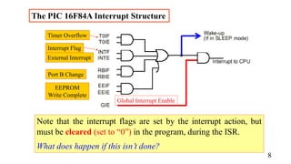
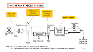
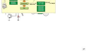
This chapter introduces interrupts, counters, timers and their applications in microcontrollers. It discusses the underlying hardware structures that support interrupts and counting functions. It then describes the specific interrupt and Timer 0 structures in the PIC16F84A microcontroller. Simple programming examples are provided to demonstrate how to use interrupts and Timer 0 for applications like input detection and time delay. The chapter also discusses interrupt latency and techniques like interrupt masking for use in critical program sections.
The document discusses how to handle interrupts in Microchip PIC18F microcontrollers. It explains that peripherals can generate interrupts on events like timer overflow or UART transmission. The microcontroller routes interrupts to the CPU when the global interrupt enable (GIE) bit is set. It provides steps to enable interrupts for a specific peripheral by setting the peripheral's interrupt flag (IF), interrupt enable (IE) bit, and clearing IF after handling the interrupt. Interrupts can optionally use two priority levels by setting the interrupt priority enable (IPEN) bit. The document also gives an example of using timer interrupts to blink an LED based on a pushbutton input.
Subroutines are blocks of code that perform specific tasks and are stored separately from the main program to avoid duplicating code segments. When called, a subroutine will execute its instructions and then return control to the point from which it was called in the main program. Interrupts temporarily halt the main program to allow interrupt service routines (ISRs) to handle priority events, with the processor saving return addresses to resume the main program after interrupts are serviced. PIC microcontrollers have multiple sources of interrupts, each with associated flags to enable interrupts and indicate interrupt requests.
The document discusses the architecture and components of PIC18 microcontrollers. It describes the arithmetic logic unit (ALU) and its associated registers. It explains machine cycles, instruction execution, and pipelining. It also covers oscillators, configuration bits, reset options, low power modes, watchdog timers, and the program counter. It compares Harvard and von Neumann architectures.
Unit 3 timer and counter and there application .pptxnaveen088888
The document discusses timers and interrupts in microcontrollers. It explains that timers can be used to generate time delays by clearing a counter at the start time and waiting for it to reach a certain number. Microcontrollers have multiple timers of different bit sizes that can be used for time delays or event counting. Interrupts temporarily suspend the main program to allow an interrupt service routine to execute, then return to the main program. Sources of interrupts include timers, external pins, serial communication, and analog-to-digital conversion. RS-232 is a common serial interface standard.
This document discusses timers and interrupts on the ATmega328 microcontroller. It describes the digital I/O pins and functions for controlling them. It then covers the different types of interrupts including external interrupts from pins and pin change interrupts. The rest of the document details the timer/counter units 0, 1, and 2, including their registers, modes, and how to configure interrupts from timer events.
This document discusses interrupts in the 8086 microprocessor. It begins by defining an interrupt as an event that temporarily halts normal program execution to divert control to an interrupt service routine. The document then discusses the different types of interrupts in 8086, including hardware interrupts from devices, software interrupts from the INT instruction, maskable interrupts, and non-maskable interrupts. It provides details on how the 8086 handles different interrupt types, such as pushing register values to the stack and jumping to specific memory locations defined in the interrupt vector table.
unit 3 a.pptxpppppppppppppppppppppppppppsachin397946
The document discusses interrupts in PIC18 microcontrollers. It defines interrupts as mechanisms that allow instant response to events. It explains that upon an interrupt, the microcontroller stops executing the main program and jumps to the interrupt service routine (ISR) to handle the interrupt. It discusses different sources of interrupts like external hardware interrupts, timer interrupts and serial communication interrupts. It also explains the steps involved in enabling and disabling interrupts and provides code examples to demonstrate timer and external hardware interrupts.
This document discusses the architecture and operation of processing units. It begins by outlining fundamental concepts like how the processor fetches and executes instructions sequentially using the program counter. It then describes the execution of a single instruction through fetch, execution, and incrementing the program counter phases. The document details the components involved in instruction execution like registers, arithmetic logic unit, and memory. It explains the sequencing of control signals to perform operations like register transfers, arithmetic/logic, and memory access. The document compares hardwired and microprogrammed approaches to control and their advantages/disadvantages. It concludes with details on arithmetic operations like addition, subtraction, overflow detection, and fast addition techniques.
NIE2206 Electronic Logbook
Name: xxx
Student ID: Uxxx
Term: Winter/Spring (delete as appropriate)
By submitting this logbook I confirm that I understand this is an individual assignment and that this work is entirely my own.
Laboratory Practical 1 - XXX
Laboratory Aim
<Briefly paraphrase lab sheet here. Do not simply cut and paste the material>
Exercise 1 - XXX
Aim of exercise
<Write a short aim for the exercise you are about to undertake, what are you going to do in this exercise and why are you doing it?>
Procedure
<Describe the tasks undertaken and evidence they were carried out by:
Answering any questions posed in the lab sheet
Providing code snippets to showing your solution to a coding exercise
Describing your approach to the code design including noting any calculations
Noting any problems e.g. debugging
Note: You must show evidence that you have completed the set tasks in order to gain credit.>
Remember: Context is the key here. It should be possible for a reader to understand from your logbook, without reference to the lab sheets:
What you did.
Why you did it.
How you did it.
Enter code listings using a fixed width font. Here I have used the Code style built into this template which uses the Consolas font as well as a compact line spacing to make code listings compact and easy to read.
Insert evidence of calculations using the built-in Word equation editor or a Word plug-in like Mathtype.
x=y/x + c become s + c
Outcomes
<Describe the outcome of the exercise. What did you observe? Was it successful? Any unusual results that may need explaining>
Conclusion
<Briefly summarise what was carried out. Be reflective - what did you learn through completing this exercise?>
Exercise 2 - XXX
Aim of exercise
xxx
Procedure
xxx
Outcomes
xxx
Conclusion
xxx
Exercise 3 - XXX
Aim of exercise
xxx
Procedure
xxx
Outcomes
xxx
Conclusion
xxx
Laboratory Practical 2 - XXX
Laboratory Aim
Xxx
Exercise 1 - XXX
Aim of exercise
xxx
Procedure
xxx
Outcomes
xxx
Conclusion
xxx
Exercise 2 - XXX
Aim of exercise
xxx
Procedure
xxx
Outcomes
xxx
Conclusion
xxx
41
5 Lab 5 – Interrupts (part 1)
5.1 Aim
This laboratory practical will introduce you to the concept of interrupts, which are an important
feature of all modern computer systems, including microcontrollers. This lab will enable you to
comprehend the purpose of interrupts, and the way in which they can be utilised to optimise wasteful
processes such as event polling loops. Consideration of the different hardware interrupts available on
the PIC16F877A will be undertaken in this laboratory practical, and procedures will be developed for
their proper configuration and servicing.
5.2 Learning Outcomes
Comprehension of the concept of interrupts and have knowledge of the hardware
interrupts available on the PIC16F877A.
Knowledge of how interrupts are implemented and serviced on the PIC16F877A.
Ability to develop code that utilises i ...
This document describes the architectural features and peripheral functions of the PIC16F873 microcontroller. It discusses the microcontroller core, which uses a Harvard architecture with separate program and data memory. It then describes the peripheral features including timers, I/O ports, serial communication interfaces, and analog-to-digital converter. Diagrams are included showing the memory map, pin configuration, and block diagrams of timers and serial communication modules. The document provides a detailed overview of the capabilities and operation of the PIC16F873 microcontroller.
Computer Organization : CPU, Memory and I/O organizationAmrutaMehata
This document provides information on CPU, memory, and I/O organization. It begins with an overview of the main components of a computer including the processor unit, memory unit, and input/output unit. It then describes the CPU in more detail including the arithmetic logic unit, control unit, and CPU block diagram. The document discusses the system bus and its various lines. It also covers CPU registers, instruction cycles, and status and control flags. The document provides an overview of instruction set architecture and compares RISC and CISC processor designs.
The document provides an overview of ARM basics including:
- The different CPU modes including user, fast interrupt, interrupt, supervisor, abort, undefined, and system modes.
- The banked registers that are used across modes including the program counter, stack pointer, link register, and current program status register.
- How pipelining works to improve processor throughput by dividing instructions into fetch, decode, and execute stages.
- The different types of exceptions including interrupts, undefined instructions, and how the processor switches modes and handles exceptions.
The document discusses interrupts for the PIC18 microcontroller. It explains that interrupts allow the microcontroller to instantly respond to events like pin changes or timer overflows. When an interrupt occurs, the microcontroller stops executing the main program and jumps to the interrupt service routine (ISR) to handle the interrupt. It provides details on enabling and disabling interrupts, the interrupt vector table, and examples of using interrupts for external pins, timers, and serial communication.
The document discusses interrupts in embedded systems using the ATmega32 microcontroller as an example. It defines an interrupt as a signal that causes the CPU to stop its current execution and jump to an interrupt service routine (ISR) to handle the interrupt event. It describes the interrupt vector table, which stores the addresses of the ISRs. It outlines the steps taken when an interrupt occurs, which includes saving the program counter, jumping to the ISR, executing the ISR code, and returning where it left off. As an example, it shows code for configuring an external interrupt on pin 16 and the corresponding ISR to toggle an output pin.
In this unit we introduce interrupts in processors and microcontrollers. We explain how the UoS processor (which doesn't support interrupts currently) could be extended to support interrupts.
Unit duration: 50mn.
License: LGPL 2.1
This document provides an overview of the PIC microcontroller. It describes the architecture of the PIC16F84 microcontroller, which uses an 8-bit RISC design. It includes descriptions of the CPU, registers, I/O ports, memory organization, instruction set, and addressing modes. The document also covers oscillator options, reset functionality, and programming the microcontroller.
1. The document discusses embedded systems and Microchip PIC microcontrollers. It describes what embedded systems are and provides examples of application areas.
2. It explains the differences between microprocessors and microcontrollers, and discusses the architecture and features of Microchip's PIC microcontrollers.
3. The document provides an overview of programming PIC microcontrollers, including the instruction set, device structure, and basic circuit requirements.
Interrupts on 8086 microprocessor by vijay kumar.kVijay Kumar
The document discusses interrupts in microprocessors. It defines an interrupt as a signal used to halt normal program execution and divert processing to an interrupt service routine (ISR). There are three main types of interrupts: hardware interrupts from external signals, software interrupts from an INT instruction, and error interrupts from issues like divide-by-zero. When an interrupt occurs, the processor pushes registers onto the stack, loads the ISR address from the interrupt vector table, executes the ISR, then pops registers and returns to the main program. Interrupts provide efficient handling of asynchronous events compared to polling.
The document describes several programs written for microcontrollers to perform various tasks:
1) A program to convert packed BCD to ASCII and store the results in registers.
2) A program to display the text "SGBAU ME 1st" on an LCD screen using a microcontroller.
3) A program to multiplex the numbers 1, 2, 2, 4 on a four digit seven segment display using a microcontroller.
4) A program in GNUSim 8085 that performs all basic arithmetic operations like addition, subtraction, multiplication, and division on 8-bit numbers by loading values from memory locations and storing results back to memory locations.
5) A program to exchange
This document provides an introduction to PIC microcontrollers. It discusses that PIC stands for "Programmable Intelligent Computer" and that a PIC microcontroller is a processor with built-in memory and RAM that can be used to control projects. It then lists some of the useful built-in modules of PIC microcontrollers like EEPROM, timers, and analog comparators. The document also discusses why PIC microcontrollers are popular, which includes their low cost, wide availability, and small size. It then provides details on the pins of the common PIC 16F84 microcontroller and describes its registers and peripherals. Finally, it gives a simple code example using ports on the PIC 16F84
The document provides an introduction to the PIC microcontroller including its origins, architecture, and key features. It discusses the PIC16F877A microcontroller in detail including its register file map, pin configuration, status register, and difference compared to the 8051 microcontroller. Examples of writing assembly language code and C code for blinking an LED are also provided.
The document discusses using the Ready-for-PIC board and SDR libraries to interact with the board's peripherals. It covers initializing and using digital I/O lines, timers, and the analog-to-digital converter. The SDR library provides functions to easily initialize and control these components without needing in-depth knowledge of the microcontroller's registers. Interrupts from timers and other peripherals can also be handled using the library functions. Example code is provided to illustrate flashing LEDs using timers and reading pushbuttons.
This document summarizes key topics from Chapter 5 of a book on designing embedded systems with PIC microcontrollers, including:
- Visualizing programs with flow diagrams and state diagrams
- Using program branching, subroutines, and delays
- Implementing logical instructions and look-up tables
- Optimizing assembler code and using advanced simulator features like breakpoints and timing measurements
DEVICE DRIVERS AND INTERRUPTS SERVICE MECHANISM.pdfAkritiPradhan2
An interrupt is triggered by a hardware event like a device becoming ready, and causes the currently running software to stop and an interrupt service routine (ISR) to start. This avoids the processor having to continuously poll devices for status changes. With interrupts, the processor can run other tasks while waiting for a device and be notified instantly by the interrupt when the device is ready. Interrupts improve efficiency over the programmed I/O approach of busy waiting and polling for status changes.
Chp4 introduction to the pic microcontroller copymkazree
The document provides an introduction to the PIC microcontroller, including:
1) It describes the basic components and architecture of microcontrollers compared to microprocessors.
2) It outlines the history and features of the popular PIC microcontroller family from Microchip Technology, including the PIC16F84 model.
3) It explains the core components of the PIC16F84 including ports, memory organization, clock generator, and the central processing unit.
The document discusses various components of microprocessors and peripherals. It provides definitions and explanations of microprocessors, memory devices like ROM, registers like the accumulator, buses, instructions, and machine cycles. It also covers I/O devices like the 8255 PPI, 8279 keyboard interface, 8251 USART, and 8254 timer, describing their components, operating modes, and initialization procedures. The document is a set of questions and answers relating to microprocessor architecture and common peripherals.
Batteries -Introduction – Types of Batteries – discharging and charging of battery - characteristics of battery –battery rating- various tests on battery- – Primary battery: silver button cell- Secondary battery :Ni-Cd battery-modern battery: lithium ion battery-maintenance of batteries-choices of batteries for electric vehicle applications.
Fuel Cells: Introduction- importance and classification of fuel cells - description, principle, components, applications of fuel cells: H2-O2 fuel cell, alkaline fuel cell, molten carbonate fuel cell and direct methanol fuel cells.
Literature Review Basics and Understanding Reference Management.pptxDr Ramhari Poudyal
Three-day training on academic research focuses on analytical tools at United Technical College, supported by the University Grant Commission, Nepal. 24-26 May 2024
Advanced control scheme of doubly fed induction generator for wind turbine us...IJECEIAES
This paper describes a speed control device for generating electrical energy on an electricity network based on the doubly fed induction generator (DFIG) used for wind power conversion systems. At first, a double-fed induction generator model was constructed. A control law is formulated to govern the flow of energy between the stator of a DFIG and the energy network using three types of controllers: proportional integral (PI), sliding mode controller (SMC) and second order sliding mode controller (SOSMC). Their different results in terms of power reference tracking, reaction to unexpected speed fluctuations, sensitivity to perturbations, and resilience against machine parameter alterations are compared. MATLAB/Simulink was used to conduct the simulations for the preceding study. Multiple simulations have shown very satisfying results, and the investigations demonstrate the efficacy and power-enhancing capabilities of the suggested control system.
Using recycled concrete aggregates (RCA) for pavements is crucial to achieving sustainability. Implementing RCA for new pavement can minimize carbon footprint, conserve natural resources, reduce harmful emissions, and lower life cycle costs. Compared to natural aggregate (NA), RCA pavement has fewer comprehensive studies and sustainability assessments.
Understanding Inductive Bias in Machine LearningSUTEJAS
This presentation explores the concept of inductive bias in machine learning. It explains how algorithms come with built-in assumptions and preferences that guide the learning process. You'll learn about the different types of inductive bias and how they can impact the performance and generalizability of machine learning models.
The presentation also covers the positive and negative aspects of inductive bias, along with strategies for mitigating potential drawbacks. We'll explore examples of how bias manifests in algorithms like neural networks and decision trees.
By understanding inductive bias, you can gain valuable insights into how machine learning models work and make informed decisions when building and deploying them.
KuberTENes Birthday Bash Guadalajara - K8sGPT first impressionsVictor Morales
K8sGPT is a tool that analyzes and diagnoses Kubernetes clusters. This presentation was used to share the requirements and dependencies to deploy K8sGPT in a local environment.
ACEP Magazine edition 4th launched on 05.06.2024Rahul
This document provides information about the third edition of the magazine "Sthapatya" published by the Association of Civil Engineers (Practicing) Aurangabad. It includes messages from current and past presidents of ACEP, memories and photos from past ACEP events, information on life time achievement awards given by ACEP, and a technical article on concrete maintenance, repairs and strengthening. The document highlights activities of ACEP and provides a technical educational article for members.
CHINA’S GEO-ECONOMIC OUTREACH IN CENTRAL ASIAN COUNTRIES AND FUTURE PROSPECTjpsjournal1
The rivalry between prominent international actors for dominance over Central Asia's hydrocarbon
reserves and the ancient silk trade route, along with China's diplomatic endeavours in the area, has been
referred to as the "New Great Game." This research centres on the power struggle, considering
geopolitical, geostrategic, and geoeconomic variables. Topics including trade, political hegemony, oil
politics, and conventional and nontraditional security are all explored and explained by the researcher.
Using Mackinder's Heartland, Spykman Rimland, and Hegemonic Stability theories, examines China's role
in Central Asia. This study adheres to the empirical epistemological method and has taken care of
objectivity. This study analyze primary and secondary research documents critically to elaborate role of
china’s geo economic outreach in central Asian countries and its future prospect. China is thriving in trade,
pipeline politics, and winning states, according to this study, thanks to important instruments like the
Shanghai Cooperation Organisation and the Belt and Road Economic Initiative. According to this study,
China is seeing significant success in commerce, pipeline politics, and gaining influence on other
governments. This success may be attributed to the effective utilisation of key tools such as the Shanghai
Cooperation Organisation and the Belt and Road Economic Initiative.
Embedded machine learning-based road conditions and driving behavior monitoringIJECEIAES
Car accident rates have increased in recent years, resulting in losses in human lives, properties, and other financial costs. An embedded machine learning-based system is developed to address this critical issue. The system can monitor road conditions, detect driving patterns, and identify aggressive driving behaviors. The system is based on neural networks trained on a comprehensive dataset of driving events, driving styles, and road conditions. The system effectively detects potential risks and helps mitigate the frequency and impact of accidents. The primary goal is to ensure the safety of drivers and vehicles. Collecting data involved gathering information on three key road events: normal street and normal drive, speed bumps, circular yellow speed bumps, and three aggressive driving actions: sudden start, sudden stop, and sudden entry. The gathered data is processed and analyzed using a machine learning system designed for limited power and memory devices. The developed system resulted in 91.9% accuracy, 93.6% precision, and 92% recall. The achieved inference time on an Arduino Nano 33 BLE Sense with a 32-bit CPU running at 64 MHz is 34 ms and requires 2.6 kB peak RAM and 139.9 kB program flash memory, making it suitable for resource-constrained embedded systems.
Embedded machine learning-based road conditions and driving behavior monitoring
ES-CH6.ppt
1. Chapter 6
Working with Time: Interrupts, Counters and Timers
The aims of this chapter are to introduce:
• Why we need interrupts and counter/timers;
• The underlying interrupt hardware structure;
• The 16F84A interrupt structure;
• How to write simple programs with interrupts;
• The underlying microcontroller counter/timer hardware structure;
• The 16F84A Timer 0 structure;
• Simple applications of the counter/timer;
• The Sleep mode.
Designing Embedded Systems
with PIC Microcontrollers:
Principles and Applications
2nd Edition. Tim Wilmshurst
1
2. An Interrupt Review.
An Interrupt is an external input to the CPU. The interrupt facility
allows the processor to respond rapidly to external changes.
When an Interrupt is detected by the CPU, it:
completes the current instruction,
stores the address of the next instruction, and possibly other
key variables (e.g. contents of Accumulator and Condition
Code Register), onto the stack,
jumps to an interrupt service routine (ISR), whose address is
determined by an "interrupt vector".
2
3. •Many interrupts can be masked, i.e. disabled, by setting a bit in a
control register. some are not maskable.
•If an Interrupt is masked, then there is a possibility that it will not
be detected.
•Therefore there are also Interrupt Flags, bits in SFRs, which are
set whenever an associated interrupt occurs.
An Interrupt Review
3
4. •These record the fact that an interrupt has occurred, even if the
CPU is unable to respond to it.
•An Interrupt that has occurred, but has not received CPU
response, is called a Pending Interrupt.
•In the case of several interrupts, one ISR is completed before the
next interrupt is responded to.
An Interrupt Review … Cont.
4
5. Control SFR(s)
Peripheral
Data Transfer SFR(s)
Microcontroller
Core
"Outside
World"
Interrupt(s)
Microcontroller Interaction with
Peripherals, via SFR and Interrupt
Recalling Interrupt-Related
Points that have already Come up
Interrupt Routine
always starts here
The Reset Vector
5
6. S Q
Int errupt
Flag*
Inte rrupt X
Int errupt X Enable*
Ot her
G
lobal Int errupt
Non-maskabl e
Inte rrupt
Int erru
input s t
CPU
R
(reset by CPU
or program)
* bit s in a S
pecial Funct ion Regist er
int errupt s
maskable
replicated f
or all other m askable interrupts
A Generic Interrupt Structure
6
8. The PIC 16F84A Interrupt Structure
Global Interrupt Enable
External Interrupt
EEPROM
Write Complete
Port B Change
Timer Overflow
Interrupt Flag
Note that the interrupt flags are set by the interrupt action, but
must be cleared (set to “0”) in the program, during the ISR.
What does happen if this isn’t done?
8
11. The PIC 16F84A Interrupt Structure
RA2
RA3
RA4/T0CKI
MCLR
V
RB0/INT
RB1
RB2
RB3 RB4
RB5
RB6
RB7
RA1
RA0
O S C1/CLKIN
O S C2/CLKO UT
V
DD
SS Sup p ly voltage
Oscillator co
Port A, Bit 0
Port A, Bit 1
Port A, Bit 2
Port A, Bit 3
*Port A, Bit 4
Ground
**Port B, Bit 0
Port B, Bit 1
Port B, Bit 2
Port B, Bit 3
Port B, Bit 7
Port B, Bit 6
Port B, Bit 5
Port B, Bit 4
*also Counter/T imer clock inp ut
**also external Interrup t inp ut
Reset
1
9 10
18
External
Interrupt
input
11
12. Interrupt Detected
Complete Current Instruction
Save Program Counter on Stack
Reload PC with 0004H
Continue Program Execution
Instruction
is RETFIE?
No
Set GIE to 1
Load PC from Stack
Continue Program Execution
Yes
Clear GIE
ISR execution starts
main program is running
main program continues
The PIC 16 Series Interrupt Response
• Note that this diagram shows what the
PIC microcontroller itself does as an
interrupt occurs.
• The programmer need not worry about
any of these actions, but needs to
know that they’re happening.
Interrupt Detected
Complete Current Instruction
Save Program Counter on Stack
Reload PC with 0004H
Continue Program Execution
Instruction
is RETFIE?
No
Set GIE to 1
Load PC from Stack
Continue Program Execution
Yes
Clear GIE
ISR execution starts
main program is running
main program continues
12
13. Programming with Single Interrupts
It is easy to write simple programs with just one interrupt. For
success, the essential points to watch are:
• Start the ISR at the Interrupt Vector, location 0004;
• Enable the interrupt that is to be used, by setting enable bits in
the INTCON and/or PIE (Peripheral Interrupt Enable) registers;
• Set the Global Enable bit, GIE;
• Once in the ISR, clear the interrupt flag;
• End the ISR with a retfie instruction;
• Ensure that the interrupt source, for example Port B or Timer 0, is
actually set up to generate interrupts!
13
14. org 00
goto start
org 04 ;here if interrupt occurs
goto Int_Routine
start
org 0010
;bcf option_reg,intedg
bcf STATUS,RP0 ;select bank 0
bsf INTCON,INTE ;enable external interrupt
bsf INTCON,GIE ;enable global int
wait movlw 0A ;set up initial port output values
movwf porta
nop
movlw 15
movwf porta
goto wait
org 0080
Int_Routine
movlw 00
movwf porta
bcf INTCON,INTF ;clear the interrupt flag
RETFIE
end
A Simple Interrupt
Application
14
15. The INTCON Register of a PIC 16F84A is set as shown in below:
a) Determine which interrupts are enabled.
b) An interrupt occurs, and the INTCON register is found to have
changed to b).
Which interrupt source has called?
c) Which bit must the user change before end of ISR?
IN
TCON IN
TCON
1
0
1
0
1
0
0
0 1
0
1 1
0 0
0
1
Interrupt Example 1
a) b)
15
16. Moving to Multiple Interrupts – Identifying the Source
As we have seen, the 16F84A has four interrupt sources, but only
one interrupt vector.
Therefore, if more than one interrupt is enabled, it is not obvious at
the beginning of an ISR which interrupt has occurred. In this case
the programmer must write the ISR so that at its beginning it tests
the flags of all possible interrupts and determines from this which
one has been called, This is shown in the example ISR below.
16
17. Interrupt
btfsc intcon,0 ;test RBIF
goto portb_int
btfsc intcon,1 ;test external interrupt flag
goto ext_int
btfsc intcon,2 ;test timer overflow flag
goto timer_int
retfie
portb_int
place portb change ISR here ...
bcf intcon,0 ;and clear the interrupt flag
retfie
ext_int
place external interrupt ISR here ...
bcf intcon,1 ;and clear the interrupt flag
retfie
timer_int
place timer overflow ISR goes here ...
bcf intcon,2 ;and clear the interrupt flag
retfie
Moving to Multiple
Interrupts –
Identifying the Source
17
18. Critical Regions and Masking
In certain program parts we will not want to accept the intrusion of an interrupt
under any circumstances, with or without context saving. We call these critical
regions. We can disable, or mask, the interrupts for their duration, by
manipulating the enable bits in the INTCON register.
Critical regions may include:
1. times when the microcontroller is simply not ready to act on the interrupt
(for example during initialization – hence only enable interrupts after
initialization is complete);
2. time-sensitive activity, including timing loops and multi-instruction setting
of outputs;
3. any calculation made up of a series of instructions where the ISR makes
use of the result. 18
19. The purpose of the interrupt is to attract the attention of the CPU
quickly, but actually how quickly does this happen? The time
between the interrupt occurring and the CPU responding to it is
called the latency.
This depends on certain aspects of hardware and on the
characteristics of the program running. This timing diagram shows
how the mid-range PIC family responds to an enabled external
interrupt.
Taking Things Further: Interrupt Latency
19
20. The Digital Counter Reviewed
• It is easy to make a digital counter using flip-flops.
• Counters can be made which count up, count down, which can
be cleared back to zero, pre-loaded to a certain value, and which
by the provision of an overflow output can be cascaded with
other counters. A simple example is shown:
21
25. The Counter as Timer
• If the incoming clock pulses are regular in frequency, the
counter can also measure time.
• In this example time is being measured between two pulses.
Clock
Pulse Input
T
1 2 3 4 5 n
Tc
26
26. Clock
Pulse Input
T
1 2 3 4 5 n
Tc
The Counter as Timer
If TC is clock period, and n cycles are counted, then the period during which
counting has taken place is nTC .
Example: clock frequency is 1 MHz, clock period is therefore 1us, before
overflow counter can count:
8-bit 255us
16-bit 65535us = 65.5ms
24-bit 16.78 secs
32-bit 4,295 secs = 1hr, 11minutes 27
27. Timer Prescalar
28
A prescaler is an electronic counting circuit used to reduce a
high frequency electrical signal to a lower frequency by integer
division.