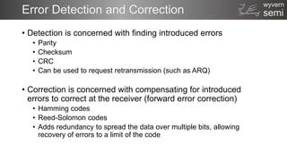
This document discusses error detection and correction techniques for digital communication and storage. It covers basic detection methods like parity and checksums. It then discusses more advanced error correction codes like Hamming codes, which can detect and correct single bit errors. Reed-Solomon codes are also covered, which can detect and correct multiple symbol errors and are used in applications like CDs and DVDs. Logic implementations for Hamming encoders, decoders and Reed-Solomon encoders are shown at a high level.


![semi
wyvern
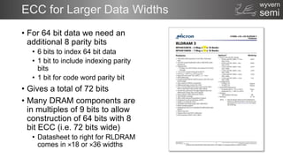
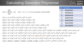
Basic Detection
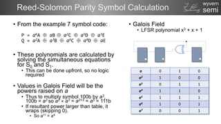
• Parity
• XOR (or XNOR) data bits to
produce a parity bit.
• Even or Odd
• Can detect only 1 bit error.
• Good for channels with disparate
random low level noise
• Checksum
• Add together data words in a
block, modulo checksum width
• E.g. Add bytes over 4Kbyte block to
produce a 32 bit checksum (i.e.
module. 232)
• Performance is a function of block
size and checksum width.
// Parity
wire [7:0] byte;
wire parity_even = ^byte;
wire parity_odd = ~^byte;
// Check sum (behavioural)
reg [7:0] data [0:255];
reg [15:0] chksum = 16'h0000;
integer i;
always (posedge clk)
begin
for(i = 0; i < 256; i = i+1)
chksum = chksum + data[i];
end](https://image.slidesharecdn.com/errordetectioncorrection-230519100956-93702c41/85/error_detection_correction-pptx-3-320.jpg)
![semi
wyvern
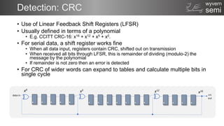
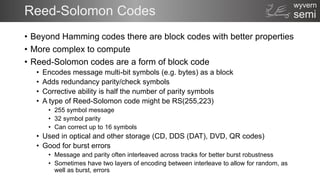
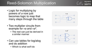
Encoder Logic for Hamming Code
// ------------------------------
// Encoder
// ------------------------------
module hamming8_encoder(
input [7:0] data,
output [12:0] code);
wire p1 = data[0] ^ data[1] ^ data[3] ^ data[4] ^ data[6];
wire p2 = data[0] ^ data[2] ^ data[3] ^ data[5] ^ data[6];
wire p4 = data[1] ^ data[2] ^ data[3] ^ data[7];
wire p8 = data[4] ^ data[5] ^ data[6] ^ data[7];
wire [11:0] hamm_code = {data[7], data[6], data[5], data[4], p8, data[3],
data[2], data[1], p4, data[0], p2, p1};
wire parity = ^hamm_code;
assign code = {parity, hamm_code};
endmodule
full code, with comments and TB at: http://www.anita-simulators.org.uk/ecc.zip](https://image.slidesharecdn.com/errordetectioncorrection-230519100956-93702c41/85/error_detection_correction-pptx-7-320.jpg)
![semi
wyvern
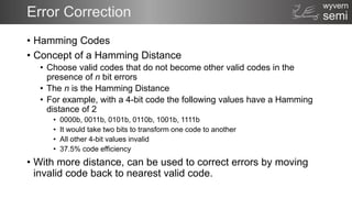
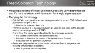
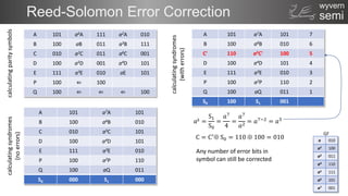
Decoder Logic for Hamming Code
// ------------------------------
// Decoder
// ------------------------------
module hamming8_decoder (
input [12:0] code,
output [7:0] data,
output error);
wire [3:0] e;
assign e[0] = code[0] ^ code[2] ^ code[4] ^ code[6] ^ code[8] ^ code[10];
assign e[1] = code[1] ^ code[2] ^ code[5] ^ code[6] ^ code[9] ^ code[10];
assign e[2] = code[3] ^ code[4] ^ code[5] ^ code[6] ^ code[11];
assign e[3] = code[7] ^ code[8] ^ code[9] ^ code[10] ^ code[11];
wire [15:0] flip_mask = 16'h0001 << e;
wire [11:0] corr_code = code[11:0] ^ flip_mask[12:1];
wire corr_parity = ^{code[12], corr_code};
assign data = {corr_code[11], corr_code[10], corr_code[9], corr_code[8],
corr_code[6], corr_code[5], corr_code[4], corr_code[2]};
// Error if parity on a corrected code fails, or index into codeword invalid (i.e. > 12)
assign error = (|e & corr_parity) | (|flip_mask[15:13]);
endmodule
full code, with comments and TB at: http://www.anita-simulators.org.uk/ecc.zip](https://image.slidesharecdn.com/errordetectioncorrection-230519100956-93702c41/85/error_detection_correction-pptx-8-320.jpg)
![semi
wyvern
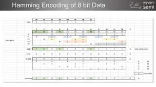
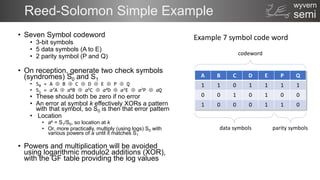
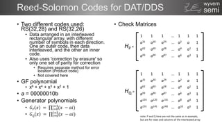
Reed-Solomon encoder (RS(7,5))
module rs_7_5_encoder
(
input [14:0] idata,
output[20:0] ocode
);
wire [2:0] s [0:6];
integer idx;
reg [2:0] GF_log [1:7];
reg [2:0] GF_alog [1:7];
reg [2:0] p_poly [0:4];
reg [2:0] q_poly [0:4];
reg [3:0] p_data [0:4];
reg [3:0] q_data [0:4];
reg [2:0] P, Q;
assign s[0] = idata[2:0];
assign s[1] = idata[5:3];
assign s[2] = idata[8:6];
assign s[3] = idata[11:9];
assign s[4] = idata[14:12];
assign s[5] = P;
assign s[6] = Q;
assign ocode = {s[6], s[5], s[4], s[3],
s[2], s[1], s[0]};
initial
begin
// Galois field for x3 + x + 1
GF_alog[1] = 3'b010; GF_alog[2] = 3'b100;
GF_alog[3] = 3'b011; GF_alog[4] = 3'b110;
GF_alog[5] = 3'b111; GF_alog[6] = 3'b101;
GF_alog[7] = 3'b001;
// Inverse (log) Galois field for
// x3 + x + 1
GF_log[1] = 3'b111; GF_log[2] = 3'b001;
GF_log[3] = 3'b011; GF_log[4] = 3'b010;
GF_log[5] = 3'b110; GF_log[6] = 3'b100;
GF_log[7] = 3'b101;
// Corrector polynomial (log):
// a6 + a + a2 + a5 + a3
p_poly[0] = 6; p_poly[1] = 1;
p_poly[2] = 2; p_poly[3] = 5;
p_poly[4] = 3;
// Locator polynomial (log):
// a2 + a3 + a6 + a4 + a
q_poly[0] = 2; q_poly[1] = 3;
q_poly[2] = 6; q_poly[3] = 4;
q_poly[4] = 1;
end
always @(*)
begin
P = 3'b000;
Q = 3'b000;
for (idx = 0; idx < 5; idx = idx + 1)
begin
// Calulate P
p_data[idx] = p_poly[idx] + GF_log[s[idx]];
p_data[idx] = p_data[idx][2:0] + p_data[idx][3];
p_data[idx] = GF_alog[p_data[idx]];
P = P ^ p_data[idx];
// Calculate Q
q_data[idx] = q_poly[idx] + GF_log[s[idx]];
q_data[idx] = q_data[idx][2:0] + q_data[idx][3];
q_data[idx] = GF_alog[q_data[idx]];
Q = Q ^ q_data[idx];
end
end
endmodule
full code, with comments and TB at: http://www.anita-simulators.org.uk/ecc.zip](https://image.slidesharecdn.com/errordetectioncorrection-230519100956-93702c41/85/error_detection_correction-pptx-16-320.jpg)
![semi
wyvern
Reed-Solomon decoder (RS(7,5))
module rs_7_5_decoder
(
input [20:0] icode,
output [14:0] odata
);
reg [2:0] s [0:6];
integer idx;
reg [2:0] GF_log [1:7];
reg [2:0] GF_alog [1:7];
reg [3:0] S1_poly [0:6];
reg [3:0] k;
reg [2:0] S0;
reg [2:0] S1;
assign odata = {s[4], s[3], s[2], s[1], s[0]};
initial
begin
// Galois field for x3 + x + 1
GF_alog[1] = 3'b010; GF_alog[2] = 3'b100;
GF_alog[3] = 3'b011; GF_alog[4] = 3'b110;
GF_alog[5] = 3'b111; GF_alog[6] = 3'b101;
GF_alog[7] = 3'b001;
// Inverse (log) Galois field for
// x3 + x + 1
GF_log[1] = 3'b111; GF_log[2] = 3'b001;
GF_log[3] = 3'b011; GF_log[4] = 3'b010;
GF_log[5] = 3'b110; GF_log[6] = 3'b100;
GF_log[7] = 3'b101;
end
always @(icode)
begin
s[0] = icode[2:0]; s[1] = icode[5:3];
s[2] = icode[8:6]; s[3] = icode[11:9];
s[4] = icode[14:12]; s[5] = icode[17:15];
s[6] = icode[20:18];
S0 = s[0] ^ s[1] ^ s[2] ^ s[3] ^
s[4] ^ s[5] ^ s[6];
S1 = 3'b000;
for (idx = 0; idx < 7; idx = idx + 1)
begin
S1_poly[idx] = (7 - idx) + GF_log[s[idx]];
S1_poly[idx] = S1_poly[idx][2:0] + S1_poly[idx][3];
S1_poly[idx] = s[idx] ? GF_alog[S1_poly[idx]] : 3'b000;
S1 = S1 ^ S1_poly[idx];
end
if (S0 != 3'b000)
begin
k = GF_log[S1] - GF_log[S0];
k = k[2:0] - k[3];
k = (k == 4'b0000) ? GF_log[3'b001] : k;
s[7-k] = s[7-k] ^ S0;
end
end
endmodule
full code, with comments and TB at: http://www.anita-simulators.org.uk/ecc.zip](https://image.slidesharecdn.com/errordetectioncorrection-230519100956-93702c41/85/error_detection_correction-pptx-17-320.jpg)

![semi
wyvern
References
[1] Hamming, R.W., Error-detecting and error-correcting codes. Bell System
Tech. J., 26,147–160 (1950)
[2] Watkinson, J., The Art of Digital Audio (3rd Edition), Focal Press (2001)
[3] Anon., Standard ECMA-139, 3,81mm Wide Magnetic Tape Cartridge for
Information Interchange – Helical Scan Recording – DDS Format, ECMA
(June 1990)](https://image.slidesharecdn.com/errordetectioncorrection-230519100956-93702c41/85/error_detection_correction-pptx-20-320.jpg)


![[Deck] What's New in Spark-Iceberg Integration via DSV2.pptx](https://cdn.slidesharecdn.com/ss_thumbnails/deckwhatsnewinspark-icebergintegrationviadsv2-260210005337-25955b12-thumbnail.jpg?width=640&height=640&fit=bounds)