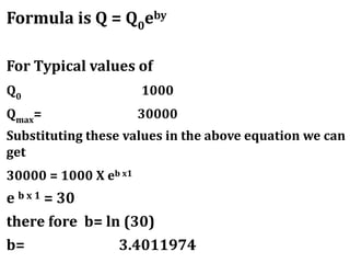
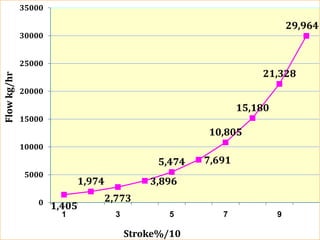
This document discusses the relationship between valve opening percentage and flow for an equal percentage valve. It provides the formula Q = Q0 * e^bY, where Q is the flow, Q0 is the initial flow, Y is the valve opening percentage, and b is a constant determined by the maximum flow. The document then applies this formula using sample values and graphs the resulting flow at each 10% valve opening from 10-100%.
Pressure Safety Valve Sizing - API 520/521/526Vijay Sarathy
No chemical process facility is immune to the risk of overpressure to avoid dictating the necessity for overpressure protection. For every situation that demands safe containment of process gas, it becomes an obligation for engineers to equally provide pressure relieving and flaring provisions wherever necessary. The levels of protection are hierarchical, starting with designing an inherently safe process to avoid overpressure followed by providing alarms for operators to intervene and Emergency Shutdown provisions through ESD and SIL rated instrumentation. Beyond these design and instrument based protection measures, the philosophy of containment and abatement steps such as pressure relieving devices, flares, physical dikes and Emergency Response Services is employed
Excel sheet Download Link: https://www.scribd.com/document/385945712/PSV-Sizing-Tool-API-Based-Calc-Sheets
PSV Sizing for Blocked Liquid Discharge Condition
PSV Sizing for Blocked Gas Discharge Condition
PSV Sizing for Fire Case of Liquid Filled Vessel
PSV Sizing for Control Valve Fail Open Case
Relief Valve Sizing for Thermal Expansion
Restriction Orifice Sizing for Gas Flow
Restriction Orifice Sizing for Liquid Flow
Single Phase Flow Line Sizing Tool
Gas Control Valve Sizing Tool
Selection and Design of Condensers
0 INTRODUCTION/PURPOSE
1 SCOPE
2 FIELD OF APPLICATION
3 DEFINITIONS
4 CHOICE OF COOLANT
5 LAYOUT CONSIDERATIONS
5.1 Distillation Column Condensers
5.2 Other Process Condensers
6 CONTROL
6.1 Distillation Columns
6.2 Water Cooled Condensers
6.3 Refrigerant Condensers
7 GENERAL DESIGN CONSIDERATIONS
7.1 Heat Transfer Resistances
7.2 Pressure Drop
7.3 Handling of Inerts
7.4 Vapor Inlet Design
7.5 Drainage of Condensate
8 SUMMARY OF TYPES AVAILABLE
8.1 Direct Contact Condensers
8.2 Shell and Tube Exchangers
8.3 Air Cooled Heat Exchangers
8.4 Spiral Plate Heat Exchangers
8.5 Internal Condensers
8.6 Plate Heat Exchangers
8.7 Plate-Fin Heat Exchangers
8.8 Other Compact Designs
9 BIBLIOGRAPHY
FIGURES
1 DIRECT CONTACT CONDENSER WITH INDIRECT COOLER FOR RECYCLED CONDENSATE
2 SPRAY CONDENSER
3 TRAY TYPE CONDENSER
4 THREE PASS TUBE SIDE CONDENSER WITH INTERPASS LUTING FOR CONDENSATE DRAINAGE
5 CROSS FLOW CONDENSER WITH SINGLE PASS COOLANT
Basic Unit Conversions for Turbomachinery Calculations Vijay Sarathy
Turbomachinery equipment like centrifugal pumps & compressors have their performance stated as a function of Actual volumetric flow rate [Q] & Head [m/bar]. The following tutorial describes how pump/compressor head can be expressed in energy terms as ‘kJ/kg’. Turbomachinery head expressed in kJ/kg describes, how many kJ of energy is required to compress 1 kg of gas for a given pressure ratio. The advantage of using energy terms to estimate absorbed power is that it is based on the amount of ‘mass’ compressed which is independent of pressure and temperature of a fluid.
This was one of the very first CBT modules I developed. This presentation was imported into Captivate, where additional features such as mouse-over definitions were added.
Engineers often use softwares to perform gas compressor calculations to estimate compressor duty, temperatures, adiabatic & polytropic efficiencies, driver & cooler duty. In the following exercise, gas compressor calculations for a pipeline composition are shown as an example case study.
Amine Gas Treating Unit - Best Practices - Troubleshooting Guide Gerard B. Hawkins
Amine Gas Treating Unit Best Practices - Troubleshooting Guide for H2S/CO2 Amine Systems
Contents
Process Capabilities for gas treating process
Typical Amine Treating
Typical Amine System Improvements
Primary Equipment Overview
Inlet Gas Knockout
Absorber
Three Phase Flash Tank
Lean/Rich Heat Exchanger
Regenerator
Filtration
Amine Reclaimer
Operating Difficulties Overview
Foaming
Failure to Meet Gas Specification
Solvent Losses
Corrosion
Typical Amine System Improvements
Degradation of Amines and Alkanolamines during Sour Gas Treating
APPENDIX
Best Practices - Troubleshooting Guide
Safety is the most important factor in designing a process system. Some undesired conditions might happen leading to damage in a system. Control systems might be installed to prevent such conditions, but a second safety device is also needed. One kind of safety device which is commonly used in the processing industry is the relief valve. A relief valve is a type of valve to control or limit the pressure in a system by allowing the pressurised fluid to flow out from the system.
Water steam Circuit in Supercritical Boiler for 660MW Power PlantHareesh VS
An animated presentation over Complete water steam circulation in a super critical boiler with flow chart. The water-steam path through various Systems (High pressure & Low pressure systems) in boiler for a 660MW thermal power plat, and also indicates the temperature and pressure variations after flowing through individual systems. Watch Live Presentation on YouTube: http://youtu.be/snIVrTmI4bM
Pressure Relief Valve Sizing for Single Phase FlowVikram Sharma
This presentation file provides a quick refresher to pressure relief valve sizing for single phase flow. The calculation guideline is as per API Std 520.
The explosion hazard in urea process (1)Prem Baboo
In Urea plant passivation air is used in reactor, stripper and downstream of the all equipments. The reactor liner material used Titanium, Zirconium, SS 316L (urea grade), 2RE-69 and duplex material .except Titanium and Zirconium all stainless steel required more passivation air. In CO2 some quantity of Hydrogen is present about 0.14% to 0.2% . The passivation oxygen and Hydrogen makes explosive mixture. To avoid a fire or explosion in a process vessel is to introduce inert (noncombustible) gases in such a way that there is never a mixture with a combustible concentration in exit of MP vent. Mixtures of fuel, oxygen, and inert gases are not combustible over the entire range of composition. In CO2 stripping process the HP scrubber is the risky vessel and this vessel consisting blanketing sphere, Heat exchanger part and a scrubbing part. With help of triangular diagram that shows the shape of the combustible/noncombustible regions for a typical gaseous mixture of fuel, oxygen, and inert at specified temperature and pressure. Present article how to avoid that combustible rang and how to tackle that gases in CO2 & ammonia stripping process.
Over the past two decades, the ammonia and urea industry have witnessed spectacular metallurgical developments for process equipment. For example, stainless steels, modified with special materials, can improve high temperature creep rupture resistance. Using duplex stainless steels and modern corrosion abatement techniques are other methods that improve plant-operating performance.
Ever since the declaration of 100% neem coated urea by India Government, the number of neem trees is increasing continuously in India Neem coated urea requires neem oil, more urea more oil and trees also required more. When it comes to oil, neem plants are rather promising. Probably no other plant yields as many exploitable by-products and benefits. Earlier, 100% Neem Coated Urea was made mandatory in 2015.
Prills /granular urea are not only costly for the producer but may be harmful to humans and the environment. Furthermore, nano Urea may also be used for enhancing abiotic stress tolerance. Nano-Urea prevents environmental pollution and improves physiological traits of wheat grown under drought stress conditions. The nano urea consist of higher surface area because lesser in size of the nano particle and have high reactivity, solubility in water. Nano Urea are the important tools in agriculture to improve crop efficiency, yield and quality parameters with increase nutrient use efficiency, reduce wastage of fertilizers and cost of cultivation. Nano-urea is very effective for precise nutrient management in precision agriculture with matching the crop growth stage for nutrient and may provide nutrient throughout the crop growth period. Nano-Urea increase crop growth up to optimum concentrations further increase in concentration may inhibit the crop growth due to the toxicity of nutrient. Nano-Urea provide more surface area for different metabolic reactions in the plant which increase rate of photosynthesis and produce more dry matter and yield of the crop. It is also prevent plant from different biotic and abiotic stress.
Installation of S-50 ammonia synthesis converter along with waste heat boiler in downstream of existing S-200 ammonia synthesis converter is one of the major schemes of Energy Saving Project of Ammonia plant. The energy saving reported 0.18 G.Cal/T of Ammonia. Several ammonia plants have installed an additional ammonia synthesis converter in combination with a HP steam waste heat boiler, downstream of the existing ammonia converter. The result is increased conversion per pass, reduced compression requirements due to the smaller recycle gas stream, and improved waste heat recovery. Among the methodologies aimed at finding energy saving opportunities, pinch analysis linked to power and steam modeling has proved to be a powerful way for determining projects to improve the overall energy efficiency of industrial sites. This procedure has been applied successfully in many industrial facilities, allowing optimal energy recovery in the process and hence reduction of fuel consumption.
Super conversion in urea reactors with super cup high efficiency traysPrem Baboo
In Urea Conversion gas/liquid mixing in urea reactor with application of high efficiency trays homogeneous and heterogeneous phases’ iquilibria and kinetics is very important. The efficiency of Urea Reactors can be improved by the application of the latest generation of internals .Generally Fluid dynamics phenomenon are created by the concurrent gas liquid flow through the simple perforated trays which generates irregular bubbles now this problem has been solved by new generation high efficiency device super cup patented by M/S. Saipem. Present article intended how conversion increases by super cup with geometry of the shape of super cup etc. The increase in the efficiency has permitted direct benefits to the overall production and energy of the units, thus allowing lower energy consumption and a reduced environmental impact emission of greenhouse gases. The Super Cups can be applied to design a new generation of urea reactors as well as to improve the performance of existing equipment in a revamp design.
In the plant, ammonia is produced from synthesis gas containing hydrogen and nitrogen in the ratio of approximately 3:1. Besides these components, the synthesis gas contains inert gases such as argon and methane to a limited extent. The source of H2 is demineralized water and the hydrocarbons in the natural gas. The source of N2 is the atmospheric air. The source of CO2 is the hydrocarbons in the natural gas feed. Product ammonia and CO2 is sent to urea plant. The present article intended the description of ammonia plant for natural gas based plants and the possible material balance of some section.
Sweet and sour experience of commissioning 1Prem Baboo
The paper describes a successful of plant start-up despite the pandemic difficulties and introduces a set of first considerations about the possible future application of available digital technologies for remote and distributed control system from central control room commissioning of complex Dangote Fertilizer Plants. The numbers of problem were faced during commissioning stage ultimately the 17th march 2021 was the historical date for achieved plant production of line-1 plant .The major problem was pandemic due to which scarcity of staff availability. However numbers of problems faced in Ammonia and urea plants. About 4 time’s unsuccessful attempt were done and finally we got historical success. In this paper we described the failure attempt and types of problems faced in ammonia and urea plants and each time problems were differ from previous.
How to improve safety and reliability of the high pressure section of urea pl...Prem Baboo
This paper elaborates the most critical safety hazards: Ruptures and toxic ammonia leaks. The paper also provides the Top 10 prevention and mitigation measures. To minimize / avoid that incidents do repeat, we recommend to make use of the Center for Chemical Process Safety: Risk Based Process Safety Management approach. Pay proper attention to avoid ruptures, to handle leaks and to apply the right and state-of-the-art leak detection systems.
Experience of material in fertilizers industriesPrem Baboo
Materials plays very important role in any industry. Selection of material is vital at design stage itself ,Wrong selection of material may lead to catastrophic failures and outage of plants & even loss of Human lives, Right selection of material leads to long life of plant. In the latest plants specialty 2 RE-69 materials are used for liner. The actual reactor has been constructed using a variety of materials, e.g. Zirconium, Vessel inside a protective liner. This paper intended study Material in urea plant in different vessels and equipment design. In Primary reformer numbers of materials are modified such as micro alloy are also used in tubes.
This book covers design of high Pressure equipment and developments, Process flow diagram of different section of Ammonia, Urea and others fertilizers .Fundamentals of ammonia urea plant trouble shooting risk assessment corrosion in different vessels and remedies. This book is useful for Engineers and Sr. Managers for plant commissioning and trouble shooting and Engineering Students. This book contains about 51 tables and 144 useful diagram and chart graphics etc. Detail description of ammonia/CO2 stripping process and new developments. Design Parameters of High pressure vessel and comparison. Study of corrosion for various equipments and control. How to control corrosion by changing of equipments material.
High pressure vessel_leakage_in_urea_plants (1)Prem Baboo
In urea plant ammonium carbamate solution is very corrosive; all metals have corrosion problems with ammonium carbamate and the corrosion problems increase with temperature, a ten degree Celsius rise in temperature doubles the corrosion rate to the point where the duplex steel is no longer acceptable. The material plays a very important role in Urea plants. The space between the reactor liner and the shell is most often empty and employs various methods of detecting a leak ranging from conductivity measurements. Vacuum leak detection system, pressure leak detection system etc. Titanium, SS316L (urea grade), 2 RE-69 etc.) Over the years that can resist ammonium carbamate corrosion. Materials plays very important role in any industry. Selection of material is vital at design stage itself ,Wrong selection of material may lead to catastrophic failures and outage of plants & even loss of Human lives, Right selection of material leads to long life of plant. In the latest plants specialty duplex materials are used for liner. The actual reactor has been constructed using a variety of materials, e.g. Zirconium, Vessel inside a protective liner. This paper intended study of number of leakage in the HP loop vessels, e.g. Zirconium, Vessel inside a protective liner. This paper intended study of number of leakage in the HP loop vessels, e.g. Reactor, Stripper, Carbamate condenser etc. How to detect leakage and troubleshooting during detection and attending the leakages.
High pressure vessel leakage in urea plantsPrem Baboo
In urea plant ammonium carbamate solution is very corrosive; all metals have corrosion problems with ammonium carbamate and the corrosion problems increase with temperature, a ten degree Celsius rise in temperature doubles the corrosion rate to the point where the duplex steel is no longer acceptable. The material plays a very important role in Urea plants. The space between the reactor liner and the shell is most often empty and employs various methods of detecting a leak ranging from conductivity measurements. Vacuum leak detection system, pressure leak detection system etc. Titanium, SS316L (urea grade), 2 RE-69 etc.) Over the years that can resist ammonium carbamate corrosion. Materials plays very important role in any industry. Selection of material is vital at design stage itself ,Wrong selection of material may lead to catastrophic failures and outage of plants & even loss of Human lives, Right selection of material leads to long life of plant. In the latest plants specialty duplex materials are used for liner. The actual reactor has been constructed using a variety of materials, e.g. Zirconium, Vessel inside a protective liner. This paper intended study of number of leakage in the HP loop vessels, e.g. Zirconium, Vessel inside a protective liner. This paper intended study of number of leakage in the HP loop vessels, e.g. Reactor, Stripper, Carbamate condenser etc. How to detect leakage and troubleshooting during detection and attending the leakages.
If the material of liner changed with 2RE 69 or Duplex material instead of SS316(urea grade), then passivation air can be reduced, resulting the energy saving because the inerts vented from M.P section and loss of ammonia and problem of pollution. To enhance capacity and energy of the existing plant the internals like vortex mixture and HET may be changed the capacity may increase up to 10-15%.HET, you can changed with super cup.The CO2 and feed top of the vortex mixture nozzle and Ammonia plus carbamate feed from side of the vortex mixture. In the mixing area the initial dispersion of gas and formation of liquid – gas mixture are performed.
Hybrid optimization of pumped hydro system and solar- Engr. Abdul-Azeez.pdffxintegritypublishin
Advancements in technology unveil a myriad of electrical and electronic breakthroughs geared towards efficiently harnessing limited resources to meet human energy demands. The optimization of hybrid solar PV panels and pumped hydro energy supply systems plays a pivotal role in utilizing natural resources effectively. This initiative not only benefits humanity but also fosters environmental sustainability. The study investigated the design optimization of these hybrid systems, focusing on understanding solar radiation patterns, identifying geographical influences on solar radiation, formulating a mathematical model for system optimization, and determining the optimal configuration of PV panels and pumped hydro storage. Through a comparative analysis approach and eight weeks of data collection, the study addressed key research questions related to solar radiation patterns and optimal system design. The findings highlighted regions with heightened solar radiation levels, showcasing substantial potential for power generation and emphasizing the system's efficiency. Optimizing system design significantly boosted power generation, promoted renewable energy utilization, and enhanced energy storage capacity. The study underscored the benefits of optimizing hybrid solar PV panels and pumped hydro energy supply systems for sustainable energy usage. Optimizing the design of solar PV panels and pumped hydro energy supply systems as examined across diverse climatic conditions in a developing country, not only enhances power generation but also improves the integration of renewable energy sources and boosts energy storage capacities, particularly beneficial for less economically prosperous regions. Additionally, the study provides valuable insights for advancing energy research in economically viable areas. Recommendations included conducting site-specific assessments, utilizing advanced modeling tools, implementing regular maintenance protocols, and enhancing communication among system components.
NO1 Uk best vashikaran specialist in delhi vashikaran baba near me online vas...Amil Baba Dawood bangali
Contact with Dawood Bhai Just call on +92322-6382012 and we'll help you. We'll solve all your problems within 12 to 24 hours and with 101% guarantee and with astrology systematic. If you want to take any personal or professional advice then also you can call us on +92322-6382012 , ONLINE LOVE PROBLEM & Other all types of Daily Life Problem's.Then CALL or WHATSAPP us on +92322-6382012 and Get all these problems solutions here by Amil Baba DAWOOD BANGALI
#vashikaranspecialist #astrologer #palmistry #amliyaat #taweez #manpasandshadi #horoscope #spiritual #lovelife #lovespell #marriagespell#aamilbabainpakistan #amilbabainkarachi #powerfullblackmagicspell #kalajadumantarspecialist #realamilbaba #AmilbabainPakistan #astrologerincanada #astrologerindubai #lovespellsmaster #kalajaduspecialist #lovespellsthatwork #aamilbabainlahore#blackmagicformarriage #aamilbaba #kalajadu #kalailam #taweez #wazifaexpert #jadumantar #vashikaranspecialist #astrologer #palmistry #amliyaat #taweez #manpasandshadi #horoscope #spiritual #lovelife #lovespell #marriagespell#aamilbabainpakistan #amilbabainkarachi #powerfullblackmagicspell #kalajadumantarspecialist #realamilbaba #AmilbabainPakistan #astrologerincanada #astrologerindubai #lovespellsmaster #kalajaduspecialist #lovespellsthatwork #aamilbabainlahore #blackmagicforlove #blackmagicformarriage #aamilbaba #kalajadu #kalailam #taweez #wazifaexpert #jadumantar #vashikaranspecialist #astrologer #palmistry #amliyaat #taweez #manpasandshadi #horoscope #spiritual #lovelife #lovespell #marriagespell#aamilbabainpakistan #amilbabainkarachi #powerfullblackmagicspell #kalajadumantarspecialist #realamilbaba #AmilbabainPakistan #astrologerincanada #astrologerindubai #lovespellsmaster #kalajaduspecialist #lovespellsthatwork #aamilbabainlahore #Amilbabainuk #amilbabainspain #amilbabaindubai #Amilbabainnorway #amilbabainkrachi #amilbabainlahore #amilbabaingujranwalan #amilbabainislamabad
Cosmetic shop management system project report.pdfKamal Acharya
Buying new cosmetic products is difficult. It can even be scary for those who have sensitive skin and are prone to skin trouble. The information needed to alleviate this problem is on the back of each product, but it's thought to interpret those ingredient lists unless you have a background in chemistry.
Instead of buying and hoping for the best, we can use data science to help us predict which products may be good fits for us. It includes various function programs to do the above mentioned tasks.
Data file handling has been effectively used in the program.
The automated cosmetic shop management system should deal with the automation of general workflow and administration process of the shop. The main processes of the system focus on customer's request where the system is able to search the most appropriate products and deliver it to the customers. It should help the employees to quickly identify the list of cosmetic product that have reached the minimum quantity and also keep a track of expired date for each cosmetic product. It should help the employees to find the rack number in which the product is placed.It is also Faster and more efficient way.
RAT: Retrieval Augmented Thoughts Elicit Context-Aware Reasoning in Long-Hori...
Equal percentage calculation
1. Equal percentage of valve &
opening VS flow
Prem Baboo
Sr. Manager (Prod)
National Fertilizers Ltd. India
F.I.E., Institution of Engineers (India)
Technical Advisor & an Expert for
www.ureaknowhow.com
2. Formula is Q = Q0
eby
For Typical values of
Q0 1000
Qmax
= 30000
Substituting these values in the above equation we can
get
30000 = 1000 X eb x1
e b x 1 = 30
there fore b= ln (30)
b= 3.4011974