Download to read offline


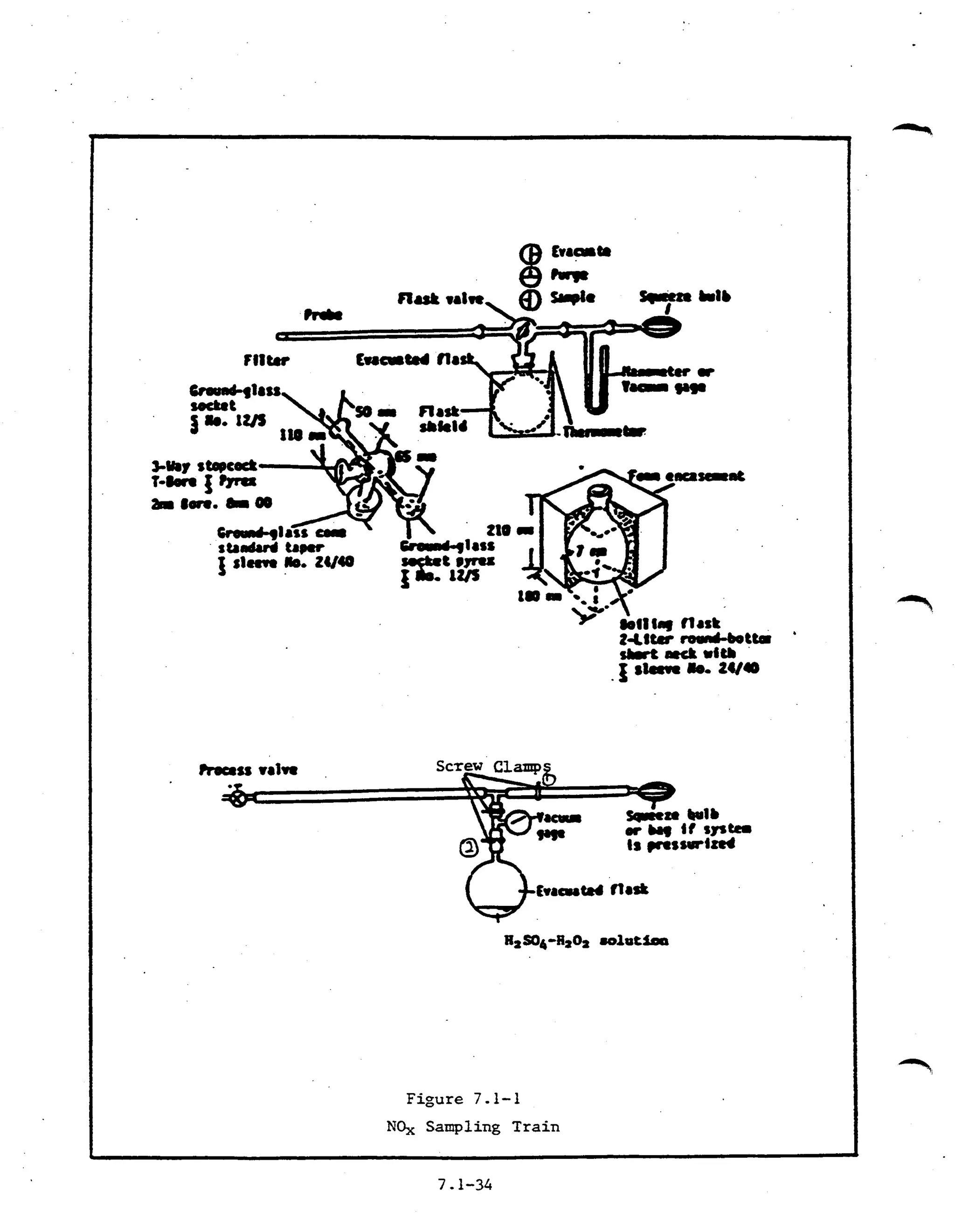


The document describes procedures for determining nitrogen oxide emissions from stationary sources, including field sampling methods, laboratory procedures, and calculations. A grab sample is collected in an evacuated flask containing an acid solution and analyzed colorimetrically or via ion chromatography to measure nitrogen oxides except nitrous oxide. Field procedures involve collecting samples using a probe and flask, while laboratory procedures specify reagents, equipment, sample recovery, and analysis steps to process the samples collected and calculate results.


