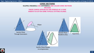
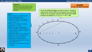
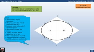
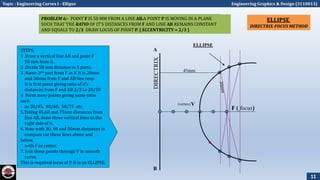
The document provides information on various methods to draw ellipses, parabolas, hyperbolas, and their tangents and normals. It defines conic sections as curves that appear when a cone is cut by a plane and discusses several geometric construction techniques. These include the concentric circle, rectangle, oblong, arcs of circles, and rhombus methods for drawing ellipses, as well as the rectangle, tangent, and directrix-focus methods for parabolas. Hyperbolas can be drawn using rectangular coordinates or the P-V diagram representation. Lastly, the document outlines how to find the tangent and normal to a conic section from a given point using properties of ellipses, parabolas and hyper
This document provides information about cycloidal curves. It defines different types of cycloidal curves that are generated when a circle rolls along a straight line or another circle without slipping. These include cycloids, epicycloids, and hypocycloids. The document outlines the classification of these curves and provides step-by-step instructions for constructing cycloids, epicycloids, and hypocycloids using compasses. It concludes with some applications of cycloidal curves in gear design, conveyors, and mechanical mechanisms.
The document discusses various types of engineering curves including conics, cycloids, involutes, spirals, and helices. It provides definitions and construction methods for different conic sections obtained from intersecting a right circular cone with cutting planes in different positions relative to the axis. Specifically, it describes how triangles, circles, ellipses, parabolas, and hyperbolas can be obtained and provides step-by-step methods for constructing ellipses using concentric circles, rectangles, oblongs, arcs of circles, and rhombuses. It also demonstrates how to construct parabolas and use directrix-focus definitions to draw ellipses, parabolas, and other curves.
The document provides instructions for drawing the perspective views of two objects:
1) A square pyramid with a base of 30mm resting on the ground plane. The station point is 70mm in front of the picture plane and 40mm to the right of the pyramid axis and 60mm above the ground.
2) A 30x20x15mm rectangular block lying on its largest face with an edge parallel to the picture plane at a 30 degree angle. The station point is 50mm in front of the picture plane and 30mm above the ground in the central plane passing through the block center.
The steps provided include understanding the reference planes, drawing lines of intersection, rays from corners to the station point, visible/
The document discusses different types of engineering curves known as conics that are formed by the intersection of a cutting plane with a cone. These conics include ellipses, parabolas, hyperbolas, circles, and triangles. The document provides definitions, examples of uses, and methods for drawing each type of conic section. It specifically describes how to construct ellipses, parabolas, and hyperbolas using different geometric techniques such as the arc of a circle, concentric circles, directrix-focus, and rectangular methods.
Engineering drawing unit test soln sandes sigdelsigdelsandes
The document provides instructions for proportional division of a straight line and drawing common tangents to two circles using different methods. It also provides steps to draw various curves like ellipses, involutes, cycloids and helixes. Instructions are given on developments of various solids like prisms, pyramids, cones and truncated cones. Dimensioned drawings are included with clear labeling to illustrate each concept.
The document discusses the objectives, outcomes, syllabus, and references for the Engineering Graphics course 20MEGO1. The objectives are to impart knowledge of engineering drawings and enable communication through graphical representations. The outcomes include the ability to interpret and construct geometric entities, orthographic projections, and develop surfaces of solids. The syllabus covers topics like curve constructions, orthographic projections, sectioning of solids, isometric and perspective projections. References provided are engineering drawing textbooks.
The document discusses the syllabus for the course 20MEGO1 - Engineering Graphics. Module 1 covers curve constructions, orthographic projection principles, and drawing multiple views of objects. Specific topics include constructing conic sections, cycloids, and involutes; principles of orthographic projection; and projecting engineering components using first angle projection. Examples are provided for constructing a cycloid traced by a rolling circle, drawing the involute of a square and circle, and obtaining front and top views of objects.
The document provides information on isometric and perspective projections in engineering graphics. It defines isometric projection as a type of pictorial projection that shows the actual sizes of all three dimensions of a solid in a single view. It also defines perspective projection as representing how an object would appear to the eye from a fixed position. The document then discusses principles, scales, views and methods of isometric projection. It provides examples of isometric views of basic geometrical shapes. It also discusses the principles and methods of perspective projection like visual ray and vanishing point methods.
This document contains the syllabus for an engineering graphics course. It covers curve constructions including conics, cycloids, and involutes. It also covers orthographic projection principles and projecting engineering components and objects from pictorial views to multiple views using first angle projection. Examples are provided on constructing a cycloid traced by a point on a rolling circle, drawing the involute of a square and circle, and projecting views of objects.
engineering curves .
Definition of Engineering Curves
Definition of Engineering Curves – When a cone is cut by a cutting plane with different positions of the plane relative to the axis of cone, it gives various types of curves like Triangle, Circle, ellipse, parabola, and hyperbola. These curves are known as conic sections.
* Vertical white line shows axis of cone in above image.
** Green lines shows different positions of cutting planes
Different methods to have types of conic sections on a cone we need to cut a cone as per following:
To get Triangle:
We have to cut cone from apex to centre of the base (vertically)
To get Circle:
We have to cut cone by a cutting plan which should parallel to base or perpendicular to axis of cone.
To get Ellipse:
We have to cut cone in such a way that the cutting plane remains inclined to axis of cone and it cuts all generators of cone.
To get Parabola:
We have to cut a cone by a cutting plane which should inclined to axis of cone but remains parallel to one of the generators of cone.
To get Hyperbola:
We have to cut a cone by cutting plane which should parallel to axis of cone.
This document provides steps to draw a hypocycloid curve, and find the tangent and normal to the curve at a given point. It involves using a rolling circle of diameter 60mm inside a directing circle of diameter 160mm. The hypocycloid is drawn by connecting the points traced by the center of the rolling circle as it revolves around the directing circle. Then, for a given point 40mm from the center of the directing circle, arcs are drawn to find the tangent and normal lines.
1. This module discusses the projection of sectioned solids and development of surfaces. It covers sectioning solids when the cutting plane is inclined to one principal plane and perpendicular to the other.
2. The development of lateral surfaces is covered for simple solids like prisms, pyramids, cylinders and cones, as well as solids with cut-outs and holes.
3. Examples are provided to illustrate obtaining the true shape of sections and developing the lateral surfaces of various solids through exercises.
A cycloid is a curve traced by a point on the circumference of a rolling circle. It is generated when a circle rolls along a straight line without slipping. An epicycloid is formed when the generating circle rolls along the outside of another directing circle, while a hypotrochoid is formed when it rolls on the inside. These curves are constructed by marking positions of the generating circle as it rolls and joining the traced points. Cycloids find applications in gear designs, conveyors, and the study of rolling motions in mechanisms.
This document provides information about isometric drawings and projections. It begins by explaining that 3D drawings can be drawn in various ways, including isometrically where the three axes are equally inclined at 120 degrees. It then discusses the construction of isometric scales and various techniques for drawing isometric views of plane figures, solids, and assemblies of objects. Examples are provided to illustrate how to draw isometric views when given orthographic projections of an object. The purpose of isometric drawings is to show the overall size, shape, and appearance of an object prior to production.
Isometric projection is a method of visually representing three-dimensional objects in two dimensions at a set of fixed angles. Specifically, the three axes are shown equally foreshortened at 120 degree angles to each other. This projection technique is commonly used in technical drawings and video game graphics to depict 3D environments. While it maintains object measurements, isometric projection distorts perspective in a way that can make depth perception difficult. As such, it fell out of favor for 3D graphics but saw renewed use in indie video games.
This document discusses orthographic projection and provides examples of drawing orthographic views from isometric views using first and third angle projection methods. It includes an isometric view of an object with its corresponding front, top, and right side orthographic views drawn to scale with dimensions. The document also provides step-by-step instructions for drawing orthographic projections of additional example objects from their isometric views using different projection methods.
The document discusses using GeoGebra to construct and investigate the properties of various geometric figures. Students will work in pairs using GeoGebra to construct shapes like rectangles, squares, triangles, parallelograms, and rhombuses. They will explore the defining properties of each figure and use a "drag test" to determine if their construction is accurate or just a drawing. The goal is for students to better understand geometric shapes and constructions through an interactive activity using dynamic geometry software.
This document provides instructions for performing various geometric constructions. It begins with an introduction on the importance of geometric constructions in engineering drawing. It then covers techniques for constructing lines, angles, triangles, circles, quadrilaterals, regular polygons, tangents to circles, joining circles, ellipses, and involutes. The document provides detailed step-by-step instructions for over 30 different geometric constructions, with diagrams to illustrate each method. Accuracy is emphasized as the main difficulty in geometric constructions.
This document discusses different methods of pictorial projection, including isometric and oblique projection. It provides details on how to construct and draw various geometric shapes and objects using these projection methods. Specifically, it describes rules for isometric projection, types of oblique projection, and several techniques for drawing circles and curves in both isometric and oblique views, such as the American method, ordinate method, and diagonal method. Examples are given for how to construct isometric drawings of solid cylinders, hollow cylinders, and step shafts using these circle construction techniques.
The document provides instructions for drawing 13 isometric views of differently shaped blocks. For each block, three orthographic views are shown in figures 1 through 13 and directions are given to draw a full size isometric view of the block in the direction of the arrows shown, with a grid size of 10 mm x 10 mm and without showing hidden details.
Isometric view of combination of solids: Cylinder resting centrally over Squa...SUBIN B MARKOSE
The document provides 13 step-by-step instructions for drawing the isometric view of a cylinder resting on a square block. It first instructs the reader to draw the front and top views of the combination. It then explains how to plot points on the isometric axes and draw lines to form the box shape of the square block. Following this, it details how to enclose the circular base of the cylinder within a box and project points onto the isometric axes to form an elliptical shape. Finally, it demonstrates how to draw a second elliptical shape for the top of the cylinder and join the two ellipses to show the full isometric view of the cylinder on the block.
This document provides information and examples regarding isometric projection drawings. It defines key terms like isometric axes, lines, and planes. It explains that in isometric projection, all three dimensions are shown in one view at equal 120 degree angles between axes. It provides instructions for constructing isometric scales and converting true lengths to reduced isometric lengths. It includes examples of how to draw isometric views of various objects like prisms, pyramids, cylinders, and spherical objects. It also provides practice problems drawing isometric views given orthographic projections as input.
This document contains a presentation by Prof. Vinay V. Ankolekar on engineering curves and conic sections. It discusses ellipses, parabolas, hyperbolas and how they are formed by cutting a cone with different planes. Various methods for constructing these curves like directrix-focus, rectangle, and tangent methods are presented. Applications of these conic sections in areas like bridges, pipes, gears and projectile motion are also described. Several problems demonstrating the construction of these curves using different techniques are shown.
Here are the steps to solve this problem:
1. The diameter of the directing circle is 150 mm. So its radius (R) is 150/2 = 75 mm.
2. The radius of the rolling circle (r) is 25 mm.
3. We are required to draw the locus of the point P which lies on the circumference of the rolling circle.
4. Since the rolling circle rolls outside the directing circle, the curve traced is an epicycloid.
5. To draw an epicycloid, we use the formula:
Arc of epicycloid = Rd * Θ
Where, Rd is the radius of the directing circle and Θ is the central angle swept in one
Engineering drawing practice questions first semester - 2019-2020 (1)AuduJoshua1
This document contains practice questions for an engineering drawing course. It covers topics like the advantages of engineering drawings over verbal descriptions, different types of drawing lines, scales, dimensions, geometric constructions, orthographic projections, and multi-view drawings. The questions range from defining key terms to practical exercises like constructing geometric shapes, dividing lines to given ratios, and developing views of objects. The goal is to test and strengthen students' understanding of core concepts in engineering graphics and technical drawing.
The document describes various engineering curves including conic sections like ellipses, parabolas, and hyperbolas. It provides different methods for constructing these curves, such as the concentric circle method, rectangle method, and directrix-focus method. It also discusses drawing tangents and normals to the curves. Other curves covered include involutes, cycloids, trochoids, spirals, and helices. The document contains examples demonstrating how to apply these construction techniques to draw the curves based on given parameters.
The document discusses various engineering curves including conic sections like ellipses, parabolas and hyperbolas. It provides definitions and methods of constructing these curves. Specifically, it outlines six methods of constructing ellipses including the concentric circle, rectangle, oblong, arcs of circle, rhombus and directrix-focus methods. It also describes three methods of constructing parabolas and hyperbolas including the rectangle method, method of tangents and directrix-focus method. Additionally, it discusses drawing tangents and normals to these curves.
This document provides an overview of the contents of an engineering graphics course. It includes 17 sections covering topics like scales, engineering curves, orthographic projections, sections and developments, and isometric projections. For each section, it lists the subtopics that will be covered and provides example problems to solve. The document aims to introduce students to the key concepts and problem-solving techniques in engineering graphics.
The document discusses various methods of drawing conic sections such as ellipses, parabolas, and hyperbolas. It provides details on the concentric circle method, rectangle method, oblong method, arcs of circle method, and general locus method for drawing ellipses. For parabolas, it describes the rectangle method, tangent method, and basic locus method. The hyperbola can be drawn using the rectangular hyperbola method, basic locus method, and through a given point with its coordinates. The document also discusses how to draw tangents and normals to these conic section curves from a given point.
The document provides information about engineering curves and their classification. It discusses that engineering curves are useful in nature, representing laws of nature on graphs. They are useful in engineering for understanding laws, manufacturing, design, analysis of forces, and construction. It then classifies key engineering curves like conics, cycloids, involutes, spirals, and helices. The document further explains different types of conics like circles, ellipses, parabolas, hyperbolas obtained from the intersection of a cutting plane with a right circular cone at different angles. It provides definitions and properties of each conic section. Finally, it discusses different methods to draw ellipses and parabolas like arc of circles, concentric circles, rectangle
This document provides information on various types of engineering curves including conic curves, spirals, cycloids and involutes. It discusses the different methods for drawing ellipses including the concentric circle, rectangular, oblong, arc of circle and rhombus methods. The document also covers drawing parabolas using the rectangle, tangent and directrix-focus methods. Additionally, it demonstrates how to draw a hyperbola through a given point and construct tangents and normals to ellipses and hyperbolas at a specified point.
This document provides methods for drawing three common conic sections (curves): ellipses, parabolas, and hyperbolas. It outlines six different methods for constructing ellipses, including the concentric circle, rectangle, oblong, arcs of circles, rhombus, and directrix-focus methods. Two methods are described for drawing parabolas: the rectangle method and method of tangents. And three examples are given for hyperbolas: the rectangular hyperbola using coordinates, the P-V diagram, and the directrix-focus method. The document also explains how to draw tangents and normals to these curves from a given point.
CURVE 1- THIS SLIDE CONTAINS WHOLE SYLLABUS OF ENGINEERING DRAWING/GRAPHICS. IT IS THE MOST SIMPLE AND INTERACTIVE WAY TO LEARN ENGINEERING DRAWING.SYLLABUS IS RELATED TO rajiv gandhi proudyogiki vishwavidyalaya / rajiv gandhi TECHNICAL UNIVERSITY ,BHOPAL.
This document provides information on engineering curves and conic sections. It describes different methods for drawing ellipses, parabolas, and hyperbolas including the concentric circle method, rectangle method, oblong method, and arcs of circle method. It also discusses drawing tangents and normals to these curves. Conic sections such as ellipses, parabolas, and hyperbolas are formed by cutting a cone with different plane sections. The ratio of a point's distances from a fixed point and fixed line is used to define eccentricity for these curves.
This document provides methods for drawing three common conic sections (ellipses, parabolas, and hyperbolas). It outlines six methods for drawing ellipses using concentric circles, rectangles, oblongs, arcs of circles, rhombi, and the directrix-focus definition. Two methods are given for drawing parabolas using rectangles and the directrix-focus definition. Hyperbolas can be drawn using rectangular hyperbolas based on coordinates or P-V diagrams, and the directrix-focus definition. The document also demonstrates how to draw tangents and normals to these curves from a given point using properties of their geometric definitions.
This document provides methods for drawing three common conic sections - ellipses, parabolas, and hyperbolas. It outlines six methods for drawing ellipses, including the concentric circle method, rectangle method, and directrix-focus method. Two methods are described for drawing parabolas: the rectangle method and directrix-focus method. Three hyperbola problems are also shown, demonstrating the rectangular hyperbola, P-V diagram, and directrix-focus definition. Examples are given for each conic section with step-by-step instructions to draw the curves using the different techniques.
This document provides methods for drawing three common conic sections (ellipses, parabolas, and hyperbolas). It outlines six methods for drawing ellipses using concentric circles, rectangles, oblongs, arcs of circles, rhombi, and the directrix-focus definition. Two methods are given for drawing parabolas using rectangles and the directrix-focus definition. Hyperbolas can be drawn using rectangular hyperbolas based on coordinates or P-V diagrams, and the directrix-focus definition. The document also demonstrates how to draw tangents and normals to these curves from a given point using properties of their geometric definitions.
This document contains information about the Engineering Graphics course for the Department of Mechanical Engineering at Narsimha Reddy Engineering College. It includes the course code, syllabus units covering topics like orthographic projections, sections, isometric projections, and AutoCAD basics. It also provides sample practice sheets on lettering, dimensions, conic sections, cycloids, epicycloids, hypocycloids, and involutes that include instructions, examples to practice, and assignments. The document specifies the textbook and reference books for the course.
engineering curves :Engineering curves are fundamental shapes used in design, analysis, and visualization across various engineering fields. They include conic sections, polynomials, splines, Bezier curves, and NURBS. Represented by explicit, parametric, or implicit equations, they possess properties like curvature and tangents. Engineers use them in CAD, graphics, motion planning, curve fitting, and manufacturing for tasks like interpolation and approximation. Understanding these curves is vital for effective engineering design and problem-solving.
The document provides information on constructing conic sections like ellipses, parabolas, and hyperbolas using the eccentricity method. It gives step-by-step procedures to draw the curves based on the distance between the focus and directrix and the eccentricity. It also describes how to draw tangents and normals to these curves at any given point. Examples are included to practice constructing each type of conic section based on given parameters.
This document provides definitions and examples of common engineering curves including involutes, cycloids, spirals, and helices. It begins by listing different types of involutes defined by the string length relative to the circle's circumference. Definitions are then given for cycloids based on whether the rolling circle is inside or outside the directing circle. Superior and inferior trochoids are distinguished based on this as well. Spirals are defined as curves generated by a point revolving around a fixed point while also moving toward it. Helices are curves generated by a point moving around a cylinder or cone surface while advancing axially. Examples are provided for drawing various curves along with methods for constructing tangents and normals.
DEEP LEARNING FOR SMART GRID INTRUSION DETECTION: A HYBRID CNN-LSTM-BASED MODELijaia
As digital technology becomes more deeply embedded in power systems, protecting the communication
networks of Smart Grids (SG) has emerged as a critical concern. Distributed Network Protocol 3 (DNP3)
represents a multi-tiered application layer protocol extensively utilized in Supervisory Control and Data
Acquisition (SCADA)-based smart grids to facilitate real-time data gathering and control functionalities.
Robust Intrusion Detection Systems (IDS) are necessary for early threat detection and mitigation because
of the interconnection of these networks, which makes them vulnerable to a variety of cyberattacks. To
solve this issue, this paper develops a hybrid Deep Learning (DL) model specifically designed for intrusion
detection in smart grids. The proposed approach is a combination of the Convolutional Neural Network
(CNN) and the Long-Short-Term Memory algorithms (LSTM). We employed a recent intrusion detection
dataset (DNP3), which focuses on unauthorized commands and Denial of Service (DoS) cyberattacks, to
train and test our model. The results of our experiments show that our CNN-LSTM method is much better
at finding smart grid intrusions than other deep learning algorithms used for classification. In addition,
our proposed approach improves accuracy, precision, recall, and F1 score, achieving a high detection
accuracy rate of 99.50%.
Null Bangalore | Pentesters Approach to AWS IAMDivyanshu
#Abstract:
- Learn more about the real-world methods for auditing AWS IAM (Identity and Access Management) as a pentester. So let us proceed with a brief discussion of IAM as well as some typical misconfigurations and their potential exploits in order to reinforce the understanding of IAM security best practices.
- Gain actionable insights into AWS IAM policies and roles, using hands on approach.
#Prerequisites:
- Basic understanding of AWS services and architecture
- Familiarity with cloud security concepts
- Experience using the AWS Management Console or AWS CLI.
- For hands on lab create account on [killercoda.com](https://killercoda.com/cloudsecurity-scenario/)
# Scenario Covered:
- Basics of IAM in AWS
- Implementing IAM Policies with Least Privilege to Manage S3 Bucket
- Objective: Create an S3 bucket with least privilege IAM policy and validate access.
- Steps:
- Create S3 bucket.
- Attach least privilege policy to IAM user.
- Validate access.
- Exploiting IAM PassRole Misconfiguration
-Allows a user to pass a specific IAM role to an AWS service (ec2), typically used for service access delegation. Then exploit PassRole Misconfiguration granting unauthorized access to sensitive resources.
- Objective: Demonstrate how a PassRole misconfiguration can grant unauthorized access.
- Steps:
- Allow user to pass IAM role to EC2.
- Exploit misconfiguration for unauthorized access.
- Access sensitive resources.
- Exploiting IAM AssumeRole Misconfiguration with Overly Permissive Role
- An overly permissive IAM role configuration can lead to privilege escalation by creating a role with administrative privileges and allow a user to assume this role.
- Objective: Show how overly permissive IAM roles can lead to privilege escalation.
- Steps:
- Create role with administrative privileges.
- Allow user to assume the role.
- Perform administrative actions.
- Differentiation between PassRole vs AssumeRole
Try at [killercoda.com](https://killercoda.com/cloudsecurity-scenario/)
Digital Twins Computer Networking Paper Presentation.pptxaryanpankaj78
A Digital Twin in computer networking is a virtual representation of a physical network, used to simulate, analyze, and optimize network performance and reliability. It leverages real-time data to enhance network management, predict issues, and improve decision-making processes.
Build the Next Generation of Apps with the Einstein 1 Platform.
Rejoignez Philippe Ozil pour une session de workshops qui vous guidera à travers les détails de la plateforme Einstein 1, l'importance des données pour la création d'applications d'intelligence artificielle et les différents outils et technologies que Salesforce propose pour vous apporter tous les bénéfices de l'IA.
VARIABLE FREQUENCY DRIVE. VFDs are widely used in industrial applications for...PIMR BHOPAL
Variable frequency drive .A Variable Frequency Drive (VFD) is an electronic device used to control the speed and torque of an electric motor by varying the frequency and voltage of its power supply. VFDs are widely used in industrial applications for motor control, providing significant energy savings and precise motor operation.
Applications of artificial Intelligence in Mechanical Engineering.pdfAtif Razi
Historically, mechanical engineering has relied heavily on human expertise and empirical methods to solve complex problems. With the introduction of computer-aided design (CAD) and finite element analysis (FEA), the field took its first steps towards digitization. These tools allowed engineers to simulate and analyze mechanical systems with greater accuracy and efficiency. However, the sheer volume of data generated by modern engineering systems and the increasing complexity of these systems have necessitated more advanced analytical tools, paving the way for AI.
AI offers the capability to process vast amounts of data, identify patterns, and make predictions with a level of speed and accuracy unattainable by traditional methods. This has profound implications for mechanical engineering, enabling more efficient design processes, predictive maintenance strategies, and optimized manufacturing operations. AI-driven tools can learn from historical data, adapt to new information, and continuously improve their performance, making them invaluable in tackling the multifaceted challenges of modern mechanical engineering.
Design and optimization of ion propulsion dronebjmsejournal
Electric propulsion technology is widely used in many kinds of vehicles in recent years, and aircrafts are no exception. Technically, UAVs are electrically propelled but tend to produce a significant amount of noise and vibrations. Ion propulsion technology for drones is a potential solution to this problem. Ion propulsion technology is proven to be feasible in the earth’s atmosphere. The study presented in this article shows the design of EHD thrusters and power supply for ion propulsion drones along with performance optimization of high-voltage power supply for endurance in earth’s atmosphere.
Gas agency management system project report.pdfKamal Acharya
The project entitled "Gas Agency" is done to make the manual process easier by making it a computerized system for billing and maintaining stock. The Gas Agencies get the order request through phone calls or by personal from their customers and deliver the gas cylinders to their address based on their demand and previous delivery date. This process is made computerized and the customer's name, address and stock details are stored in a database. Based on this the billing for a customer is made simple and easier, since a customer order for gas can be accepted only after completing a certain period from the previous delivery. This can be calculated and billed easily through this. There are two types of delivery like domestic purpose use delivery and commercial purpose use delivery. The bill rate and capacity differs for both. This can be easily maintained and charged accordingly.
Redefining brain tumor segmentation: a cutting-edge convolutional neural netw...IJECEIAES
Medical image analysis has witnessed significant advancements with deep learning techniques. In the domain of brain tumor segmentation, the ability to
precisely delineate tumor boundaries from magnetic resonance imaging (MRI)
scans holds profound implications for diagnosis. This study presents an ensemble convolutional neural network (CNN) with transfer learning, integrating
the state-of-the-art Deeplabv3+ architecture with the ResNet18 backbone. The
model is rigorously trained and evaluated, exhibiting remarkable performance
metrics, including an impressive global accuracy of 99.286%, a high-class accuracy of 82.191%, a mean intersection over union (IoU) of 79.900%, a weighted
IoU of 98.620%, and a Boundary F1 (BF) score of 83.303%. Notably, a detailed comparative analysis with existing methods showcases the superiority of
our proposed model. These findings underscore the model’s competence in precise brain tumor localization, underscoring its potential to revolutionize medical
image analysis and enhance healthcare outcomes. This research paves the way
for future exploration and optimization of advanced CNN models in medical
imaging, emphasizing addressing false positives and resource efficiency.
2. Topic : Engineering Curves I - Ellipse Engineering Graphics & Design (3110013)
Content
ELLIPSE:
1.Concentric Circle Method
2.Rectangle Method
3.Oblong Method
4.Arcs of Circle Method
5.Rhombus Method
6.Basic Locus Method (Directrix – focus)
2
3. Topic : Engineering Curves I - Ellipse Engineering Graphics & Design (3110013)
ENGINEERING CURVES
Part- I {Conic Sections}
ELLIPSE
1.Concentric Circle Method
2.Rectangle Method
3.Oblong Method
4.Arcs of Circle Method
5.Rhombus Method
6.Basic Locus Method
(Directrix – focus)
HYPERBOLA
1.Rectangular Hyperbola
(coordinates given)
2 Rectangular Hyperbola
(P-V diagram - Equation given)
3.Basic Locus Method
(Directrix – focus)
PARABOLA
1.Rectangle Method
2 Method of Tangents
( Triangle Method)
3.Basic Locus Method
(Directrix – focus)
3
4. Topic : Engineering Curves I - Ellipse Engineering Graphics & Design (3110013)
CONIC SECTIONS
ELLIPSE, PARABOLA AND HYPERBOLA ARE CALLED CONIC SECTIONS
BECAUSE
THESE CURVES APPEAR ON THE SURFACE OF A CONE
WHEN IT IS CUT BY SOME TYPICAL CUTTING PLANES.
Section Plane
Through Generators
Ellipse
Section Plane Parallel
to end generator.
Section Plane
Parallel to Axis.
Hyperbola
4
5. Topic : Engineering Curves I - Ellipse Engineering Graphics & Design (3110013)
These are the loci of points moving in a plane such that the ratio of it’s distances
from a fixed point And a fixed line always remains constant.
The Ratio is called ECCENTRICITY. (E)
A) For Ellipse E<1
B) For Parabola E=1
C) For Hyperbola E>1
SECOND DEFINATION OF AN ELLIPSE:-
It is a locus of a point moving in a plane
such that the SUM of it’s distances from TWO fixed points
always remains constant.
{And this sum equals to the length of major axis.}
These TWO fixed points are FOCUS 1 & FOCUS 2
Refer Problem nos. 6. 9 & 12
Refer Problem no.4
Ellipse by Arcs of Circles Method.
COMMON DEFINATION OF ELLIPSE, PARABOLA & HYPERBOLA:
5
6. Topic : Engineering Curves I - Ellipse Engineering Graphics & Design (3110013)
1
2
3
4
5
6
7
8
9
10
BA
D
C
1
2
3
4
5
6
7
8
9
10
Steps:
1. Draw both axes as perpendicular
bisectors of each other & name their ends
as shown.
2. Taking their intersecting point as a
center, draw two concentric circles
considering both as respective diameters.
3. Divide both circles in 12 equal parts &
name as shown.
4. From all points of outer circle draw
vertical lines downwards and upwards
respectively.
5.From all points of inner circle draw
horizontal lines to intersect those vertical
lines.
6. Mark all intersecting points properly as
those are the points on ellipse.
7. Join all these points along with the ends
of both axes in smooth possible curve. It is
required ellipse.
Problem 1 :-
Draw ellipse by concentric circle method.
Take major axis 100 mm and minor axis 70 mm long.
ELLIPSE
BY CONCENTRIC CIRCLE METHOD
6
7. Topic : Engineering Curves I - Ellipse Engineering Graphics & Design (3110013)
1
2
3
4
1
2
3
4
A B
C
D
Problem 2
Draw ellipse by Rectangle method.
Take major axis 100 mm and minor axis 70 mm long.
Steps:
1 Draw a rectangle taking major and
minor axes as sides.
2. In this rectangle draw both axes as
perpendicular bisectors of each
other..
3. For construction, select upper left
part of rectangle. Divide vertical
small side and horizontal long side
into same number of equal parts.(
here divided in four parts)
4. Name those as shown..
5. Now join all vertical points 1,2,3,4,
to the upper end of minor axis. And
all horizontal points i.e.1,2,3,4 to the
lower end of minor axis.
6. Then extend C-1 line upto D-1 and
mark that point. Similarly extend C-2,
C-3, C-4 lines up to D-2, D-3, & D-4
lines.
7. Mark all these points properly and
join all along with ends A and D in
smooth possible curve. Do similar
construction in right side part. along
with lower half of the rectangle.
Join all points in smooth curve.
It is required ellipse.
ELLIPSE
BY RECTANGLE METHOD
7
8. Topic : Engineering Curves I - Ellipse Engineering Graphics & Design (3110013)
1
2
3
4
A B
1
2
3
4
Problem 3:-
Draw ellipse by Oblong method.
Draw a parallelogram of 100 mm and 70 mm long sides
with included angle of 750.Inscribe Ellipse in it.
STEPS ARE SIMILAR TO
THE PREVIOUS CASE
(RECTANGLE METHOD)
ONLY IN PLACE OF RECTANGLE,
HERE IS A PARALLELOGRAM.
ELLIPSE
BY OBLONG METHOD
8
9. Topic : Engineering Curves I - Ellipse Engineering Graphics & Design (3110013)
F1 F21 2 3 4
A B
C
D
p1
p2
p3
p4
ELLIPSE
BY ARCS OF CIRCLE METHOD
O
PROBLEM 4.
MAJOR AXIS AB & MINOR AXIS CD ARE
100 AMD 70MM LONG RESPECTIVELY
.DRAW ELLIPSE BY ARCS OF CIRLES
METHOD.
STEPS:
1.Draw both axes as usual.Name the
ends & intersecting point
2.Taking AO distance I.e.half major
axis, from C, mark F1 & F2 On AB .
( focus 1 and 2.)
3.On line F1- O taking any distance,
mark points 1,2,3, & 4
4.Taking F1 center, with distance A-1
draw an arc above AB and taking F2
center, with B-1 distance cut this arc.
Name the point p1
5.Repeat this step with same centers but
taking now A-2 & B-2 distances for
drawing arcs. Name the point p2
6.Similarly get all other P points.
With same steps positions of P can be
located below AB.
7.Join all points by smooth curve to get
an ellipse/
As per the definition Ellipse is locus of point P moving in
a plane such that the SUM of it’s distances from two fixed
points (F1 & F2) remains constant and equals to the length
of major axis AB.(Note A .1+ B .1=A . 2 + B. 2 = AB)
9
10. Topic : Engineering Curves I - Ellipse Engineering Graphics & Design (3110013)
1
4
2
3
A B
D C
ELLIPSE
BY RHOMBUS METHODPROBLEM 5.
DRAW RHOMBUS OF 100 MM & 70 MM LONG
DIAGONALS AND INSCRIBE AN ELLIPSE IN IT.
STEPS:
1. Draw rhombus of given
dimensions.
2. Mark mid points of all sides &
name Those A,B,C,& D
3. Join these points to the ends of
smaller diagonals.
4. Mark points 1,2,3,4 as four
centers.
5. Taking 1 as center and 1-A
radius draw an arc AB.
6. Take 2 as center draw an arc CD.
7. Similarly taking 3 & 4 as centers
and 3-D radius draw arcs DA & BC.
10
11. Topic : Engineering Curves I - Ellipse Engineering Graphics & Design (3110013)
ELLIPSE
DIRECTRIX-FOCUS METHOD
PROBLEM 6:- POINT F IS 50 MM FROM A LINE AB.A POINT P IS MOVING IN A PLANE
SUCH THAT THE RATIO OF IT’S DISTANCES FROM F AND LINE AB REMAINS CONSTANT
AND EQUALS TO 2/3 DRAW LOCUS OF POINT P. { ECCENTRICITY = 2/3 }
F ( focus)
V
ELLIPSE
(vertex)
A
B
STEPS:
1 .Draw a vertical line AB and point F
50 mm from it.
2 .Divide 50 mm distance in 5 parts.
3 .Name 2nd part from F as V. It is 20mm
and 30mm from F and AB line resp.
It is first point giving ratio of it’s
distances from F and AB 2/3 i.e 20/30
4 Form more points giving same ratio
such
as 30/45, 40/60, 50/75 etc.
5.Taking 45,60 and 75mm distances from
line AB, draw three vertical lines to the
right side of it.
6. Now with 30, 40 and 50mm distances in
compass cut these lines above and
below,
with F as center.
7. Join these points through V in smooth
curve.
This is required locus of P. It is an ELLIPSE.
45mm
11