engineering curves .
Definition of Engineering Curves
Definition of Engineering Curves – When a cone is cut by a cutting plane with different positions of the plane relative to the axis of cone, it gives various types of curves like Triangle, Circle, ellipse, parabola, and hyperbola. These curves are known as conic sections.
* Vertical white line shows axis of cone in above image.
** Green lines shows different positions of cutting planes
Different methods to have types of conic sections on a cone we need to cut a cone as per following:
To get Triangle:
We have to cut cone from apex to centre of the base (vertically)
To get Circle:
We have to cut cone by a cutting plan which should parallel to base or perpendicular to axis of cone.
To get Ellipse:
We have to cut cone in such a way that the cutting plane remains inclined to axis of cone and it cuts all generators of cone.
To get Parabola:
We have to cut a cone by a cutting plane which should inclined to axis of cone but remains parallel to one of the generators of cone.
To get Hyperbola:
We have to cut a cone by cutting plane which should parallel to axis of cone.
Curves2- THIS SLIDE CONTAINS WHOLE SYLLABUS OF ENGINEERING DRAWING/GRAPHICS. IT IS THE MOST SIMPLE AND INTERACTIVE WAY TO LEARN ENGINEERING DRAWING.SYLLABUS IS RELATED TO rajiv gandhi proudyogiki vishwavidyalaya / rajiv gandhi TECHNICAL UNIVERSITY ,BHOPAL.
Isometric
THIS SLIDE CONTAINS WHOLE SYLLABUS OF ENGINEERING DRAWING/GRAPHICS. IT IS THE MOST SIMPLE AND INTERACTIVE WAY TO LEARN ENGINEERING DRAWING.SYLLABUS IS RELATED TO rajiv gandhi proudyogiki vishwavidyalaya / rajiv gandhi TECHNICAL UNIVERSITY ,BHOPAL.
CURVE 1- THIS SLIDE CONTAINS WHOLE SYLLABUS OF ENGINEERING DRAWING/GRAPHICS. IT IS THE MOST SIMPLE AND INTERACTIVE WAY TO LEARN ENGINEERING DRAWING.SYLLABUS IS RELATED TO rajiv gandhi proudyogiki vishwavidyalaya / rajiv gandhi TECHNICAL UNIVERSITY ,BHOPAL.
Download the original presentation for animation and clear understanding. This Presentation describes the concepts of Engineering Drawing of VTU Syllabus. However same can also be used for learning drawing concepts. Please write to me for suggestions and criticisms here: hareeshang@gmail.com or visit this website for more details: www.hareeshang.wikifoundry.com.
engineering curves :Engineering curves are fundamental shapes used in design, analysis, and visualization across various engineering fields. They include conic sections, polynomials, splines, Bezier curves, and NURBS. Represented by explicit, parametric, or implicit equations, they possess properties like curvature and tangents. Engineers use them in CAD, graphics, motion planning, curve fitting, and manufacturing for tasks like interpolation and approximation. Understanding these curves is vital for effective engineering design and problem-solving.
Embracing GenAI - A Strategic ImperativePeter Windle
Artificial Intelligence (AI) technologies such as Generative AI, Image Generators and Large Language Models have had a dramatic impact on teaching, learning and assessment over the past 18 months. The most immediate threat AI posed was to Academic Integrity with Higher Education Institutes (HEIs) focusing their efforts on combating the use of GenAI in assessment. Guidelines were developed for staff and students, policies put in place too. Innovative educators have forged paths in the use of Generative AI for teaching, learning and assessments leading to pockets of transformation springing up across HEIs, often with little or no top-down guidance, support or direction.
This Gasta posits a strategic approach to integrating AI into HEIs to prepare staff, students and the curriculum for an evolving world and workplace. We will highlight the advantages of working with these technologies beyond the realm of teaching, learning and assessment by considering prompt engineering skills, industry impact, curriculum changes, and the need for staff upskilling. In contrast, not engaging strategically with Generative AI poses risks, including falling behind peers, missed opportunities and failing to ensure our graduates remain employable. The rapid evolution of AI technologies necessitates a proactive and strategic approach if we are to remain relevant.
Operation “Blue Star” is the only event in the history of Independent India where the state went into war with its own people. Even after about 40 years it is not clear if it was culmination of states anger over people of the region, a political game of power or start of dictatorial chapter in the democratic setup.
The people of Punjab felt alienated from main stream due to denial of their just demands during a long democratic struggle since independence. As it happen all over the word, it led to militant struggle with great loss of lives of military, police and civilian personnel. Killing of Indira Gandhi and massacre of innocent Sikhs in Delhi and other India cities was also associated with this movement.
A Strategic Approach: GenAI in EducationPeter Windle
Artificial Intelligence (AI) technologies such as Generative AI, Image Generators and Large Language Models have had a dramatic impact on teaching, learning and assessment over the past 18 months. The most immediate threat AI posed was to Academic Integrity with Higher Education Institutes (HEIs) focusing their efforts on combating the use of GenAI in assessment. Guidelines were developed for staff and students, policies put in place too. Innovative educators have forged paths in the use of Generative AI for teaching, learning and assessments leading to pockets of transformation springing up across HEIs, often with little or no top-down guidance, support or direction.
This Gasta posits a strategic approach to integrating AI into HEIs to prepare staff, students and the curriculum for an evolving world and workplace. We will highlight the advantages of working with these technologies beyond the realm of teaching, learning and assessment by considering prompt engineering skills, industry impact, curriculum changes, and the need for staff upskilling. In contrast, not engaging strategically with Generative AI poses risks, including falling behind peers, missed opportunities and failing to ensure our graduates remain employable. The rapid evolution of AI technologies necessitates a proactive and strategic approach if we are to remain relevant.
Palestine last event orientationfvgnh .pptxRaedMohamed3
An EFL lesson about the current events in Palestine. It is intended to be for intermediate students who wish to increase their listening skills through a short lesson in power point.
The French Revolution, which began in 1789, was a period of radical social and political upheaval in France. It marked the decline of absolute monarchies, the rise of secular and democratic republics, and the eventual rise of Napoleon Bonaparte. This revolutionary period is crucial in understanding the transition from feudalism to modernity in Europe.
For more information, visit-www.vavaclasses.com
Read| The latest issue of The Challenger is here! We are thrilled to announce that our school paper has qualified for the NATIONAL SCHOOLS PRESS CONFERENCE (NSPC) 2024. Thank you for your unwavering support and trust. Dive into the stories that made us stand out!
The Roman Empire A Historical Colossus.pdfkaushalkr1407
The Roman Empire, a vast and enduring power, stands as one of history's most remarkable civilizations, leaving an indelible imprint on the world. It emerged from the Roman Republic, transitioning into an imperial powerhouse under the leadership of Augustus Caesar in 27 BCE. This transformation marked the beginning of an era defined by unprecedented territorial expansion, architectural marvels, and profound cultural influence.
The empire's roots lie in the city of Rome, founded, according to legend, by Romulus in 753 BCE. Over centuries, Rome evolved from a small settlement to a formidable republic, characterized by a complex political system with elected officials and checks on power. However, internal strife, class conflicts, and military ambitions paved the way for the end of the Republic. Julius Caesar’s dictatorship and subsequent assassination in 44 BCE created a power vacuum, leading to a civil war. Octavian, later Augustus, emerged victorious, heralding the Roman Empire’s birth.
Under Augustus, the empire experienced the Pax Romana, a 200-year period of relative peace and stability. Augustus reformed the military, established efficient administrative systems, and initiated grand construction projects. The empire's borders expanded, encompassing territories from Britain to Egypt and from Spain to the Euphrates. Roman legions, renowned for their discipline and engineering prowess, secured and maintained these vast territories, building roads, fortifications, and cities that facilitated control and integration.
The Roman Empire’s society was hierarchical, with a rigid class system. At the top were the patricians, wealthy elites who held significant political power. Below them were the plebeians, free citizens with limited political influence, and the vast numbers of slaves who formed the backbone of the economy. The family unit was central, governed by the paterfamilias, the male head who held absolute authority.
Culturally, the Romans were eclectic, absorbing and adapting elements from the civilizations they encountered, particularly the Greeks. Roman art, literature, and philosophy reflected this synthesis, creating a rich cultural tapestry. Latin, the Roman language, became the lingua franca of the Western world, influencing numerous modern languages.
Roman architecture and engineering achievements were monumental. They perfected the arch, vault, and dome, constructing enduring structures like the Colosseum, Pantheon, and aqueducts. These engineering marvels not only showcased Roman ingenuity but also served practical purposes, from public entertainment to water supply.
Biological screening of herbal drugs: Introduction and Need for
Phyto-Pharmacological Screening, New Strategies for evaluating
Natural Products, In vitro evaluation techniques for Antioxidants, Antimicrobial and Anticancer drugs. In vivo evaluation techniques
for Anti-inflammatory, Antiulcer, Anticancer, Wound healing, Antidiabetic, Hepatoprotective, Cardio protective, Diuretics and
Antifertility, Toxicity studies as per OECD guidelines
Introduction to AI for Nonprofits with Tapp NetworkTechSoup
Dive into the world of AI! Experts Jon Hill and Tareq Monaur will guide you through AI's role in enhancing nonprofit websites and basic marketing strategies, making it easy to understand and apply.
Digital Tools and AI for Teaching Learning and Research
Curves1(thedirectdata[1].com)
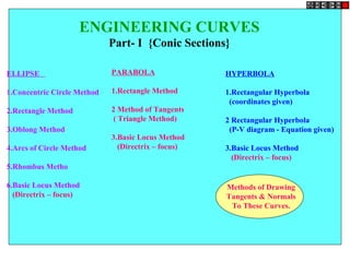
1. ENGINEERING CURVES
Part- I {Conic Sections}
ELLIPSE
1.Concentric Circle Method
2.Rectangle Method
3.Oblong Method
4.Arcs of Circle Method
5.Rhombus Metho
6.Basic Locus Method
(Directrix – focus)
HYPERBOLA
1.Rectangular Hyperbola
(coordinates given)
2 Rectangular Hyperbola
(P-V diagram - Equation given)
3.Basic Locus Method
(Directrix – focus)
PARABOLA
1.Rectangle Method
2 Method of Tangents
( Triangle Method)
3.Basic Locus Method
(Directrix – focus)
Methods of Drawing
Tangents & Normals
To These Curves.
2. CONIC SECTIONS
ELLIPSE, PARABOLA AND HYPERBOLA ARE CALLED CONIC SECTIONS
BECAUSE
THESE CURVES APPEAR ON THE SURFACE OF A CONE
WHEN IT IS CUT BY SOME TYPICAL CUTTING PLANES.
Section PlaneSection Plane
Through GeneratorsThrough Generators
EllipseEllipse
Section Plane ParallelSection Plane Parallel
to end generator.to end generator.
Parabola
Parabola
Section PlaneSection Plane
Parallel to Axis.Parallel to Axis.
HyperbolaHyperbola
OBSERVE
ILLUSTRATIONS
GIVEN BELOW..
3. These are the loci of points moving in a plane such that the ratio of it’s distances
from a fixed point And a fixed line always remains constant.
The Ratio is called ECCENTRICITY. (E)
A) For Ellipse E<1
B) For Parabola E=1
C) For Hyperbola E>1
SECOND DEFINATION OF AN ELLIPSE:-
It is a locus of a point moving in a plane
such that the SUM of it’s distances from TWO fixed points
always remains constant.
{And this sum equals to the length of major axis.}
These TWO fixed points are FOCUS 1 & FOCUS 2
Refer Problem nos. 6. 9 & 12
Refer Problem no.4
Ellipse by Arcs of Circles Method.
COMMON DEFINATION OF ELLIPSE, PARABOLA & HYPERBOLA:
4. 1
2
3
4
5
6
7
8
9
10
BA
D
C
1
2
3
4
5
6
7
8
9
10
Steps:
1. Draw both axes as perpendicular bisectors
of each other & name their ends as shown.
2. Taking their intersecting point as a center,
draw two concentric circles considering both
as respective diameters.
3. Divide both circles in 12 equal parts &
name as shown.
4. From all points of outer circle draw vertical
lines downwards and upwards respectively.
5.From all points of inner circle draw
horizontal lines to intersect those vertical
lines.
6. Mark all intersecting points properly as
those are the points on ellipse.
7. Join all these points along with the ends of
both axes in smooth possible curve. It is
required ellipse.
Problem 1 :-
Draw ellipse by concentric circle method.
Take major axis 100 mm and minor axis 70 mm long.
ELLIPSE
BY CONCENTRIC CIRCLE METHOD
5. 1
2
3
4
1 2 3 4
1
2
3
4
3 2 1A B
C
D
Problem 2
Draw ellipse by Rectangle method.
Take major axis 100 mm and minor axis 70 mm long.
Steps:
1 Draw a rectangle taking major
and minor axes as sides.
2. In this rectangle draw both
axes as perpendicular bisectors
of each other..
3. For construction, select upper
left part of rectangle. Divide
vertical small side and horizontal
long side into same number of
equal parts.( here divided in four
parts)
4. Name those as shown..
5. Now join all vertical points
1,2,3,4, to the upper end of minor
axis. And all horizontal points
i.e.1,2,3,4 to the lower end of
minor axis.
6. Then extend C-1 line upto D-1
and mark that point. Similarly
extend C-2, C-3, C-4 lines up to
D-2, D-3, & D-4 lines.
7. Mark all these points properly
and join all along with ends A
and D in smooth possible curve.
Do similar construction in right
side part.along with lower half of
the rectangle.Join all points in
smooth curve.
It is required ellipse.
ELLIPSE
BY RECTANGLE METHOD
6. C
D
1
2
3
4
1 2 3 4 3 2 1A B
1
2
3
4
Problem 3:-
Draw ellipse by Oblong method.
Draw a parallelogram of 100 mm and 70 mm long
sides with included angle of 750.
Inscribe Ellipse in it.
STEPS ARE SIMILAR TO
THE PREVIOUS CASE
(RECTANGLE METHOD)
ONLY IN PLACE OF RECTANGLE,
HERE IS A PARALLELOGRAM.
ELLIPSE
BY OBLONG METHOD
7. F1 F2
1 2 3 4
A B
C
D
p1
p2
p3
p4
ELLIPSE
BY ARCS OF CIRCLE METHOD
O
PROBLEM 4.
MAJOR AXIS AB & MINOR AXIS CD ARE
100 AMD 70MM LONG RESPECTIVELY
.DRAW ELLIPSE BY ARCS OF CIRLES
METHOD.
STEPS:
1.Draw both axes as usual.Name the
ends & intersecting point
2.Taking AO distance I.e.half major
axis, from C, mark F1 & F2 On AB .
( focus 1 and 2.)
3.On line F1- O taking any distance,
mark points 1,2,3, & 4
4.Taking F1 center, with distance A-1
draw an arc above AB and taking F2
center, with B-1 distance cut this arc.
Name the point p1
5.Repeat this step with same centers but
taking now A-2 & B-2 distances for
drawing arcs. Name the point p2
6.Similarly get all other P points.
With same steps positions of P can be
located below AB.
7.Join all points by smooth curve to get
an ellipse/
As per the definition Ellipse is locus of point P moving in
a plane such that the SUM of it’s distances from two fixed
points (F1 & F2) remains constant and equals to the length
of major axis AB.(Note A .1+ B .1=A . 2 + B. 2 = AB)
8. 1
4
2
3
A B
D C
ELLIPSE
BY RHOMBUS METHOD
PROBLEM 5.
DRAW RHOMBUS OF 100 MM & 70 MM LONG
DIAGONALS AND INSCRIBE AN ELLIPSE IN IT.
STEPS:
1. Draw rhombus of given
dimensions.
2. Mark mid points of all sides &
name Those A,B,C,& D
3. Join these points to the ends of
smaller diagonals.
4. Mark points 1,2,3,4 as four
centers.
5. Taking 1 as center and 1-A
radius draw an arc AB.
6. Take 2 as center draw an arc CD.
7. Similarly taking 3 & 4 as centers
and 3-D radius draw arcs DA & BC.
9. ELLIPSE
DIRECTRIX-FOCUS METHOD
PROBLEM 6:- POINT F IS 50 MM FROM A LINE AB.A POINT P IS MOVING IN A PLANE
SUCH THAT THE RATIO OF IT’S DISTANCES FROM F AND LINE AB REMAINS CONSTANT
AND EQUALS TO 2/3 DRAW LOCUS OF POINT P. { ECCENTRICITY = 2/3 }
F ( focus)
DIRECTRIX
V
ELLIPSE
(vertex)
A
B
STEPS:
1 .Draw a vertical line AB and point F
50 mm from it.
2 .Divide 50 mm distance in 5 parts.
3 .Name 2nd
part from F as V. It is 20mm
and 30mm from F and AB line resp.
It is first point giving ratio of it’s
distances from F and AB 2/3 i.e 20/30
4 Form more points giving same ratio such
as 30/45, 40/60, 50/75 etc.
5.Taking 45,60 and 75mm distances from
line AB, draw three vertical lines to the
right side of it.
6. Now with 30, 40 and 50mm distances in
compass cut these lines above and below,
with F as center.
7. Join these points through V in smooth
curve.
This is required locus of P.It is an ELLIPSE.
30mm
45mm
10. 1
2
3
4
5
6
1 2 3 4 5 6
1
2
3
4
5
6
5 4 3 2 1
PARABOLA
RECTANGLE METHOD
PROBLEM 7: A BALL THROWN IN AIR ATTAINS 100 M HIEGHT
AND COVERS HORIZONTAL DISTANCE 150 M ON GROUND.
Draw the path of the ball (projectile)-
STEPS:
1.Draw rectangle of above size and
divide it in two equal vertical parts
2.Consider left part for construction.
Divide height and length in equal
number of parts and name those
1,2,3,4,5& 6
3.Join vertical 1,2,3,4,5 & 6 to the
top center of rectangle
4.Similarly draw upward vertical
lines from horizontal1,2,3,4,5
And wherever these lines intersect
previously drawn inclined lines in
sequence Mark those points and
further join in smooth possible curve.
5.Repeat the construction on right side
rectangle also.Join all in sequence.
This locus is Parabola.
.
11. 7.5m
A B
Draw a parabola by tangent method given base 7.5m and axis 4.5m
4.5m
1
2
3
4
5
6
1’
2’
3’
4’
5’
6’
E
F
O
Take scale 1cm = 0.5m
4.5m
12. A
B
V
PARABOLA
(VERTEX)
F
( focus)
1 2 3 4
PARABOLA
DIRECTRIX-FOCUS METHOD
SOLUTION STEPS:
1.Locate center of line, perpendicular to
AB from point F. This will be initial
point P and also the vertex.
2.Mark 5 mm distance to its right side,
name those points 1,2,3,4 and from
those
draw lines parallel to AB.
3.Mark 5 mm distance to its left of P and
name it 1.
4.Take O-1 distance as radius and F as
center draw an arc
cutting first parallel line to AB. Name
upper point P1
and lower point P2
.
(FP1=O1)
5.Similarly repeat this process by taking
again 5mm to right and left and locate
P3
P4
.
6.Join all these points in smooth curve.
It will be the locus of P equidistance
from line AB and fixed point F.
PROBLEM 9: Point F is 50 mm from a vertical straight line AB.
Draw locus of point P, moving in a plane such that
it always remains equidistant from point F and line AB.
O
P1
P2
13. P
O
40 mm
30 mm
1
2
3
12 1 2 3
1
2
HYPERBOLA
THROUGH A POINT
OF KNOWN CO-ORDINATES
Solution Steps:
1) Extend horizontal
line from P to right side.
2) Extend vertical line
from P upward.
3) On horizontal line
from P, mark some
points taking any
distance and name them
after P-1, 2,3,4 etc.
4) Join 1-2-3-4 points
to pole O. Let them cut
part [P-B] also at 1,2,3,4
points.
5) From horizontal
1,2,3,4 draw vertical
lines downwards and
6) From vertical 1,2,3,4
points [from P-B] draw
horizontal lines.
7) Line from 1
horizontal and line from
1 vertical will meet at
P1
.Similarly mark P2
, P3
,
P4
points.
8) Repeat the procedure
by marking four points
on upward vertical line
from P and joining all
those to pole O. Name
this points P6
, P7
, P8
etc.
and join them by smooth
Problem No.10: Point P is 40 mm and 30 mm from horizontal
and vertical axes respectively.Draw Hyperbola through it.
14. VOLUME:( M3
)
PRESSURE
(Kg/cm2
)
0 1 2 3 4 5 6 7 8 9 10
1
2
3
4
5
6
7
8
9
10
HYPERBOLA
P-V DIAGRAM
Problem no.11: A sample of gas is expanded in a cylinder
from 10 unit pressure to 1 unit pressure.Expansion follows
law PV=Constant.If initial volume being 1 unit, draw the
curve of expansion. Also Name the curve.
Form a table giving few more values of P & V
P V = C
+
10
5
4
2.5
2
1
1
2
2.5
4
5
10
10
10
10
10
10
10
++++++
=
=
=
=
=
=
Now draw a Graph of
Pressure against Volume.
It is a PV Diagram and it is Hyperbola.
Take pressure on vertical axis and
Volume on horizontal axis.
15. F ( focus)V
(vertex)
A
B
30mm
45mm
HYPERBOLA
DIRECTRIX
FOCUS METHOD
PROBLEM 12:- POINT F IS 50 MM FROM A LINE AB.A POINT P IS MOVING IN A PLANE
SUCH THAT THE RATIO OF IT’S DISTANCES FROM F AND LINE AB REMAINS CONSTANT
AND EQUALS TO 2/3 DRAW LOCUS OF POINT P. { ECCENTRICITY = 2/3 }
STEPS:
1 .Draw a vertical line AB and point F
50 mm from it.
2 .Divide 50 mm distance in 5 parts.
3 .Name 2nd
part from F as V. It is 20mm
and 30mm from F and AB line resp.
It is first point giving ratio of it’s
distances from F and AB 2/3 i.e 20/30
4 Form more points giving same ratio such
as 30/45, 40/60, 50/75 etc.
5.Taking 45,60 and 75mm distances from
line AB, draw three vertical lines to the
right side of it.
6. Now with 30, 40 and 50mm distances in
compass cut these lines above and below,
with F as center.
7. Join these points through V in smooth
curve.
This is required locus of P.It is an ELLIPSE.
16. D
F1 F2
1 2 3 4
A B
C
p1
p2
p3
p4
O
Q TANGENT
NORMAL
TO DRAW TANGENT & NORMAL
TO THE CURVE FROM A GIVEN POINT ( Q )
1. JOIN POINT Q TO F1 & F2
2. BISECT ANGLE F1Q F2 THE ANGLE BISECTOR IS NORMAL
3. A PERPENDICULAR LINE DRAWN TO IT IS TANGENT TO THE CURVE.
ELLIPSE
TANGENT & NORMAL
Problem 13:
17. ELLIPSE
TANGENT & NORMAL
F ( focus)
DIRECTRIX
V
ELLIPSE
(vertex)
A
B
T
T
N
N
Q
900
TO DRAW TANGENT & NORMAL
TO THE CURVE
FROM A GIVEN POINT ( Q )
1.JOIN POINT Q TO F.
2.CONSTRUCT 900 ANGLE WITH
THIS LINE AT POINT F
3.EXTEND THE LINE TO MEET DIRECTRIX
AT T
4. JOIN THIS POINT TO Q AND EXTEND. THIS IS
TANGENT TO ELLIPSE FROM Q
5.TO THIS TANGENT DRAW PERPENDICULAR
LINE FROM Q. IT IS NORMAL TO CURVE.
Problem 14:
18. A
B
PARABOLA
VERTEX F
( focus)
V
Q
T
N
N
T
900
TO DRAW TANGENT & NORMAL
TO THE CURVE
FROM A GIVEN POINT ( Q )
1.JOIN POINT Q TO F.
2.CONSTRUCT 900
ANGLE WITH
THIS LINE AT POINT F
3.EXTEND THE LINE TO MEET DIRECTRIX
AT T
4. JOIN THIS POINT TO Q AND EXTEND. THIS IS
TANGENT TO THE CURVE FROM Q
5.TO THIS TANGENT DRAW PERPENDICULAR
LINE FROM Q. IT IS NORMAL TO CURVE.
PARABOLA
TANGENT & NORMALProblem 15:
19. F ( focus)V
(vertex)
A
B
HYPERBOLA
TANGENT & NORMAL
QN
N
T
T
900
TO DRAW TANGENT & NORMAL
TO THE CURVE
FROM A GIVEN POINT ( Q )
1.JOIN POINT Q TO F.
2.CONSTRUCT 900
ANGLE WITH THIS LINE AT
POINT F
3.EXTEND THE LINE TO MEET DIRECTRIX AT T
4. JOIN THIS POINT TO Q AND EXTEND. THIS IS
TANGENT TO CURVE FROM Q
5.TO THIS TANGENT DRAW PERPENDICULAR
LINE FROM Q. IT IS NORMAL TO CURVE.
Problem 16