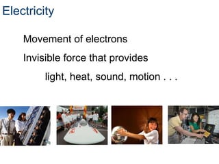
Electricity at theAtomic Level
Elements - The simplest form of matter
Atoms - Smallest piece of an element containing all of
the properties of that element
4.
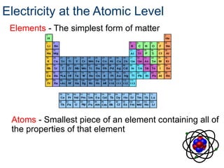
Components of anAtom
Nucleus
The center portion of
an atom containing the
protons and neutrons
Protons
Positively charged
atomic particles
Neutrons
Uncharged atomic
particles
Electricity at the Atomic Level
5.
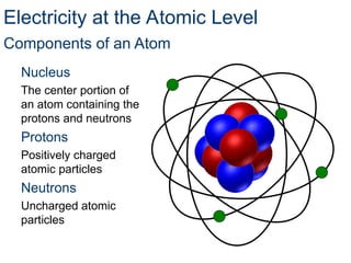
Atomic Number
The atomicnumber is
equal to the number of
protons in the nucleus
of an atom.
The atomic number
identifies the element.
How many
protons are in
this nucleus?
Electricity at the Atomic Level
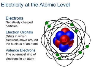
6.
Negatively charged
particles
Electron Orbitals
Orbitsin which
electrons move around
the nucleus of an atom
Valence Electrons
The outermost ring of
electrons in an atom
3D
2D
Electricity at the Atomic Level
Electrons
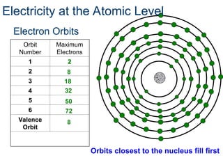
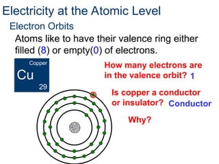
Electron Orbits
Atoms liketo have their valence ring either
filled (8) or empty(0) of electrons.
How many electrons are
in the valence orbit?
Electricity at the Atomic Level
Copper
Cu
29
1
Is copper a conductor
or insulator? Conductor
Why?
9.
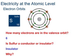
How many electronsare in the valence orbit?
6
Is Sulfur a conductor or insulator?
Insulator
Why?
Electricity at the Atomic Level
Sulfur
S
16
Electron Orbits
10.
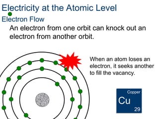
Electron Flow
An electronfrom one orbit can knock out an
electron from another orbit.
When an atom loses an
electron, it seeks another
to fill the vacancy.
Electricity at the Atomic Level
Copper
Cu
29
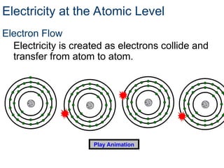
11.
Electron Flow
Electricity iscreated as electrons collide and
transfer from atom to atom.
Play Animation
Electricity at the Atomic Level
12.
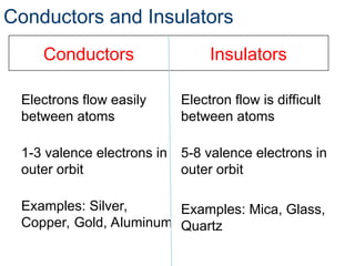
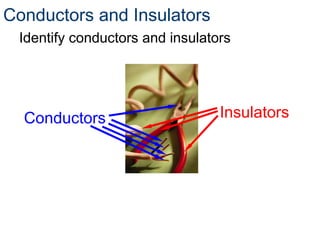
Conductors and Insulators
ConductorsInsulators
Electrons flow easily
between atoms
1-3 valence electrons in
outer orbit
Examples: Silver,
Copper, Gold, Aluminum
Electron flow is difficult
between atoms
5-8 valence electrons in
outer orbit
Examples: Mica, Glass,
Quartz
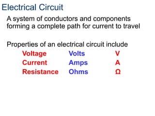
Electrical Circuit
A systemof conductors and components
forming a complete path for current to travel
Properties of an electrical circuit include
Voltage Volts V
Current Amps A
Resistance Ohms Ω
15.
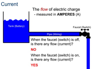
Current
The flow ofelectric charge
When the faucet (switch) is off,
is there any flow (current)?
NO
When the faucet (switch) is on,
is there any flow (current)?
YES
Tank (Battery) Faucet (Switch)
Pipe (Wiring)
- measured in AMPERES (A)
16.
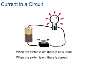
Current in aCircuit
When the switch is off, there is no current.
When the switch is on, there is current.
off on
off on
17.
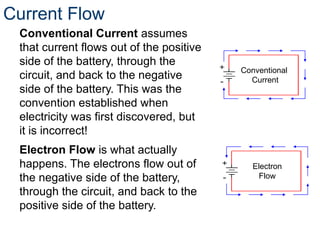
Current Flow
Conventional Currentassumes
that current flows out of the positive
side of the battery, through the
circuit, and back to the negative
side of the battery. This was the
convention established when
electricity was first discovered, but
it is incorrect!
Electron Flow is what actually
happens. The electrons flow out of
the negative side of the battery,
through the circuit, and back to the
positive side of the battery.
Electron
Flow
Conventional
Current
18.
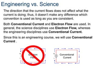
Engineering vs. Science
Thedirection that the current flows does not affect what the
current is doing; thus, it doesn’t make any difference which
convention is used as long as you are consistent.
Both Conventional Current and Electron Flow are used. In
general, the science disciplines use Electron Flow, whereas
the engineering disciplines use Conventional Current.
Since this is an engineering course, we will use Conventional
Current .
Electron
Flow
Conventional
Current
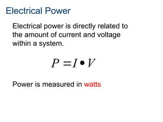
19.
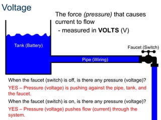
Voltage
The force (pressure)that causes
current to flow
When the faucet (switch) is off, is there any pressure (voltage)?
YES – Pressure (voltage) is pushing against the pipe, tank, and
the faucet.
When the faucet (switch) is on, is there any pressure (voltage)?
YES – Pressure (voltage) pushes flow (current) through the
system.
Tank (Battery) Faucet (Switch)
Pipe (Wiring)
- measured in VOLTS (V)
20.
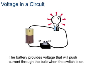
Voltage in aCircuit
The battery provides voltage that will push
current through the bulb when the switch is on.
off on
off on
21.
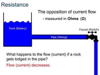
Resistance
The opposition ofcurrent flow
What happens to the flow (current) if a rock
gets lodged in the pipe?
Flow (current) decreases.
Tank (Battery) Faucet (Switch)
Pipe (Wiring)
- measured in Ohms (Ω)
22.
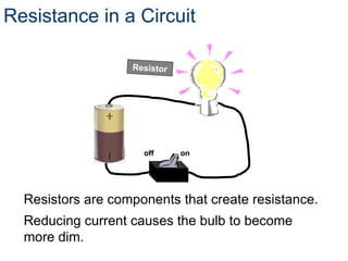
Resistance in aCircuit
Resistors are components that create resistance.
Reducing current causes the bulb to become
more dim.
off on
Resistor
23.
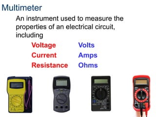
Multimeter
An instrument usedto measure the
properties of an electrical circuit,
including
Voltage Volts
Current Amps
Resistance Ohms
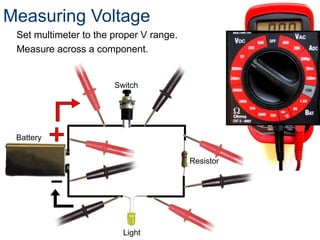
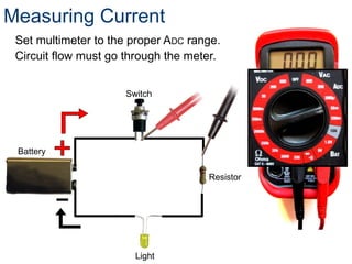
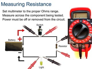
Measuring Resistance
Set multimeterto the proper Ohms range.
Measure across the component being tested.
Power must be off or removed from the circuit.
Light
Resistor
Battery
Switch
27.
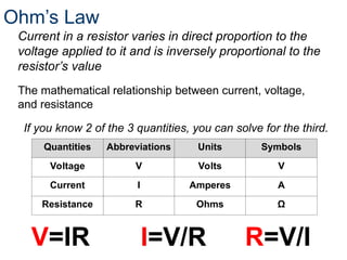
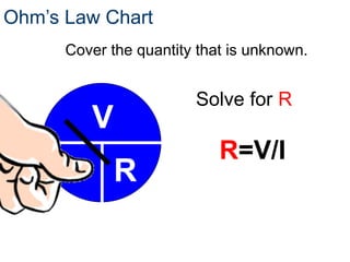
Ohm’s Law
Quantities AbbreviationsUnits Symbols
Voltage V Volts V
Current I Amperes A
Resistance R Ohms Ω
If you know 2 of the 3 quantities, you can solve for the third.
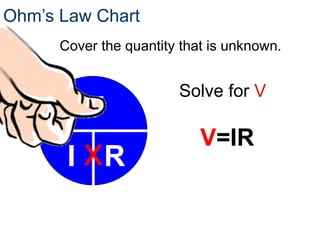
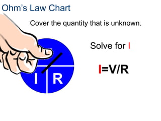
V=IR I=V/R R=V/I
The mathematical relationship between current, voltage,
and resistance
Current in a resistor varies in direct proportion to the
voltage applied to it and is inversely proportional to the
resistor’s value
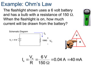
Example: Ohm’s Law
Theflashlight shown uses a 6 volt battery
and has a bulb with a resistance of 150 .
When the flashlight is on, how much
current will be drawn from the battery?
VT =
+
-
VR
IR
Schematic Diagram
mA
40
A
0.04
150
V
6
R
V
I R
R
V
I R
32.
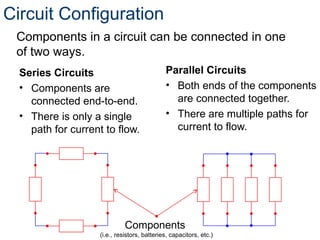
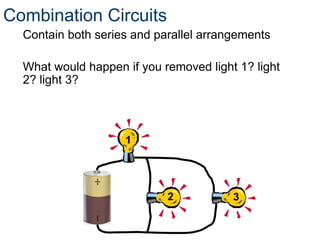
Circuit Configuration
Series Circuits
•Components are
connected end-to-end.
• There is only a single
path for current to flow.
Parallel Circuits
• Both ends of the components
are connected together.
• There are multiple paths for
current to flow.
Components
(i.e., resistors, batteries, capacitors, etc.)
Components in a circuit can be connected in one
of two ways.
33.
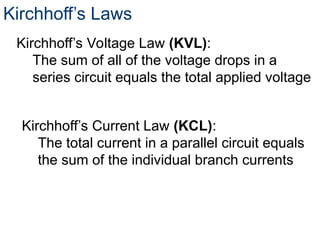
Kirchhoff’s Laws
Kirchhoff’s VoltageLaw (KVL):
The sum of all of the voltage drops in a
series circuit equals the total applied voltage
Kirchhoff’s Current Law (KCL):
The total current in a parallel circuit equals
the sum of the individual branch currents
34.
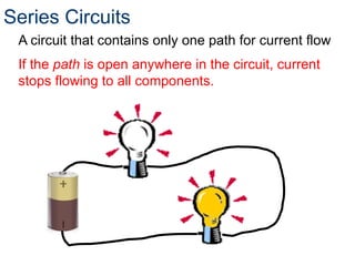
Series Circuits
A circuitthat contains only one path for current flow
If the path is open anywhere in the circuit, current
stops flowing to all components.
35.
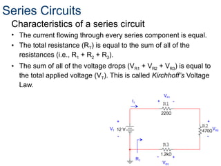
Characteristics of aseries circuit
• The current flowing through every series component is equal.
• The total resistance (RT) is equal to the sum of all of the
resistances (i.e., R1 + R2 + R3).
• The sum of all of the voltage drops (VR1 + VR2 + VR3) is equal to
the total applied voltage (VT). This is called Kirchhoff’s Voltage
Law.
VT
+
-
VR2
+
-
VR1
+ -
VR3
+
-
RT
IT
Series Circuits
36.
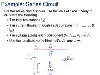
Example: Series Circuit
Forthe series circuit shown, use the laws of circuit theory to
calculate the following:
• The total resistance (RT)
• The current flowing through each component (IT, IR1, IR2, &
IR3)
• The voltage across each component (VT, VR1, VR2, & VR3)
• Use the results to verify Kirchhoff’s Voltage Law.
VT
+
-
VR2
+
-
VR1
+ -
VR3
+
-
RT
IT
IR1
IR3
IR2
37.
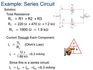
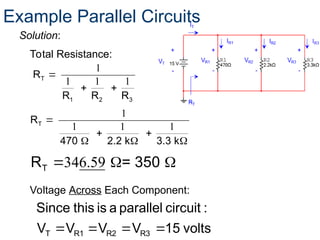
Solution:
V
I R
T
R R1R2 R3
Total Resistance:
T
T
T
V
I (Ohm's Law)
R
Current Through Each Component:
Example: Series Circuit
T
R 220 470 1.2 k
T
R 1900 1.9 k
T
12 v
I 6.3 mAmp
1.89 k
T R1 R2 R3
Since this is a series circuit:
I I I I 6.3 mAmp
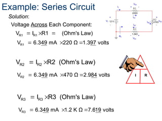
38.
R1 R1
V IR1 (Ohm's Law)
Voltage Across Each Component:
V
I R
Example: Series Circuit
Solution:
R1
V 6.349 mA 220 Ω 1.397 volts
R2 R2
V I R2 (Ohm's Law)
R2
V 6.349 mA 470 Ω 2.984 volts
R3 R3
V I R3 (Ohm's Law)
R3
V 6.349 mA 1.2 K Ω 7.619 volts
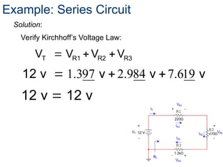
39.
T R1 R2R3
V V V V
Verify Kirchhoff’s Voltage Law:
Example: Series Circuit
Solution:
1.397 2.984 7.619
12 v v v v
12 v 12 v
40.
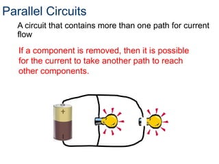
Parallel Circuits
A circuitthat contains more than one path for current
flow
If a component is removed, then it is possible
for the current to take another path to reach
other components.
41.
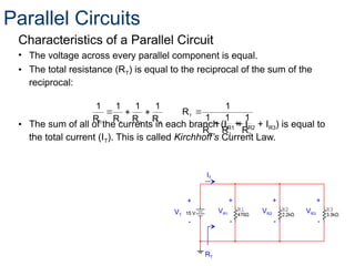
Characteristics of aParallel Circuit
• The voltage across every parallel component is equal.
• The total resistance (RT) is equal to the reciprocal of the sum of the
reciprocal:
• The sum of all of the currents in each branch (IR1 + IR2 + IR3) is equal to
the total current (IT). This is called Kirchhoff’s Current Law.
3
2
1
T
3
2
1
T
R
1
R
1
R
1
1
R
R
1
R
1
R
1
R
1
+
-
+
-
VR1
+
-
VR2 VR3
RT
VT
IT
+
-
Parallel Circuits
42.
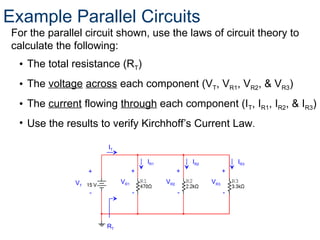
For the parallelcircuit shown, use the laws of circuit theory to
calculate the following:
• The total resistance (RT)
• The voltage across each component (VT, VR1, VR2, & VR3)
• The current flowing through each component (IT, IR1, IR2, & IR3)
• Use the results to verify Kirchhoff’s Current Law.
42
+
-
+
-
VR1
+
-
VR2 VR3
RT
VT
IT
+
-
IR1 IR2 IR3
Example Parallel Circuits
R1
R1
V
I (Ohm's Law)
R1
V
IR
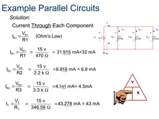
Current Through Each Component:
Solution:
Example Parallel Circuits
R1
R1
V 15 v
I 31.915 mA=32 mA
R1 470
R2
R2
V 15 v
I 6.818 mA = 6.8 mA
R2 2.2 k
.545
R3
R3
V 15 v
I 4 mA= 4.5mA
R3 3.3 k
T
T
T
V 15 v
I 43.278 mA = 43 mA
R 346.59
45.
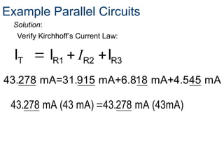
Verify Kirchhoff’s CurrentLaw:
T R1 R2 R3
I I I
I
Solution:
Example Parallel Circuits
43.278 mA=31.915 mA+6.818 mA+4.545 mA
43.278 mA (43 mA) 43.278 mA (43mA)
#21 All materials have resistance. Conductors have little resistance. Insulators provide a lot of resistance. Some electronic components (resistors) have a specific resistance. These are often needed to reduce current in order to protect other components or to adjust the amount of current that goes to other components.
#23 Sometimes the multimeter is referred to as the “Swiss Army Knife” of electricity.
Common measurements include continuity, voltage, current, and resistance. These are further discussed in this presentation and other presentations in this lesson.
#24 The positive and negative signs represent polarity and flow.
A digital multimeter will give a negative reading if the positive and negative terminals are reversed.
The voltage reading can be different between any measured component.
#32 Overview of series and parallel component configuration.