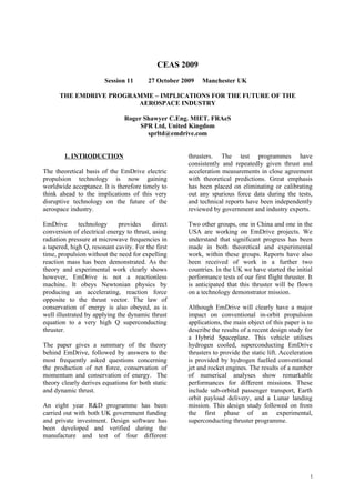
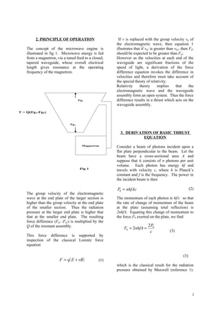
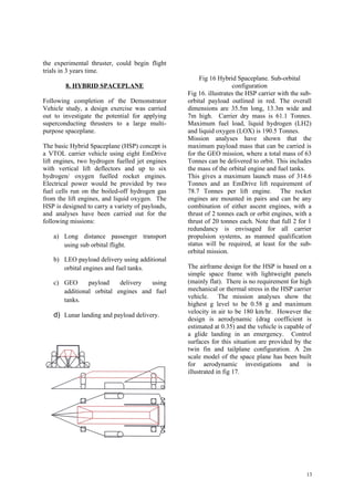
SlideShare a Scribd company logo
CEAS 2009
                        Session 11       27 October 2009   Manchester UK

      THE EMDRIVE PROGRAMME – IMPLICATIONS FOR THE FUTURE OF THE
                        AEROSPACE INDUSTRY

                                Roger Shawyer C.Eng. MIET. FRAeS
                                     SPR Ltd, United Kingdom
                                       sprltd@emdrive.com


        1. INTRODUCTION                               thrusters. The test programmes have
                                                      consistently and repeatedly given thrust and
The theoretical basis of the EmDrive electric         acceleration measurements in close agreement
propulsion technology is now gaining                  with theoretical predictions. Great emphasis
worldwide acceptance. It is therefore timely to       has been placed on eliminating or calibrating
think ahead to the implications of this very          out any spurious force data during the tests,
disruptive technology on the future of the            and technical reports have been independently
aerospace industry.                                   reviewed by government and industry experts.

EmDrive        technology    provides      direct     Two other groups, one in China and one in the
conversion of electrical energy to thrust, using      USA are working on EmDrive projects. We
radiation pressure at microwave frequencies in        understand that significant progress has been
a tapered, high Q, resonant cavity. For the first     made in both theoretical and experimental
time, propulsion without the need for expelling       work, within these groups. Reports have also
reaction mass has been demonstrated. As the           been received of work in a further two
theory and experimental work clearly shows            countries. In the UK we have started the initial
however, EmDrive is not a reactionless                performance tests of our first flight thruster. It
machine. It obeys Newtonian physics by                is anticipated that this thruster will be flown
producing an accelerating, reaction force             on a technology demonstrator mission.
opposite to the thrust vector. The law of
conservation of energy is also obeyed, as is          Although EmDrive will clearly have a major
well illustrated by applying the dynamic thrust       impact on conventional in-orbit propulsion
equation to a very high Q superconducting             applications, the main object of this paper is to
thruster.                                             describe the results of a recent design study for
                                                      a Hybrid Spaceplane. This vehicle utilises
The paper gives a summary of the theory               hydrogen cooled, superconducting EmDrive
behind EmDrive, followed by answers to the            thrusters to provide the static lift. Acceleration
most frequently asked questions concerning            is provided by hydrogen fuelled conventional
the production of net force, conservation of          jet and rocket engines. The results of a number
momentum and conservation of energy. The              of numerical analyses show remarkable
theory clearly derives equations for both static      performances for different missions. These
and dynamic thrust.                                   include sub-orbital passenger transport, Earth
                                                      orbit payload delivery, and a Lunar landing
An eight year R&D programme has been                  mission. This design study followed on from
carried out with both UK government funding           the first phase of an experimental,
and private investment. Design software has           superconducting thruster programme.
been developed and verified during the
manufacture and test of four different


                                                                                                       1
2. PRINCIPLE OF OPERATION                      If v is replaced with the group velocity vg of
                                                       the electromagnetic wave, then equation 1
    The concept of the microwave engine is             illustrates that if vg1 is greater than vg2, then Fg1
    illustrated in fig 1. Microwave energy is fed      should be expected to be greater than Fg2.
    from a magnetron, via a tuned feed to a closed,    However as the velocities at each end of the
    tapered waveguide, whose overall electrical        waveguide are significant fractions of the
    length gives resonance at the operating            speed of light, a derivation of the force
    frequency of the magnetron.                        difference equation invokes the difference in
                                                       velocities and therefore must take account of
                                                       the special theory of relativity.
                                                       Relativity      theory       implies     that     the
                                                       electromagnetic wave and the waveguide
                                                       assembly form an open system. Thus the force
                                     Fg1               difference results in a thrust which acts on the
                                                       waveguide assembly.
T = Q(Fg1-Fg2)


                               Fg2


                                                         3. DERIVATION OF BASIC THRUST
                                                                   EQUATION
                                       Magnetron
                                                       Consider a beam of photons incident upon a
                                                       flat plate perpendicular to the beam. Let the
                                                       beam have a cross-sectional area A and
                                                       suppose that it consists of n photons per unit
                                                       volume. Each photon has energy hf and
                                      Fig 1
                                                       travels with velocity c, where h is Planck’s
                                                       constant and f is the frequency. The power in
                                                       the incident beam is then

                                                       P0 = nhfAc                                         (2)
    The group velocity of the electromagnetic
    wave at the end plate of the larger section is     The momentum of each photon is hf/c so that
    higher than the group velocity at the end plate    the rate of change of momentum of the beam
    of the smaller section. Thus the radiation         at the plate (assuming total reflection) is
    pressure at the larger end plate is higher that    2nhfA. Equating this change of momentum to
    that at the smaller end plate. The resulting       the force F0 exerted on the plate, we find
    force difference (Fg1 -Fg2) is multiplied by the
    Q of the resonant assembly.                                             2 P0
                                                            F0 = 2nhfA =
                                                                             c             (3)
    This force difference is supported by
    inspection of the classical Lorentz force
    equation

                                                                                                    (3)
                        F = q( E + vB )          (1)
                                                       which is the classical result for the radiation
                                                       pressure obtained by Maxwell (reference 1).


                                                                                                            2
The derivation given here is based on Cullen       Now λg2 > λg1, due to the difference in cross-
(reference 2). If the velocity of the beam is v    section, and hence Fg1 > Fg2.
then the rate of change of momentum at the         Therefore the resultant thrust T will be
plate is 2nhfA(v/c), so that the force Fg on the
plate is in this case given by
                                                                        2 P0  λ0
                                                                                  λ 
                 2P                          (4)     T = Fg1 − Fg 2 =             − 0 
             Fg = 0 ( v / c )                                            c  λ g1 λ g 2 
                                                                                       
                  c
                                                   (7)
We now suppose that the beam enters a
vacuum-filled waveguide. The waveguide
tapers from free-space propagation, with
wavelength λ0, to dimensions that give a             4. FREQENTLY ASKED QUESTIONS
waveguide wavelength of λg and propagation
velocity vg. This is the group velocity and is     The considerable reaction caused by the New
given by                                           Scientist cover story in September 2006,
                                                   identified three questions which caused most
                      c λ0                   (5)   of the difficulties in understanding the
             vg =
                     µ r er λg                     concept.

Then from (4) and (5) (with µr = er = 1) the
force on the plate closing the end of the
waveguide is                                       (a) How can net thrust be produced ?

                           P λ
Fg =
        2 P0
             ( vg / c ) = 2c 0 λ0                  From (7) it can be seen that to maximise
                                                   thrust, the taper design should ensure λg1
         c                      g
                                                   approaches λ0 consistent with an acceptable
                                            (6)    maximum dimension. Also λg2 should
                                                   approach infinity, which occurs when the
                                                   minimum       dimension    approaches   the
                                                   propagation cut-off limit. This minimum
see Cullen (p.102 Eq. (15)).
                                                   dimension must be consistent with allowable
                                                   manufacturing and thermal tolerances.
Assume that the beam is propagated in a
vacuum-filled tapered waveguide with
                                                   The resulting design must also ensure a low
reflecting plates at each end. Let the guide
                                                   taper slope, to minimise the axial component
wavelength at the end of the largest cross-
                                                   of side wall forces. This combination of
section be λg1 and that at the smallest cross-     dimensional constraints requires an iterative
section be λg2.                                    numerical design approach, taking account of
                                                   the highly non-linear relationship between
 Then application of (6) to each plate yields      radial dimensions and guide wavelengths. This
the forces                                         relationship is illustrated in fig 2.


        2 P0 λ0                  2 P0 λ0
Fg1 =           ,       Fg 2 =
         c λ g1                   c λg 2


                                                                                                3
Fig 2 Guide wavelength for circular TMO1 at        calculated according to Einstein’s law of
                                                   addition of velocities given by
     5000
                                                                            v1 + v2
                                                                   v=
                                                                        1 + ( v1v2 ) / c 2
     4000


     3000
                                                   The second effect is that as the beam velocities
                                                   are not directly dependent on any velocity of
                                                   the waveguide, the beam and waveguide form
     2000
                                                   an open system. Thus the reactions at the end
                                                   plates are not constrained within a closed
     1000
                                                   system of waveguide and beam, but are
                                                   reactions between waveguide and beam, each
                                                   operating within its own reference frame, in an
        0
                                                   open system.
            0   200   400     600     800   1000
                 Waveguide Diameter (mm)


2 GHz                                                      From (7) and (5) we find

 It is clear that if the minimum dimension was                  2 P0  vg1 vg 2 
                                                           T=            −     
                                                                 c  c      c 
the cut off diameter, force Fg2 would be zero.
However because there would still be a                                         
significant small end plate area, the projected
area of the side wall would not equal the area
of the large end plate. Thus any attempt to
show a resultant zero net force due to
equalisation of areas is incorrect.

Note also that if the forces had been the          where
mechanical result of a working fluid within the
closed waveguide assembly, then the resultant               v g1 = cλ0 / λg1      v g 2 = cλ0 / λ g 2
force would merely introduce a mechanical                                                               .
strain in the waveguide walls. This would be
                                                   Applying the above addition law of relativistic
the result of a closed system of waveguide and
                                                   velocities we obtain
working fluid.

In the present system, the working fluid is
replaced by an electromagnetic wave                      2 P0  v g1 − v g 2  2 P0 S 0  λ0
                                                                                  =         λ 
                                                   T=                                         − 0 
propagating close to the speed of light and              c 2  1 − v g1v g 2 / c 2 
                                                                                    c  λ g1 λ g 2 
                                                                                                    
Newtonian mechanics must be replaced with
the special theory of relativity. There are two    (8)
effects to be considered in the application of
the special theory of relativity to the            where the correction factor So is
waveguide. The first effect is that as the two
forces Fg1 and Fg2 are dependent upon the                                           −1
velocities vg1 and vg2, the thrust T should be                    
                                                                      λ2    
                                                            S 0 = 1 −  0
                                                                              
                                                                   λ g1λ g 2 
                                                                             


                                                                                                            4
We suppose that the waveguide is resonant at
the frequency of the microwave beam and that         Acceleration Vector                                                     Thrust Vector
the conductive and dielectric losses are such                                                                 1
that there are Q return paths (each at power
                                                                                                          0.8
P0). Then the total thrust is finally given by
                                                                                                          0.6


                                                                                                          0.4


            2 P0 QS 0    λ0  λ      (9)                                                                 0.2
                                   


                                                           Thrust (Tc/2Po)
      T =                    − 0
                        λ          
                c        g1 λg 2
                                                                                                              0

                                                                            -1   -0.8   -0.6   -0.4   -0.2
                                                                                                         -0.2
                                                                                                                   0   0.2    0.4   0.6   0.8   1


                                                                                                         -0.4


                                                                                                         -0.6

(b) How is momentum conserved?                                                                           -0.8


                                                                                                              -1
The concept of the beam and waveguide as an                                                     Waveguide velocity (Vw /c)

open system can be illustrated by increasing
the velocity of the waveguide in the direction
of the thrust, until a significant fraction of the   Fig 3. Solution to equation 10
speed of light is reached. Let vw be the velocity
of the waveguide. Then as each plate is
moving with velocity vw the forces on the            When the waveguide is accelerated along the
plates, given by equation 6, are modified as         acceleration vector, the thrust approaches a
follows:                                             maximum of 1. However, as the velocity of
                                                     the waveguide increases in the direction of
                                                     thrust, the thrust will decrease to zero. This
         2 P0    v g1 − v w    2 P0                point is reached when vga = vgb. Fig 3 illustrates
Fg1 =                         =     v
         c2     1− v v c2      c 2 ga              the solution to equation 10 for values of vg1 =
                    g1 w                           0.95 c and vg2 = 0.05c. It can be seen that if vw
and                                                  is increased beyond the value of 0.7118c, the
                                                     thrust reverses.
         2 P0    v g 2 + vw    2 P0
Fg 2 =                        =     v              Equation 10 illustrates that the thruster is an
         c2     1 + v v c2     c 2 gb
                     g2 w                          open system, where guide velocities are
                                                     independent of waveguide velocity, and it is
                                                     the relative velocities that give rise to the
The thrust is then given by
                                                     forces. Note that if Einstein’s law for the
                                                     addition of velocities had not been used,
                                            (10)
                                                     relative velocities would exceed c, and the
            2 P0    v ga − v gb                    thrust would go above the theoretical limit of
      T=                           
            c2     1− v v c2                       1.
                       ga gb       
                                                     (c) How is energy conserved?
The solution to (10) is illustrated in Fig 3.
Note that to maintain the principle of the           We now examine the implications of the
conservation of momentum, the acceleration           principle of the conservation of energy when
of the waveguide due to thrust, is opposite to       the thrust is first measured on a static test rig,
the actual thrust direction. Thus, in Fig 3, the     and then when an engine is used to accelerate
sign convention for the waveguide velocity           a spacecraft.
axis is:
                                                     With the microwave engine mounted on a
                                                     static test rig, all the input power P0 is


                                                                                                                                                    5
converted to electrical loss. In this case the Q     where v is the average velocity over time ∆t
of the engine may be termed Qu, the unloaded         and a is the acceleration of the spacecraft.
Q.                                                   Now M.a is the force due to the acceleration of
Now                                                  the spacecraft, which opposes the thrust of the
       Pc Pc                                         engine. Then
Qu =     =
       P0 Pe
where Pc is the circulating power within the
resonant waveguide and Pe is the electrical                         2 P0Ql D f v
loss. From (9) we find                                     Pk =
                                                                           c
                          2 P0 D f Qu
                    T=                   ,
                                 c                                                             (13)
Where Df is the design factor
                                                                                               (14)
         λ   λ 
D f = S0  0 − 0 
         λ         
          g1 λ g 2 
                                                     where Ql is the loaded Q of the engine when it
             2 D f Pc                                is delivering an output power Pk.
Then      T=          .                      (11)
                c

Thus if the circulating power remains constant,      The electrical power losses Pe are assumed to
for instance in a superconducting resonant           be I2R losses and thus for any value of Q ,
waveguide, then T will remain constant. This
will be important in non spacecraft                    Pe = Q 2 Pe 0
applications where very high values of Qu
could be employed to provide a constant thrust       where Pe0 is the loss for Q=1. From the static
to counter gravitational force.                      case, we have
                                                                   P0
If the engine is mounted in a spacecraft of total        Pe 0 =       2
mass M and is allowed to accelerate from an
                                                                   Qu
initial velocity vi to a final velocity vf in time
∆t, then by equating kinetic energies we             so that
                                                                       2
obtain:                                                      Q 
                                                     Pe = P0  l 
                                                             Q                        (14)
  Pk ∆t =
          M
          2
               2
                (
            v f − vi
                     2
                             )                                u


where Pk is the output power transferred to the
spacecraft. From this we obtain                      For an accelerating spacecraft,


Pk ∆t =
          M
            ( v f − vi )( v f + vi ) ,               P0 = Pe + Pk
          2                                          Substitution of (13) and (14) into this last
                                                     equation then yields

so that                          Pk = M va    (12)             2
                                                        Ql  2Ql D f v
                                                         +
                                                       Q              =1
                                                        u      c


                                                                                                   6
Q u=5E +3          Q u=5E +4           Q u=5E +5


                                                           1


                                                          0.8


                                                          0.6


                                                  Ql/Qu
                                                          0.4


                                                          0.2


                                                           0
                                                                0           2      4       6       8          10
                                                                            Average velocity (km /s)


                                 (15)                                                    Fig 5 Specific thrust at 3km/s.


                                                                                         (d) Is EmDrive similar to anything else?

                                                                                         EmDrive is a new class of electrical machine
                                                                                         operating at microwave frequencies, and
Fig 4 Solution to equation 15.                                                           therefore bears little similarity to any other
                                                                                         device.     However, analogies are sometimes
Fig 4 shows the solution to (15) for values of                                           helpful in obtaining a mental picture of
v up to 10km/sec and for values of Qu equal                                              operating principles and the following
to 5x10³, 5x10⁴ and 5x10⁵. The value of Df is                                            mechanical      analogy     is    offered     for
taken to be 0.945.                                                                       consideration.
                                                                                         EmDrive can be considered as an
For Df equal to 0.945 and an average velocity                                            “electromagnetic flywheel”.         As with a
of 3 km/s, the specific thrust is obtained from                                          mechanical flywheel, a resonant cavity can
(9) and (15) and is given in fig 5. This                                                 store energy in the form of momentum. Due
illustrates that the specific thrust increases to a                                      to the asymmetric geometry of the EmDrive
maximum of 333 mN/kW at this velocity.                                                   cavity, the stored momentum can produce a
                                                                                         linear force, which if used to accelerate a
                                                                                         mass, transfers some of the momentum from
                                                                                         the cavity. This transfer results in a loss of Q,
                           350                                                           and hence a reduction in the force available.
                                                                                         However unlike a mechanical flywheel, the
                           300
                                                                                         cavity is able to store and replace momentum
 Specific thrust (mN/kW)


                           250                                                           very rapidly. The time constant of, a simple
                                                                                         cavity operating at 4 GHz with a Q of 50,000
                           200                                                           is 2 microseconds. Thus if acceleration is
                                                                                         restricted, as with a large spacecraft being
                           150
                                                                                         propelled with low thrust, continuous
                           100
                                                                                         momentum transfer can take place, whilst
                                                                                         maintaining the high Q.
                           50

                            0
                            1000        10000    100000             1000000               5. EXPERIMENTAL PROGRAMME
                                          Unloaded Q


                                                                                                                                         7
The first experimental thruster was a 160 mm
diameter device, operating at 2.45 GHz. The        To obtain the predicted thrust, the engine was
design factor, calculated from as-built            required to maintain stable resonance at this
measurements of the thruster geometry was          high Q value.      Major design challenges
0.497. In 2001 a test programme was started        included thermal compensation, tuning control
and an unloaded Q of 5,900 was measured.           and source matching.
The maximum thrust, measured using a
precision balance was 16mN for an input            The engine was tested in a large static test rig
power of 850W, which is very close to the          employing a calibrated composite balance to
thrust of 16.6mN predicted from equation (9).      measure thrust in both vertical and horizontal
                                                   directions. A total of 134 test runs were carried
The thrust could be varied from zero to            out over the full performance envelope.
maximum by varying the input power, or by
varying the resonant frequency of the thruster.
Considerable efforts were made to test for                 6

possible thermal and electromagnetic spurious
effects. The primary method was to carry out               4
all tests in both nominal and inverted
orientations, and to take the mean of the
results. The thruster was also sealed into a               2
hermetic enclosure to eliminate buoyancy                                                  Power
effects of the cooling air. Three different                                               Up
                                                           0
types of test rig were used, two using 1 mg                                               Down
resolution balances in a counterbalance test rig                                          Horizontal

and one using a 100 mg resolution balance in a            -2
direct measurement of thruster weight.

Comparison of the rates of increase of thrust             -4

for the different spring constants, using pulsed
input power, gave a clear proof that the thrust           -6
was produced by momentum transfer and was                      20 40     60 80 100 120
not due to any “undefined” spurious effect.                            Time (secs)
The total test programme encompassed 450
test runs of periods up to 50 seconds, using 5
different magnetrons.                              Fig 7. Demonstrator Engine Static Test Data

In 2003 a Demonstrator Engine development          Fig 7 gives test results for 3 Vertical Thrust
programme was started. Unlike the first            test runs under the same input and tuner
experimental thruster, the Demonstrator            conditions but for thrust vectors in the Up,
Engine was rated for continuous operation and      Down and Horizontal directions. This clearly
extensive design work was required to              illustrates the loss of measured weight for the
increase the specific thrust by raising the        Up vector, the increase in measured weight for
design factor and unloaded Q.                      the Down vector, and a mean weight change
                                                   close to zero, for the horizontal vector. These
The engine was built to operate at 2.45 GHz,       early, low Q, comparative tests yielded
with a design factor of 0.844 and has a            specific thrusts around 80mN/kW.
measured maximum Q of 45,000 for an overall
diameter of 280 mm. The microwave source is
a water cooled magnetron with a variable
output power up to a maximum of 1.2 kW.


                                                                                                       8
Fig 8 shows the results for a later, higher Q,        Fig 9. Demonstrator Engine on Dynamic Test
test run, with the engine on the balance and
then with it suspended above the balance. This        The engine was then mounted on a dynamic
illustrates the thrust measurements were not          test rig enabling it to be “flown” on a rotary air
subject to EMC effects. Specific thrust for this      bearing, as shown in fig 9.
test was 214mN/kW.                                    The tests simulated the engine moving a
                                                      100Kg spacecraft in weightless conditions.

                                                      The test programme included acceleration and
                                                      deceleration runs in both directions, and
                                                      confirmed the thrust levels measured in the
                                                      static tests.


                                                           7


     5                                                     6


     4                                                     5


     3                                                     4
                                                                                               Velocity
                                                                                               Freq
                                             Thrust                                            Power
                                                           3
     2                                       Power
                                             EMC

                                                           2
      1


                                                            1
     0


                                                           0
     -1                                                         100   150   200   250   300
          30   50       70        90   110                              Time (secs)
                    Time (secs)


                                                      Fig 10. Dynamic test results


Fig 8. Electromagnetic Compatibility (EMC)            Fig 10 gives the result of a typical test run,
                                                      where the Demonstrator Engine produced a
                                                      thrust of 10.4 gm against a calibrated friction
                                                      torque of 7.1 gm. Input power was 421W,
                                                      giving a specific thrust of 243 mN/kW.

                                                      The frequency offset curve shows that initial
                                                      magnetron thermal drift ends with frequency
                                                      lock. At this point, 130 secs into the test run,


                                                                                                          9
the velocity data shows the start of
acceleration under power. The prior thermal
drift period, with no acceleration, shows that
the thrust is not a result of spurious thermal
effects. When the power is turned off, at 210                                   Thruster
secs, there is a coast period as the slosh effects
of 5kg of coolant maintain a reduced
acceleration. This is followed by the
deceleration due to the friction torque. A
maximum velocity of 2cm/s was achieved and                              isolators
a total distance of 185cm was “flown”.
                                                                                       TWTAs

The direction of acceleration was opposite to
the direction of thrust, thus conclusively
proving that the engine obeys Newton’s laws,
and that although no reaction mass is ejected,                FGU
the engine is not a reactionless machine. An
electrical reaction occurs between the EM
wave and the reflector surfaces of the
resonator, resulting in an input impedance
change with acceleration. This is seen in the
power curve in fig 10.                               Fig 11. Flight Engine Block Diagram

                                                     Using the flight model design as the starting
 6.FLIGHT THRUSTER PROGRAMME                         point, two lines of development will be
                                                     followed.
The Flight thruster programme covers the
design and development of a 300 Watt C Band          Thrust Vector control.
flight thruster. This has a specified thrust of      A single plane, 360 degree, pointing
85 mN, and a mass of 2.92Kg. Overall                 mechanism will be developed and qualified to
dimensions are 265mm diameter at the                 enable a set of 4 FM thrusters, each mounted
baseplate and a height of 164mm.                     on a mechanism, one on each spacecraft side
                                                     panel, to carry out full 3 axis AOCS functions
The thruster is designed to be powered from          with the required redundancy. As there are no
existing flight qualified TWTAs, which are           plume restrictions, the mechanism can be
driven from a dual redundant frequency               mounted inside the spacecraft, thus easing the
generator unit (FGU) The FGU includes a              environment specification. With each thruster
frequency control loop using feedback signals        orientated along the same axis, primary
from the thruster, as shown in the functional        propulsion for orbit changing of medium sized
block diagram of the complete Flight Engine          satellites is available.
Fig 11.
                                                     High Power operation.
                                                     By mounting the thruster externally on the
                                                     spacecraft, on the lower panel where the ABM
                                                     is normally mounted, a set of high power
                                                     thrusters can provide the primary propulsion
                                                     for LEO to GEO transfer of large satellites. A
                                                     high power rating of 3.5kW per thruster can be
                                                     achieved by updating the design, together with


                                                                                                 10
the addition of radiating fins. This would                                                           Rs @ 3.83GHz
produce a target static thrust of 1N per
thruster.                                                         100


                                                                  90


                                                                  80


      7.SUPERCONDUCTING                                           70


   DEMONSTRATOR PROGRAMME


                                                 Rs (mico Ohms)
                                                                  60


                                                                  50

The first phase of this programme was an                          40

experimental superconducting thruster. This                       30

low power, HTS device operates at liquid                          20

nitrogen temperature, and is designed for very                    10
high Q and consequently high specific thrust.                      0
                                                                        5   10   15   20   25   30   35     40    45      50   55   60   65   70   75   80
                                                                                                          Tem p (deg K)


                                                                                       Fig 13 Surface Resistivity

                                                    For the Demonstrator Thruster, cooling will be
                                                    by liquid hydrogen. The design resistivity at
                                                    20deg K is therefore taken as 11.8 x 10⁻⁶
                                                    Ohms. This value was then used in the same
                                                    design software used for the experimental 2G
                                                    thruster. The resulting thrust was calculated as
                                                    143kg for 6kW input.

                                                    A design study was then undertaken on a
                                                    simple 500kg unmanned Demonstrator
Fig 12      Experimental     Superconducting        Vehicle, illustrated in Fig 14. The basic
Thruster                                            vehicle consists of a 700 litre horizontal liquid
                                                    hydrogen tank, supported by four lift engines.
Fig 12 shows the thruster, which operates at
3.8 GHz, and was designed using an update of        A lift engine is based on the Demonstrator
the software used for the previous S band           Thruster in a 5 litre dewar, mounted on a 2
designs. Super-conducting surfaces are formed       axis +/- 30 degree gimbal mechanism. Two
from YBCO thin films on sapphire substrates.        3kW Travelling Wave Tubes (TWT) are
                                                    positioned below the thruster. Mounted below
Small signal testing at 77 deg K confirmed the      the TWTs are two Electric Power Conditioners
design, with a Q of 6.8x10⁶ being measured.         (EPC) providing the high       voltages to the
                                                    TWTs.
Fig 13 shows the surface resistivity of the
superconducting thruster based on specified         The total mass of the lift engine is predicted as
manufacturer’s data, updated for the measured       25.2 kg. This was calculated using the
data.                                               measured mass of the experimental thruster,
                                                    together with scaled masses of a flight TWT
                                                    and EPC.
                                                    An attitude control unit using feedback signals
                                                    from a laser gyroscope is used to maintain the
                                                    thrust axis vertical over the full gimbal range.
                                                    A frequency generator and control unit
                                                    (FGCU) completes the Lift engine.


                                                                                                                                                   11
600


To provide acceleration, the waste hydrogen
gas boiled off from cooling the lift engines is                                 500


used to power a pair of small Jet engines. A
hydrogen fuelled motor-generator set is used                                    400


to provide D.C. power. The jet engines are


                                                       Total Lift Thrust (kg)
gimballed in one plane to provide horizontal or                                 300


vertical thrust. Aerodynamic performance is
improved with the addition of two side body                                     200


fairings.
                                                                                100


The vehicle which is illustrated in fig 14 has
overall dimensions of 3.73m long, 1.91m wide                                     0
                                                                                      0.1     1              10              100   1000
and 1.16m high.                                                                                    Average Velocity (m /s)


                                                                                            Fig 15 Dynamic thrust

                                                      For 6kW of microwave input power at each
                                                      thruster, the total lift thrust is 573kg. Thus for
                                                      an estimated total vehicle mass of 477kg, the
                                                      vehicle would start to accelerate upwards.
                                                      However as the average velocity goes above
                                                      1m/s, the lift thrust approaches the vehicle
                                                      mass, and acceleration stops. This is simply
                                                      the principle of the conservation of energy at
                                                      work, with energy used to accelerate the
        Fig 14 Demonstrator Vehicle                   vehicle being lost from the stored energy in
                                                      the thruster, hence lowering the Q.

                                                      Clearly, to achieve a useful rate of climb, the
The design of the vehicle results from iterating      jet engines need to be rotated to give vertical
a mass, power and thrust analysis with inputs         thrust and the lift engine operation needs
from four mission analyses. The mass,                 compensation to avoid losing stored energy. A
dimensions and performance of the jet engines         method of compensation has been established
are scaled from the data available for the AMT        theoretically, and one of the main objectives of
Titan UAV engine. The power generator is              the Demonstrator Vehicle programme will to
based on an uprated ROTAX 503 aero engine             be to show this compensation in operation.
driving a high speed 36 kW alternator.
                                                      The flight envelope was investigated by
From the dynamic thrust equation, (equation           running 4 numerical mission analyses. These
15), it is clear that if the lift engine is used to   gave a maximum rate of vertical ascent of
accelerate the vehicle upwards, then at the           52m/s (170ft/s) and a maximum speed of
high Q values obtained with superconducting           118m/s (230 knots) at a maximum altitude of
thrusters, thrust will decrease rapidly. This is      12.6km (41,300ft). If the altitude is restricted
illustrated for the Demonstrator Vehicle in Fig       to 1.34km (4,400 ft) then a full liquid
15.                                                   hydrogen fuel load will give a maximum range
                                                      of 97km (60 miles).

                                                      It is estimated that this very simple vehicle,
                                                      using four, liquid hydrogen cooled, versions of


                                                                                                                                     12
the experimental thruster, could begin flight
trials in 3 years time.
                                                       Fig 16 Hybrid Spaceplane. Sub-orbital
        8. HYBRID SPACEPLANE                                        configuration
                                                  Fig 16. illustrates the HSP carrier with the sub-
Following completion of the Demonstrator          orbital payload outlined in red. The overall
Vehicle study, a design exercise was carried      dimensions are 35.5m long, 13.3m wide and
out to investigate the potential for applying     7m high. Carrier dry mass is 61.1 Tonnes.
superconducting thrusters to a large multi-       Maximum fuel load, liquid hydrogen (LH2)
purpose spaceplane.                               and liquid oxygen (LOX) is 190.5 Tonnes.
                                                  Mission analyses have shown that the
The basic Hybrid Spaceplane (HSP) concept is      maximum payload mass that can be carried is
a VTOL carrier vehicle using eight EmDrive        for the GEO mission, where a total mass of 63
lift engines, two hydrogen fuelled jet engines    Tonnes can be delivered to orbit. This includes
with vertical lift deflectors and up to six       the mass of the orbital engine and fuel tanks.
hydrogen/ oxygen fuelled rocket engines.          This gives a maximum launch mass of 314.6
Electrical power would be provided by two         Tonnes and an EmDrive lift requirement of
fuel cells run on the boiled-off hydrogen gas     78.7 Tonnes per lift engine. The rocket
from the lift engines, and liquid oxygen. The     engines are mounted in pairs and can be any
HSP is designed to carry a variety of payloads,   combination of either ascent engines, with a
and analyses have been carried out for the        thrust of 2 tonnes each or orbit engines, with a
following missions:                               thrust of 20 tonnes each. Note that full 2 for 1
                                                  redundancy is envisaged for all carrier
    a) Long distance passenger transport          propulsion systems, as manned qualification
       using sub orbital flight.                  status will be required, at least for the sub-
                                                  orbital mission.
    b) LEO payload delivery using additional
       orbital engines and fuel tanks.            The airframe design for the HSP is based on a
                                                  simple space frame with lightweight panels
    c) GEO      payload    delivery  using        (mainly flat). There is no requirement for high
       additional orbital engines and fuel        mechanical or thermal stress in the HSP carrier
                                                  vehicle. The mission analyses show the
       tanks.
                                                  highest g level to be 0.58 g and maximum
                                                  velocity in air to be 180 km/hr. However the
    d) Lunar landing and payload delivery.
                                                  design is aerodynamic (drag coefficient is
                                                  estimated at 0.35) and the vehicle is capable of
                                                  a glide landing in an emergency. Control
                                                  surfaces for this situation are provided by the
                                                  twin fin and tailplane configuration. A 2m
                                                  scale model of the space plane has been built
                                                  for aerodynamic investigations and is
                                                  illustrated in fig 17.


                                                                                                 13
At this height, the orbit engines are fired to
                                                    accelerate the spaceplane to a cruise velocity
                                                    of 4km/s. At 90 minutes into the flight,
                                                    deceleration starts, using the lift engines in a
                                                    braking mode. Note that when used for
                                                    deceleration, the EmDrive lift engines are not
                                                    subject to the dynamic thrust limitation, as no
                                                    energy is being lost from the stored energy in
                                                    the resonant cavity. Descent and a vertical
                                                    landing are controlled by both the lift engines
                                                    and the jet engines.

     Fig 17. 2m scale model of spaceplane           The two Earth orbit missions use the carrier
                                                    vehicle to achieve an altitude above the
                                                    required orbit height. The takeoff and landing
Each mission was subject to a numerical             phases are similar to the sub-orbital mission,
analysis to calculate acceleration, velocity,       with the ascent phase extended until the
height and distance from the thrust, drag and       required altitude is reached. The payload
mass data for time increments through each          vehicle, comprising payload, rocket engines,
phase of the mission. The results of the            and fuel tanks, is then dropped from the carrier
analyses were then used to iteratively optimise     vehicle and the engines are ignited. For the
the spaceplane design.                              LEO mission, two 100 tonne thrust engines are
                                                    required, whilst for the GEO mission only one
The results of the mission analyses are given       is used. For these missions the spaceplane
in table 1.                                         carrier vehicle can be viewed as a “space
                                                    elevator without cables”.
                             Missions
            Sub       LEO         GEO     Lunar
            orbital                                 The Lunar landing analysis illustrates the
Distance    16,890    250        36,000   382,538   dramatic improvements possible for future
(km)
Mission     2.63      1.98       59.83    105.58    missions. The Earth orbit cruise phase is
time                                                extended to a distance where the vehicle
(hours)                                             comes within the gravitational influence of the
Max         4.14      7.79       3.07     2.17
velocity                                            moon. The lift engines are then used to control
(km/s)                                              descent to the Lunar surface. A precise landing
Max         0.32                          0.58      position can be achieved by using the
Carrier g
Max                   4          1.5                gimballed ascent engines for horizontal and
Payload                                             vertical movement, whilst the lift engines
g                                                   provide hover. Lunar take-off uses the
Payload     58.7      15.9       49.4     44.1
Mass                                                20 tonne thrust engines to achieve return
(Tonnes)                                            velocity, with the lift engines used to control
                                                    deceleration and descent into the Earths
        Table 1. Mission Analysis Results           atmosphere. The landing phase is similar to
                                                    the previous missions.
The London to Sydney sub-orbital mission
starts with a vertical take-off with the
spaceplane in a horizontal attitude. Lift is
provided by the EmDrive thrusters and vertical
acceleration by the jet engines. At 12km                         9. CONCLUSIONS
altitude the ascent rocket engines are fired to
maintain the climb to a cruise altitude of 96km


                                                                                                  14
The theory and principles of operation of
EmDrive have been given, together with the          Finally, the need to refocus the aircraft
derivation of the equations used to predict         industry in the face of these technology
performance. The development of the theory          changes, will also lead to space applications
and its verification have been supported by a       becoming important. Solar Power Satellites
lengthy experimental and demonstrator               form a large future market, which clearly
programme in the UK. Some results from this         requires low cost access to GEO. The Hybrid
programme have been given. This theoretical         Spaceplane will finally make this industry
and experimental work has been independently        financially viable, and at the same time
verified by groups working outside Europe. It       provide an answer to the global need for a
is therefore confidently predicted that within a    green energy source.
few years, the use of first generation EmDrive
technology      will      provide     significant
improvements in mission performance, for all                ACKNOWLEDGEMENTS
space applications. It is important that Europe
does not lose out in this field.                    The author is grateful for the assistance given
                                                    by colleagues in SPR Ltd, by Dr R B Paris of
However the major impact of this technology         Abertay University, Dundee, by J W Spiller of
will occur in the aircraft industry when second     Astrium UK Ltd and by Professor J Lucas of
generation superconducting EmDrive thrusters        The University of Liverpool.         The early
are used as a lift engines in hybrid air and        theoretical     work      and     experimental
space vehicles. Once the requirement for            programmes were carried out with support
aerodynamic lift, or ballistic trajectory, is       from the Department of Trade and Industry
removed from air transport or space vehicles,       under their SMART award scheme, and then
mission analysis has to be re-thought. The          under a Research and Development grant.
design studies for an early Demonstrator            Recent programmes have been funded by
Vehicle and a future Spaceplane have shown          substantial shareholder investment.
that small VTOL vehicles, using simple low
stressed airframe design, could capture the
personal transport market. The combination of
the commercial microwave industry and a                            REFERENCES
future automobile industry, with liquid
hydrogen storage and fuel cell capability,
would render the existing short and medium          1.       MAXWELL J.C. ‘A Treatise on
haul aircraft industry redundant.                   Electricity and Magnetism’
                                                    1st Edition (Oxford University Press 1873)
The future of the aircraft industry would then      p.391.
rely on the high speed long distance sub-
orbital spaceplane. However this requires no        2.      CULLEN A.L. ‘Absolute Power
improvement in existing airframe design, other      Measurements at Microwave Frequencies’
than an ability to operate in vacuum. No high       IEE Proceedings Vol 99 Part IV 1952 P.100
velocity in the atmosphere is required, and the
vehicle is not subject to high g forces or
extreme thermal environments. London to
Sydney in under 3 hours, using hydrogen fuel
could be a reality in under 10 years, although
it may not be a European vehicle that
demonstrates this. VTOL is of course part of
the attraction of all EmDrive based
applications.


                                                                                                 15

More Related Content

What's hot

Magnetic nanostructures
Magnetic nanostructuresMagnetic nanostructures
Magnetic nanostructures
Springer
 
Electron
ElectronElectron
Electron
LarryReed15
 
Polarization bremsstrahlung on atoms, plasmas, nanostructures and solids
Polarization bremsstrahlung on atoms, plasmas, nanostructures and solidsPolarization bremsstrahlung on atoms, plasmas, nanostructures and solids
Polarization bremsstrahlung on atoms, plasmas, nanostructures and solids
Springer
 
Romiya_HR_presenetation
Romiya_HR_presenetationRomiya_HR_presenetation
Romiya_HR_presenetation
Romiya Bose
 
Phys 4190 lec (3)
Phys 4190 lec (3)Phys 4190 lec (3)
Phys 4190 lec (3)
Dr. Abeer Kamal
 
Study of de broglie wavelength of electrons
Study of de broglie wavelength of electronsStudy of de broglie wavelength of electrons
Study of de broglie wavelength of electrons
SubhamChakraborty28
 
Hp 22 win
Hp 22 winHp 22 win
Hp 22 win
josoborned
 
Principle of Electric Field - Physics - by Arun Umrao
Principle of Electric Field - Physics - by Arun UmraoPrinciple of Electric Field - Physics - by Arun Umrao
Principle of Electric Field - Physics - by Arun Umrao
ssuserd6b1fd
 
Gravity
GravityGravity
Gravity
LarryReed15
 
Chapter 3 wave_optics
Chapter 3 wave_opticsChapter 3 wave_optics
Chapter 3 wave_optics
Gabriel O'Brien
 
The plasmamagnet
The plasmamagnetThe plasmamagnet
The plasmamagnet
Clifford Stone
 
Deep Inelastic Scattering at HERA (Hadron-Electron Ring Acceleartor)
Deep Inelastic Scattering at HERA (Hadron-Electron Ring Acceleartor)Deep Inelastic Scattering at HERA (Hadron-Electron Ring Acceleartor)
Deep Inelastic Scattering at HERA (Hadron-Electron Ring Acceleartor)
SubhamChakraborty28
 
13.2
13.213.2
Physics dictionary for CBSE, ISCE, Class X Students by Arun Umrao
Physics dictionary for CBSE, ISCE, Class X Students by Arun UmraoPhysics dictionary for CBSE, ISCE, Class X Students by Arun Umrao
Physics dictionary for CBSE, ISCE, Class X Students by Arun Umrao
ssuserd6b1fd
 
Electromagnetic fields of time-dependent magnetic monopole
Electromagnetic fields of time-dependent magnetic monopoleElectromagnetic fields of time-dependent magnetic monopole
Electromagnetic fields of time-dependent magnetic monopole
IOSR Journals
 
Electromagnetic waves
Electromagnetic wavesElectromagnetic waves
Electromagnetic waves
kveerabhadrarao1
 
Class 12th physics magnetism ppt
Class 12th physics magnetism pptClass 12th physics magnetism ppt
Class 12th physics magnetism ppt
Arpit Meena
 
Quantum chemistry-B SC III-SEM-VI
 Quantum chemistry-B SC III-SEM-VI Quantum chemistry-B SC III-SEM-VI
Quantum chemistry-B SC III-SEM-VI
Shri Shivaji Science College Amravati
 
Chapter 3b
Chapter 3bChapter 3b
Chapter 3b
Gabriel O'Brien
 

What's hot (19)

Magnetic nanostructures
Magnetic nanostructuresMagnetic nanostructures
Magnetic nanostructures
 
Electron
ElectronElectron
Electron
 
Polarization bremsstrahlung on atoms, plasmas, nanostructures and solids
Polarization bremsstrahlung on atoms, plasmas, nanostructures and solidsPolarization bremsstrahlung on atoms, plasmas, nanostructures and solids
Polarization bremsstrahlung on atoms, plasmas, nanostructures and solids
 
Romiya_HR_presenetation
Romiya_HR_presenetationRomiya_HR_presenetation
Romiya_HR_presenetation
 
Phys 4190 lec (3)
Phys 4190 lec (3)Phys 4190 lec (3)
Phys 4190 lec (3)
 
Study of de broglie wavelength of electrons
Study of de broglie wavelength of electronsStudy of de broglie wavelength of electrons
Study of de broglie wavelength of electrons
 
Hp 22 win
Hp 22 winHp 22 win
Hp 22 win
 
Principle of Electric Field - Physics - by Arun Umrao
Principle of Electric Field - Physics - by Arun UmraoPrinciple of Electric Field - Physics - by Arun Umrao
Principle of Electric Field - Physics - by Arun Umrao
 
Gravity
GravityGravity
Gravity
 
Chapter 3 wave_optics
Chapter 3 wave_opticsChapter 3 wave_optics
Chapter 3 wave_optics
 
The plasmamagnet
The plasmamagnetThe plasmamagnet
The plasmamagnet
 
Deep Inelastic Scattering at HERA (Hadron-Electron Ring Acceleartor)
Deep Inelastic Scattering at HERA (Hadron-Electron Ring Acceleartor)Deep Inelastic Scattering at HERA (Hadron-Electron Ring Acceleartor)
Deep Inelastic Scattering at HERA (Hadron-Electron Ring Acceleartor)
 
13.2
13.213.2
13.2
 
Physics dictionary for CBSE, ISCE, Class X Students by Arun Umrao
Physics dictionary for CBSE, ISCE, Class X Students by Arun UmraoPhysics dictionary for CBSE, ISCE, Class X Students by Arun Umrao
Physics dictionary for CBSE, ISCE, Class X Students by Arun Umrao
 
Electromagnetic fields of time-dependent magnetic monopole
Electromagnetic fields of time-dependent magnetic monopoleElectromagnetic fields of time-dependent magnetic monopole
Electromagnetic fields of time-dependent magnetic monopole
 
Electromagnetic waves
Electromagnetic wavesElectromagnetic waves
Electromagnetic waves
 
Class 12th physics magnetism ppt
Class 12th physics magnetism pptClass 12th physics magnetism ppt
Class 12th physics magnetism ppt
 
Quantum chemistry-B SC III-SEM-VI
 Quantum chemistry-B SC III-SEM-VI Quantum chemistry-B SC III-SEM-VI
Quantum chemistry-B SC III-SEM-VI
 
Chapter 3b
Chapter 3bChapter 3b
Chapter 3b
 

Similar to Emdrive Ceas 2009 Paper

Em drive basic theory
Em drive basic theoryEm drive basic theory
Em drive basic theory
Tibor Szász
 
AME441AL_Final_Report
AME441AL_Final_ReportAME441AL_Final_Report
AME441AL_Final_Report
Matt Tonokawa
 
Antenna basics from-r&s
Antenna basics from-r&sAntenna basics from-r&s
Antenna basics from-r&s
Saurabh Verma
 
Cbse physisc question paper 2014 1
Cbse physisc question paper 2014 1Cbse physisc question paper 2014 1
Cbse physisc question paper 2014 1
Anushri Kocher
 
GAMMA-RAY SPECTROSCOPY
GAMMA-RAY SPECTROSCOPYGAMMA-RAY SPECTROSCOPY
GAMMA-RAY SPECTROSCOPY
MOIN KHAN HUSSAIN
 
6) A beam of light with red and blue components of wavelengths.docx
6) A beam of light with red and blue components of wavelengths.docx6) A beam of light with red and blue components of wavelengths.docx
6) A beam of light with red and blue components of wavelengths.docx
alinainglis
 
Galvanomagnetic Effects Sensors Based On Hall Effect
Galvanomagnetic Effects Sensors Based On Hall EffectGalvanomagnetic Effects Sensors Based On Hall Effect
Galvanomagnetic Effects Sensors Based On Hall Effect
petousis
 
Serena barbanotti INFN milano
Serena barbanotti INFN milanoSerena barbanotti INFN milano
Serena barbanotti INFN milano
adamas comunicazione
 
Physics Sample Paper with General Instruction for Class - 12
Physics Sample Paper with General Instruction for Class - 12Physics Sample Paper with General Instruction for Class - 12
Physics Sample Paper with General Instruction for Class - 12
Learning Three Sixty
 
Unit 1
Unit 1Unit 1
Simulation of p-GaN/ i-InGaN/n-GaN Solar Cell
Simulation of p-GaN/ i-InGaN/n-GaN Solar CellSimulation of p-GaN/ i-InGaN/n-GaN Solar Cell
Simulation of p-GaN/ i-InGaN/n-GaN Solar Cell
Iktiham Bin Taher
 
Radiation of an accelerated charge
Radiation of an accelerated chargeRadiation of an accelerated charge
Radiation of an accelerated charge
ijeljournal
 
Radiation of an Accelerated Charge
Radiation of an Accelerated Charge  Radiation of an Accelerated Charge
Radiation of an Accelerated Charge
ijeljournal
 
Radiation of an Accelerated Charge
Radiation of an Accelerated ChargeRadiation of an Accelerated Charge
Radiation of an Accelerated Charge
ijeljournal
 
Movimiento De Una Partícula Cargada En Un Campo Eléctrico Y En Un Campo Magné...
Movimiento De Una Partícula Cargada En Un Campo Eléctrico Y En Un Campo Magné...Movimiento De Una Partícula Cargada En Un Campo Eléctrico Y En Un Campo Magné...
Movimiento De Una Partícula Cargada En Un Campo Eléctrico Y En Un Campo Magné...
Gregory Zuñiga
 
Quantum physics
Quantum physicsQuantum physics
Quantum physics
JFG407
 
NMR spectroscopy
NMR spectroscopy NMR spectroscopy
NMR spectroscopy
AnukrittiMehra
 
636883main fdr talk_niac_2012_final
636883main fdr talk_niac_2012_final636883main fdr talk_niac_2012_final
636883main fdr talk_niac_2012_final
Clifford Stone
 
Great pyramid giza alternative energy pg circular times
Great pyramid giza  alternative energy pg circular timesGreat pyramid giza  alternative energy pg circular times
Great pyramid giza alternative energy pg circular times
tavennerpride
 
SPM PHYSICS FORM 5 electronics
SPM PHYSICS FORM 5 electronicsSPM PHYSICS FORM 5 electronics
SPM PHYSICS FORM 5 electronics
Max Wong
 

Similar to Emdrive Ceas 2009 Paper (20)

Em drive basic theory
Em drive basic theoryEm drive basic theory
Em drive basic theory
 
AME441AL_Final_Report
AME441AL_Final_ReportAME441AL_Final_Report
AME441AL_Final_Report
 
Antenna basics from-r&s
Antenna basics from-r&sAntenna basics from-r&s
Antenna basics from-r&s
 
Cbse physisc question paper 2014 1
Cbse physisc question paper 2014 1Cbse physisc question paper 2014 1
Cbse physisc question paper 2014 1
 
GAMMA-RAY SPECTROSCOPY
GAMMA-RAY SPECTROSCOPYGAMMA-RAY SPECTROSCOPY
GAMMA-RAY SPECTROSCOPY
 
6) A beam of light with red and blue components of wavelengths.docx
6) A beam of light with red and blue components of wavelengths.docx6) A beam of light with red and blue components of wavelengths.docx
6) A beam of light with red and blue components of wavelengths.docx
 
Galvanomagnetic Effects Sensors Based On Hall Effect
Galvanomagnetic Effects Sensors Based On Hall EffectGalvanomagnetic Effects Sensors Based On Hall Effect
Galvanomagnetic Effects Sensors Based On Hall Effect
 
Serena barbanotti INFN milano
Serena barbanotti INFN milanoSerena barbanotti INFN milano
Serena barbanotti INFN milano
 
Physics Sample Paper with General Instruction for Class - 12
Physics Sample Paper with General Instruction for Class - 12Physics Sample Paper with General Instruction for Class - 12
Physics Sample Paper with General Instruction for Class - 12
 
Unit 1
Unit 1Unit 1
Unit 1
 
Simulation of p-GaN/ i-InGaN/n-GaN Solar Cell
Simulation of p-GaN/ i-InGaN/n-GaN Solar CellSimulation of p-GaN/ i-InGaN/n-GaN Solar Cell
Simulation of p-GaN/ i-InGaN/n-GaN Solar Cell
 
Radiation of an accelerated charge
Radiation of an accelerated chargeRadiation of an accelerated charge
Radiation of an accelerated charge
 
Radiation of an Accelerated Charge
Radiation of an Accelerated Charge  Radiation of an Accelerated Charge
Radiation of an Accelerated Charge
 
Radiation of an Accelerated Charge
Radiation of an Accelerated ChargeRadiation of an Accelerated Charge
Radiation of an Accelerated Charge
 
Movimiento De Una Partícula Cargada En Un Campo Eléctrico Y En Un Campo Magné...
Movimiento De Una Partícula Cargada En Un Campo Eléctrico Y En Un Campo Magné...Movimiento De Una Partícula Cargada En Un Campo Eléctrico Y En Un Campo Magné...
Movimiento De Una Partícula Cargada En Un Campo Eléctrico Y En Un Campo Magné...
 
Quantum physics
Quantum physicsQuantum physics
Quantum physics
 
NMR spectroscopy
NMR spectroscopy NMR spectroscopy
NMR spectroscopy
 
636883main fdr talk_niac_2012_final
636883main fdr talk_niac_2012_final636883main fdr talk_niac_2012_final
636883main fdr talk_niac_2012_final
 
Great pyramid giza alternative energy pg circular times
Great pyramid giza  alternative energy pg circular timesGreat pyramid giza  alternative energy pg circular times
Great pyramid giza alternative energy pg circular times
 
SPM PHYSICS FORM 5 electronics
SPM PHYSICS FORM 5 electronicsSPM PHYSICS FORM 5 electronics
SPM PHYSICS FORM 5 electronics
 

More from A. Rocketeer

Emerging Technical Requirements For A UK Spaceport
Emerging Technical Requirements For A UK SpaceportEmerging Technical Requirements For A UK Spaceport
Emerging Technical Requirements For A UK Spaceport
A. Rocketeer
 
A Business Analysis of a SKYLON Based European Launch Service Operator
A Business Analysis of a SKYLON Based European Launch Service OperatorA Business Analysis of a SKYLON Based European Launch Service Operator
A Business Analysis of a SKYLON Based European Launch Service Operator
A. Rocketeer
 
MEGAHIT: Let's Embrace Space presentation
MEGAHIT: Let's Embrace Space presentationMEGAHIT: Let's Embrace Space presentation
MEGAHIT: Let's Embrace Space presentation
A. Rocketeer
 
Tranquility Aerospace: July 2015
Tranquility Aerospace: July 2015Tranquility Aerospace: July 2015
Tranquility Aerospace: July 2015
A. Rocketeer
 
Space Propulsion Innovation Award
Space Propulsion Innovation AwardSpace Propulsion Innovation Award
Space Propulsion Innovation Award
A. Rocketeer
 
Progress on Skylon and SABRE
Progress on Skylon and SABREProgress on Skylon and SABRE
Progress on Skylon and SABRE
A. Rocketeer
 
UK Space Conference IGS Presentation
UK Space Conference IGS PresentationUK Space Conference IGS Presentation
UK Space Conference IGS Presentation
A. Rocketeer
 
Spacefleet: UKSC 2013
Spacefleet: UKSC 2013Spacefleet: UKSC 2013
Spacefleet: UKSC 2013
A. Rocketeer
 
Institute for Interstellar Studies
Institute for Interstellar StudiesInstitute for Interstellar Studies
Institute for Interstellar Studies
A. Rocketeer
 
IGS Restack Workshop Presentation: Nov 2012
IGS Restack Workshop Presentation: Nov 2012IGS Restack Workshop Presentation: Nov 2012
IGS Restack Workshop Presentation: Nov 2012
A. Rocketeer
 
Future of UK Space Science Missions: Oct 2012
Future of UK Space Science Missions: Oct 2012Future of UK Space Science Missions: Oct 2012
Future of UK Space Science Missions: Oct 2012
A. Rocketeer
 
World Space Programs & Prospects: A European Perspective
World Space Programs & Prospects: A European PerspectiveWorld Space Programs & Prospects: A European Perspective
World Space Programs & Prospects: A European Perspective
A. Rocketeer
 
UK National Space Programme Update
UK National Space Programme UpdateUK National Space Programme Update
UK National Space Programme Update
A. Rocketeer
 
Satellite Applications Catapult Centre
Satellite Applications Catapult CentreSatellite Applications Catapult Centre
Satellite Applications Catapult Centre
A. Rocketeer
 
Satellite Applications Catapult Centre Overview
Satellite Applications Catapult Centre OverviewSatellite Applications Catapult Centre Overview
Satellite Applications Catapult Centre Overview
A. Rocketeer
 
Progress on the SKYLON Reusable Spaceplane
Progress on the SKYLON Reusable SpaceplaneProgress on the SKYLON Reusable Spaceplane
Progress on the SKYLON Reusable Spaceplane
A. Rocketeer
 
Space for Growth Competition Update
Space for Growth Competition UpdateSpace for Growth Competition Update
Space for Growth Competition Update
A. Rocketeer
 
The Commercial Spaceflight Revolution
The Commercial Spaceflight RevolutionThe Commercial Spaceflight Revolution
The Commercial Spaceflight Revolution
A. Rocketeer
 
UKSA National Space Technology Strategy
UKSA National Space Technology StrategyUKSA National Space Technology Strategy
UKSA National Space Technology Strategy
A. Rocketeer
 
UKSA Access to Space Roadmap
UKSA Access to Space RoadmapUKSA Access to Space Roadmap
UKSA Access to Space Roadmap
A. Rocketeer
 

More from A. Rocketeer (20)

Emerging Technical Requirements For A UK Spaceport
Emerging Technical Requirements For A UK SpaceportEmerging Technical Requirements For A UK Spaceport
Emerging Technical Requirements For A UK Spaceport
 
A Business Analysis of a SKYLON Based European Launch Service Operator
A Business Analysis of a SKYLON Based European Launch Service OperatorA Business Analysis of a SKYLON Based European Launch Service Operator
A Business Analysis of a SKYLON Based European Launch Service Operator
 
MEGAHIT: Let's Embrace Space presentation
MEGAHIT: Let's Embrace Space presentationMEGAHIT: Let's Embrace Space presentation
MEGAHIT: Let's Embrace Space presentation
 
Tranquility Aerospace: July 2015
Tranquility Aerospace: July 2015Tranquility Aerospace: July 2015
Tranquility Aerospace: July 2015
 
Space Propulsion Innovation Award
Space Propulsion Innovation AwardSpace Propulsion Innovation Award
Space Propulsion Innovation Award
 
Progress on Skylon and SABRE
Progress on Skylon and SABREProgress on Skylon and SABRE
Progress on Skylon and SABRE
 
UK Space Conference IGS Presentation
UK Space Conference IGS PresentationUK Space Conference IGS Presentation
UK Space Conference IGS Presentation
 
Spacefleet: UKSC 2013
Spacefleet: UKSC 2013Spacefleet: UKSC 2013
Spacefleet: UKSC 2013
 
Institute for Interstellar Studies
Institute for Interstellar StudiesInstitute for Interstellar Studies
Institute for Interstellar Studies
 
IGS Restack Workshop Presentation: Nov 2012
IGS Restack Workshop Presentation: Nov 2012IGS Restack Workshop Presentation: Nov 2012
IGS Restack Workshop Presentation: Nov 2012
 
Future of UK Space Science Missions: Oct 2012
Future of UK Space Science Missions: Oct 2012Future of UK Space Science Missions: Oct 2012
Future of UK Space Science Missions: Oct 2012
 
World Space Programs & Prospects: A European Perspective
World Space Programs & Prospects: A European PerspectiveWorld Space Programs & Prospects: A European Perspective
World Space Programs & Prospects: A European Perspective
 
UK National Space Programme Update
UK National Space Programme UpdateUK National Space Programme Update
UK National Space Programme Update
 
Satellite Applications Catapult Centre
Satellite Applications Catapult CentreSatellite Applications Catapult Centre
Satellite Applications Catapult Centre
 
Satellite Applications Catapult Centre Overview
Satellite Applications Catapult Centre OverviewSatellite Applications Catapult Centre Overview
Satellite Applications Catapult Centre Overview
 
Progress on the SKYLON Reusable Spaceplane
Progress on the SKYLON Reusable SpaceplaneProgress on the SKYLON Reusable Spaceplane
Progress on the SKYLON Reusable Spaceplane
 
Space for Growth Competition Update
Space for Growth Competition UpdateSpace for Growth Competition Update
Space for Growth Competition Update
 
The Commercial Spaceflight Revolution
The Commercial Spaceflight RevolutionThe Commercial Spaceflight Revolution
The Commercial Spaceflight Revolution
 
UKSA National Space Technology Strategy
UKSA National Space Technology StrategyUKSA National Space Technology Strategy
UKSA National Space Technology Strategy
 
UKSA Access to Space Roadmap
UKSA Access to Space RoadmapUKSA Access to Space Roadmap
UKSA Access to Space Roadmap
 

Recently uploaded

RESUME BUILDER APPLICATION Project for students
RESUME BUILDER APPLICATION Project for studentsRESUME BUILDER APPLICATION Project for students
RESUME BUILDER APPLICATION Project for students
KAMESHS29
 
How to Get CNIC Information System with Paksim Ga.pptx
How to Get CNIC Information System with Paksim Ga.pptxHow to Get CNIC Information System with Paksim Ga.pptx
How to Get CNIC Information System with Paksim Ga.pptx
danishmna97
 
Introducing Milvus Lite: Easy-to-Install, Easy-to-Use vector database for you...
Introducing Milvus Lite: Easy-to-Install, Easy-to-Use vector database for you...Introducing Milvus Lite: Easy-to-Install, Easy-to-Use vector database for you...
Introducing Milvus Lite: Easy-to-Install, Easy-to-Use vector database for you...
Zilliz
 
Mind map of terminologies used in context of Generative AI
Mind map of terminologies used in context of Generative AIMind map of terminologies used in context of Generative AI
Mind map of terminologies used in context of Generative AI
Kumud Singh
 
Why You Should Replace Windows 11 with Nitrux Linux 3.5.0 for enhanced perfor...
Why You Should Replace Windows 11 with Nitrux Linux 3.5.0 for enhanced perfor...Why You Should Replace Windows 11 with Nitrux Linux 3.5.0 for enhanced perfor...
Why You Should Replace Windows 11 with Nitrux Linux 3.5.0 for enhanced perfor...
SOFTTECHHUB
 
Large Language Model (LLM) and it’s Geospatial Applications
Large Language Model (LLM) and it’s Geospatial ApplicationsLarge Language Model (LLM) and it’s Geospatial Applications
Large Language Model (LLM) and it’s Geospatial Applications
Rohit Gautam
 
“I’m still / I’m still / Chaining from the Block”
“I’m still / I’m still / Chaining from the Block”“I’m still / I’m still / Chaining from the Block”
“I’m still / I’m still / Chaining from the Block”
Claudio Di Ciccio
 
How to use Firebase Data Connect For Flutter
How to use Firebase Data Connect For FlutterHow to use Firebase Data Connect For Flutter
How to use Firebase Data Connect For Flutter
Daiki Mogmet Ito
 
Removing Uninteresting Bytes in Software Fuzzing
Removing Uninteresting Bytes in Software FuzzingRemoving Uninteresting Bytes in Software Fuzzing
Removing Uninteresting Bytes in Software Fuzzing
Aftab Hussain
 
Monitoring Java Application Security with JDK Tools and JFR Events
Monitoring Java Application Security with JDK Tools and JFR EventsMonitoring Java Application Security with JDK Tools and JFR Events
Monitoring Java Application Security with JDK Tools and JFR Events
Ana-Maria Mihalceanu
 
Enchancing adoption of Open Source Libraries. A case study on Albumentations.AI
Enchancing adoption of Open Source Libraries. A case study on Albumentations.AIEnchancing adoption of Open Source Libraries. A case study on Albumentations.AI
Enchancing adoption of Open Source Libraries. A case study on Albumentations.AI
Vladimir Iglovikov, Ph.D.
 
Observability Concepts EVERY Developer Should Know -- DeveloperWeek Europe.pdf
Observability Concepts EVERY Developer Should Know -- DeveloperWeek Europe.pdfObservability Concepts EVERY Developer Should Know -- DeveloperWeek Europe.pdf
Observability Concepts EVERY Developer Should Know -- DeveloperWeek Europe.pdf
Paige Cruz
 
A tale of scale & speed: How the US Navy is enabling software delivery from l...
A tale of scale & speed: How the US Navy is enabling software delivery from l...A tale of scale & speed: How the US Navy is enabling software delivery from l...
A tale of scale & speed: How the US Navy is enabling software delivery from l...
sonjaschweigert1
 
Artificial Intelligence for XMLDevelopment
Artificial Intelligence for XMLDevelopmentArtificial Intelligence for XMLDevelopment
Artificial Intelligence for XMLDevelopment
Octavian Nadolu
 
Data structures and Algorithms in Python.pdf
Data structures and Algorithms in Python.pdfData structures and Algorithms in Python.pdf
Data structures and Algorithms in Python.pdf
TIPNGVN2
 
PCI PIN Basics Webinar from the Controlcase Team
PCI PIN Basics Webinar from the Controlcase TeamPCI PIN Basics Webinar from the Controlcase Team
PCI PIN Basics Webinar from the Controlcase Team
ControlCase
 
Goodbye Windows 11: Make Way for Nitrux Linux 3.5.0!
Goodbye Windows 11: Make Way for Nitrux Linux 3.5.0!Goodbye Windows 11: Make Way for Nitrux Linux 3.5.0!
Goodbye Windows 11: Make Way for Nitrux Linux 3.5.0!
SOFTTECHHUB
 
Climate Impact of Software Testing at Nordic Testing Days
Climate Impact of Software Testing at Nordic Testing DaysClimate Impact of Software Testing at Nordic Testing Days
Climate Impact of Software Testing at Nordic Testing Days
Kari Kakkonen
 
UiPath Test Automation using UiPath Test Suite series, part 6
UiPath Test Automation using UiPath Test Suite series, part 6UiPath Test Automation using UiPath Test Suite series, part 6
UiPath Test Automation using UiPath Test Suite series, part 6
DianaGray10
 
TrustArc Webinar - 2024 Global Privacy Survey
TrustArc Webinar - 2024 Global Privacy SurveyTrustArc Webinar - 2024 Global Privacy Survey
TrustArc Webinar - 2024 Global Privacy Survey
TrustArc
 

Recently uploaded (20)

RESUME BUILDER APPLICATION Project for students
RESUME BUILDER APPLICATION Project for studentsRESUME BUILDER APPLICATION Project for students
RESUME BUILDER APPLICATION Project for students
 
How to Get CNIC Information System with Paksim Ga.pptx
How to Get CNIC Information System with Paksim Ga.pptxHow to Get CNIC Information System with Paksim Ga.pptx
How to Get CNIC Information System with Paksim Ga.pptx
 
Introducing Milvus Lite: Easy-to-Install, Easy-to-Use vector database for you...
Introducing Milvus Lite: Easy-to-Install, Easy-to-Use vector database for you...Introducing Milvus Lite: Easy-to-Install, Easy-to-Use vector database for you...
Introducing Milvus Lite: Easy-to-Install, Easy-to-Use vector database for you...
 
Mind map of terminologies used in context of Generative AI
Mind map of terminologies used in context of Generative AIMind map of terminologies used in context of Generative AI
Mind map of terminologies used in context of Generative AI
 
Why You Should Replace Windows 11 with Nitrux Linux 3.5.0 for enhanced perfor...
Why You Should Replace Windows 11 with Nitrux Linux 3.5.0 for enhanced perfor...Why You Should Replace Windows 11 with Nitrux Linux 3.5.0 for enhanced perfor...
Why You Should Replace Windows 11 with Nitrux Linux 3.5.0 for enhanced perfor...
 
Large Language Model (LLM) and it’s Geospatial Applications
Large Language Model (LLM) and it’s Geospatial ApplicationsLarge Language Model (LLM) and it’s Geospatial Applications
Large Language Model (LLM) and it’s Geospatial Applications
 
“I’m still / I’m still / Chaining from the Block”
“I’m still / I’m still / Chaining from the Block”“I’m still / I’m still / Chaining from the Block”
“I’m still / I’m still / Chaining from the Block”
 
How to use Firebase Data Connect For Flutter
How to use Firebase Data Connect For FlutterHow to use Firebase Data Connect For Flutter
How to use Firebase Data Connect For Flutter
 
Removing Uninteresting Bytes in Software Fuzzing
Removing Uninteresting Bytes in Software FuzzingRemoving Uninteresting Bytes in Software Fuzzing
Removing Uninteresting Bytes in Software Fuzzing
 
Monitoring Java Application Security with JDK Tools and JFR Events
Monitoring Java Application Security with JDK Tools and JFR EventsMonitoring Java Application Security with JDK Tools and JFR Events
Monitoring Java Application Security with JDK Tools and JFR Events
 
Enchancing adoption of Open Source Libraries. A case study on Albumentations.AI
Enchancing adoption of Open Source Libraries. A case study on Albumentations.AIEnchancing adoption of Open Source Libraries. A case study on Albumentations.AI
Enchancing adoption of Open Source Libraries. A case study on Albumentations.AI
 
Observability Concepts EVERY Developer Should Know -- DeveloperWeek Europe.pdf
Observability Concepts EVERY Developer Should Know -- DeveloperWeek Europe.pdfObservability Concepts EVERY Developer Should Know -- DeveloperWeek Europe.pdf
Observability Concepts EVERY Developer Should Know -- DeveloperWeek Europe.pdf
 
A tale of scale & speed: How the US Navy is enabling software delivery from l...
A tale of scale & speed: How the US Navy is enabling software delivery from l...A tale of scale & speed: How the US Navy is enabling software delivery from l...
A tale of scale & speed: How the US Navy is enabling software delivery from l...
 
Artificial Intelligence for XMLDevelopment
Artificial Intelligence for XMLDevelopmentArtificial Intelligence for XMLDevelopment
Artificial Intelligence for XMLDevelopment
 
Data structures and Algorithms in Python.pdf
Data structures and Algorithms in Python.pdfData structures and Algorithms in Python.pdf
Data structures and Algorithms in Python.pdf
 
PCI PIN Basics Webinar from the Controlcase Team
PCI PIN Basics Webinar from the Controlcase TeamPCI PIN Basics Webinar from the Controlcase Team
PCI PIN Basics Webinar from the Controlcase Team
 
Goodbye Windows 11: Make Way for Nitrux Linux 3.5.0!
Goodbye Windows 11: Make Way for Nitrux Linux 3.5.0!Goodbye Windows 11: Make Way for Nitrux Linux 3.5.0!
Goodbye Windows 11: Make Way for Nitrux Linux 3.5.0!
 
Climate Impact of Software Testing at Nordic Testing Days
Climate Impact of Software Testing at Nordic Testing DaysClimate Impact of Software Testing at Nordic Testing Days
Climate Impact of Software Testing at Nordic Testing Days
 
UiPath Test Automation using UiPath Test Suite series, part 6
UiPath Test Automation using UiPath Test Suite series, part 6UiPath Test Automation using UiPath Test Suite series, part 6
UiPath Test Automation using UiPath Test Suite series, part 6
 
TrustArc Webinar - 2024 Global Privacy Survey
TrustArc Webinar - 2024 Global Privacy SurveyTrustArc Webinar - 2024 Global Privacy Survey
TrustArc Webinar - 2024 Global Privacy Survey
 

Emdrive Ceas 2009 Paper

  • 1. CEAS 2009 Session 11 27 October 2009 Manchester UK THE EMDRIVE PROGRAMME – IMPLICATIONS FOR THE FUTURE OF THE AEROSPACE INDUSTRY Roger Shawyer C.Eng. MIET. FRAeS SPR Ltd, United Kingdom sprltd@emdrive.com 1. INTRODUCTION thrusters. The test programmes have consistently and repeatedly given thrust and The theoretical basis of the EmDrive electric acceleration measurements in close agreement propulsion technology is now gaining with theoretical predictions. Great emphasis worldwide acceptance. It is therefore timely to has been placed on eliminating or calibrating think ahead to the implications of this very out any spurious force data during the tests, disruptive technology on the future of the and technical reports have been independently aerospace industry. reviewed by government and industry experts. EmDrive technology provides direct Two other groups, one in China and one in the conversion of electrical energy to thrust, using USA are working on EmDrive projects. We radiation pressure at microwave frequencies in understand that significant progress has been a tapered, high Q, resonant cavity. For the first made in both theoretical and experimental time, propulsion without the need for expelling work, within these groups. Reports have also reaction mass has been demonstrated. As the been received of work in a further two theory and experimental work clearly shows countries. In the UK we have started the initial however, EmDrive is not a reactionless performance tests of our first flight thruster. It machine. It obeys Newtonian physics by is anticipated that this thruster will be flown producing an accelerating, reaction force on a technology demonstrator mission. opposite to the thrust vector. The law of conservation of energy is also obeyed, as is Although EmDrive will clearly have a major well illustrated by applying the dynamic thrust impact on conventional in-orbit propulsion equation to a very high Q superconducting applications, the main object of this paper is to thruster. describe the results of a recent design study for a Hybrid Spaceplane. This vehicle utilises The paper gives a summary of the theory hydrogen cooled, superconducting EmDrive behind EmDrive, followed by answers to the thrusters to provide the static lift. Acceleration most frequently asked questions concerning is provided by hydrogen fuelled conventional the production of net force, conservation of jet and rocket engines. The results of a number momentum and conservation of energy. The of numerical analyses show remarkable theory clearly derives equations for both static performances for different missions. These and dynamic thrust. include sub-orbital passenger transport, Earth orbit payload delivery, and a Lunar landing An eight year R&D programme has been mission. This design study followed on from carried out with both UK government funding the first phase of an experimental, and private investment. Design software has superconducting thruster programme. been developed and verified during the manufacture and test of four different 1
  • 2. 2. PRINCIPLE OF OPERATION If v is replaced with the group velocity vg of the electromagnetic wave, then equation 1 The concept of the microwave engine is illustrates that if vg1 is greater than vg2, then Fg1 illustrated in fig 1. Microwave energy is fed should be expected to be greater than Fg2. from a magnetron, via a tuned feed to a closed, However as the velocities at each end of the tapered waveguide, whose overall electrical waveguide are significant fractions of the length gives resonance at the operating speed of light, a derivation of the force frequency of the magnetron. difference equation invokes the difference in velocities and therefore must take account of the special theory of relativity. Relativity theory implies that the electromagnetic wave and the waveguide assembly form an open system. Thus the force Fg1 difference results in a thrust which acts on the waveguide assembly. T = Q(Fg1-Fg2) Fg2 3. DERIVATION OF BASIC THRUST EQUATION Magnetron Consider a beam of photons incident upon a flat plate perpendicular to the beam. Let the beam have a cross-sectional area A and suppose that it consists of n photons per unit volume. Each photon has energy hf and Fig 1 travels with velocity c, where h is Planck’s constant and f is the frequency. The power in the incident beam is then P0 = nhfAc (2) The group velocity of the electromagnetic wave at the end plate of the larger section is The momentum of each photon is hf/c so that higher than the group velocity at the end plate the rate of change of momentum of the beam of the smaller section. Thus the radiation at the plate (assuming total reflection) is pressure at the larger end plate is higher that 2nhfA. Equating this change of momentum to that at the smaller end plate. The resulting the force F0 exerted on the plate, we find force difference (Fg1 -Fg2) is multiplied by the Q of the resonant assembly. 2 P0 F0 = 2nhfA = c (3) This force difference is supported by inspection of the classical Lorentz force equation (3) F = q( E + vB ) (1) which is the classical result for the radiation pressure obtained by Maxwell (reference 1). 2
  • 3. The derivation given here is based on Cullen Now λg2 > λg1, due to the difference in cross- (reference 2). If the velocity of the beam is v section, and hence Fg1 > Fg2. then the rate of change of momentum at the Therefore the resultant thrust T will be plate is 2nhfA(v/c), so that the force Fg on the plate is in this case given by 2 P0  λ0  λ  2P (4) T = Fg1 − Fg 2 = − 0  Fg = 0 ( v / c ) c  λ g1 λ g 2    c (7) We now suppose that the beam enters a vacuum-filled waveguide. The waveguide tapers from free-space propagation, with wavelength λ0, to dimensions that give a 4. FREQENTLY ASKED QUESTIONS waveguide wavelength of λg and propagation velocity vg. This is the group velocity and is The considerable reaction caused by the New given by Scientist cover story in September 2006, identified three questions which caused most c λ0 (5) of the difficulties in understanding the vg = µ r er λg concept. Then from (4) and (5) (with µr = er = 1) the force on the plate closing the end of the waveguide is (a) How can net thrust be produced ? P λ Fg = 2 P0 ( vg / c ) = 2c 0 λ0 From (7) it can be seen that to maximise thrust, the taper design should ensure λg1 c g approaches λ0 consistent with an acceptable (6) maximum dimension. Also λg2 should approach infinity, which occurs when the minimum dimension approaches the propagation cut-off limit. This minimum see Cullen (p.102 Eq. (15)). dimension must be consistent with allowable manufacturing and thermal tolerances. Assume that the beam is propagated in a vacuum-filled tapered waveguide with The resulting design must also ensure a low reflecting plates at each end. Let the guide taper slope, to minimise the axial component wavelength at the end of the largest cross- of side wall forces. This combination of section be λg1 and that at the smallest cross- dimensional constraints requires an iterative section be λg2. numerical design approach, taking account of the highly non-linear relationship between Then application of (6) to each plate yields radial dimensions and guide wavelengths. This the forces relationship is illustrated in fig 2. 2 P0 λ0 2 P0 λ0 Fg1 = , Fg 2 = c λ g1 c λg 2 3
  • 4. Fig 2 Guide wavelength for circular TMO1 at calculated according to Einstein’s law of addition of velocities given by 5000 v1 + v2 v= 1 + ( v1v2 ) / c 2 4000 3000 The second effect is that as the beam velocities are not directly dependent on any velocity of the waveguide, the beam and waveguide form 2000 an open system. Thus the reactions at the end plates are not constrained within a closed 1000 system of waveguide and beam, but are reactions between waveguide and beam, each operating within its own reference frame, in an 0 open system. 0 200 400 600 800 1000 Waveguide Diameter (mm) 2 GHz From (7) and (5) we find It is clear that if the minimum dimension was 2 P0  vg1 vg 2  T=  −  c  c c  the cut off diameter, force Fg2 would be zero. However because there would still be a   significant small end plate area, the projected area of the side wall would not equal the area of the large end plate. Thus any attempt to show a resultant zero net force due to equalisation of areas is incorrect. Note also that if the forces had been the where mechanical result of a working fluid within the closed waveguide assembly, then the resultant v g1 = cλ0 / λg1 v g 2 = cλ0 / λ g 2 force would merely introduce a mechanical . strain in the waveguide walls. This would be Applying the above addition law of relativistic the result of a closed system of waveguide and velocities we obtain working fluid. In the present system, the working fluid is replaced by an electromagnetic wave 2 P0  v g1 − v g 2  2 P0 S 0  λ0  =  λ  T= − 0  propagating close to the speed of light and c 2  1 − v g1v g 2 / c 2    c  λ g1 λ g 2    Newtonian mechanics must be replaced with the special theory of relativity. There are two (8) effects to be considered in the application of the special theory of relativity to the where the correction factor So is waveguide. The first effect is that as the two forces Fg1 and Fg2 are dependent upon the −1 velocities vg1 and vg2, the thrust T should be   λ2   S 0 = 1 − 0   λ g1λ g 2    4
  • 5. We suppose that the waveguide is resonant at the frequency of the microwave beam and that Acceleration Vector Thrust Vector the conductive and dielectric losses are such 1 that there are Q return paths (each at power 0.8 P0). Then the total thrust is finally given by 0.6 0.4 2 P0 QS 0  λ0 λ  (9) 0.2   Thrust (Tc/2Po) T = − 0 λ  c  g1 λg 2 0  -1 -0.8 -0.6 -0.4 -0.2 -0.2 0 0.2 0.4 0.6 0.8 1 -0.4 -0.6 (b) How is momentum conserved? -0.8 -1 The concept of the beam and waveguide as an Waveguide velocity (Vw /c) open system can be illustrated by increasing the velocity of the waveguide in the direction of the thrust, until a significant fraction of the Fig 3. Solution to equation 10 speed of light is reached. Let vw be the velocity of the waveguide. Then as each plate is moving with velocity vw the forces on the When the waveguide is accelerated along the plates, given by equation 6, are modified as acceleration vector, the thrust approaches a follows: maximum of 1. However, as the velocity of the waveguide increases in the direction of thrust, the thrust will decrease to zero. This 2 P0  v g1 − v w  2 P0 point is reached when vga = vgb. Fig 3 illustrates Fg1 =  = v c2 1− v v c2  c 2 ga the solution to equation 10 for values of vg1 =  g1 w  0.95 c and vg2 = 0.05c. It can be seen that if vw and is increased beyond the value of 0.7118c, the thrust reverses. 2 P0  v g 2 + vw  2 P0 Fg 2 =  = v Equation 10 illustrates that the thruster is an c2 1 + v v c2  c 2 gb  g2 w  open system, where guide velocities are independent of waveguide velocity, and it is the relative velocities that give rise to the The thrust is then given by forces. Note that if Einstein’s law for the addition of velocities had not been used, (10) relative velocities would exceed c, and the 2 P0  v ga − v gb  thrust would go above the theoretical limit of T=   c2 1− v v c2  1.  ga gb  (c) How is energy conserved? The solution to (10) is illustrated in Fig 3. Note that to maintain the principle of the We now examine the implications of the conservation of momentum, the acceleration principle of the conservation of energy when of the waveguide due to thrust, is opposite to the thrust is first measured on a static test rig, the actual thrust direction. Thus, in Fig 3, the and then when an engine is used to accelerate sign convention for the waveguide velocity a spacecraft. axis is: With the microwave engine mounted on a static test rig, all the input power P0 is 5
  • 6. converted to electrical loss. In this case the Q where v is the average velocity over time ∆t of the engine may be termed Qu, the unloaded and a is the acceleration of the spacecraft. Q. Now M.a is the force due to the acceleration of Now the spacecraft, which opposes the thrust of the Pc Pc engine. Then Qu = = P0 Pe where Pc is the circulating power within the resonant waveguide and Pe is the electrical 2 P0Ql D f v loss. From (9) we find Pk = c 2 P0 D f Qu T= , c (13) Where Df is the design factor (14) λ λ  D f = S0  0 − 0  λ   g1 λ g 2  where Ql is the loaded Q of the engine when it 2 D f Pc is delivering an output power Pk. Then T= . (11) c Thus if the circulating power remains constant, The electrical power losses Pe are assumed to for instance in a superconducting resonant be I2R losses and thus for any value of Q , waveguide, then T will remain constant. This will be important in non spacecraft Pe = Q 2 Pe 0 applications where very high values of Qu could be employed to provide a constant thrust where Pe0 is the loss for Q=1. From the static to counter gravitational force. case, we have P0 If the engine is mounted in a spacecraft of total Pe 0 = 2 mass M and is allowed to accelerate from an Qu initial velocity vi to a final velocity vf in time ∆t, then by equating kinetic energies we so that 2 obtain: Q  Pe = P0  l  Q  (14) Pk ∆t = M 2 2 ( v f − vi 2 )  u where Pk is the output power transferred to the spacecraft. From this we obtain For an accelerating spacecraft, Pk ∆t = M ( v f − vi )( v f + vi ) , P0 = Pe + Pk 2 Substitution of (13) and (14) into this last equation then yields so that Pk = M va (12) 2  Ql  2Ql D f v   + Q  =1  u c 6
  • 7. Q u=5E +3 Q u=5E +4 Q u=5E +5 1 0.8 0.6 Ql/Qu 0.4 0.2 0 0 2 4 6 8 10 Average velocity (km /s) (15) Fig 5 Specific thrust at 3km/s. (d) Is EmDrive similar to anything else? EmDrive is a new class of electrical machine operating at microwave frequencies, and Fig 4 Solution to equation 15. therefore bears little similarity to any other device. However, analogies are sometimes Fig 4 shows the solution to (15) for values of helpful in obtaining a mental picture of v up to 10km/sec and for values of Qu equal operating principles and the following to 5x10³, 5x10⁴ and 5x10⁵. The value of Df is mechanical analogy is offered for taken to be 0.945. consideration. EmDrive can be considered as an For Df equal to 0.945 and an average velocity “electromagnetic flywheel”. As with a of 3 km/s, the specific thrust is obtained from mechanical flywheel, a resonant cavity can (9) and (15) and is given in fig 5. This store energy in the form of momentum. Due illustrates that the specific thrust increases to a to the asymmetric geometry of the EmDrive maximum of 333 mN/kW at this velocity. cavity, the stored momentum can produce a linear force, which if used to accelerate a mass, transfers some of the momentum from the cavity. This transfer results in a loss of Q, 350 and hence a reduction in the force available. However unlike a mechanical flywheel, the 300 cavity is able to store and replace momentum Specific thrust (mN/kW) 250 very rapidly. The time constant of, a simple cavity operating at 4 GHz with a Q of 50,000 200 is 2 microseconds. Thus if acceleration is restricted, as with a large spacecraft being 150 propelled with low thrust, continuous 100 momentum transfer can take place, whilst maintaining the high Q. 50 0 1000 10000 100000 1000000 5. EXPERIMENTAL PROGRAMME Unloaded Q 7
  • 8. The first experimental thruster was a 160 mm diameter device, operating at 2.45 GHz. The To obtain the predicted thrust, the engine was design factor, calculated from as-built required to maintain stable resonance at this measurements of the thruster geometry was high Q value. Major design challenges 0.497. In 2001 a test programme was started included thermal compensation, tuning control and an unloaded Q of 5,900 was measured. and source matching. The maximum thrust, measured using a precision balance was 16mN for an input The engine was tested in a large static test rig power of 850W, which is very close to the employing a calibrated composite balance to thrust of 16.6mN predicted from equation (9). measure thrust in both vertical and horizontal directions. A total of 134 test runs were carried The thrust could be varied from zero to out over the full performance envelope. maximum by varying the input power, or by varying the resonant frequency of the thruster. Considerable efforts were made to test for 6 possible thermal and electromagnetic spurious effects. The primary method was to carry out 4 all tests in both nominal and inverted orientations, and to take the mean of the results. The thruster was also sealed into a 2 hermetic enclosure to eliminate buoyancy Power effects of the cooling air. Three different Up 0 types of test rig were used, two using 1 mg Down resolution balances in a counterbalance test rig Horizontal and one using a 100 mg resolution balance in a -2 direct measurement of thruster weight. Comparison of the rates of increase of thrust -4 for the different spring constants, using pulsed input power, gave a clear proof that the thrust -6 was produced by momentum transfer and was 20 40 60 80 100 120 not due to any “undefined” spurious effect. Time (secs) The total test programme encompassed 450 test runs of periods up to 50 seconds, using 5 different magnetrons. Fig 7. Demonstrator Engine Static Test Data In 2003 a Demonstrator Engine development Fig 7 gives test results for 3 Vertical Thrust programme was started. Unlike the first test runs under the same input and tuner experimental thruster, the Demonstrator conditions but for thrust vectors in the Up, Engine was rated for continuous operation and Down and Horizontal directions. This clearly extensive design work was required to illustrates the loss of measured weight for the increase the specific thrust by raising the Up vector, the increase in measured weight for design factor and unloaded Q. the Down vector, and a mean weight change close to zero, for the horizontal vector. These The engine was built to operate at 2.45 GHz, early, low Q, comparative tests yielded with a design factor of 0.844 and has a specific thrusts around 80mN/kW. measured maximum Q of 45,000 for an overall diameter of 280 mm. The microwave source is a water cooled magnetron with a variable output power up to a maximum of 1.2 kW. 8
  • 9. Fig 8 shows the results for a later, higher Q, Fig 9. Demonstrator Engine on Dynamic Test test run, with the engine on the balance and then with it suspended above the balance. This The engine was then mounted on a dynamic illustrates the thrust measurements were not test rig enabling it to be “flown” on a rotary air subject to EMC effects. Specific thrust for this bearing, as shown in fig 9. test was 214mN/kW. The tests simulated the engine moving a 100Kg spacecraft in weightless conditions. The test programme included acceleration and deceleration runs in both directions, and confirmed the thrust levels measured in the static tests. 7 5 6 4 5 3 4 Velocity Freq Thrust Power 3 2 Power EMC 2 1 1 0 0 -1 100 150 200 250 300 30 50 70 90 110 Time (secs) Time (secs) Fig 10. Dynamic test results Fig 8. Electromagnetic Compatibility (EMC) Fig 10 gives the result of a typical test run, where the Demonstrator Engine produced a thrust of 10.4 gm against a calibrated friction torque of 7.1 gm. Input power was 421W, giving a specific thrust of 243 mN/kW. The frequency offset curve shows that initial magnetron thermal drift ends with frequency lock. At this point, 130 secs into the test run, 9
  • 10. the velocity data shows the start of acceleration under power. The prior thermal drift period, with no acceleration, shows that the thrust is not a result of spurious thermal effects. When the power is turned off, at 210 Thruster secs, there is a coast period as the slosh effects of 5kg of coolant maintain a reduced acceleration. This is followed by the deceleration due to the friction torque. A maximum velocity of 2cm/s was achieved and isolators a total distance of 185cm was “flown”. TWTAs The direction of acceleration was opposite to the direction of thrust, thus conclusively proving that the engine obeys Newton’s laws, and that although no reaction mass is ejected, FGU the engine is not a reactionless machine. An electrical reaction occurs between the EM wave and the reflector surfaces of the resonator, resulting in an input impedance change with acceleration. This is seen in the power curve in fig 10. Fig 11. Flight Engine Block Diagram Using the flight model design as the starting 6.FLIGHT THRUSTER PROGRAMME point, two lines of development will be followed. The Flight thruster programme covers the design and development of a 300 Watt C Band Thrust Vector control. flight thruster. This has a specified thrust of A single plane, 360 degree, pointing 85 mN, and a mass of 2.92Kg. Overall mechanism will be developed and qualified to dimensions are 265mm diameter at the enable a set of 4 FM thrusters, each mounted baseplate and a height of 164mm. on a mechanism, one on each spacecraft side panel, to carry out full 3 axis AOCS functions The thruster is designed to be powered from with the required redundancy. As there are no existing flight qualified TWTAs, which are plume restrictions, the mechanism can be driven from a dual redundant frequency mounted inside the spacecraft, thus easing the generator unit (FGU) The FGU includes a environment specification. With each thruster frequency control loop using feedback signals orientated along the same axis, primary from the thruster, as shown in the functional propulsion for orbit changing of medium sized block diagram of the complete Flight Engine satellites is available. Fig 11. High Power operation. By mounting the thruster externally on the spacecraft, on the lower panel where the ABM is normally mounted, a set of high power thrusters can provide the primary propulsion for LEO to GEO transfer of large satellites. A high power rating of 3.5kW per thruster can be achieved by updating the design, together with 10
  • 11. the addition of radiating fins. This would Rs @ 3.83GHz produce a target static thrust of 1N per thruster. 100 90 80 7.SUPERCONDUCTING 70 DEMONSTRATOR PROGRAMME Rs (mico Ohms) 60 50 The first phase of this programme was an 40 experimental superconducting thruster. This 30 low power, HTS device operates at liquid 20 nitrogen temperature, and is designed for very 10 high Q and consequently high specific thrust. 0 5 10 15 20 25 30 35 40 45 50 55 60 65 70 75 80 Tem p (deg K) Fig 13 Surface Resistivity For the Demonstrator Thruster, cooling will be by liquid hydrogen. The design resistivity at 20deg K is therefore taken as 11.8 x 10⁻⁶ Ohms. This value was then used in the same design software used for the experimental 2G thruster. The resulting thrust was calculated as 143kg for 6kW input. A design study was then undertaken on a simple 500kg unmanned Demonstrator Fig 12 Experimental Superconducting Vehicle, illustrated in Fig 14. The basic Thruster vehicle consists of a 700 litre horizontal liquid hydrogen tank, supported by four lift engines. Fig 12 shows the thruster, which operates at 3.8 GHz, and was designed using an update of A lift engine is based on the Demonstrator the software used for the previous S band Thruster in a 5 litre dewar, mounted on a 2 designs. Super-conducting surfaces are formed axis +/- 30 degree gimbal mechanism. Two from YBCO thin films on sapphire substrates. 3kW Travelling Wave Tubes (TWT) are positioned below the thruster. Mounted below Small signal testing at 77 deg K confirmed the the TWTs are two Electric Power Conditioners design, with a Q of 6.8x10⁶ being measured. (EPC) providing the high voltages to the TWTs. Fig 13 shows the surface resistivity of the superconducting thruster based on specified The total mass of the lift engine is predicted as manufacturer’s data, updated for the measured 25.2 kg. This was calculated using the data. measured mass of the experimental thruster, together with scaled masses of a flight TWT and EPC. An attitude control unit using feedback signals from a laser gyroscope is used to maintain the thrust axis vertical over the full gimbal range. A frequency generator and control unit (FGCU) completes the Lift engine. 11
  • 12. 600 To provide acceleration, the waste hydrogen gas boiled off from cooling the lift engines is 500 used to power a pair of small Jet engines. A hydrogen fuelled motor-generator set is used 400 to provide D.C. power. The jet engines are Total Lift Thrust (kg) gimballed in one plane to provide horizontal or 300 vertical thrust. Aerodynamic performance is improved with the addition of two side body 200 fairings. 100 The vehicle which is illustrated in fig 14 has overall dimensions of 3.73m long, 1.91m wide 0 0.1 1 10 100 1000 and 1.16m high. Average Velocity (m /s) Fig 15 Dynamic thrust For 6kW of microwave input power at each thruster, the total lift thrust is 573kg. Thus for an estimated total vehicle mass of 477kg, the vehicle would start to accelerate upwards. However as the average velocity goes above 1m/s, the lift thrust approaches the vehicle mass, and acceleration stops. This is simply the principle of the conservation of energy at work, with energy used to accelerate the Fig 14 Demonstrator Vehicle vehicle being lost from the stored energy in the thruster, hence lowering the Q. Clearly, to achieve a useful rate of climb, the The design of the vehicle results from iterating jet engines need to be rotated to give vertical a mass, power and thrust analysis with inputs thrust and the lift engine operation needs from four mission analyses. The mass, compensation to avoid losing stored energy. A dimensions and performance of the jet engines method of compensation has been established are scaled from the data available for the AMT theoretically, and one of the main objectives of Titan UAV engine. The power generator is the Demonstrator Vehicle programme will to based on an uprated ROTAX 503 aero engine be to show this compensation in operation. driving a high speed 36 kW alternator. The flight envelope was investigated by From the dynamic thrust equation, (equation running 4 numerical mission analyses. These 15), it is clear that if the lift engine is used to gave a maximum rate of vertical ascent of accelerate the vehicle upwards, then at the 52m/s (170ft/s) and a maximum speed of high Q values obtained with superconducting 118m/s (230 knots) at a maximum altitude of thrusters, thrust will decrease rapidly. This is 12.6km (41,300ft). If the altitude is restricted illustrated for the Demonstrator Vehicle in Fig to 1.34km (4,400 ft) then a full liquid 15. hydrogen fuel load will give a maximum range of 97km (60 miles). It is estimated that this very simple vehicle, using four, liquid hydrogen cooled, versions of 12
  • 13. the experimental thruster, could begin flight trials in 3 years time. Fig 16 Hybrid Spaceplane. Sub-orbital 8. HYBRID SPACEPLANE configuration Fig 16. illustrates the HSP carrier with the sub- Following completion of the Demonstrator orbital payload outlined in red. The overall Vehicle study, a design exercise was carried dimensions are 35.5m long, 13.3m wide and out to investigate the potential for applying 7m high. Carrier dry mass is 61.1 Tonnes. superconducting thrusters to a large multi- Maximum fuel load, liquid hydrogen (LH2) purpose spaceplane. and liquid oxygen (LOX) is 190.5 Tonnes. Mission analyses have shown that the The basic Hybrid Spaceplane (HSP) concept is maximum payload mass that can be carried is a VTOL carrier vehicle using eight EmDrive for the GEO mission, where a total mass of 63 lift engines, two hydrogen fuelled jet engines Tonnes can be delivered to orbit. This includes with vertical lift deflectors and up to six the mass of the orbital engine and fuel tanks. hydrogen/ oxygen fuelled rocket engines. This gives a maximum launch mass of 314.6 Electrical power would be provided by two Tonnes and an EmDrive lift requirement of fuel cells run on the boiled-off hydrogen gas 78.7 Tonnes per lift engine. The rocket from the lift engines, and liquid oxygen. The engines are mounted in pairs and can be any HSP is designed to carry a variety of payloads, combination of either ascent engines, with a and analyses have been carried out for the thrust of 2 tonnes each or orbit engines, with a following missions: thrust of 20 tonnes each. Note that full 2 for 1 redundancy is envisaged for all carrier a) Long distance passenger transport propulsion systems, as manned qualification using sub orbital flight. status will be required, at least for the sub- orbital mission. b) LEO payload delivery using additional orbital engines and fuel tanks. The airframe design for the HSP is based on a simple space frame with lightweight panels c) GEO payload delivery using (mainly flat). There is no requirement for high additional orbital engines and fuel mechanical or thermal stress in the HSP carrier vehicle. The mission analyses show the tanks. highest g level to be 0.58 g and maximum velocity in air to be 180 km/hr. However the d) Lunar landing and payload delivery. design is aerodynamic (drag coefficient is estimated at 0.35) and the vehicle is capable of a glide landing in an emergency. Control surfaces for this situation are provided by the twin fin and tailplane configuration. A 2m scale model of the space plane has been built for aerodynamic investigations and is illustrated in fig 17. 13
  • 14. At this height, the orbit engines are fired to accelerate the spaceplane to a cruise velocity of 4km/s. At 90 minutes into the flight, deceleration starts, using the lift engines in a braking mode. Note that when used for deceleration, the EmDrive lift engines are not subject to the dynamic thrust limitation, as no energy is being lost from the stored energy in the resonant cavity. Descent and a vertical landing are controlled by both the lift engines and the jet engines. Fig 17. 2m scale model of spaceplane The two Earth orbit missions use the carrier vehicle to achieve an altitude above the required orbit height. The takeoff and landing Each mission was subject to a numerical phases are similar to the sub-orbital mission, analysis to calculate acceleration, velocity, with the ascent phase extended until the height and distance from the thrust, drag and required altitude is reached. The payload mass data for time increments through each vehicle, comprising payload, rocket engines, phase of the mission. The results of the and fuel tanks, is then dropped from the carrier analyses were then used to iteratively optimise vehicle and the engines are ignited. For the the spaceplane design. LEO mission, two 100 tonne thrust engines are required, whilst for the GEO mission only one The results of the mission analyses are given is used. For these missions the spaceplane in table 1. carrier vehicle can be viewed as a “space elevator without cables”. Missions Sub LEO GEO Lunar orbital The Lunar landing analysis illustrates the Distance 16,890 250 36,000 382,538 dramatic improvements possible for future (km) Mission 2.63 1.98 59.83 105.58 missions. The Earth orbit cruise phase is time extended to a distance where the vehicle (hours) comes within the gravitational influence of the Max 4.14 7.79 3.07 2.17 velocity moon. The lift engines are then used to control (km/s) descent to the Lunar surface. A precise landing Max 0.32 0.58 position can be achieved by using the Carrier g Max 4 1.5 gimballed ascent engines for horizontal and Payload vertical movement, whilst the lift engines g provide hover. Lunar take-off uses the Payload 58.7 15.9 49.4 44.1 Mass 20 tonne thrust engines to achieve return (Tonnes) velocity, with the lift engines used to control deceleration and descent into the Earths Table 1. Mission Analysis Results atmosphere. The landing phase is similar to the previous missions. The London to Sydney sub-orbital mission starts with a vertical take-off with the spaceplane in a horizontal attitude. Lift is provided by the EmDrive thrusters and vertical acceleration by the jet engines. At 12km 9. CONCLUSIONS altitude the ascent rocket engines are fired to maintain the climb to a cruise altitude of 96km 14
  • 15. The theory and principles of operation of EmDrive have been given, together with the Finally, the need to refocus the aircraft derivation of the equations used to predict industry in the face of these technology performance. The development of the theory changes, will also lead to space applications and its verification have been supported by a becoming important. Solar Power Satellites lengthy experimental and demonstrator form a large future market, which clearly programme in the UK. Some results from this requires low cost access to GEO. The Hybrid programme have been given. This theoretical Spaceplane will finally make this industry and experimental work has been independently financially viable, and at the same time verified by groups working outside Europe. It provide an answer to the global need for a is therefore confidently predicted that within a green energy source. few years, the use of first generation EmDrive technology will provide significant improvements in mission performance, for all ACKNOWLEDGEMENTS space applications. It is important that Europe does not lose out in this field. The author is grateful for the assistance given by colleagues in SPR Ltd, by Dr R B Paris of However the major impact of this technology Abertay University, Dundee, by J W Spiller of will occur in the aircraft industry when second Astrium UK Ltd and by Professor J Lucas of generation superconducting EmDrive thrusters The University of Liverpool. The early are used as a lift engines in hybrid air and theoretical work and experimental space vehicles. Once the requirement for programmes were carried out with support aerodynamic lift, or ballistic trajectory, is from the Department of Trade and Industry removed from air transport or space vehicles, under their SMART award scheme, and then mission analysis has to be re-thought. The under a Research and Development grant. design studies for an early Demonstrator Recent programmes have been funded by Vehicle and a future Spaceplane have shown substantial shareholder investment. that small VTOL vehicles, using simple low stressed airframe design, could capture the personal transport market. The combination of the commercial microwave industry and a REFERENCES future automobile industry, with liquid hydrogen storage and fuel cell capability, would render the existing short and medium 1. MAXWELL J.C. ‘A Treatise on haul aircraft industry redundant. Electricity and Magnetism’ 1st Edition (Oxford University Press 1873) The future of the aircraft industry would then p.391. rely on the high speed long distance sub- orbital spaceplane. However this requires no 2. CULLEN A.L. ‘Absolute Power improvement in existing airframe design, other Measurements at Microwave Frequencies’ than an ability to operate in vacuum. No high IEE Proceedings Vol 99 Part IV 1952 P.100 velocity in the atmosphere is required, and the vehicle is not subject to high g forces or extreme thermal environments. London to Sydney in under 3 hours, using hydrogen fuel could be a reality in under 10 years, although it may not be a European vehicle that demonstrates this. VTOL is of course part of the attraction of all EmDrive based applications. 15