Downloaded 239 times

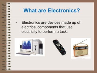
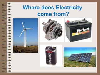
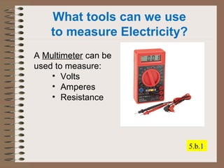
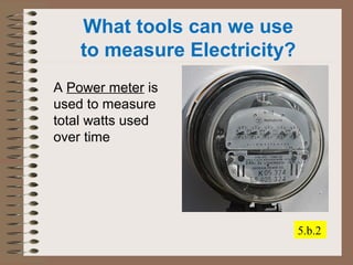
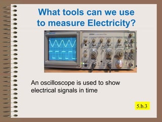
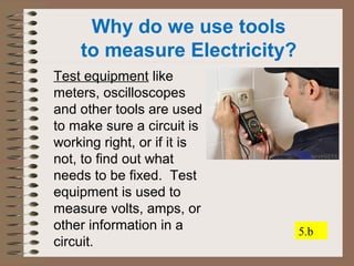
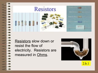
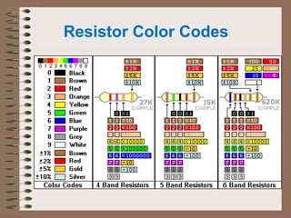
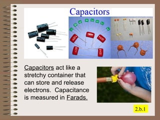
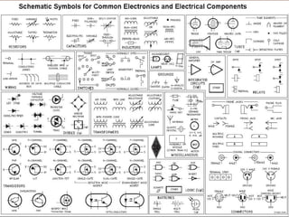
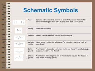
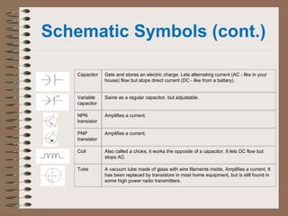
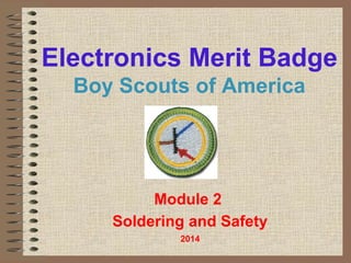
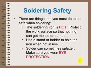
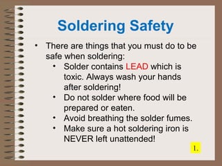
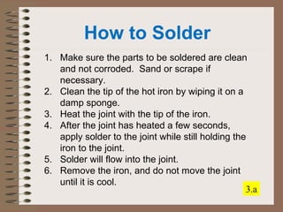
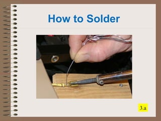
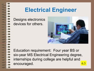

This document provides an overview of the Electronics Merit Badge module on electronic components and what they do. It defines electronics and electricity, discusses conductors and insulators, and how electricity is measured. It also describes common electronic components like resistors, capacitors, transistors, integrated circuits and their functions. Measurement tools like multimeters and their uses are explained. Finally, it provides an introduction to schematic diagrams and symbols.