SlideShare a Scribd company logo
With Source Code
CD ISSU
E
` 675/-
March / April 2015 Vol. 9 No. 2A Research Journal on Embedded Technology
EMBEDDEDForYou
www.embedded4u.comwww.embedded4u.com
G.M. COUNTERG.M. COUNTER
Pg. 11
Interfacing Hydrogen
Sensor
Pg. 11
Interfacing Hydrogen
Sensor
Pg. 8
Digital Fuel Gauge
Meter
Pg. 8
Digital Fuel Gauge
Meter
FREE
INSIDE
PCB
We invite you to participate in the incubation module which will offer a broader platform for
you in reaching out to each and every section of the Embedded Industry.
Sell your designs through Embedded ForYou.
Get your designs manufactured through our tie-ups to contract manufacturers.
Get recognized by getting your technical articles and research papers published through
Embedded ForYou.
We are capable of providing flexible and suitable product solutions from design to
manufacturing, through our tie-ups with renowned business associates and leading
manufacturing companies.
l
l
l
embedded4u@gmail.com
www.embedded4u.com
We are grateful to our readers for their tremendous response to Embedded For You
that gave us a readership of over One million in such a short span of time.
Automatika
Electronic
Bazaar
E-pulse Networking
Budding
Scientist
Techno
Focus
Envision
Master
Minds
EMBEDDED FOR YOU
100 U.B., Jawahar Nagar, Delhi - 110 007
Ph.: 011 - 42381979 E-mail: embedded4u@gmail.com Website : www.embedded4u.com
www.embedded4u.com
Dedicated to the Embedded World
4 Embedded For You March / April 2015
March / April 2015, Issue 2
Embedded For You
A journal on Embedded Technology
CONTENTS
Budding scientistS....................7
Departments
E-Entertainment.............................................................................6
In News.........................................................................................13
Electronic Bazaar...................................................................15-18
Techno Trendz........................................................................33-34
Calendar......................................................................................36
Organizations Covered..............................................................37
Jobs For You................................................................................37
E4U Highlight
2007, 08, 09, 10, 11,12,13,14....................................................38-40
E4U Subscription form.................................................................41
Circuit ideas
ISSN- 0973-791X
EDITORMANAGING DIRECTOR TECHNICAL ADVISOR ADVISORY BOARD
Harshita Gupta
embedded4u@gmail.com
Dr. Anshu Gupta
embedded4u@gmail.com
Divyansh Gupta
divyu.gups@gmail.com
DESIGN MANAGER
Kiran Bala
Ashok
J.P. Gupta
S. K. Gupta
100 U.B. Jawahar Nagar, Delhi - 110 007, Ph. : 09810543929
embedded4u@gmail.com
ADVERTISEMENTS & QUERIES
100 U.B. Jawahar Nagar, Delhi - 110 007, Mob.: 9810014979
advertise@embedded4u.com, embedded4u@gmail.com
SUBSCRIPTIONS AND MISSING ISSUES
Envision - I......................................................................................8
ESAT Lesson - 51........................................................................11
Digital Fuel Gauge Meter
Interfacing Hydrogen (H2) Sensor
Brain Teaser..................................................................................9
Smart Circuit - I...........................................................................10
DIGITAL FUEL GAUGE METER
Embedded For You
Embedded For You March / April 2015 5
Master MindS...........................19
Techno focuS..........................28
Networking
Automatica
E-Pulse
Bio-Buzz......................................................................................32
Circuit...........................................................................................29
Circuits..........................................................................................
Circuit...........................................................................................31
1 Ghz Millivoltmeter
Latest news and product updates in medical field
30
Independent M:S Adjustment For Wide - Band Pulse Gen
A Simple Charge Measuring Meter
Embedded For You is published bimonthly on the last day of second month. Views and opinions
expressed in this publication are not necessarily those of Academy of Embedded Technology.
Academy of Embedded Technology reserves the right to use the information published in this issue
whatsoever. While every effort has been made to ensure accuracy of the information published in
this edition, neither AET nor any of its employees accept any responsibility for any errors. No part of
this publication may be reproduced in any form without the written permission of the publisher. All
right reserved.
Printed and published by Sandeep Kumar Gupta. Printed at Goel Stationers, B-36/9, G.T. Karnal
Road Industrial Area, Delhi - 110 033, and published from 100-U.B., Jawahar Nagar, Delhi - 7.
Hardware Description of G.M. Counter.....................................25
Smart Circuits - II..........................................................................27
A Geiger counter (Geiger-Muller tube) is a device used for the detection
and measurement of all types of radiation: alpha, beta and gamma
radiation. .................................
G.M. Counter
R1
15k
Rem +15V Loc +15V
Loc +15V
Loc -15V
Rem = Remote Power
Loc = Local Power
Tr1
Vcc
GND
R3
2k2
R7
2k
R4
2k2
R5 11k
R6 10k
Tr2
Rem -15V
Rem 0V
Vin
R2
15k
D1
D2
IC1 6N136 IC2 AMP-02
Rg Rg
Vcc
Vout
Loc 0V
REFVee
-
+
You can send subscription amount to current Ac.No. ,
Kotak Mahindra Bank, Kamla Nagar, Delhi 110007
.
"EMBEDDED FOR YOU" 2611229474
IFSC : KKBK0000190,
Please inform by sending a letter to our office for future records
Envision - II.....................................................................................20
in continuation............
Please add Rs. /- for outside Delhi cheques
Please prefer DD & send payments only in favour of
100 .
EmbeddedFor You.
Period In India Overseas
One Year
Two Year
Three Year
125 US$
250 US$
350 US$
3,950/-
7,500/-
11,250/-
SUBSCRIPTION RATES
Kindly add Rupees 300 for Postal charges.
e-Entertainment
6 Embedded For You March / April 2015
harmonics, by adding a resistor of
about 1M2 from the negative rail to the
junction or R3 and R4.
It also seems that the quote frequency
of 800Hz was in error; the observed
Figure 1 frequency was 2340Hz,
approximately that at which the
reactance of C1 (=C2) is equal to the
COMMENTS ON “LOW DISTORTION OSCILLATOR”
The oscillator described can be
improved by making the second stage
gain greater than one, and taking the
output from the first stage rather than
the second. In Figure 1. the values of
R3 and R4 have been interchanged for
this purpose the preset resistor Rf then
needs to have approximately twice the
original value but there are no other
changes.
The limiting now takes place in the
second stage an the selectivity of the
first stage is available to filter the
resulting distortion. From an
oscilloscope comparison the setting of
Rf is considerably less critical than in
the original circuit about 96% of the
value required just to sustain oscillation
is a reasonable compromise between
waveshape compromise between
waveshape and start - up time.
A further improvement can be had by
making the stage 2 clipping symmetri-
cal, and so minimizing second
Fast Full-Wave Rectification circuit
idea is important tool for radio
communication engineers and
hobbyist in Loosely based on a design
in which current mirrors sensed the
supply current of op-amps, this circuit
uses a MAX435 wide - band,
differential output transconductance
amplifier to give full -wave rectification
of signals up to 250MHz. Output is 4Z /
V for the MAX435 IC. One can also try
the Burr-Brown OPA660, which offers
700MHz - pulse operation.
L
in
geometric mean of R1 and R2, as might
be expected.
The oscillator may be implemented
using only one op-amp, by applying
positive feedback from the output
terminal of the first op amp in the
original diagram. To its non-inverting
input, as in Figure 2.
220µF
C1
10n
C1
10n
Out
C2
10n
C2
10n
R1
1k
R1
1k
R6
1k
Figure 1. Figure 2.
R2
47k
R2
47k
R5
18k
RV1
5K
R4
47k
R3
33k
Amps
TL072
Rf
33k approx.
FAST FULL - WAVE RECTIFIER
V1+
V1-
Io+
Io-
MAX435
BUDDING SCIENTISTSBUDDING SCIENTISTS
A Segment Contrived For Students Includes an Esat Lesson Plan,
(Embedded System Application Training) Easy Projects and Circuits.
Log on to : www.aet-embedtech.com
Robotics Music & Audio Communication Digital Meter Research & Experiments Sensors
Contents .........Page.............................................................
Envision I........................................................................................8
Brain Teasers.................................................................................9
Digital Fuel Gauge Meter
Interfacing Hydrogen
Smart Circuit I..............................................................................10
ESAT Lesson................................................................................11
Logic Gates
Sensor
EnvisioN - I
8 Embedded For You March/ April 2015
amount of fuel that there is in a Bike.
Bike owners need to be particularly
aware of fuel level. Having a low
amount of fuel can hamper the Bike
performance and damage it in the long
run.
Good sensors are equipped with
microprocessors, measure the fuel
level in a high temperature environ-
ment, and are designed for fast, on
request delivery. Low power consum-
ption and easy calibration are other
distinguishing features. When properly
functioning, fuel level sensors warn
when refueling is required.
The connection between the sensor
and the Bike should be stable. A stable
connection reduces the probability of
getting false readings that may lead to
the Bike stopping in the middle of the
road if the vehicle has ran out of fuel.
Although the sensor may indicate the
right level of fuel, the indicator may go
haywire as it can't interpret the data.
Checking if the sensor is working is the
best way to prevent accidents due to
false information.
Since Float inside the tank has some
limitation of moment and shape of the
tank is not linear.
Wiring and Indicator
Limitation
Mostly Fuel gauges in your bike tells
only mpty, id and ull position. it
does not give a clear idea of fuel
purchased. suppose your Bike fuel tank
has fuel capacity of 15 liters. Now if you
purchase only 10 liters, than there is no
graduation on the indicator dial to
indicate the 10 liter fuel purchase .
Here we give you a idea to make digital
fuel indicator for your bike using AET
DPM kit and float type fuel sensor.
Float type fuel level sensor are
commonly use in bikes. It consist of
float mounted on moving arm of
potentiometer. These float sensor are
mounted in the tank where float is
inside the fuel and potentiometer is
outside the fuel.
The float in the fuel tank varies as per
fuel level in the tank and controls the
viper position from maximum to
minimum. When the tank is full the float
is at the top and the resistance of the
potentiometer is maximum. When fuel
tank is empty the float is at the bottom
and resistance is minimum. suppose
resistance of float sensor varies
between zero to 100 ohms depending
E M F
upon the float sensor type and its
maximum resistance. Since our battery
voltage is 12 volts DC, if we connect the
sensor to battery directly current flow
will be 120 mAapprox, which is high, we
can easily calculate using Ohms law ie
V = I x R
V = 12 DC Battery Voltage.
R = Resistance of Float Sensor.
I = Current in the Circuit 120mAapprox.
We should further reduce this current
otherwise battery will discharge early.
So we connect 10,000 ohms
resistance in series to Float Sensor, as
per circuit given.
A fuel level sensor informs about the
DIGITAL FUEL GAUGE METERDIGITAL FUEL GAUGE METER
Figure 1. Float Sensor connection diagram
Open
Float Sensor Digital Fuel Gauge
AET DPM KIT
12VBattery
10k
Wiper
Sensor Signal
GroundClosed
EnvisioN - I
Embedded For You March / April 2015 9
Brain Teasers
1. A few friends meet each morning for coffee. For one of them, it is the only cup of coffee all day. For another, it’s only
the first of eight cups. Zowie !
Your challenge is to figure out how many cups of coffee each person drinks per day, how sugar lumps they use per cup,
and whether or not they put in milk.
a. Jan uses three times as many lumps as the person who drinks four cups.
b. Three people, including the one who uses four lumps, use no milk.
c. The one who drinks 1 cup day (not Max) drinks his coffee black without sugar.
d. Doris uses both milk and sugar.
e. Max, who uses no milk, uses half as many sugars as the person who drinks twice as many cups as he does.
f. Boris drinks two more cups than Jan, but Jan uses two more sugars than Boris.
Figure 1. Digital Fuel Gauge using AET DPM Kit
Maxdrinks4cups,with2sugars,nomilk.
Dorisdrinks5cups,with1sugar,milk.
Blizzodrinks1cup,withnosugar,nomilk.
Jandrinks6cups,with6sugars,milk.
Borisdrinks8cups,with4sugars,nomilk.
Max
Doris
Blizzo
Jan
Boris
Cups Lumps of Sugar Milk
1 4 5 6 8 1 40 2 6 Yes No
AET DPM KIT
IC7107
PIN 31
PIN 30
1M
100n
Float Sensor
Open Battery 12V
10k
Wiper
Sensor Signal
GroundClosed
Smart circuitS-I
10 Embedded For You March/ April 2015
If you refer to the switching circuit for
the transistor you will see that the
output voltage is high (consider this as
1) when the input voltage is low
(consider this as 0). This is the basic
NOT gate - there is an output when
there is not an input.
Combinations of these switching
circuits can be made into logic gates
that will perform simple decisions within
a microprocessor. These logic gates
are the basis of all decisions within
computers and from now on we will
consider their effects rather then their
internal structure.
We will consider the following types of
logic gate:
(1) NOT gate - this gives an output 1 for
an input of 0.
(2) NOR gate - this gives an output 1
for neither of two inputs 1.
(3) OR gate - this gives an output 1 for
either of two inputs 1 and both
The switching action of a transistor
makes it especially suitable for use in
digital logic circuits where the output is
either 0 or 1 depending on the input.
Applications of such circuits are to :
a). Switch on a water pump on a hot
sunny day.
b). Sound an alarm if the pilot light of a
boiler went off.
c). Sound an alarm if a burglar stepped
on a pressure pad or shone his
torch.
d). Switch a light on if it was a cloudy
day.
e). Add two simple binary numbers
together.
f). Switch on a fan if a darkroom door
was shut and it was warm inside
All these things and indeed many more
can be done with ELECTRONIC
LOGIC CIRCUITS. These circuits are
ones that can make decisions. Different
decisions need different circuits.
LOGIC GATES
inputs 1.
(4) AND gate - this gives an output 1 for
both two inputs 1.
(5) NAND gate - this gives an output I
for either but not both of two inputs
1 or both inputs 0.
(6) EXCLUSIVE-OR - this gives an
output I for either but not both of two
inputs 1.
(7) EXCLUSIVE-NOR - this gives an
output 1 when both inputs are 0 or
1.
Because of its wide use in modern
digital electronics the NAND gate will
be considered as a basic building block
for a variety of logic circuits. In fact a
number of other logic gates can be
constructed from NAND gates as is
shown below. The circuit in Figure 1
shows how a NAND gate might be
constructed from discrete components,
although it would normally be in the
form of an integrated circuit.
R1 R2
+6V
F
0
A
B
NOT Input
1
0
1
Output
F
1
0
AND
Input
1
0
1
0
1
B
0
0
1
1
Output
B
0
0
1
1
NAND
Input
A
0
1
0
1
B
0
0
1
1
Output
F
1
1
1
0
OR
Input
A
0
1
0
1
B
0
0
1
1
Output
F
0
1
1
1
NOR
Input
A
0
1
0
1
B
0
0
1
1
Output
F
1
0
0
0
EXCLUSIVE
OR
Input
A
0
0
1
1
B
0
1
0
1
Output
F
0
1
1
0
EXCLUSIVE
NOR
Input
A
0
0
1
1
B
0
1
0
1
Output
F
1
0
0
1
ESAT Lesson-51
Embedded For You March / April 2015 11
below a certain threshold value and
are generally slow to respond. Like
these sensors, the placement of H2
sensors, within a volume will be
critical, as H2 is a very buoyant gas.
For H2 alarm sensors, the detection
range will likely be 0.5 to 4.0 percent
H2 in air, with a response time of
several seconds to tens of seconds.
Once a large-scale leak is detected,
the buoyant nature of hydrogen means
that it is easily dissipated, making it
ultimately a safer gas to use than
heavy flammable gases which tend to
settle.
In contrast to leak detection, explosive-
limit monitoring, H2 sensors are also
required to monitor H2 going into a fuel
cell. Technical challenges originate
from the multitude of potential
generation sources for the gas. These
challenges include H2 from reformers,
tanks, electrolysers, H2 storage
media, biomass and other storage
technologies.
Catalytic Bead Sensors consist of two
beads surrounding a wire operating at
high temperature (450°C). One bead is
passivated, so that it will not react
when it comes into contact with gas
molecules. The other is coated with a
catalyst to promote a reaction with the
gas.
The beads are generally placed on
separate legs of a Wheatstone bridge
Interfacing Sensors
Hydrogen (H2) Sensor
Necessity of Hydrogen Sensor.
Explain the working of .
Study of Applications of .
Interfacing Microcontroller to .
Hydrogen Sensor
Hydrogen Sensor
Hydrogen Sensor
After completing this section you should be able to :
circuit. When hydrogen is present,
there is no measurable effect on the
passivated bead, whereas there is a
significant effect on the catalyzed
bead. The increase in heat increases
the resistance in that leg of the
Wheatstone bridge circuit, which in
turn changes the bridge balance
signal, which is the sensor signal.
In terms of performance specifications,
catalytic bead technology is generally
used in the 1 to 5 percent H2 range.
The response times of the sensor
varies, ranging from 10 to 30 seconds
for full-scale response Semiconductor
Sensors. Solid state sensors utilizing
semiconducting oxides generally
operate at temperatures above
ambient. The electrical resistance of
the sensor material will also depend on
temperature, and also on the chemical
composition of the surrounding
atmosphere. These sensors do offer
fast response in the range of 0-
1000ppm H2, therefore are useful in
leak-detection applications on the end
of a sensor wand.
Hydrogen Field Effect Transistors
(HFET). By using palladium as the
gate material for a standard field effect
transistor, small changes in the
resistivity of the palladium produce
large changes in the current-voltage
characteristics of the FET.
This sensor technology works well in
Introduction
Hydrogen is emerging as a primary
fuel source to replace oil-based fuels.
Hydrogen-based fuel cells will be the
mechanism by which electrical energy
will be derived from the reaction of
hydrogen and oxygen gases within the
fuel cell to make water.
All fuel cells require two types of
sensors; the first monitors the quality
of the hydrogen feed gas, and the
second for leak detection.
Hydrogen leak-detection sensors must
detect over the general level of
ambient hydrogen levels, and in a
variety of environments.
Leak detection can be accomplished
by two types of sensors: one to detect
the leak and a second alarm sensor
with a set-point set at 50 percent of the
Lower Explosive Limit (LEL) of 4
percent hydrogen in air. The need for
leak detection is especially acute
where there is a large volume of
hydrogen consumed. For example, in
residential/stationary applications and
in automotive applications, where the
fuel cell sits in an enclosed volume.
The demands on the explosive-limit
sensors and the leak-detection
sensors are naturally different.
Explosive-limit sensors have similar
metrics to current domestic CO or fire
alarm sensors, in that they are
continuously on, do not need to sense
ESAT Lesson-51
12 Embedded For You March/ April 2015
elements at a nominally constant
temperature, thereby decoupling
thermal resistivity changes from those
changes occurring as hydrogen is
diffused into or out of the palladium
alloy lattice. mapping of the H2 field
can be done over long distances.
Sensitive material of MQ-8 Hydrogen
gas sensor is SnO2, which with lower
conductivity in clean air. When
hydrogen gas exists, the sensor's
conductivity gets higher along with the
the range of 50 to 1000ppm range of
H2. As a palladium-based sensor
technology, it functions independently
of the environment.
Sensors for Fuel Cells, Which
comprises a triple redundant palladium
alloy thin-film resistor and an HFET,
which offers six orders of magnitude in
hydrogen detection on a single chip.
In addition to the sensing elements,
the sensor also has embedded heater
circuits which keep the sensor
* adjust the value for best output
( ) PC6RESET
VCC
GND
1
7
8
(XTAL1) PB6
ATMega8L
(ADC5/SCL)PC5
(ADC4/SDA)PC4
(ADC3)PC3
(ADC2)PC2
(ADC1)PC1
(ADC0)PC0
28
27
26
25
24
+5V
Vc
-
23
9
10
(XTAL2) PB7
XTL
8MHz
C7
100mF
Figure 3. Basic Measurement of Hydrogen (H ) Level2
+5V
R
Set
*
TH
1k
GAS
H2 Sensor
2
5
6, 4
1, 3
+Ve
-Ve
V Heater
Keypad connection
C9
10 Fm
R2
8K2
+5V
C4
33pF
C5
33pF
C8
0.1 Fm
R L
RS RH
(MOSI/OC2) PB3
(MISO) PB4
16
17
18
15
(SCK) PB5
(OC1A) PB1
19
(SS/OC1B) PB2(RXD) PD0
(TXD) PD1
(INT0) PD2
(XCK/T0) PD4
(AIN0) PD6
(AIN1) PD7
(ICP1) PB0
2
3
4
6
12
13
14
+5V
16
+5V
1
Figure1. Typical Sensitivity Curve
Figure 2. Typical temperature / humidity
characteristics
1
Rs/Ro
Rs/Rso
(ppm)
100 1000 10000
1.9
1.7
1.5
1.2
1.1
0.9
0.1
0.5
-20 0 20 40 50-10 10 30
0.1
0.01
60%RH
30%RH
85%RH
H2
Air
Alcohol
CO
CH4
The ordinate is resistance ratio of the sensor (Rs/R0),
the abscissa is concentration of gases. Rs means
resistance in target gas with different concentration,
R0means resistance of sensor in clean air. All tests
are finished under standard test conditions.
The ordinate is resistance ratio of the sensor (Rs/Rso).
Rsmeans resistance of sensor in 1000ppm H2gas
under different tem. and humidity. Rso means
resistance of the sensor in 1000ppm H2gas under
20 /55%RH.℃
gas concentration rising. Users can
convert the change of conductivity to
correspond output signal of gas
concentration through a simple circuit.
Hydrogen gas sensor has high
sensitivity to hydrogen gas, also has
anti-interference to other gases.
The Figure 3 is the basic test circuit of
Hydrogen Sensor. While VRL is the
voltage of load resistance RL which is
in series with sensor. Vc supplies the
detect voltage to load resistance RL
and it should adopts DC power.
Interfacing with Microcontroller
When H2 percentage is high sensor
resistance changes, since constant
current is passed though the resistive
element, change resistance is
converted into change in voltage and it
is measured by by AD off micro-
controller and also temperature is
monitored using thermistor. See the
output characteristic of sensor and its
temperature dependency to calculate
the H2 concentration.
Embedded For You March / April 2015 13
In newS
Arrow has extended its IoT
portfolio with a TI SimpleLink
wireless MCU platform and is
stocking development kits to
help customers get into IoT.
The SimpleLink supports
communications protocols
including Bluetooth low
energy, ZigBee, 6LoWPAN, Sub-1 GHz and ZigBee RF4CE. There
are ready-to-use protocol stacks. SimpleLink has an ARM
Cortex–M3 core, Flash memory,ADC, peripherals, sensor controller
and built-in on-chip security.
AMD announced that the AMD
Embedded R-Series accele-
rated processing unit (APU),
previously codenamed “Bald
Eagle,” is powering the latest
set-back-box (SBB) digital
media players from Samsung
Electronics, Co., Ltd. With
high performance, low power, and broad connectivity, the new
Samsung SBB-B64DV4 is an ideal fit for demanding signage
applications that transform Samsung SMART Signage Displays
into inclusive digital tools for a wide range of business needs.
Stanford University has
produced an aluminium ion cell
with “no decay over hundreds of
cycles, even thousands of
cycles”, according to scientist
Ming Gong, yet it can be
charged in a minute. Key to long
life, according to a paper in
Nature (‘An ultrafast recharge-
able aluminium - ion battery‘), is using a three-dimensional
graphitic-foam for the cathode. In a study, it identified a few types
of graphite material that give us very good performance.”
Arrow kits for IoTAluminium ion battery hits thousands of cycles for grid storage
AMD Embedded R-Series APU Powers Samsung
Electronics’ Digital Signage Systems Microsemi has introduced a range of
radiation-tolerant FPGAs intended for
space applications requiring up
to 150,000 logic elements
and up to 300MHz of
system performance.
Typical uses for RTG4 include
remote sensing space payloads, such
as radar, imaging and spectrometry in
civilian, scientific and commercial applications. Other applications
include mobile satellite services (MSS) communication satellites, as
well as high altitude aviation, medical electronics and civilian nuclear
power plant control.
FPGAs for big space satellites
Fujitsu Laboratories Ltd.
announced the development
of Web OS technology that
automatically connects
smartphones, regardless of
operating system, to
peripheral devices and
sensors, and enables
integrated use with cloud
services. Conventionally, connecting peripheral devices to
smartphones, tablets, and other smart devices requires a
dedicated application on the smart device for each device, with
different versions for different OS.
M/A-COM Technology has developed a
650W gallium nitride (GaN) on silicon
carbide (SiC) HEMT pulsed power
transistor for L-band pulsed avionics
applications. The transistor is available
in standard flange or earless flange
packaging. Designated the MAGX-
000912-650L00/MAGX-000912-
650L0S, it is a gold metalised, internally
matched, GaN-on-SiC depletion mode RF power transistor.
Operating in the 960 to 1215MHz frequency range, the MAGX-
000912-650L0x is a rugged and robust transistor, boasting a mean
time to failure (MTTF) of 600 years.
Fujitsu Develops Web OS Technology GaN technology gives 650W power transistor
Seeking funding through
Indiegogo, Codie is a robot toy
that teaches the principles of
coding to children. Via a phone
app, the robot is moved by
simple drag-and-drop graphical
instructions that include:
variable, loops, branches and
sub-routines. Sensors on-
board measure distance,
acceleration and direction. “Kids control the Codie robot with a
touch-screen app featuring a visual coding language that
organises robotics code into action blocks.
Cypress Semiconductor is sampling a
USB Type-C cable controller which
includes power delivery (PD) on a small
footprint. It is designed for use in 2.4mm
thin USB Type-C cable connectors. The
programmable EZ-PD CCG2 controller
is capable of supporting any USB Type-
C downstream facing port (DFP) or
upstream facing port (UFP)
applications. It is available in a 3.3 mm2
wafer level chip scale package (WLCSP) and is notable for
integrating both the Type-C transceiver and termination resistors
needed for Type-C communication.
Microcontroller fits in a USB Type-C connectorKids robot teaches coding
TM
Siemens researchers have
developed a new type of electric
motor that, with a weight of just
50 kilograms, delivers a
continuous output of about 260
kilowatts – five times more than
comparable drive systems. The
motor has been specially
designed for use in aircraft.
Thanks to its record-setting
power-to-weight ratio, larger aircraft with takeoff weights of up to two
tons will now be able to use electric drives for the first time.
Toshiba has announced a new
ARM Cortex-M4F based
microcontroller for use in secure
systems control. Called
TMPM46BF10FG and part of the
firm’s TX04 range, it incorporates
a true random number generator
(TRNG: SP800-90C standard)
through a random entropy seed
generation (ESG) circuit and Hash-DRGB created by the secure
hash processor (SHA) and software program. It is intended for IoT
devices, energy management systems, sensors and industrial
equipment.
Tektronix has introduced the entry
level AFG1022 arbitrary / function
generator which is affordable for
educational institutions and
companies on a budget. Its
specifications are more impressive
t h a n s c o p e - b a s e d s i g n a l
generators. The dual-channel
generator has 25MHz bandwidth
with 1mVpp to 10Vpp output, 14-bit vertical resolution and 1µHz
frequency resolution. It provides a 125Msample/s sample rate along
with 64Mbyte of built-in non-volatile memory and USB memory
expansion for user-defined waveforms.
Nanotec of Germany has introduced a
42mm flange motor with integrated
controller and encoder. Called PD2-C,
it comes in two electro-magnetic
options: 12-48V stepper motor with
0.5Nm nominal torque, or brushless dc
(BLDC) motor with 105W nominal
output, peaking at 315W. Due to its
field-oriented control, the stepper motor
behaves like a high-pole DC servo –
with a higher torque but lower nominal speed than a BLDC motor.
Therefore many applications can be realised without a gear.
Printed electronics firm Thin Film
Electronics has developed a
near field communication (NFC)
sensor for tagging bottles which
can detect when a product is
“sealed” and “open”. Likely to be
used for tagging wine and spirits,
pharmaceuticals, cosmetics and
automotive fluids, the tag is designed to provide NFC-readability
before and after a factory seal on the product has been broken.
According to the Norway-based company, it is possible to provide
content to mobile devices on “sealed” or “opened” status, as the
consumer’s context shifts from “pre-purchase” to “in use.”
PCB DFM check service on artwork from any EDA tool set
NFC tag will provide product marketing information
Tektronix targets low cost sig gen at schools
NI’S New CompactDAQ Controllers
Small motor with integrated controller
Toshiba adds encryption to Cortex-M4F for IoT
In newS
14 Embedded For You March / April 2015
NI (Nasdaq: NATI), the
provider of platform-based
systems that enable engineers
and scientists to solve the
world’s greatest engineering
challenges, announced the
new Compact DAQ 8-slot
controller, which expands the CompactDAQ controller offering to
meet high-channel count applications in rugged environments. By
integrating the processor, signal conditioning and I/O into a single
CompactDAQ system, engineers can reduce overall system cost
and complexity while increasing measurement accuracy.
Anritsu has introduced the
ShockLine MS46121A series
of 1-port USB vector network
analysers (VNAs). Two models
with frequency coverage of
40MHz to 4GHz and 150kHz to
6GHz are powered and controlled by a PC through the USB port.
Sweeps can be conducted at 100 microseconds per point and the
MS46121A VNAs have a corrected directivity of 42dB so engineers
have greater measurement confidence. The MS46121A series is
controlled through software that provides the tools and graphical
user interface (UI) for debug and testing of 1-port RF devices. It also
provides remote programming capabilities.
USB-based 6GHz vector network analyser
World-record electric motor for aircraft
Winchester-based PCB design
house Professional Circuit
Designs (PCD) is offering
design for manufacture (DFM)
checks for Gerber and ODB++
files. PCD can also modify the
Gerber or ODB++ files to pass
DFM checks against ERFs
(electronic rules files) from
several PCB makers, giving the customer a choice of more than one
production site from a common data set.
MASTER MINDSMASTER MINDS
A Segment For Engineers Professional and Hobbyist,
Featuring Circuits and Embedded Projects.
Contents...........................................................Page
Envision II.........................................................................20
25
Smart Circuits II................................................................27
G.M. Counter
Hardware Description.
Fuse Replacement by Variable Semiconductor
.......................................................
Log on to : www.aet-embedtech.com
Communication Medical Electronics Home AutomationMusic & AudioRobotics Research & Experiments
EnvisioN-II
20 Embedded For You March /April 2015
Introduction
History - GM Detector
Physics principle behind GM Detector tube
Theory of Operation
AGeiger counter (Geiger-Muller tube) is a device used for the
detection and measurement of all types of radiation: alpha,
beta and gamma radiation. Thanks to an ingenious German
physicist named Hans Geiger, we've all heard the sound of
radioactivity. It's just as well we do have Geiger counters
because most radiation (radioactive particles and energy) is
extremely harmful to living things, completely invisible, and
very difficult to detect in other ways.
A "Geiger counter" usually contains a metal tube with a thin
metal wire (Figure 1.) along its middle; the space in between
them sealed off and filled with a suitable gas, and with the
wire at a very high positive electric potential relative to the
tube(a).
An electron, positive ion, or gamma radiation penetrating the
tube through a mica window, will ionize a number of the
atoms in the gas(b), and because of the high positive voltage
of the central wire, the electrons will be attracted to it while
the positive ions will be attracted to the wall(c). The high
voltage will accelerate the positive and negative charges,
they gain more energy and collide with more atoms to
release more electrons and positive ions; the process
escalates into an "avalanche" which produces an easily
detectable pulse of current. With a suitable filling gas, the
current quickly drops to zero so that a single voltage spike
occurs across the resistor R and that is registered by an
electronic counter. A scaler counts the current pulses, and
one obtains a”count” whenever radiation ionizes the gas
(Figure 2.).
As explained in the working principle of GM counter, the
collection of the charge thus produced results in the
formation of a pulse of voltage at the output of the tube. The
amplitude of this pulse, on the order of a volt or so, is
sufficient to operate the scaler circuit with little or no further
amplification.
G.M. COUNTERG.M. COUNTER
EnvisioN-II
Embedded For You March / April 2015 21
1. Plateau curve
2. Dead-time of the GM counter
Every GM tube has a characteristic response of counting rate
versus voltage applied to the tube. A curve representing the
variation of counting rate with voltage is called a plateau
curve (Figure 3). The counter starts counting at a point
corresponding approximately to the Geiger threshold
voltage; from there follows a “plateau" with little change in the
counting rate as the voltage increases. Finally a point is
reached where the self-suppressing mechanism no longer
works, and the counting rate rapidly increases until the
counter breaks down into a continuous discharge. In order to
ensure stable operation, the counter is operated at a voltage
corresponding approximately to the mid-point of the plateau.
Plug the Geiger-Müller tube into the scaler (counter) and
switch on.
Start the voltage at about 200 volts. Make a note of the
number of counts in, say, a 15 second interval.
Increase the voltage in steps of 25 volts.
You will find that the counts vary with voltage and then
reach a plateau. A graph would look like this (you do not
need to plot the graph):
After the threshold voltage, the count will reach a
plateau. It will stay constant over a range of voltages.
Set the voltage at a value of between 50 to 100 V above
the threshold.
If the clicking increases when you increase the voltage,
then you have moved off the plateau.
Turn the voltage back down.
Put the source back in a safe place until you carry out the
demonstration.
As determining the plateau is an important aspect, so is
determining the dead time.
Build-up of the positive ion space charges after each
discharge process turns the G-M tube off for the next incident
radiation measurement. A considerable amount of time
should elapse before next avalanche can take place in the
tube. Depending on the physical characteristics of the
Determining the Plateau :
l
l
l
l
l
l
l
l
l
Figure 1. The Geiger Counter
R
Voltage Spike
to Counter
Central Wire (+ Voltage)
Outer Cylinder (- Voltage)Mica
Window
a b g, , or
radiation
V
+
(a)
(d)
(e)
(e)
(b)
----------------------
+ + + ++ + + ++++
+ + + + ++ + + + + +
+
+
+
+
+
+
+
+
+
+
+
+
+
+
+
+
+
+
+
+
+
+
+
+
+
-
-
-
- - -
- ---
-
--
-
-
-
-
-+ + +
+
+
++
+
+ ++
+ + +
+ +
++
+
++
+
+
- +
Gm
Digital
Voltmeter
GM Tube
Source
Oscilloscope
Scaler Timer
High Voltage Supply
Figure 2. GM Counter block diagram
Figure 3. Geiger Tube Voltage Characteristics
Counting
Rate
Proportional
Discharge
Region
Geiger Plateau
Continuous
Discharge
Region
Applied
Voltage
Start
Voltage
Geiger
Threshold
Voltage
Operating
Voltage
V0
Geiger
Breakdown
Voltage
EnvisioN-II
22 Embedded For You March / April 2015
detector, this time is of the order of 20 to 300 s. This dead
period makes the G-M tube response as a nonlinear and
complicated function of the incident radiation intensity.
As it is visible from Figure 4. there is a time needed to process
the interaction and during that time, no further pulses will be
registered; this is known as the dead time or paralysis time.
Dead times range from a few µs for scintillation and the
smallest GM types to a few hundred µs for larger GM types.
The effect of dead time is shown in the figure below.
where = dead time of detector following an interaction
A total of 6 events occur within the detector (a) but only 4
counts are registered (b).
Events 3 and 5 will not be registered because they occur
during the dead time period of the detector.
Seeing the Operation Principle of GM Tubes, now we have a
fare idea of what features are required from a microcontroller
so that a prototype of a GM Counter can be made.
1) Minimizing DeadTime losses
2) Timer - Start and Stop Pulse counts
3) Boost Converter - 400V Power Source
4) Final Output – Counts Per Minute (uSV /Hours to CPM )
Dose Equivalent is measured in sievert (Sv) (Rem in the
U.S.)
Based on Atmega-328p and programmed with Arduino IDE.
In compare to other Arduino based Geiger counters on the
market, this product has reduced components amount that
makes this project very easy to solder.
The kit has basic simple function to count GM tube events
(CPM) and calculate gamma radiation DER for ambient
background level or for low-moderate radioactive samples.
Since it's educational Arduino IDE project, do not rely on its
readings in real hazardous situations !
The software and hardware where designed to produce tube
high voltage with PWM technology. No additional IC's
required, everything is controlled with software. By default it
programmed to 400V-420V and you can make fine adjust
through software calibration from 350V to 480V. If required,
the kit can be adjusted for 500V-550V. For higher voltage it
possible to make 600V hardware mode.
Complete design Schematic and Software code to make
your GM counter is provided in the Software CD. Following is
Explanation of GM counter construction
a. Generation of high voltage and biasing the GM tube.
b. Acquisition of raw analogue pulses from GM-tube.
c. Conditioning the raw pulses to form logic pulses.
d. Counting the logic pulses with time gating.
e. Display the counts per second or the dose information.
Generates a variable duty PWM signal using Timer1, to drive
the 400V inverter needed to operate the Geiger tube; The
invertor doesn't need a multiplier, as the ferrite's transformer
μ
τ
Effects of dead time on detector
GM Detector Board
Features of Microcontroller
Theory
Generation of High Voltage
Figure 4. Schematic of pulse train at high counting rates.
The discrimination level is set to 2V. Due to dead time effects,
some pulses do not cross the discrimination level, i.e. they
are not recorded as valid events.
5.5
5
4.5
4
3.5
3
2.5
2
1.5
1
0.5
0
PulseAmplitudeV
Time sm
Pulse Train and Their Losses
Fast portion of the G-M
detector pulse after
amplification block with a
rise time less than 1ms
2 V Discrimination Level
Due to dead time
effects, these pulses
are not recorded as
valid events
1000 200 300 400 500 600 700 800 900 1000
1 62
Event in detector
Event registered
t
43
a)
b)
5
1Event Number
Counted ? a
2
a
3
X
4
a
5
X
6
a
EnvisioN-II
Embedded For You March / April 2015 23
secondary puts out exactly the amount required. The
transformer is made on aA22 ferrite core, with 16 turns in the
primary and 600 in the secondary.
Figure 5 shows a simple boost converter which works on the
principle of fast switching of an inductor current between two
different levels. In the schematic shown, the switch is initially
closed for a long time and a constant current is established in
the inductor. Now, when the current is suddenly switched
from the established constant value to zero by opening the
switch a high voltage is generated on the pole side of the
switch.
This momentarily generates high voltage that can be stored
in a capacitor through a diode and further processed to act as
a source. Since any load connected to the capacitor
discharges it, the capacitor charge should be constantly
replenished by repetition of the switching action. This is done
by replacing the mechanical switch with a switching
transistor with a pulse signal in its base terminal. There is a
simple relation between the input voltage (Vin) and the output
voltage (Vout) of a boost converter in terms of the duty cycle
(D) which states.
The high voltage generated depends on the duty cycle of this
pulse signal.The duty cycle
), thereby enabling a current through the inductor to the total
cycle time, (There is the ratio of the time for which the switch
is kept closed (Ton + Toff), i.e., switch closed time added with
that time for which switch is open)
Thus, as the duty cycle approaches unity, output voltage
(Vout) that is greater than the input (Vin)
can be generated. This relation establishes that a constant
high voltage source can be realized using duty cycle control
of the switching transistor.
a. High voltage isolation
b. Overshoots due to sudden switching (inductive effect of
the central conductor).
These issues can be solved by the implementation of a
conditioning circuit as shown in Figure 3.
Then there is a voltage divider connected to the case of the
GM tube. This voltage divider is composed of 10K and 100K
resistors with a 220 pf bypass capacitor. Then there is a
voltage divider connected to the case of the GM tube. This
voltage divider is composed of 10K and 100K resistors with a
220 pf bypass capacitor.
The output of this voltage divider, which lowers the high
voltage pulse from the GM tube, is feed to an NPN transistor
which converts the analogue signal from GM-tube to form a
logic pulses.
As the conditioning of the logic pulses as now been done, it's
time to count the logic pulses.
d. Counting the logic pulses with time gating.
e. Display the counts per second or the dose information.
https://sites.google.com/site/diygeigercounter/gm-tubes-
supported
Duty Cycle
Precaution
Acquisition of raw analogue pulses from GM-tube
Conditioning the raw pulses to form logic pulses
Plan your Code
References
R1
4.7 Mohms
High Voltage
Analog Processing
* Buffer
* Comparator
Regulated Clamp Voltage
Regulated diode
drop compensation
Clamping network with overshoot clipping,
DC blocking etc..
Figure 5. Complete Clamping Circuit with overshoot protection and high voltage isolation
EnvisioN-II
24 Embedded For You March / April 2015
http://www.npl.co.uk/
https://www.cpp.edu/
http://physics.niser.ac.in/labmanuals/sem6/GM.pdf
https://www.cpp.edu/
// configure atmega IO
pinMode(LIGHT, OUTPUT); // turn on backlight
digitalWrite(LIGHT, HIGH);
pinMode(LED, OUTPUT); // configure led pin as output
digitalWrite(LED, LOW);
pinMode(2, INPUT); // set pin INT0 input for
capturing GM Tube events
digitalWrite(2, HIGH); // turn on pullup resistors
pinMode(BUTTON_UP, INPUT); // set buttons pins as
input with internal pullup
digitalWrite(BUTTON_UP, HIGH);
pinMode(BUTTON_DO, INPUT);
digitalWrite(BUTTON_DO, HIGH);
pinMode(A5, OUTPUT); // Set A5 as GND point for
buzzer
digitalWrite(A5, LOW);-starting tube high voltage------------
----------//
//----------------- load parameters--------------------//
#define RAD_LOGGER true // enable serial CPM
logging to computer for "Radiation Logger”
#define SMART_BL true // if true LCD backlight
controlled through ALARM level and key, else backlight is
always on
#define ACTIVE_BUZZER true // true if active 5V
piezo buzzer used. set false if passive soldered.
#define EEPROM_LOG true // if true will log
absorbed dose to eeprom every 60 minutes. Use only if
there is no Logging Shield available!
// install supplied libraries from lib.zip!
#include <Arduino.h>
#include <avr/pgmspace.h>
#include <EEPROM.h>
#include <LiquidCrystal.h>
#include <SPI.h>
#include "Configurator.h”
//-------------------------------------------------------//
//-----------------Define global project variables----------------//
unsigned long CurrentBat; // voltage of the battery
unsigned long counts; // counts counter
unsigned int countsHSecond; // half second counter
static unsigned long value[] = {0,0,0,0,0,0}; // array
variable for cpm moving algorithm
static unsigned long cpm; // cpm variable
static unsigned long rapidCpm; // rapidly changed cpm
static unsigned long minuteCpm; // minute cpm value for
absorbed radiation counter
static unsigned long previousValue; // previous cpm value
unsigned long previousMillis = 0; // millis counters
unsigned long previousMillis_bg = 0;
unsigned long previousMillis_pereferal = 0;
unsigned long previousMillis_hour = 0;
int n = 0; // counter for moving average array
long result; // voltage reading result
int buttonStateDo = 1; // buttons status
int buttonStateUp = 1;
unsigned int barCount; // bargraph variable
static float absorbedDose; // absorbed dose
static float dose; // radiation dose
static float minuteDose; // minute absorbed dose
boolean savedEeprom = false; // eeprom flag
boolean event = false; // GM tube event received, lets
make flag
//boolean limit = false; // absorbed dose limit flag
int cps_bar = BARGRAPH / 60; // fast bargraph
scale for cps
//-------------Roentgen/ Sieverts conversion factor--------------
--//
float factor_Rn = (FACTOR_USV * 100000) / 877; //
convert to roengten
float factor_Sv = FACTOR_USV;
float factor_Now = factor_Sv; // sieverts by defautl
int units; // 0 - sieverts; 1 - roentgen
//-----------------------------------------------------------------//
//-------------------Initilize LCD---------------------//
LiquidCrystal lcd(9, 4, 8, 7, 6, 5);
//----------------------------------------------------//
///////////////////////////////////////////////////////////////////////////////////////////
//------------------------------------------------------------------SETUP
AREA--------------------------------------------------------------------//
///////////////////////////////////////////////////////////////////////////////////////////
void setup()
{
// zero some important variables first
counts = 0;
countsHSecond = 0;
minuteCpm = 0;
minuteDose = 0;
n = 0;
cpm = 0;
EnvisioN-II
Embedded For You 25March / April 2015
Assembled Kit of G.M. Counter Kit can be purchased Online, Please contact: embedded4u@gmail.com
Hardware Description of G.M. Counter
+5V
T1
KSP44
T2
2N3904
C8
100µ
C11
300pF
C10
10nF
1000V
C9
100µL2
10mH
L1
P2
1K
R5
1K
R3
4.7M
R8
100R
D1
4937
D2
4937
R8
10K
+
Geiger
Tube
R9
100K
+5V
C1
100n
GND
TX
RST
VCC
RX
()RESETPC6
VCC
GND
7
8
PB6(XTAL1)
ATMega8L
(ADC3)PC3
(INT0)PD2
(OC1B)PB2
(ADC2)PC2
(ADC1)PC1
(ADC0)PC0
9
10
PB7(XTAL2)
X1
16MHz
C7
100mF
C4
10Fm
+5V
C5
22pF
C6
22pF
2
1
23
3
24
26
16
PB1(OC1A)
(RXD)PD0
(TXD)PD1
PD4(XCK/T0)
PB0(ICP1)
PD6(AIN0)
PD5(T1)
PD7(AIN1)
15
6
14
13
12
11
16
+5V
1
25
4
R11150E
R13150E
R4150E
R10
10K
R1
8K2
R12
10K
R7
1K
B_UPB_DN
+5V+5V+5V
+5V
T3
BC547
C2
1000Fm
REG1
7805
INOUT
GND
C3
100Fm
D8-12V.C.
+5V
PowerSupplySection
R2
4K7
D3
1N4007
ON
Smart circuitS-II
Embedded For You March 27/ April 2015
FUSE REPLACEMENT BY VARIABLE SEMICONDUCTOR
output at A. Monoshot 74121 has been
used to restrict any further pulses
coming from the previous op-amp
during ‘ON’ and ‘OFF’ time. An Ic7490
counter in 2 configuration has been
used to trigger the triac. Voltage drop
across 0.1 (high wattage) resistance
(which can be reduced or replaced by a
current meter) is fed to an amplifier in
the feed-back loop. The amplified
voltage is passed through a diode and a
parallel combination of 5 F and 10pF
capacitors which help in reducing the
transient (a high voltage drop across
0.1 due to heavy current at the time of
switching ‘ON’). The DC voltage
developed across the capacitors is fed
to the op-amp. As soon as the voltage
at pt B exceeds V , the output state of
the op-amp changes and trips ‘OFF’the
circuit. This circuit also senses the
¸
W
m
W
R
The circuit has been designed to
replace the fuses of high as well as low
current rating by a semi-conductor trip
system utilizing the triac of high as well
as low power rating. The current rating
of this S.C. fuse can be adjusted by
choosing a right value of the reference
voltage V of the feed-back loop and
hence a particular value of the fuse in
amperage can be set by a particular
value of reference voltage V . Thus the
same circuit can act as a fuse different
current rating. Initially, the high input
impedance of op-amp 741 which has
been exploited is in the order of 1M
as a tough switch. The impedance of
the human body being in the order of
500k and hence when the op-amp
741 is used in the comparator
configuration, a simple, touch of the
finger at ‘S’ will change the state of the
R
R
» W
»
W
voltage changes in the mains supply
efficiently. When the mains ac voltage
exceeds 220V rms, the given circuit
trips ‘OFF’the supply to load and hence
puts the triac to ‘OFF’stage.
The importance of the circuit lies in the
fact that it replaces the fuse which is a
consumable item. where as in this
circuit nothing is consumable and
therefore has a long life expectancy.
Moreover, the trip time is very small as
compared to the fusing time of the
fuses made until now. The trip time
decreases with the increases with the
increase of load current from the
designed fuse (in this case a S.C. fuse)
current. This would avoid damage of
costly and sensitive equipments either
due to voltage fluctuations or any short
circuit inside the equipment occurring
suddenly.
Vcc+5V
S
1.8k
2
3
3
2
3
2
B
7
7 7
4 4
6 6
4
6
A
1000µF
25V
2.5µf
10V
10µF
25V
5µF
25V
1µF
10µf
25V 10µf
25V
10µF
25V
0.22µF
10V
0.47µF
2.5µF
1.8k
1.8k
10k
100k
100W
LED
100W
0.1
or
(current
meter)
W
1.8k
3V
330k
5.6k
10pF
47k
VR
1k
56k
LOAD
220V / 50Hz (r.m.s.)
ST 044
4
14
3
5
14 12
5
7 2 6 7 10
11
74121
741
741
7490
10
TECHNO FOCUSTECHNO FOCUS
A Segment Pertains to the Arena of Automation,
Communication and Medical Sector
Contents Page.....................................................................
Networking
Circuits ................................................................................29
Automatika
Circuits ................................................................................30
E-Pulse
Circuits ................................................................................31
Bio-Buzz...............................................................................32
1 Ghz Millivotmeter
Independent M:S Adjustment For Wide - Band Pulse Gen
A Simple Charge Measuring Meter
Latest news and product updates in medical field
Log on to : www.aet-embedtech.com
NetworkinG
Embedded For You March / April 2015 29
1 GHZ MILLIVOLTMETER
Figure. 5. Complete circuit diagram.
C1
22n
C2
1n
C4
220n
C5 2n2
C9
22n
R14
10k
R12
2k2
1N4148
R11
15k C11
10µ
C10
47µ
M1
0-2V
R39
2k2
R4
1k
R7
15k
R8
330kR9
10k
R10
10k
R37
2k2
R36
2k2
R45
2k2
R30 6k8
R33
1k5
C23
2n2
R29
10k
R32
1k8
R31
10k
R34
2k2
R46 2k2
R35
2k2
C22
2n2
R41 2k2
R6
2k2
R5
2k2
R15
10k
R13
330k
R40 2k2
+Vs
+Vs
+Vs
-Vs
-Vs
-Vs
S1aC6
100p
Tr1
BC173C
C3
22n
C3
22n
C8 22n
5
6
4
D3
D4
R1*
-20
R2
390k
R3
1k
R38
10k
R47
1k8
L1
L2
2
6
D1
D2
--
++
-
-
+
+
-
-
-
+
+
+
2
3
A
3
2
3
2
3
2
1
2
6
5
11
12
10
6
1
6
7
B
+Vs
-Vs1
IC1
IC2
IC3a
IC3b
IC7LF356
LM311
IC8
IC9a
IC9b
IC9c
LM308A
CA3193
LM358
C12
2µ2
C13
10µ
C14 18p C21
2µ2
T1
C17
560p
C15
6n8 C18
6n8
C16
5n6 C19
5n6
C20
560p
R16
10k
R19
10k
R24
10k
R20
10k
R25
10k
R21
10k
R26
10k
R22 10k
R27 10k
R23 10k
R28 10k
R18
2k7
R17
8k2
R42
560
R43
560
R44
560
S1b
S1c
B
A
-
-
-
+
+
+
3
2
2
3
3
2
6
6
1
IC4
IC5
IC6
LM318
LF356
LF356
7
IC1 IC2 IC3
Decoupling 100n
IC4 IC5 IC6 IC7 IC8 IC9
4 44 4 4 74 44
7 8 7 7 7 7 8 14
+8V
-8V
The circuit diagram of the meter is
depicted in Fig.5. Error voltages is
first log. amplified (Ic1 in the probe),
then rectified (Ic2) and low pass
filtered (R4, C10). the following stage
(Ic3a, 3b) is a balanced to ground, low
output impedance d.c. amplifier.
Potentiometers R40, R41 null offsets
(zero meter indication with zero
rectifier input), balance is adjusted by
means of R39 although metering is
balance error free. The output of the
succeeding chopper, a b khz square
wave, is them amplified in meter
calibration amplifier Ic4. This stage
functions also as an impedance buffer
between chopper and the first active
filter. Separate calibration potentio-
meter, R42, R43, R44, are provided
for each subrange to compensate for
minor discrepancies in transformer T1
ratios. Two cascaded low pass
Butterworth active filters (Ic5, Ic6) that
follow, concert the square wave into a
sinusoidal voltage which, suitably
divided by switchable ratio
transformer T1(1:1, 10:1, 100:1), is
finally delivered to the comparison
detector in the probe. Auxiliary circuits
to switch to chopper comprise, 5KHz
frequency oscillator Ic7, shaper driver
Ic8 and inverter driver Ic9, R45 and
R46. To be continue.........
AutomatikA
30 Embedded For You March / April 2015
Independent m:s Adjustment for Wide - Band Pulse Gen
This circuit delivers square waves and
rectangular waves with a mark : space
ratio of 10 - 90 % at frequencies from
1.2kHz to 2.7MHz.
Frequency generation comes from the
voltage controlled oscillator Ic1 and
coming by way of the selector switch
from outputs Q1 - Q9, output
frequencies being 1/10 of the input from
Ic1, as in the square waveform from
carry output C0.
associated components., the output of
which is adjustable from 12KHz to
27MHz by means of the potentiometer.
Johnson counter Ic2 provides a Set
pulse from the Q0 output to the SR flip-
flop Ic3, the corresponding Reset pulse
1k5
15
-5V
6
7
14
13
15
2
3
1
5
6
Output Frequency
1.2KHz - 2.7KHz
4
3
2
4
7
10
1
5
6
9
11
12
0
1
2
3
4
5
6
7
8
9
CO
1
2
3
4
5
6
7
8
9
0
CLK
CLKEN
RST
VCO IN12P
IC3
HCT4046
IC2
HCT4017
VC OUT R1
9
4
3k3 3k3
A
B
C
D
E
Example shows waveforms for switch in position 3
Three Ics form a 1.2KHz - 2.7MHz pulse and square - wave generator having
a mark - to - space ratio adjustable in 10% steps from 10% to 90%
‘A’ ‘B’
‘C’
‘D’
‘E’
3 5 8 14
100k
e-pulse
Embedded For You March / April 2015 31
Simple Charge Measuring Meter
Experiments involving the manu-
facturing of optical waveguides by
electron beam irradiation on a glass
substrates, requires the accurate
measurement of electrical charge to
control the refractive index variation of
the substrate.
In the particular experiment of
incremental charge and accumulated
charge were required in increments of
0.001 Coulomb up to a total charge of
100,000 Coulombs. A further
requirement was to isolate requirement
was to isolate the meter circuit from the
measuring system.
A simple system for implementing the
Each time that an increment of charge
of 0.001 Coulomb builds up, the relay
is energized, discharging the 100µF
capacitor and the counter is
incremented. The system can be
calibrated by injecting a current of
100µA into the input and adjusting the
reference voltage so that the
monostable triggers repetitively at 0.1s
intervals.
Provision for zero offset control was
found to be necessary. However, figure
1 shows a zero offset control which is
adjusted for minimum update rate of
the display with the 100uF capacitor
disconnected.
requirements is shown in figure 1.
The applied charge in the form of an
electron beam causing current to flow
through the substrate is applied to Ic1,
functioning as an integrator with the
integrating capacitance of 100µF (10 x
10µF dielectric film). After buffering by
Ic2, the resulting ramp given by 1 x T/C
is compared to a 10V reference and an
edge is generated when the voltage
exceeds the reference causing the
monostable to trigger for approximately
10mS.
The pulse is coupled via opto isolator
IC6 to an 8 digit counter with built in
LCD display and to relay driverTr2.
10W
1k
10k
zero offset
10k
OV2
OV1
10k
15k 120k
.1
4k7 15k
15k
10k
Tr1 Tr2
10k 10k
15k
+12V
+15V
- 15V
6
5
3
2
6
4
4
8
2
2
3 5
8
IC6
6N135
6
3 5
6
4
1
1
7
1
100k
100k
Link
IC1
3140 IC2
3140 IC4
LM311
Hi
Lo
I/P
RLA
Discharge
10x10 fm
10V
Ref
IC3
REF.01CP
IC5
MC14538
Q
RLA
8 Digit
Counter
Bio BuzZ
32 Embedded For You March / April 2015
Better sensors for medical imaging, contraband detection
A team researchers used a
promising new material to
build more functional
memristors, bringing us
closer to brain-like
computing. Both academic
and industrial laboratories
are working to develop
computers that operate
more like the human brain. Instead of operating like a
conventional, digital system, these new devices could
potentially function more like a network of neurons. Concept
illustration (stock image). A new step forward in memristor
technology could bring us closer to brain-like computing.
Computers that mimic the function of the brain
High-tech method allows rapid imaging of functions in
living brain
Magnetic nanoparticles could allow brain stimulation
without wires
Researchers studying cancer
and other invasive diseases
rely on high-resolution
imaging to see tumors and
other activity deep within the
body's tissues. Using a new
high-speed, high-resolution
imaging method, Lihong
Wang, PhD, and his team at
Washington University in St.
Louis were able to see blood
flow, blood oxygenation, oxygen metabolism and other
functions inside a living mouse brain at faster rates than ever
before.
Researchers have developed
a method to stimulate brain
tissue using external magnetic
fields and injected magnetic
nanoparticles -- a technique
allowing direct stimulation of
neurons, which could be an
effective treatment for a variety
of neurological diseases,
without the need for implants
or external connections.Magnetic nanoparticles could allow
brain stimulation without wires.
The researchers
discovered that the
neural activity in the
quickest learners was
different from that of the
slowest. Their analysis
provides new insight into
what happens in the
brain during the learning
process and sheds light on the role of interactions between
different regions. The findings, which appear online today in
Nature Neuroscience, suggest that recruiting unnecessary
parts of the brain for a given task -- similar to overthinking the
problem -- plays a critical role in this important difference.
The brain game: How decreased neural activity may help
you learn faster
A new, ultrasensitive
magnetic-field detector
has been developed that
is 1,000 times more
energy-efficient than its
predecessors. It could
lead to miniaturized,
battery-powered devices
for medical and materials
imaging, contraband detection, and even geological
exploration. In this image, laser light enters a synthetic diamond
from a facet at its corner and bounces around inside the
diamond until its energy is exhausted. This excites "nitrogen
vacancies" that can be used to measure magnetic fields.
Swine flu outbreak in India raises concern: New strain of
H1N1 may carry dangerous mutations
Since December, an
outbreak of swine flu in
India has killed more
than 1,200 people, and a
new study suggests that
the strain has acquired
mutations that make it
more dangerous than
previously circulating
strains of H1N1 influenza. The findings, which appear in the
March 11 issue of Cell Host & Microbe, contradict previous
reports from Indian health officials that the strain has not
changed from the version of H1N1 that emerged in 2009 and
has been circulating around the world ever since.
Embedded For You March / April 2015 33
Techno trendZ
Allegro MicroSystems, LLC announces two new current sensor ICs that are economical and precise
solutions for AC or DC current sensing in industrial, automotive, commercial, and communications
systems. Allegro’s ACS724 (5 V) and ACS725 (3.3 V) are highly accurate devices with a very small
package. Both devices are ideal for space constrained applications that will save overall costs due to
reduced board area. Typical applications include motor control in automotive power braking
applications, oil and transmission pumps, or HEV charging circuits. Further information about Allegro
can be found at : .www.allegromicro.com
Allegro MicroSystems, LLC Announces New Current Sensor ICs with
Common Mode Field Rejection
Agilent Technologies Introduces Small, Reliable, Energy-Efficient Vacuum Pump
Cypress Expands Traveo Automotive MCU Family
New Microcontrollers Bring Advanced Graphics to Compact Vehicles; Backed by Spansion Automotive
Excellence and ServiceCypress Semiconductor Corp. (NASDAQ: CY) announced the expansion of its
Traveo™ microcontroller (MCU) family with a new series that provides automotive manufacturers with a
cost-effective platform to deliver 2-D and 3-D graphics and advanced functionality for dashboards,
head-up displays and HVAC systems in compact vehicles. The S6J32BA and S6J32DA series build
upon Spansion’s announcement of the Traveo 2-D graphics MCU S6J324C series and the 3-D graphics
MCU S6J326C series for midsize cars.To learn more, go to www.cypress.com.
Altera Corporation (NASDAQ: ALTR) and strategic IP partner Eutecus announce the availability of the
ReCo-Pro Multi-Channel High-Definition (HD) VideoAnalytics platform based on Eutecus’MVE™ video
and fusion analytics technology and Altera’s Cyclone® V SoC and Enpirion® PowerSoC devices.
Available from Eutecus, the ReCo platform has been chosen by Sensity Systems as the foundation for
adding intelligent vision processing to its high-speed, Light Sensory Network (LSN), which is currently
being installed in several US metropolitan areas. For more information on the products, contact
sales@eutecus.com.
Altera and Eutecus Single-chip, FPGA-Based Solutions “See” and Provide
Intelligent Vision for Smart Cities
Analog Devices, Inc., introduced a quad-channel, 2.4-GSPS, 16-bit D/A converter with industry leading
dynamic range performance in the 100- to 300-MHz band for complex IF transmitters. The highly
integrated AD9154 quad, 16-bit D/A converter is the only device of its kind to include an on-chip PLL
(phase-locked loop) and eight-lane JESD204B interface. The combination of features allows designers
to use a single device to meet all of their requirements in multicarrier GSM and LTE transmitters
designed for wireless macro base stations, point-to-point microwave radio, military radios and radio test
equipment. For more details visit at : .http://www.analog.com/AD9154
Industry’s Highest Dynamic-Range Quad, 16-bit D/A Converter Supports All Wireless
and Mobile Device Frequency Standards
Agilent Technologies Inc. extended its line of vacuum products with the compact new TwisTorr 84 FS
turbomolecular pump. Innovations in the TwisTorr 84 FS will extend performance, reliability and energy-
efficiency benefits to demanding academic and industrial applications. Such applications involve a
range of scientific instruments, from high-stability electron microscopes to high-throughput gas
chromatography/mass spectrometry systems. One of the pump's key innovations is its drag stage,
which guarantees high pumping speed and compression ratios for hydrogen and helium applications. It
also ensures high throughput, high foreline pressure tolerance, low power consumption and low
operating temperature. Information aboutAgilent is available at : .www.agilent.com
Intersil Announces Industry's First Fully Encapsulated 50A Digital Power Module
ROHM Co., Ltd. (TSE: 6963) has announced the production release of a dedicated system power
management integrated circuit (PMIC), the BD2613GW, to support the next generation, 14nm Intel®
Atom™ processor for tablets. A highly integrated power management solution with industry leading
power efficiency, ROHM's PMIC is targeted towards ultra-thin form factor tablets. This BD2613GW is a
successor PMIC to the BD2610GW which supports Intel’s current processor for tablets, the Intel Atom
processor Z3700 series. This new single-chip PMIC integrates all of the essential power FETs into same
WLCSPpackage as its predecessor, the BD2610GW.
34 Embedded For You March / April 2015
Techno trendZ
Intersil Corporation (NASDAQ: ISIL), a leading provider of innovative power management and precision
analog solutions announced the industry's first 50A fully encapsulated digital DC/DC PMBus power
module. The ISL8272M is a complete step-down power supply that delivers up to 50A of output current
from industry standard 12V or 5V input power rails, and four modules can be combined to support up to
200A rails. It provides point-of load conversions for advanced FPGAs, ASICs, processors and memory
in space-constrained and power-dense telecom and datacom applications. The device is also well
suited for high-end instrumentation, industrial and medical equipment. For more information about this
product please visit at : please visit at : .www.intersil.com/products/isl8272m
Texas Instruments (TI) (NASDAQ: TXN) introduced the industry's first cable driver to support
uncompressed 4K ultra high definition (UHD) video transmission using serial digital interface (SDI) and
10 gigabit Ethernet (GbE) protocols. The LMH1218 gives engineers the flexibility to design video
infrastructure equipment for SDI or Internet protocol (IP) formats with a single component. The
capabilities of the LMH1218 will be exhibited at the National Association of Broadcasters (NAB) Show,
April 11-16, in Las Vegas, Nevada. TI will offer product demonstrations in its booth, N8519. For more
information about the new LMH1218 cable driver. For more information about this product please visit at
: www.ti.com/lmh1218-pr.
TI delivers industry's first cable driver to support SDI- and IP-based 4K video
ROHM to start shipments of a Dedicated System Power Management IC for the 14nm
Intel® Atom™ processor for tablets
STMicroelectronics (NYSE: STM), has introduced new microcontroller chips designed to bring the same
high-performance graphics enabling intuitive smartphone-like user interfaces in the world of wearable
devices, smart appliances, and other IoT (Internet of Things) applications. The new STM32F469/479
microcontroller line delivers this new level of performance through the combination of ST’s Chrom-ART
Accelerator™1 and the MIPI-DSI technology2 that is widely deployed in today’s leading smartphones
and tablets, without higher cost or shorter battery-lifetime penalties. Further information on ST can be
found at : .www.st.com
Smartphone-Like Graphics Coming to Everyday Objects Courtesy of New
STM32 Microcontrollers from STMicroelectronics
Microchip Technology Inc., announced that the MOST® Cooperation released its MOST150 technology
coaxial physical layer specification. This new industry-standard specification enables Microchip to
support smart antenna module connectivity to in-vehicle MOST150 advanced driver assistance system
and infotainment networks, via its OS81118AF Intelligent Network Interface Controller (INIC) with
integrated coax transceiver. The MOST150 coaxial physical layer is ideally suited for smart-antenna
telematics and other data traffic from AM/FM, DAB, SDARS, DVB-T, 3G/LTE, GPS and Wi-Fi® signals
etc. For more information please visit at : .http://www.microchip.com/OS81118AF-032515a
Microchip’s MOST150 INICs Enable Cost-Effective Smart Antenna Module Coaxial
Connectivity to Automotive Control, Audio, Video and Internet Protocol Networks
®
TEST & MEASURING INSTRUMENTS
EXPERIMENTS & TRAINERS
Robotic Arm Trainer Fiber Optic Trainer
Microprocessor Kit Digital Trainer Kit
Development Kit 8051/AVR Automobile Electric System
PID Controller System Hall Effect Experiment
Oscilloscope Antenna Trainer
Microwave Optic System
Opto Electronics Lab
PC Based Instrumentation Lab
PCB Lab
Power & Industrial Electronic Lab
Refrigeration & Air Conditioning
Robotics Lab & CAD/CAM Lab
Agricultural Research Lab
B. Pharma Lab
Bio-Tech & Bio-Chemical Lab
Medical & Dental College Lab
Physics, Chemistry & Biology Lab
Vocational / I.T.I. Trade Labs
Industrial Electronics
Consumer Electronics
Computer Hardware
4
4
4
4
4
4
4
4
4
4
4
4
4
4
4
4
4
4
4
Nanotechnology Lab
Fiber Optic Lab
Misc. Cut Section & Test Rings
Applied Physics Lab.
Engineering / Polytechnic / Science College Labs :-
4
4
4
4
4
4
4
4
4
4
4
4
4
4
4
4
4
4
4
Advance Electronics Devices & App.
Analog, Digital & Data Communication
Physiotherapy & Paramedical Science
Audio, Video and Consumer Electronics
Automobile Engineering Lab
Bio Medical Electronics Instrumentation
Process Control & Instrumentation
Computer Software Engineering Lab
Digital Signal Processing Lab
Electrical Machine Lab
Embedded / Microcontroller Lab
Satellite, Wireless & Communication
Fluid Power & Mechanic Lab
Heat Transfer Lab
Laser Communication Lab
Mechanical Engineering Lab
Mechatronix Lab
Microprocessor Application Lab
Microwave Engineering Lab
ACADEMY OF EMBEDDED TECHNOLOGY
A-54/1, G. T. Karnal Road, Industrial Area, Delhi - 110 033
Ph.: 011 - 42381979, 9810014979 E-mail : aet.skg@gmail.com
Website : www.aet-embedtech.com
Academy of Embedded Technology
Our Corporate Mission
is a diversified product
development company, engaged in R&D Activities, training and design
development of various applications using embedded technology, AET was
established by Mr. S.K. Gupta having three decades of experience in
EmbeddedandElectronics.
With a reputation for engineering excellence, our greatest asset is our
talentedteamofhardwareandsoftwareprofessionals.
Rightfromitsinception,ourAETteamhasworkedconstantlytowardsthe
goal of increased quality and continuos technology updating. Our prowess in
Embedded Technology has earned us the status of Certified Third Party
ConsultantsoftheAtmelAVR.
l
l
l
l
To serve Educational Institutions with the latest technological
development
through our deep knowledge and long history in science education.
To guide the new generation for meeting the future needs of trade &
industry.
To bridge the gap between Academic courses & Industrial
requirement.
Skill Development in students using Embedded Application Training
and Embedded For You journal.
Foetal Doppler Transmission Line Demonstrator
CalendaR
36 Embedded For You March / April 2015
To register your event, please send us the details at : embedded4u@gmail.com, subscribe@embedded4u.com
Name, Date and Venue Events Links
Cruz Consultants Event Managers
Chingam, K. P. Vallon Road, Kadavanthra
Cochin, India
Foodtech Kerala is a 3 day event. This event showcases
product from Food & Beverage industry.
Foodtech Kerala
08 to 10 - May - 2015
CIAL Trade Fairs & Exhibition Centre, Cochin
Mex Exhibitions Pvt Ltd
9, LGF, Sant Nagar East of Kailash
New Delhi, India
The exhibitors will get a great platform to showcase their
products and services and launch new products and
designs that will be very beneficial for their company.
Led Expo Mumbai
07 to 09 - May - 2015
Bombay Convention & Exhibition Centre
Paramount Exhibitors
C-84, Industrial Area- VII, Mohali (Chandigarh)
Mohali, India
India International Cnc & Tooling Expo
09 to 11 - May - 2015
Punjab Trade Centre, Ludhiana
This event showcases product from Industrial Products,
Hand, Machine & GardenTools industries.
Paramount Exhibitors
C-84, Industrial Area- VII, Mohali (Chandigarh)
Mohali, India
Paramount Exhibitors
C-84, Industrial Area- VII, Mohali (Chandigarh)
Mohali, India
It will be throwing light on seven themes such as lab
instrumentation and equipment, lab automation,
software and hardware, lab and testing diagnostics,
labware and good lab practices.
This event showcases products like high power leds,
liquid leds, solar led lights, led components/ accessories
& raw materials, led encapsulation material, led
wafer/chips, led lighting and many more.
Lab Expo And Conferences
19 to 21 - June - 2015
NSIC Trade Centre - ECIL, Hyderabad, India
Led & Lighting Expo New Delhi
03 to 05 - July - 2015
NSIC Exhibition Complex, New Delhi
Smart Expos & Fairs (India) Pvt. Ltd
New No. 116, Old No. 81, Manickam Lane Mount
Road, Guindy, Chennai - 600 032, INDIA
This event showcases products like abrasive based
products, industrial robotics, cutting tools, die, pumps,
valves, to that of CNC machines associated with this
field etc.
Engineering and Machine Tools
19 to 21 - June - 2015
Chennai Trade Centre, Chennai, India
Paramount Exhibitors
C-84, Industrial Area- VII, Mohali (Chandigarh)
Mohali, India
India Trade Promotion Organization
Pragati Bhawan, Pragati Maidan
New Delhi, India
Paramount Exhibitors
C-84, Industrial Area- VII, Mohali (Chandigarh)
Mohali, India
Paramount Exhibitors
C-84, Industrial Area- VII, Mohali (Chandigarh)
Mohali, India
Led & Lighting Expo is a 3 day event. This event
showcases product from Electronics & Electrical Goods
industry.
This event showcases product from Electronics &
Electrical Goods industry.
This event showcases products like professional
educational institutes on engineering, management and
medical streams associated with this field etc.
This event showcases product from Electronics &
Electrical Goods industry.
Led & Lighting Expo
06 to 08 - June - 2015
NSIC Trade Centre - ECIL, Hyderabad, India
Electrical, Electronics & Energy Expo
06 to 08 - June - 2015
NSIC Trade Centre - ECIL, Hyderabad, India
Electrical, Electronics & Energy Expo
12 to 14 - June - 2015
Holly Hock Gardens, Jalandhar, India
Inter Ads
Plot No.859, Phase-V, Udyog Vihar,
Gurgaon, India
Renewable Energy World India
14 to 16 - May - 2015
Pragati Maidan, New Delhi, India
The show will focus to prevent useless wastage of
energy and will discuss about the effective mediums
which will help in protecting the power and energy.
Meraevents Versant Technologies Pvt. Ltd.
2nd Floor, 3 Cube Towers, Whitefield Road,
Kondapur Hyderabad, India
Mobile Expo
15 to 17 - May - 2015
Kasturchand Park, Nagpur, India
Paramount Exhibitors
C-84, Industrial Area- VII, Mohali (Chandigarh)
Mohali, India
Indian Machine Tool & Automation Expo Rudrapur
15 to 17 - May - 2015
ARK hotel, Rudrapur, India
Paramount Exhibitors
C-84, Industrial Area- VII, Mohali (Chandigarh)
Mohali, India
Tamil Nadu Energy Development Agency
5th Floor, E. V. K., Sampath Malligai, 68, College
Road Chennai, India
CODISSIA
G. D. Naidu Towers, P. B.No. 3827, Huzur Road
Coimbatore, India
Power, Electrical, Electronics & Instrumentation
21 to 23 - May - 2015
Nimantran Resorts, Baddi, India
Renergy
23 to 24 - May - 2015
Chennai Trade Centre, Chennai, India
Intec
05 to 09 - June - 2015
CODISSIA Trade Fair Complex, Coimbatore, India
This event showcases products like mobile based
products, telecom based products and services
associated with this field etc.
This event showcases product from Automotive,
Bicycles, Rickshaw & Spares, Hand, Machine & Garden
Tools, Minerals, Metals & Ores, Plant, Machinery &
Equipment, Business Services industries.
This event showcases product from Electronics &
Electrical Goods, Power, Renewable Energy & Energy
Conservation industries.
This event showcases product from Power, Renewable
Energy & Energy Conservation industry.
It will show machine tools and accessories, pumps and
fittings, foundry equipments, automation products,
instrumentation products, industrial consumables,
industrial electrical and electronic products etc.
Smart Expos
New No. 116, Old No. 81 Mount Road, Guindy,
Chennai, India
This event showcases product from Power, Renewable
Energy & Energy Conservation industry.
Solar South
19 to 21 - June - 2015
Chennai Trade Centre, Chennai, India
Professional Educational Fair
13 to 14 - June - 2015
Pragati Maidan, New Delhi, India
Subscription Application Form
We are grateful to our readers for their tremendous response to Embedded for you,
that gave us a readership of over one million in such a short span of time.
EMBEDDED FOR YOU
100 U.B. Jawahar Nagar, Delhi - 110 007 Tel.: 011 - 42381979
E-mail : Website :embedded4u@gmail.com www.embedded4u.com
Our DD/crossed cheque for Rs.______________________ bearing the No._______________________
drawn on (bank)________________________________ is enclosed in the favour of
payable at New Delhi.
Embedded For You
Yes I would like to subscribe for the term indicated below ( )
Please prefer DD & send payment only in favour of
Kindly add Rs. /- for outside Delhi cheques100 .
Embedded For You.
Subscription Period Starts only from January every year.
Signature : __________________ Date :___________________
Name :
Address :
City :
Mob:Phone :
E-mail :
Designation :
One Year
Period
Two Year
Rs. 4,250/- (6 Issues + 6 Project PCB)
Rates (Including Postal Charges)
Rs. 8,100/- (12 Issues + 12 Project PCB)
Overseas
125 US$
250 US$
350 US$Rs. 12,150/- (18 Issues + 18 Project PCB)Three Year
For Educational Institutes and Research Centres,
Industries and Embedded Electronics Community
Embedded For You Print Edition
After online transfer Please send us the proof of payment by Email / Post.
Account Name :
Bank Name :
Branch :
Account No.:
Type of Account :
IFSC Code :
Embedded For You
Kotak Mahindra Bank
Kamla Nagar, Delhi - 110007
2611229474
Current
KKBK0000190
Bank Details for online Payment :
Magazine
New Innovative Project with Free PCB
Source Code
PACKAGE INCLUDES
Now Available :
Pack of 9 Volumes for Rs. 26,500/-
With Source Code
CD Issue for E - Journals
Softwares with Source Code
Software Libraries Compatible
with Atmel Studio & CVAVR
Open Source Design files
and Schematic on Eagle CAD
Software, Hardware &
Programming using Arduino IDE
Industrial Electronic Projects in Volume Pack
ESAT Jumbo
Neuro Scope
eWA - IOT based Water Tank Control
NTC / PAL TV Kit
ESAT - ISP
Accelerometer (ESAT-ADXL335 Kit)
Embedded VGA Controller
Solar Battery Charger
Multi-Axis Stepper Motor Control
Mind Pulse
Mechatronic Trainer
Home Automation (2051 IO Board)
Voice Recognition Kit
Universal Remote Control
Light Auto Saver
GPS Logger
Music MIMIC
Industrial Timer / Clock
USB Host Shield
MIDI
DIY - Digital Panel Meter
Thermo Cam Bot
Traffic Light Controller
G.M. Counter
Dialogic System
Auto Tap Controller
DIY - Digital Panel Meter
Digital FM Radio Kit
Zigbee Evaluation Board
Smart Circuit Breaker Smart Curtain Control
Fundo Inventor Kit
Voltage Stablizer
Colour Analyser
USB HID Gamepad
TFT LCD Touch Controller 8051 Eval. Kit 8051 Quad Motor DriverPOV Display Railway Announcer Moving Message Display
Capsense Board
Includes :
56 Embedded Projects
51 Project PCBs + CDs
Target Readers
Ø
Ø
Ø
Ø
Ø
Ø
R & D Engineers of Private
and Government
Organizations.
Industry’s Decision Makers.
IC & Electronics Component
Distributors and Suppliers.
Electronic Product
Manufacturing Companies.
Electronic Engineers and
Hobbyists.
Engineering Colleges and
Educational Institutes.
Embedded For You is India’s First Magazine/Journal dedicated to the Embedded Industry. It is a Bimonthly
magazine published by Academy of Embedded Technology having more than to decades of experience in
Embedded Systems and Microcontrollers. Embedded For You is the most trusted source reference of CEO,
decision makers, business leaders, students scientists, hobbyist & technology heads in this field. It aids technical
awarenessandbusinessthroughuptodateknowledgeofindustryandtechnologytrends.
Create awareness in the Embedded Field
Provide well-trained man power to the Embedded Industry
Electronic Bazaar
The complete source for al you Electronic needs
ElectronicBazaarisacomplete sourceforallyouelectronicsneed-beitRobotic,Embeddeddevelopmentkit,Ics,basic
electronic components and equipment or security systems. We also provide services ranging form PCB designing to
prototyping.
Booking your space in Electronic Bazaar is not just another advertisement, it will add your product in out compiled list
ofproductcategorieswhichcaterstomorethan1millionconsumersalloverthecountry.
EMBEDDED FOR YOU
100 U.B., Jawahar Nagar, Delhi - 110007 Ph.: 011 - 42381979
Email : website :embedded4u@gmail.com www.embedded4u.com
OUR VISION
Terms and Conditions
Product photo
Brief specification
Price of the products
To Join us, Log on to : www.aet-embedtech.com
Email : divyansh@aet-embedtech.com | Contact Us : 9711967803
INNOVATE IMPLEMENT
LEARNCONNECT
Team E4U gives you an opportunity to
network with industry professionals,
engineers, students and hobbyists. Share
your ideas and in turn learn from our vast
knowledgebank.
We provide you a platform to learn and
increase your knowledge in Embedded
Systems development. Our training team is
always there to assist you resolve your
queries.
Our latest infrastructure and Embedded
labs have been designed to cater the needs
of young enthusiasts like you. You can use
our infrastructure to implement your
innovative idea and make an industrial
We have a hundreds of industrial
applications and projects already created to
help you in your own innovation. Use this
vast project bank and create your own
product.
Academy of Embedded Technology
LEARN . MAKE . SHARE
Team E4U provides a playground for engineers and hobbyists who want
learn, invent new ideas, innovate and implement them in the real
world.
We are a bunch of individuals who have formed an Embedded Centre
for learning. We have a team of engineers, industry professionals,
students and hobbyists with us who are enthusiastic about teaching,
resolvingyourEmbeddedproblemsandcreatingnewproducts.
We have the infrastructure for you to innovate almost anything you
RNI No. DELENG/2006/18319 Published on last day of the month
Intelligent Controllers for your Hardware / Software Solutions using
Embedded Technology
We Provide Solutions to Your Electronic Business
• Hardware / Software solution in Embedded Design Hardware / Software Solution in Power Electronics
Non-Destructive Testing (Process Control - Inspection Equipment) Training Equipment & Laboratory Experiments
Test & Measuring Instruments Medical Electronics & Hospital Equipments
Image Analysis and Microscopic Measurement Analytical Instruments & Laboratory Equipments
PC-Based Scientific Instrument Interface PC-based Industrial Automation
Industrial and Educational Robots Process Control Systems
Smart Card Based Solutions SPMs & CNC Machines and Controllers
•
• •
• •
• •
• •
• •
• •
Our Domains Areas :
ACADEMY OF EMBEDDED TECHNOLOGY
A-54/1, G. T. Karnal Road, Industrial Area, Delhi - 110 033
Ph.: 011 - 42381979, 9810014979 E-mail : aet.skg@gmail.com
Website : www.aet-embedtech.com
A
CONSULTANT
PROCESS AUTOMATION &
SPMS FOR INDUSTRIES
MEDICAL & HEALTHCARE
EMBEDDED SYSTEMS TRAINING
POWER ELECTRONICS &
HOME APPLIANCES
SAFETY & SECURITY SYSTEMS

More Related Content

What's hot

Serial Communication in 8051
Serial Communication in 8051Serial Communication in 8051
Serial Communication in 8051
Sudhanshu Janwadkar
 
IOT-Network Management.pptx
IOT-Network Management.pptxIOT-Network Management.pptx
IOT-Network Management.pptx
V.V.Vanniaperumal College for Women
 
Temperature monitoring and controling using arduino
Temperature monitoring and controling using arduinoTemperature monitoring and controling using arduino
Temperature monitoring and controling using arduino
Bablu Singh
 
Iot and Healthcare ppt
Iot and Healthcare pptIot and Healthcare ppt
Iot and Healthcare ppt
Armaan Farshori
 
A Report on Bidirectional Visitor Counter using IR sensors and Arduino Uno R3
A Report on Bidirectional Visitor Counter using IR sensors and Arduino Uno R3A Report on Bidirectional Visitor Counter using IR sensors and Arduino Uno R3
A Report on Bidirectional Visitor Counter using IR sensors and Arduino Uno R3
Abhishekvb
 
Rfid security access control system
Rfid security access control systemRfid security access control system
Rfid security access control system
Edgefxkits & Solutions
 
The future of IOT
The future of IOTThe future of IOT
The future of IOT
Arti Parab Academics
 
KAREL DS200 & EXCHANGES
KAREL DS200 & EXCHANGESKAREL DS200 & EXCHANGES
KAREL DS200 & EXCHANGESRaaman Pillay
 
Sensor interfacing in 8051
Sensor interfacing in 8051Sensor interfacing in 8051
Sensor interfacing in 8051
Irfan Ahmad
 
Voice Based Home Automation
Voice Based Home AutomationVoice Based Home Automation
Voice Based Home AutomationSumukh Athrey
 
Internet of things
Internet of thingsInternet of things
Internet of things
Shahneel Siddiqui
 
Digital to Analog Converter by LDCE students
Digital to Analog Converter by LDCE studentsDigital to Analog Converter by LDCE students
Digital to Analog Converter by LDCE studentsMitul Lakhani
 
IoT in Healthcare: How Internet of Things (IoT) is Revolutionizing the Medica...
IoT in Healthcare: How Internet of Things (IoT) is Revolutionizing the Medica...IoT in Healthcare: How Internet of Things (IoT) is Revolutionizing the Medica...
IoT in Healthcare: How Internet of Things (IoT) is Revolutionizing the Medica...
PritiranjanMaharana1
 
Challenges and application of Internet of Things
Challenges and application of Internet of ThingsChallenges and application of Internet of Things
Challenges and application of Internet of Things
Ashutosh Bhardwaj
 
PREPAID ENERGY METER USING SMART CARD
PREPAID ENERGY METER USING  SMART CARD PREPAID ENERGY METER USING  SMART CARD
PREPAID ENERGY METER USING SMART CARD
Athul Vinoy
 
Smart shopping trolley using rfid and remote controlling report
Smart shopping trolley using rfid and remote controlling reportSmart shopping trolley using rfid and remote controlling report
Smart shopping trolley using rfid and remote controlling report
Pranav Veerani
 
Ppt Digital Electronics
Ppt Digital ElectronicsPpt Digital Electronics
Ppt Digital Electronics
Naval Kush
 
Internet of things (IoT)- Introduction, Utilities, Applications
Internet of things (IoT)- Introduction, Utilities, ApplicationsInternet of things (IoT)- Introduction, Utilities, Applications
Internet of things (IoT)- Introduction, Utilities, Applications
Tarika Verma
 
Internet of things (IOT) Presentation-PPT
Internet of things (IOT) Presentation-PPTInternet of things (IOT) Presentation-PPT
Internet of things (IOT) Presentation-PPT
Charan Vimala
 

What's hot (20)

Serial Communication in 8051
Serial Communication in 8051Serial Communication in 8051
Serial Communication in 8051
 
IOT-Network Management.pptx
IOT-Network Management.pptxIOT-Network Management.pptx
IOT-Network Management.pptx
 
Temperature monitoring and controling using arduino
Temperature monitoring and controling using arduinoTemperature monitoring and controling using arduino
Temperature monitoring and controling using arduino
 
Iot and Healthcare ppt
Iot and Healthcare pptIot and Healthcare ppt
Iot and Healthcare ppt
 
A Report on Bidirectional Visitor Counter using IR sensors and Arduino Uno R3
A Report on Bidirectional Visitor Counter using IR sensors and Arduino Uno R3A Report on Bidirectional Visitor Counter using IR sensors and Arduino Uno R3
A Report on Bidirectional Visitor Counter using IR sensors and Arduino Uno R3
 
Rfid security access control system
Rfid security access control systemRfid security access control system
Rfid security access control system
 
The future of IOT
The future of IOTThe future of IOT
The future of IOT
 
automatic room light controller
automatic room light controllerautomatic room light controller
automatic room light controller
 
KAREL DS200 & EXCHANGES
KAREL DS200 & EXCHANGESKAREL DS200 & EXCHANGES
KAREL DS200 & EXCHANGES
 
Sensor interfacing in 8051
Sensor interfacing in 8051Sensor interfacing in 8051
Sensor interfacing in 8051
 
Voice Based Home Automation
Voice Based Home AutomationVoice Based Home Automation
Voice Based Home Automation
 
Internet of things
Internet of thingsInternet of things
Internet of things
 
Digital to Analog Converter by LDCE students
Digital to Analog Converter by LDCE studentsDigital to Analog Converter by LDCE students
Digital to Analog Converter by LDCE students
 
IoT in Healthcare: How Internet of Things (IoT) is Revolutionizing the Medica...
IoT in Healthcare: How Internet of Things (IoT) is Revolutionizing the Medica...IoT in Healthcare: How Internet of Things (IoT) is Revolutionizing the Medica...
IoT in Healthcare: How Internet of Things (IoT) is Revolutionizing the Medica...
 
Challenges and application of Internet of Things
Challenges and application of Internet of ThingsChallenges and application of Internet of Things
Challenges and application of Internet of Things
 
PREPAID ENERGY METER USING SMART CARD
PREPAID ENERGY METER USING  SMART CARD PREPAID ENERGY METER USING  SMART CARD
PREPAID ENERGY METER USING SMART CARD
 
Smart shopping trolley using rfid and remote controlling report
Smart shopping trolley using rfid and remote controlling reportSmart shopping trolley using rfid and remote controlling report
Smart shopping trolley using rfid and remote controlling report
 
Ppt Digital Electronics
Ppt Digital ElectronicsPpt Digital Electronics
Ppt Digital Electronics
 
Internet of things (IoT)- Introduction, Utilities, Applications
Internet of things (IoT)- Introduction, Utilities, ApplicationsInternet of things (IoT)- Introduction, Utilities, Applications
Internet of things (IoT)- Introduction, Utilities, Applications
 
Internet of things (IOT) Presentation-PPT
Internet of things (IOT) Presentation-PPTInternet of things (IOT) Presentation-PPT
Internet of things (IOT) Presentation-PPT
 

Similar to Embedded For You - Online sample magazine

IRJET - Expansion of Logic Gates using Trainer
IRJET - Expansion of Logic Gates using TrainerIRJET - Expansion of Logic Gates using Trainer
IRJET - Expansion of Logic Gates using Trainer
IRJET Journal
 
MODULE TITLE PROGRAMMABLE LOGIC CONTROLLERSTOPIC TITLE.docx
MODULE TITLE    PROGRAMMABLE LOGIC CONTROLLERSTOPIC TITLE.docxMODULE TITLE    PROGRAMMABLE LOGIC CONTROLLERSTOPIC TITLE.docx
MODULE TITLE PROGRAMMABLE LOGIC CONTROLLERSTOPIC TITLE.docx
roushhsiu
 
Apr9600 voice-recording-and-playback-system-with-j
Apr9600 voice-recording-and-playback-system-with-jApr9600 voice-recording-and-playback-system-with-j
Apr9600 voice-recording-and-playback-system-with-j
icstation
 
IRJET- Data Acquisition using Tensile Strength Testing Machine
IRJET- Data Acquisition using Tensile Strength Testing MachineIRJET- Data Acquisition using Tensile Strength Testing Machine
IRJET- Data Acquisition using Tensile Strength Testing Machine
IRJET Journal
 
Drowsiness Detected For Vehicle Using Smart Glass With Eye Blink Sensor
Drowsiness Detected For Vehicle Using Smart Glass With Eye Blink SensorDrowsiness Detected For Vehicle Using Smart Glass With Eye Blink Sensor
Drowsiness Detected For Vehicle Using Smart Glass With Eye Blink Sensor
IRJET Journal
 
RF Controlled Robot Using Advanced Sensors
RF Controlled Robot Using Advanced SensorsRF Controlled Robot Using Advanced Sensors
RF Controlled Robot Using Advanced Sensors
IRJET Journal
 
IMPLEMENTING A DIGITAL MULTIMETER
IMPLEMENTING A DIGITAL MULTIMETERIMPLEMENTING A DIGITAL MULTIMETER
IMPLEMENTING A DIGITAL MULTIMETER
Vijay Elavunkal
 
Implementation of 4-bit R-2R DAC on CADENCE Tools
Implementation of 4-bit R-2R DAC on CADENCE ToolsImplementation of 4-bit R-2R DAC on CADENCE Tools
Implementation of 4-bit R-2R DAC on CADENCE Tools
journal ijrtem
 
How to design a Passive Infrared (PIR) Open Source Project
How to design a Passive Infrared (PIR) Open Source ProjectHow to design a Passive Infrared (PIR) Open Source Project
How to design a Passive Infrared (PIR) Open Source Project
Ionela
 
Research Inventy : International Journal of Engineering and Science
Research Inventy : International Journal of Engineering and ScienceResearch Inventy : International Journal of Engineering and Science
Research Inventy : International Journal of Engineering and Scienceresearchinventy
 
IRJET- Piezo as Vibration Sensor using Amplifier Circuit
IRJET- Piezo as Vibration Sensor using Amplifier CircuitIRJET- Piezo as Vibration Sensor using Amplifier Circuit
IRJET- Piezo as Vibration Sensor using Amplifier Circuit
IRJET Journal
 
IRJET-Piezo as Vibration Sensor using Amplifier Circuit
IRJET-Piezo as Vibration Sensor using Amplifier CircuitIRJET-Piezo as Vibration Sensor using Amplifier Circuit
IRJET-Piezo as Vibration Sensor using Amplifier Circuit
IRJET Journal
 
IRJET - IoT based Gas Level Detection and the Automatic Booking of the Gas
IRJET - IoT based Gas Level Detection and the Automatic Booking of the GasIRJET - IoT based Gas Level Detection and the Automatic Booking of the Gas
IRJET - IoT based Gas Level Detection and the Automatic Booking of the Gas
IRJET Journal
 
IRJET- Performance Evalution of Gate Diffusion Input and Modified Gate Di...
IRJET-  	  Performance Evalution of Gate Diffusion Input and Modified Gate Di...IRJET-  	  Performance Evalution of Gate Diffusion Input and Modified Gate Di...
IRJET- Performance Evalution of Gate Diffusion Input and Modified Gate Di...
IRJET Journal
 
IRJET- Items’ Filling System Prototype with Sorting System According to the C...
IRJET- Items’ Filling System Prototype with Sorting System According to the C...IRJET- Items’ Filling System Prototype with Sorting System According to the C...
IRJET- Items’ Filling System Prototype with Sorting System According to the C...
IRJET Journal
 
IRJET - PLC based Temperature Controlling using Peltier Element for Industria...
IRJET - PLC based Temperature Controlling using Peltier Element for Industria...IRJET - PLC based Temperature Controlling using Peltier Element for Industria...
IRJET - PLC based Temperature Controlling using Peltier Element for Industria...
IRJET Journal
 
IRJET- Simulation and Performance Estimation of BPSK in Rayleigh Channel ...
IRJET-  	  Simulation and Performance Estimation of BPSK in Rayleigh Channel ...IRJET-  	  Simulation and Performance Estimation of BPSK in Rayleigh Channel ...
IRJET- Simulation and Performance Estimation of BPSK in Rayleigh Channel ...
IRJET Journal
 
Design & implementation of 16 bit low power ALU with clock gating
Design & implementation of 16 bit low power ALU with clock gatingDesign & implementation of 16 bit low power ALU with clock gating
Design & implementation of 16 bit low power ALU with clock gating
IRJET Journal
 
SolAero Tech Intern_Project Overview
SolAero Tech Intern_Project OverviewSolAero Tech Intern_Project Overview
SolAero Tech Intern_Project OverviewEddie Benitez-Jones
 
Speed control of single phase induction motor by android bluetooth
Speed control of single phase induction motor by android bluetoothSpeed control of single phase induction motor by android bluetooth
Speed control of single phase induction motor by android bluetooth
IRJET Journal
 

Similar to Embedded For You - Online sample magazine (20)

IRJET - Expansion of Logic Gates using Trainer
IRJET - Expansion of Logic Gates using TrainerIRJET - Expansion of Logic Gates using Trainer
IRJET - Expansion of Logic Gates using Trainer
 
MODULE TITLE PROGRAMMABLE LOGIC CONTROLLERSTOPIC TITLE.docx
MODULE TITLE    PROGRAMMABLE LOGIC CONTROLLERSTOPIC TITLE.docxMODULE TITLE    PROGRAMMABLE LOGIC CONTROLLERSTOPIC TITLE.docx
MODULE TITLE PROGRAMMABLE LOGIC CONTROLLERSTOPIC TITLE.docx
 
Apr9600 voice-recording-and-playback-system-with-j
Apr9600 voice-recording-and-playback-system-with-jApr9600 voice-recording-and-playback-system-with-j
Apr9600 voice-recording-and-playback-system-with-j
 
IRJET- Data Acquisition using Tensile Strength Testing Machine
IRJET- Data Acquisition using Tensile Strength Testing MachineIRJET- Data Acquisition using Tensile Strength Testing Machine
IRJET- Data Acquisition using Tensile Strength Testing Machine
 
Drowsiness Detected For Vehicle Using Smart Glass With Eye Blink Sensor
Drowsiness Detected For Vehicle Using Smart Glass With Eye Blink SensorDrowsiness Detected For Vehicle Using Smart Glass With Eye Blink Sensor
Drowsiness Detected For Vehicle Using Smart Glass With Eye Blink Sensor
 
RF Controlled Robot Using Advanced Sensors
RF Controlled Robot Using Advanced SensorsRF Controlled Robot Using Advanced Sensors
RF Controlled Robot Using Advanced Sensors
 
IMPLEMENTING A DIGITAL MULTIMETER
IMPLEMENTING A DIGITAL MULTIMETERIMPLEMENTING A DIGITAL MULTIMETER
IMPLEMENTING A DIGITAL MULTIMETER
 
Implementation of 4-bit R-2R DAC on CADENCE Tools
Implementation of 4-bit R-2R DAC on CADENCE ToolsImplementation of 4-bit R-2R DAC on CADENCE Tools
Implementation of 4-bit R-2R DAC on CADENCE Tools
 
How to design a Passive Infrared (PIR) Open Source Project
How to design a Passive Infrared (PIR) Open Source ProjectHow to design a Passive Infrared (PIR) Open Source Project
How to design a Passive Infrared (PIR) Open Source Project
 
Research Inventy : International Journal of Engineering and Science
Research Inventy : International Journal of Engineering and ScienceResearch Inventy : International Journal of Engineering and Science
Research Inventy : International Journal of Engineering and Science
 
IRJET- Piezo as Vibration Sensor using Amplifier Circuit
IRJET- Piezo as Vibration Sensor using Amplifier CircuitIRJET- Piezo as Vibration Sensor using Amplifier Circuit
IRJET- Piezo as Vibration Sensor using Amplifier Circuit
 
IRJET-Piezo as Vibration Sensor using Amplifier Circuit
IRJET-Piezo as Vibration Sensor using Amplifier CircuitIRJET-Piezo as Vibration Sensor using Amplifier Circuit
IRJET-Piezo as Vibration Sensor using Amplifier Circuit
 
IRJET - IoT based Gas Level Detection and the Automatic Booking of the Gas
IRJET - IoT based Gas Level Detection and the Automatic Booking of the GasIRJET - IoT based Gas Level Detection and the Automatic Booking of the Gas
IRJET - IoT based Gas Level Detection and the Automatic Booking of the Gas
 
IRJET- Performance Evalution of Gate Diffusion Input and Modified Gate Di...
IRJET-  	  Performance Evalution of Gate Diffusion Input and Modified Gate Di...IRJET-  	  Performance Evalution of Gate Diffusion Input and Modified Gate Di...
IRJET- Performance Evalution of Gate Diffusion Input and Modified Gate Di...
 
IRJET- Items’ Filling System Prototype with Sorting System According to the C...
IRJET- Items’ Filling System Prototype with Sorting System According to the C...IRJET- Items’ Filling System Prototype with Sorting System According to the C...
IRJET- Items’ Filling System Prototype with Sorting System According to the C...
 
IRJET - PLC based Temperature Controlling using Peltier Element for Industria...
IRJET - PLC based Temperature Controlling using Peltier Element for Industria...IRJET - PLC based Temperature Controlling using Peltier Element for Industria...
IRJET - PLC based Temperature Controlling using Peltier Element for Industria...
 
IRJET- Simulation and Performance Estimation of BPSK in Rayleigh Channel ...
IRJET-  	  Simulation and Performance Estimation of BPSK in Rayleigh Channel ...IRJET-  	  Simulation and Performance Estimation of BPSK in Rayleigh Channel ...
IRJET- Simulation and Performance Estimation of BPSK in Rayleigh Channel ...
 
Design & implementation of 16 bit low power ALU with clock gating
Design & implementation of 16 bit low power ALU with clock gatingDesign & implementation of 16 bit low power ALU with clock gating
Design & implementation of 16 bit low power ALU with clock gating
 
SolAero Tech Intern_Project Overview
SolAero Tech Intern_Project OverviewSolAero Tech Intern_Project Overview
SolAero Tech Intern_Project Overview
 
Speed control of single phase induction motor by android bluetooth
Speed control of single phase induction motor by android bluetoothSpeed control of single phase induction motor by android bluetooth
Speed control of single phase induction motor by android bluetooth
 

Recently uploaded

一比一原版(UCSB毕业证)圣塔芭芭拉社区大学毕业证如何办理
一比一原版(UCSB毕业证)圣塔芭芭拉社区大学毕业证如何办理一比一原版(UCSB毕业证)圣塔芭芭拉社区大学毕业证如何办理
一比一原版(UCSB毕业证)圣塔芭芭拉社区大学毕业证如何办理
aozcue
 
一比一原版(IIT毕业证)伊利诺伊理工大学毕业证如何办理
一比一原版(IIT毕业证)伊利诺伊理工大学毕业证如何办理一比一原版(IIT毕业证)伊利诺伊理工大学毕业证如何办理
一比一原版(IIT毕业证)伊利诺伊理工大学毕业证如何办理
aozcue
 
MATHEMATICS BRIDGE COURSE (TEN DAYS PLANNER) (FOR CLASS XI STUDENTS GOING TO ...
MATHEMATICS BRIDGE COURSE (TEN DAYS PLANNER) (FOR CLASS XI STUDENTS GOING TO ...MATHEMATICS BRIDGE COURSE (TEN DAYS PLANNER) (FOR CLASS XI STUDENTS GOING TO ...
MATHEMATICS BRIDGE COURSE (TEN DAYS PLANNER) (FOR CLASS XI STUDENTS GOING TO ...
PinkySharma900491
 
web-tech-lab-manual-final-abhas.pdf. Jer
web-tech-lab-manual-final-abhas.pdf. Jerweb-tech-lab-manual-final-abhas.pdf. Jer
web-tech-lab-manual-final-abhas.pdf. Jer
freshgammer09
 
一比一原版(UMich毕业证)密歇根大学|安娜堡分校毕业证如何办理
一比一原版(UMich毕业证)密歇根大学|安娜堡分校毕业证如何办理一比一原版(UMich毕业证)密歇根大学|安娜堡分校毕业证如何办理
一比一原版(UMich毕业证)密歇根大学|安娜堡分校毕业证如何办理
peuce
 
欧洲杯冠军-欧洲杯冠军网站-欧洲杯冠军|【​网址​🎉ac123.net🎉​】领先全球的买球投注平台
欧洲杯冠军-欧洲杯冠军网站-欧洲杯冠军|【​网址​🎉ac123.net🎉​】领先全球的买球投注平台欧洲杯冠军-欧洲杯冠军网站-欧洲杯冠军|【​网址​🎉ac123.net🎉​】领先全球的买球投注平台
欧洲杯冠军-欧洲杯冠军网站-欧洲杯冠军|【​网址​🎉ac123.net🎉​】领先全球的买球投注平台
andreassenrolf537
 
Building a Raspberry Pi Robot with Dot NET 8, Blazor and SignalR - Slides Onl...
Building a Raspberry Pi Robot with Dot NET 8, Blazor and SignalR - Slides Onl...Building a Raspberry Pi Robot with Dot NET 8, Blazor and SignalR - Slides Onl...
Building a Raspberry Pi Robot with Dot NET 8, Blazor and SignalR - Slides Onl...
Peter Gallagher
 

Recently uploaded (7)

一比一原版(UCSB毕业证)圣塔芭芭拉社区大学毕业证如何办理
一比一原版(UCSB毕业证)圣塔芭芭拉社区大学毕业证如何办理一比一原版(UCSB毕业证)圣塔芭芭拉社区大学毕业证如何办理
一比一原版(UCSB毕业证)圣塔芭芭拉社区大学毕业证如何办理
 
一比一原版(IIT毕业证)伊利诺伊理工大学毕业证如何办理
一比一原版(IIT毕业证)伊利诺伊理工大学毕业证如何办理一比一原版(IIT毕业证)伊利诺伊理工大学毕业证如何办理
一比一原版(IIT毕业证)伊利诺伊理工大学毕业证如何办理
 
MATHEMATICS BRIDGE COURSE (TEN DAYS PLANNER) (FOR CLASS XI STUDENTS GOING TO ...
MATHEMATICS BRIDGE COURSE (TEN DAYS PLANNER) (FOR CLASS XI STUDENTS GOING TO ...MATHEMATICS BRIDGE COURSE (TEN DAYS PLANNER) (FOR CLASS XI STUDENTS GOING TO ...
MATHEMATICS BRIDGE COURSE (TEN DAYS PLANNER) (FOR CLASS XI STUDENTS GOING TO ...
 
web-tech-lab-manual-final-abhas.pdf. Jer
web-tech-lab-manual-final-abhas.pdf. Jerweb-tech-lab-manual-final-abhas.pdf. Jer
web-tech-lab-manual-final-abhas.pdf. Jer
 
一比一原版(UMich毕业证)密歇根大学|安娜堡分校毕业证如何办理
一比一原版(UMich毕业证)密歇根大学|安娜堡分校毕业证如何办理一比一原版(UMich毕业证)密歇根大学|安娜堡分校毕业证如何办理
一比一原版(UMich毕业证)密歇根大学|安娜堡分校毕业证如何办理
 
欧洲杯冠军-欧洲杯冠军网站-欧洲杯冠军|【​网址​🎉ac123.net🎉​】领先全球的买球投注平台
欧洲杯冠军-欧洲杯冠军网站-欧洲杯冠军|【​网址​🎉ac123.net🎉​】领先全球的买球投注平台欧洲杯冠军-欧洲杯冠军网站-欧洲杯冠军|【​网址​🎉ac123.net🎉​】领先全球的买球投注平台
欧洲杯冠军-欧洲杯冠军网站-欧洲杯冠军|【​网址​🎉ac123.net🎉​】领先全球的买球投注平台
 
Building a Raspberry Pi Robot with Dot NET 8, Blazor and SignalR - Slides Onl...
Building a Raspberry Pi Robot with Dot NET 8, Blazor and SignalR - Slides Onl...Building a Raspberry Pi Robot with Dot NET 8, Blazor and SignalR - Slides Onl...
Building a Raspberry Pi Robot with Dot NET 8, Blazor and SignalR - Slides Onl...
 

Embedded For You - Online sample magazine

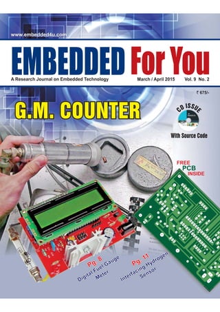
  • 1. With Source Code CD ISSU E ` 675/- March / April 2015 Vol. 9 No. 2A Research Journal on Embedded Technology EMBEDDEDForYou www.embedded4u.comwww.embedded4u.com G.M. COUNTERG.M. COUNTER Pg. 11 Interfacing Hydrogen Sensor Pg. 11 Interfacing Hydrogen Sensor Pg. 8 Digital Fuel Gauge Meter Pg. 8 Digital Fuel Gauge Meter FREE INSIDE PCB
  • 2. We invite you to participate in the incubation module which will offer a broader platform for you in reaching out to each and every section of the Embedded Industry. Sell your designs through Embedded ForYou. Get your designs manufactured through our tie-ups to contract manufacturers. Get recognized by getting your technical articles and research papers published through Embedded ForYou. We are capable of providing flexible and suitable product solutions from design to manufacturing, through our tie-ups with renowned business associates and leading manufacturing companies. l l l embedded4u@gmail.com www.embedded4u.com
  • 3. We are grateful to our readers for their tremendous response to Embedded For You that gave us a readership of over One million in such a short span of time. Automatika Electronic Bazaar E-pulse Networking Budding Scientist Techno Focus Envision Master Minds EMBEDDED FOR YOU 100 U.B., Jawahar Nagar, Delhi - 110 007 Ph.: 011 - 42381979 E-mail: embedded4u@gmail.com Website : www.embedded4u.com www.embedded4u.com Dedicated to the Embedded World
  • 4. 4 Embedded For You March / April 2015 March / April 2015, Issue 2 Embedded For You A journal on Embedded Technology CONTENTS Budding scientistS....................7 Departments E-Entertainment.............................................................................6 In News.........................................................................................13 Electronic Bazaar...................................................................15-18 Techno Trendz........................................................................33-34 Calendar......................................................................................36 Organizations Covered..............................................................37 Jobs For You................................................................................37 E4U Highlight 2007, 08, 09, 10, 11,12,13,14....................................................38-40 E4U Subscription form.................................................................41 Circuit ideas ISSN- 0973-791X EDITORMANAGING DIRECTOR TECHNICAL ADVISOR ADVISORY BOARD Harshita Gupta embedded4u@gmail.com Dr. Anshu Gupta embedded4u@gmail.com Divyansh Gupta divyu.gups@gmail.com DESIGN MANAGER Kiran Bala Ashok J.P. Gupta S. K. Gupta 100 U.B. Jawahar Nagar, Delhi - 110 007, Ph. : 09810543929 embedded4u@gmail.com ADVERTISEMENTS & QUERIES 100 U.B. Jawahar Nagar, Delhi - 110 007, Mob.: 9810014979 advertise@embedded4u.com, embedded4u@gmail.com SUBSCRIPTIONS AND MISSING ISSUES Envision - I......................................................................................8 ESAT Lesson - 51........................................................................11 Digital Fuel Gauge Meter Interfacing Hydrogen (H2) Sensor Brain Teaser..................................................................................9 Smart Circuit - I...........................................................................10 DIGITAL FUEL GAUGE METER
  • 5. Embedded For You Embedded For You March / April 2015 5 Master MindS...........................19 Techno focuS..........................28 Networking Automatica E-Pulse Bio-Buzz......................................................................................32 Circuit...........................................................................................29 Circuits.......................................................................................... Circuit...........................................................................................31 1 Ghz Millivoltmeter Latest news and product updates in medical field 30 Independent M:S Adjustment For Wide - Band Pulse Gen A Simple Charge Measuring Meter Embedded For You is published bimonthly on the last day of second month. Views and opinions expressed in this publication are not necessarily those of Academy of Embedded Technology. Academy of Embedded Technology reserves the right to use the information published in this issue whatsoever. While every effort has been made to ensure accuracy of the information published in this edition, neither AET nor any of its employees accept any responsibility for any errors. No part of this publication may be reproduced in any form without the written permission of the publisher. All right reserved. Printed and published by Sandeep Kumar Gupta. Printed at Goel Stationers, B-36/9, G.T. Karnal Road Industrial Area, Delhi - 110 033, and published from 100-U.B., Jawahar Nagar, Delhi - 7. Hardware Description of G.M. Counter.....................................25 Smart Circuits - II..........................................................................27 A Geiger counter (Geiger-Muller tube) is a device used for the detection and measurement of all types of radiation: alpha, beta and gamma radiation. ................................. G.M. Counter R1 15k Rem +15V Loc +15V Loc +15V Loc -15V Rem = Remote Power Loc = Local Power Tr1 Vcc GND R3 2k2 R7 2k R4 2k2 R5 11k R6 10k Tr2 Rem -15V Rem 0V Vin R2 15k D1 D2 IC1 6N136 IC2 AMP-02 Rg Rg Vcc Vout Loc 0V REFVee - + You can send subscription amount to current Ac.No. , Kotak Mahindra Bank, Kamla Nagar, Delhi 110007 . "EMBEDDED FOR YOU" 2611229474 IFSC : KKBK0000190, Please inform by sending a letter to our office for future records Envision - II.....................................................................................20 in continuation............ Please add Rs. /- for outside Delhi cheques Please prefer DD & send payments only in favour of 100 . EmbeddedFor You. Period In India Overseas One Year Two Year Three Year 125 US$ 250 US$ 350 US$ 3,950/- 7,500/- 11,250/- SUBSCRIPTION RATES Kindly add Rupees 300 for Postal charges.
  • 6. e-Entertainment 6 Embedded For You March / April 2015 harmonics, by adding a resistor of about 1M2 from the negative rail to the junction or R3 and R4. It also seems that the quote frequency of 800Hz was in error; the observed Figure 1 frequency was 2340Hz, approximately that at which the reactance of C1 (=C2) is equal to the COMMENTS ON “LOW DISTORTION OSCILLATOR” The oscillator described can be improved by making the second stage gain greater than one, and taking the output from the first stage rather than the second. In Figure 1. the values of R3 and R4 have been interchanged for this purpose the preset resistor Rf then needs to have approximately twice the original value but there are no other changes. The limiting now takes place in the second stage an the selectivity of the first stage is available to filter the resulting distortion. From an oscilloscope comparison the setting of Rf is considerably less critical than in the original circuit about 96% of the value required just to sustain oscillation is a reasonable compromise between waveshape compromise between waveshape and start - up time. A further improvement can be had by making the stage 2 clipping symmetri- cal, and so minimizing second Fast Full-Wave Rectification circuit idea is important tool for radio communication engineers and hobbyist in Loosely based on a design in which current mirrors sensed the supply current of op-amps, this circuit uses a MAX435 wide - band, differential output transconductance amplifier to give full -wave rectification of signals up to 250MHz. Output is 4Z / V for the MAX435 IC. One can also try the Burr-Brown OPA660, which offers 700MHz - pulse operation. L in geometric mean of R1 and R2, as might be expected. The oscillator may be implemented using only one op-amp, by applying positive feedback from the output terminal of the first op amp in the original diagram. To its non-inverting input, as in Figure 2. 220µF C1 10n C1 10n Out C2 10n C2 10n R1 1k R1 1k R6 1k Figure 1. Figure 2. R2 47k R2 47k R5 18k RV1 5K R4 47k R3 33k Amps TL072 Rf 33k approx. FAST FULL - WAVE RECTIFIER V1+ V1- Io+ Io- MAX435
  • 7. BUDDING SCIENTISTSBUDDING SCIENTISTS A Segment Contrived For Students Includes an Esat Lesson Plan, (Embedded System Application Training) Easy Projects and Circuits. Log on to : www.aet-embedtech.com Robotics Music & Audio Communication Digital Meter Research & Experiments Sensors Contents .........Page............................................................. Envision I........................................................................................8 Brain Teasers.................................................................................9 Digital Fuel Gauge Meter Interfacing Hydrogen Smart Circuit I..............................................................................10 ESAT Lesson................................................................................11 Logic Gates Sensor
  • 8. EnvisioN - I 8 Embedded For You March/ April 2015 amount of fuel that there is in a Bike. Bike owners need to be particularly aware of fuel level. Having a low amount of fuel can hamper the Bike performance and damage it in the long run. Good sensors are equipped with microprocessors, measure the fuel level in a high temperature environ- ment, and are designed for fast, on request delivery. Low power consum- ption and easy calibration are other distinguishing features. When properly functioning, fuel level sensors warn when refueling is required. The connection between the sensor and the Bike should be stable. A stable connection reduces the probability of getting false readings that may lead to the Bike stopping in the middle of the road if the vehicle has ran out of fuel. Although the sensor may indicate the right level of fuel, the indicator may go haywire as it can't interpret the data. Checking if the sensor is working is the best way to prevent accidents due to false information. Since Float inside the tank has some limitation of moment and shape of the tank is not linear. Wiring and Indicator Limitation Mostly Fuel gauges in your bike tells only mpty, id and ull position. it does not give a clear idea of fuel purchased. suppose your Bike fuel tank has fuel capacity of 15 liters. Now if you purchase only 10 liters, than there is no graduation on the indicator dial to indicate the 10 liter fuel purchase . Here we give you a idea to make digital fuel indicator for your bike using AET DPM kit and float type fuel sensor. Float type fuel level sensor are commonly use in bikes. It consist of float mounted on moving arm of potentiometer. These float sensor are mounted in the tank where float is inside the fuel and potentiometer is outside the fuel. The float in the fuel tank varies as per fuel level in the tank and controls the viper position from maximum to minimum. When the tank is full the float is at the top and the resistance of the potentiometer is maximum. When fuel tank is empty the float is at the bottom and resistance is minimum. suppose resistance of float sensor varies between zero to 100 ohms depending E M F upon the float sensor type and its maximum resistance. Since our battery voltage is 12 volts DC, if we connect the sensor to battery directly current flow will be 120 mAapprox, which is high, we can easily calculate using Ohms law ie V = I x R V = 12 DC Battery Voltage. R = Resistance of Float Sensor. I = Current in the Circuit 120mAapprox. We should further reduce this current otherwise battery will discharge early. So we connect 10,000 ohms resistance in series to Float Sensor, as per circuit given. A fuel level sensor informs about the DIGITAL FUEL GAUGE METERDIGITAL FUEL GAUGE METER Figure 1. Float Sensor connection diagram Open Float Sensor Digital Fuel Gauge AET DPM KIT 12VBattery 10k Wiper Sensor Signal GroundClosed
  • 9. EnvisioN - I Embedded For You March / April 2015 9 Brain Teasers 1. A few friends meet each morning for coffee. For one of them, it is the only cup of coffee all day. For another, it’s only the first of eight cups. Zowie ! Your challenge is to figure out how many cups of coffee each person drinks per day, how sugar lumps they use per cup, and whether or not they put in milk. a. Jan uses three times as many lumps as the person who drinks four cups. b. Three people, including the one who uses four lumps, use no milk. c. The one who drinks 1 cup day (not Max) drinks his coffee black without sugar. d. Doris uses both milk and sugar. e. Max, who uses no milk, uses half as many sugars as the person who drinks twice as many cups as he does. f. Boris drinks two more cups than Jan, but Jan uses two more sugars than Boris. Figure 1. Digital Fuel Gauge using AET DPM Kit Maxdrinks4cups,with2sugars,nomilk. Dorisdrinks5cups,with1sugar,milk. Blizzodrinks1cup,withnosugar,nomilk. Jandrinks6cups,with6sugars,milk. Borisdrinks8cups,with4sugars,nomilk. Max Doris Blizzo Jan Boris Cups Lumps of Sugar Milk 1 4 5 6 8 1 40 2 6 Yes No AET DPM KIT IC7107 PIN 31 PIN 30 1M 100n Float Sensor Open Battery 12V 10k Wiper Sensor Signal GroundClosed
  • 10. Smart circuitS-I 10 Embedded For You March/ April 2015 If you refer to the switching circuit for the transistor you will see that the output voltage is high (consider this as 1) when the input voltage is low (consider this as 0). This is the basic NOT gate - there is an output when there is not an input. Combinations of these switching circuits can be made into logic gates that will perform simple decisions within a microprocessor. These logic gates are the basis of all decisions within computers and from now on we will consider their effects rather then their internal structure. We will consider the following types of logic gate: (1) NOT gate - this gives an output 1 for an input of 0. (2) NOR gate - this gives an output 1 for neither of two inputs 1. (3) OR gate - this gives an output 1 for either of two inputs 1 and both The switching action of a transistor makes it especially suitable for use in digital logic circuits where the output is either 0 or 1 depending on the input. Applications of such circuits are to : a). Switch on a water pump on a hot sunny day. b). Sound an alarm if the pilot light of a boiler went off. c). Sound an alarm if a burglar stepped on a pressure pad or shone his torch. d). Switch a light on if it was a cloudy day. e). Add two simple binary numbers together. f). Switch on a fan if a darkroom door was shut and it was warm inside All these things and indeed many more can be done with ELECTRONIC LOGIC CIRCUITS. These circuits are ones that can make decisions. Different decisions need different circuits. LOGIC GATES inputs 1. (4) AND gate - this gives an output 1 for both two inputs 1. (5) NAND gate - this gives an output I for either but not both of two inputs 1 or both inputs 0. (6) EXCLUSIVE-OR - this gives an output I for either but not both of two inputs 1. (7) EXCLUSIVE-NOR - this gives an output 1 when both inputs are 0 or 1. Because of its wide use in modern digital electronics the NAND gate will be considered as a basic building block for a variety of logic circuits. In fact a number of other logic gates can be constructed from NAND gates as is shown below. The circuit in Figure 1 shows how a NAND gate might be constructed from discrete components, although it would normally be in the form of an integrated circuit. R1 R2 +6V F 0 A B NOT Input 1 0 1 Output F 1 0 AND Input 1 0 1 0 1 B 0 0 1 1 Output B 0 0 1 1 NAND Input A 0 1 0 1 B 0 0 1 1 Output F 1 1 1 0 OR Input A 0 1 0 1 B 0 0 1 1 Output F 0 1 1 1 NOR Input A 0 1 0 1 B 0 0 1 1 Output F 1 0 0 0 EXCLUSIVE OR Input A 0 0 1 1 B 0 1 0 1 Output F 0 1 1 0 EXCLUSIVE NOR Input A 0 0 1 1 B 0 1 0 1 Output F 1 0 0 1
  • 11. ESAT Lesson-51 Embedded For You March / April 2015 11 below a certain threshold value and are generally slow to respond. Like these sensors, the placement of H2 sensors, within a volume will be critical, as H2 is a very buoyant gas. For H2 alarm sensors, the detection range will likely be 0.5 to 4.0 percent H2 in air, with a response time of several seconds to tens of seconds. Once a large-scale leak is detected, the buoyant nature of hydrogen means that it is easily dissipated, making it ultimately a safer gas to use than heavy flammable gases which tend to settle. In contrast to leak detection, explosive- limit monitoring, H2 sensors are also required to monitor H2 going into a fuel cell. Technical challenges originate from the multitude of potential generation sources for the gas. These challenges include H2 from reformers, tanks, electrolysers, H2 storage media, biomass and other storage technologies. Catalytic Bead Sensors consist of two beads surrounding a wire operating at high temperature (450°C). One bead is passivated, so that it will not react when it comes into contact with gas molecules. The other is coated with a catalyst to promote a reaction with the gas. The beads are generally placed on separate legs of a Wheatstone bridge Interfacing Sensors Hydrogen (H2) Sensor Necessity of Hydrogen Sensor. Explain the working of . Study of Applications of . Interfacing Microcontroller to . Hydrogen Sensor Hydrogen Sensor Hydrogen Sensor After completing this section you should be able to : circuit. When hydrogen is present, there is no measurable effect on the passivated bead, whereas there is a significant effect on the catalyzed bead. The increase in heat increases the resistance in that leg of the Wheatstone bridge circuit, which in turn changes the bridge balance signal, which is the sensor signal. In terms of performance specifications, catalytic bead technology is generally used in the 1 to 5 percent H2 range. The response times of the sensor varies, ranging from 10 to 30 seconds for full-scale response Semiconductor Sensors. Solid state sensors utilizing semiconducting oxides generally operate at temperatures above ambient. The electrical resistance of the sensor material will also depend on temperature, and also on the chemical composition of the surrounding atmosphere. These sensors do offer fast response in the range of 0- 1000ppm H2, therefore are useful in leak-detection applications on the end of a sensor wand. Hydrogen Field Effect Transistors (HFET). By using palladium as the gate material for a standard field effect transistor, small changes in the resistivity of the palladium produce large changes in the current-voltage characteristics of the FET. This sensor technology works well in Introduction Hydrogen is emerging as a primary fuel source to replace oil-based fuels. Hydrogen-based fuel cells will be the mechanism by which electrical energy will be derived from the reaction of hydrogen and oxygen gases within the fuel cell to make water. All fuel cells require two types of sensors; the first monitors the quality of the hydrogen feed gas, and the second for leak detection. Hydrogen leak-detection sensors must detect over the general level of ambient hydrogen levels, and in a variety of environments. Leak detection can be accomplished by two types of sensors: one to detect the leak and a second alarm sensor with a set-point set at 50 percent of the Lower Explosive Limit (LEL) of 4 percent hydrogen in air. The need for leak detection is especially acute where there is a large volume of hydrogen consumed. For example, in residential/stationary applications and in automotive applications, where the fuel cell sits in an enclosed volume. The demands on the explosive-limit sensors and the leak-detection sensors are naturally different. Explosive-limit sensors have similar metrics to current domestic CO or fire alarm sensors, in that they are continuously on, do not need to sense
  • 12. ESAT Lesson-51 12 Embedded For You March/ April 2015 elements at a nominally constant temperature, thereby decoupling thermal resistivity changes from those changes occurring as hydrogen is diffused into or out of the palladium alloy lattice. mapping of the H2 field can be done over long distances. Sensitive material of MQ-8 Hydrogen gas sensor is SnO2, which with lower conductivity in clean air. When hydrogen gas exists, the sensor's conductivity gets higher along with the the range of 50 to 1000ppm range of H2. As a palladium-based sensor technology, it functions independently of the environment. Sensors for Fuel Cells, Which comprises a triple redundant palladium alloy thin-film resistor and an HFET, which offers six orders of magnitude in hydrogen detection on a single chip. In addition to the sensing elements, the sensor also has embedded heater circuits which keep the sensor * adjust the value for best output ( ) PC6RESET VCC GND 1 7 8 (XTAL1) PB6 ATMega8L (ADC5/SCL)PC5 (ADC4/SDA)PC4 (ADC3)PC3 (ADC2)PC2 (ADC1)PC1 (ADC0)PC0 28 27 26 25 24 +5V Vc - 23 9 10 (XTAL2) PB7 XTL 8MHz C7 100mF Figure 3. Basic Measurement of Hydrogen (H ) Level2 +5V R Set * TH 1k GAS H2 Sensor 2 5 6, 4 1, 3 +Ve -Ve V Heater Keypad connection C9 10 Fm R2 8K2 +5V C4 33pF C5 33pF C8 0.1 Fm R L RS RH (MOSI/OC2) PB3 (MISO) PB4 16 17 18 15 (SCK) PB5 (OC1A) PB1 19 (SS/OC1B) PB2(RXD) PD0 (TXD) PD1 (INT0) PD2 (XCK/T0) PD4 (AIN0) PD6 (AIN1) PD7 (ICP1) PB0 2 3 4 6 12 13 14 +5V 16 +5V 1 Figure1. Typical Sensitivity Curve Figure 2. Typical temperature / humidity characteristics 1 Rs/Ro Rs/Rso (ppm) 100 1000 10000 1.9 1.7 1.5 1.2 1.1 0.9 0.1 0.5 -20 0 20 40 50-10 10 30 0.1 0.01 60%RH 30%RH 85%RH H2 Air Alcohol CO CH4 The ordinate is resistance ratio of the sensor (Rs/R0), the abscissa is concentration of gases. Rs means resistance in target gas with different concentration, R0means resistance of sensor in clean air. All tests are finished under standard test conditions. The ordinate is resistance ratio of the sensor (Rs/Rso). Rsmeans resistance of sensor in 1000ppm H2gas under different tem. and humidity. Rso means resistance of the sensor in 1000ppm H2gas under 20 /55%RH.℃ gas concentration rising. Users can convert the change of conductivity to correspond output signal of gas concentration through a simple circuit. Hydrogen gas sensor has high sensitivity to hydrogen gas, also has anti-interference to other gases. The Figure 3 is the basic test circuit of Hydrogen Sensor. While VRL is the voltage of load resistance RL which is in series with sensor. Vc supplies the detect voltage to load resistance RL and it should adopts DC power. Interfacing with Microcontroller When H2 percentage is high sensor resistance changes, since constant current is passed though the resistive element, change resistance is converted into change in voltage and it is measured by by AD off micro- controller and also temperature is monitored using thermistor. See the output characteristic of sensor and its temperature dependency to calculate the H2 concentration.
  • 13. Embedded For You March / April 2015 13 In newS Arrow has extended its IoT portfolio with a TI SimpleLink wireless MCU platform and is stocking development kits to help customers get into IoT. The SimpleLink supports communications protocols including Bluetooth low energy, ZigBee, 6LoWPAN, Sub-1 GHz and ZigBee RF4CE. There are ready-to-use protocol stacks. SimpleLink has an ARM Cortex–M3 core, Flash memory,ADC, peripherals, sensor controller and built-in on-chip security. AMD announced that the AMD Embedded R-Series accele- rated processing unit (APU), previously codenamed “Bald Eagle,” is powering the latest set-back-box (SBB) digital media players from Samsung Electronics, Co., Ltd. With high performance, low power, and broad connectivity, the new Samsung SBB-B64DV4 is an ideal fit for demanding signage applications that transform Samsung SMART Signage Displays into inclusive digital tools for a wide range of business needs. Stanford University has produced an aluminium ion cell with “no decay over hundreds of cycles, even thousands of cycles”, according to scientist Ming Gong, yet it can be charged in a minute. Key to long life, according to a paper in Nature (‘An ultrafast recharge- able aluminium - ion battery‘), is using a three-dimensional graphitic-foam for the cathode. In a study, it identified a few types of graphite material that give us very good performance.” Arrow kits for IoTAluminium ion battery hits thousands of cycles for grid storage AMD Embedded R-Series APU Powers Samsung Electronics’ Digital Signage Systems Microsemi has introduced a range of radiation-tolerant FPGAs intended for space applications requiring up to 150,000 logic elements and up to 300MHz of system performance. Typical uses for RTG4 include remote sensing space payloads, such as radar, imaging and spectrometry in civilian, scientific and commercial applications. Other applications include mobile satellite services (MSS) communication satellites, as well as high altitude aviation, medical electronics and civilian nuclear power plant control. FPGAs for big space satellites Fujitsu Laboratories Ltd. announced the development of Web OS technology that automatically connects smartphones, regardless of operating system, to peripheral devices and sensors, and enables integrated use with cloud services. Conventionally, connecting peripheral devices to smartphones, tablets, and other smart devices requires a dedicated application on the smart device for each device, with different versions for different OS. M/A-COM Technology has developed a 650W gallium nitride (GaN) on silicon carbide (SiC) HEMT pulsed power transistor for L-band pulsed avionics applications. The transistor is available in standard flange or earless flange packaging. Designated the MAGX- 000912-650L00/MAGX-000912- 650L0S, it is a gold metalised, internally matched, GaN-on-SiC depletion mode RF power transistor. Operating in the 960 to 1215MHz frequency range, the MAGX- 000912-650L0x is a rugged and robust transistor, boasting a mean time to failure (MTTF) of 600 years. Fujitsu Develops Web OS Technology GaN technology gives 650W power transistor Seeking funding through Indiegogo, Codie is a robot toy that teaches the principles of coding to children. Via a phone app, the robot is moved by simple drag-and-drop graphical instructions that include: variable, loops, branches and sub-routines. Sensors on- board measure distance, acceleration and direction. “Kids control the Codie robot with a touch-screen app featuring a visual coding language that organises robotics code into action blocks. Cypress Semiconductor is sampling a USB Type-C cable controller which includes power delivery (PD) on a small footprint. It is designed for use in 2.4mm thin USB Type-C cable connectors. The programmable EZ-PD CCG2 controller is capable of supporting any USB Type- C downstream facing port (DFP) or upstream facing port (UFP) applications. It is available in a 3.3 mm2 wafer level chip scale package (WLCSP) and is notable for integrating both the Type-C transceiver and termination resistors needed for Type-C communication. Microcontroller fits in a USB Type-C connectorKids robot teaches coding TM
  • 14. Siemens researchers have developed a new type of electric motor that, with a weight of just 50 kilograms, delivers a continuous output of about 260 kilowatts – five times more than comparable drive systems. The motor has been specially designed for use in aircraft. Thanks to its record-setting power-to-weight ratio, larger aircraft with takeoff weights of up to two tons will now be able to use electric drives for the first time. Toshiba has announced a new ARM Cortex-M4F based microcontroller for use in secure systems control. Called TMPM46BF10FG and part of the firm’s TX04 range, it incorporates a true random number generator (TRNG: SP800-90C standard) through a random entropy seed generation (ESG) circuit and Hash-DRGB created by the secure hash processor (SHA) and software program. It is intended for IoT devices, energy management systems, sensors and industrial equipment. Tektronix has introduced the entry level AFG1022 arbitrary / function generator which is affordable for educational institutions and companies on a budget. Its specifications are more impressive t h a n s c o p e - b a s e d s i g n a l generators. The dual-channel generator has 25MHz bandwidth with 1mVpp to 10Vpp output, 14-bit vertical resolution and 1µHz frequency resolution. It provides a 125Msample/s sample rate along with 64Mbyte of built-in non-volatile memory and USB memory expansion for user-defined waveforms. Nanotec of Germany has introduced a 42mm flange motor with integrated controller and encoder. Called PD2-C, it comes in two electro-magnetic options: 12-48V stepper motor with 0.5Nm nominal torque, or brushless dc (BLDC) motor with 105W nominal output, peaking at 315W. Due to its field-oriented control, the stepper motor behaves like a high-pole DC servo – with a higher torque but lower nominal speed than a BLDC motor. Therefore many applications can be realised without a gear. Printed electronics firm Thin Film Electronics has developed a near field communication (NFC) sensor for tagging bottles which can detect when a product is “sealed” and “open”. Likely to be used for tagging wine and spirits, pharmaceuticals, cosmetics and automotive fluids, the tag is designed to provide NFC-readability before and after a factory seal on the product has been broken. According to the Norway-based company, it is possible to provide content to mobile devices on “sealed” or “opened” status, as the consumer’s context shifts from “pre-purchase” to “in use.” PCB DFM check service on artwork from any EDA tool set NFC tag will provide product marketing information Tektronix targets low cost sig gen at schools NI’S New CompactDAQ Controllers Small motor with integrated controller Toshiba adds encryption to Cortex-M4F for IoT In newS 14 Embedded For You March / April 2015 NI (Nasdaq: NATI), the provider of platform-based systems that enable engineers and scientists to solve the world’s greatest engineering challenges, announced the new Compact DAQ 8-slot controller, which expands the CompactDAQ controller offering to meet high-channel count applications in rugged environments. By integrating the processor, signal conditioning and I/O into a single CompactDAQ system, engineers can reduce overall system cost and complexity while increasing measurement accuracy. Anritsu has introduced the ShockLine MS46121A series of 1-port USB vector network analysers (VNAs). Two models with frequency coverage of 40MHz to 4GHz and 150kHz to 6GHz are powered and controlled by a PC through the USB port. Sweeps can be conducted at 100 microseconds per point and the MS46121A VNAs have a corrected directivity of 42dB so engineers have greater measurement confidence. The MS46121A series is controlled through software that provides the tools and graphical user interface (UI) for debug and testing of 1-port RF devices. It also provides remote programming capabilities. USB-based 6GHz vector network analyser World-record electric motor for aircraft Winchester-based PCB design house Professional Circuit Designs (PCD) is offering design for manufacture (DFM) checks for Gerber and ODB++ files. PCD can also modify the Gerber or ODB++ files to pass DFM checks against ERFs (electronic rules files) from several PCB makers, giving the customer a choice of more than one production site from a common data set.
  • 15. MASTER MINDSMASTER MINDS A Segment For Engineers Professional and Hobbyist, Featuring Circuits and Embedded Projects. Contents...........................................................Page Envision II.........................................................................20 25 Smart Circuits II................................................................27 G.M. Counter Hardware Description. Fuse Replacement by Variable Semiconductor ....................................................... Log on to : www.aet-embedtech.com Communication Medical Electronics Home AutomationMusic & AudioRobotics Research & Experiments
  • 16. EnvisioN-II 20 Embedded For You March /April 2015 Introduction History - GM Detector Physics principle behind GM Detector tube Theory of Operation AGeiger counter (Geiger-Muller tube) is a device used for the detection and measurement of all types of radiation: alpha, beta and gamma radiation. Thanks to an ingenious German physicist named Hans Geiger, we've all heard the sound of radioactivity. It's just as well we do have Geiger counters because most radiation (radioactive particles and energy) is extremely harmful to living things, completely invisible, and very difficult to detect in other ways. A "Geiger counter" usually contains a metal tube with a thin metal wire (Figure 1.) along its middle; the space in between them sealed off and filled with a suitable gas, and with the wire at a very high positive electric potential relative to the tube(a). An electron, positive ion, or gamma radiation penetrating the tube through a mica window, will ionize a number of the atoms in the gas(b), and because of the high positive voltage of the central wire, the electrons will be attracted to it while the positive ions will be attracted to the wall(c). The high voltage will accelerate the positive and negative charges, they gain more energy and collide with more atoms to release more electrons and positive ions; the process escalates into an "avalanche" which produces an easily detectable pulse of current. With a suitable filling gas, the current quickly drops to zero so that a single voltage spike occurs across the resistor R and that is registered by an electronic counter. A scaler counts the current pulses, and one obtains a”count” whenever radiation ionizes the gas (Figure 2.). As explained in the working principle of GM counter, the collection of the charge thus produced results in the formation of a pulse of voltage at the output of the tube. The amplitude of this pulse, on the order of a volt or so, is sufficient to operate the scaler circuit with little or no further amplification. G.M. COUNTERG.M. COUNTER
  • 17. EnvisioN-II Embedded For You March / April 2015 21 1. Plateau curve 2. Dead-time of the GM counter Every GM tube has a characteristic response of counting rate versus voltage applied to the tube. A curve representing the variation of counting rate with voltage is called a plateau curve (Figure 3). The counter starts counting at a point corresponding approximately to the Geiger threshold voltage; from there follows a “plateau" with little change in the counting rate as the voltage increases. Finally a point is reached where the self-suppressing mechanism no longer works, and the counting rate rapidly increases until the counter breaks down into a continuous discharge. In order to ensure stable operation, the counter is operated at a voltage corresponding approximately to the mid-point of the plateau. Plug the Geiger-Müller tube into the scaler (counter) and switch on. Start the voltage at about 200 volts. Make a note of the number of counts in, say, a 15 second interval. Increase the voltage in steps of 25 volts. You will find that the counts vary with voltage and then reach a plateau. A graph would look like this (you do not need to plot the graph): After the threshold voltage, the count will reach a plateau. It will stay constant over a range of voltages. Set the voltage at a value of between 50 to 100 V above the threshold. If the clicking increases when you increase the voltage, then you have moved off the plateau. Turn the voltage back down. Put the source back in a safe place until you carry out the demonstration. As determining the plateau is an important aspect, so is determining the dead time. Build-up of the positive ion space charges after each discharge process turns the G-M tube off for the next incident radiation measurement. A considerable amount of time should elapse before next avalanche can take place in the tube. Depending on the physical characteristics of the Determining the Plateau : l l l l l l l l l Figure 1. The Geiger Counter R Voltage Spike to Counter Central Wire (+ Voltage) Outer Cylinder (- Voltage)Mica Window a b g, , or radiation V + (a) (d) (e) (e) (b) ---------------------- + + + ++ + + ++++ + + + + ++ + + + + + + + + + + + + + + + + + + + + + + + + + + + + + + - - - - - - - --- - -- - - - - -+ + + + + ++ + + ++ + + + + + ++ + ++ + + - + Gm Digital Voltmeter GM Tube Source Oscilloscope Scaler Timer High Voltage Supply Figure 2. GM Counter block diagram Figure 3. Geiger Tube Voltage Characteristics Counting Rate Proportional Discharge Region Geiger Plateau Continuous Discharge Region Applied Voltage Start Voltage Geiger Threshold Voltage Operating Voltage V0 Geiger Breakdown Voltage
  • 18. EnvisioN-II 22 Embedded For You March / April 2015 detector, this time is of the order of 20 to 300 s. This dead period makes the G-M tube response as a nonlinear and complicated function of the incident radiation intensity. As it is visible from Figure 4. there is a time needed to process the interaction and during that time, no further pulses will be registered; this is known as the dead time or paralysis time. Dead times range from a few µs for scintillation and the smallest GM types to a few hundred µs for larger GM types. The effect of dead time is shown in the figure below. where = dead time of detector following an interaction A total of 6 events occur within the detector (a) but only 4 counts are registered (b). Events 3 and 5 will not be registered because they occur during the dead time period of the detector. Seeing the Operation Principle of GM Tubes, now we have a fare idea of what features are required from a microcontroller so that a prototype of a GM Counter can be made. 1) Minimizing DeadTime losses 2) Timer - Start and Stop Pulse counts 3) Boost Converter - 400V Power Source 4) Final Output – Counts Per Minute (uSV /Hours to CPM ) Dose Equivalent is measured in sievert (Sv) (Rem in the U.S.) Based on Atmega-328p and programmed with Arduino IDE. In compare to other Arduino based Geiger counters on the market, this product has reduced components amount that makes this project very easy to solder. The kit has basic simple function to count GM tube events (CPM) and calculate gamma radiation DER for ambient background level or for low-moderate radioactive samples. Since it's educational Arduino IDE project, do not rely on its readings in real hazardous situations ! The software and hardware where designed to produce tube high voltage with PWM technology. No additional IC's required, everything is controlled with software. By default it programmed to 400V-420V and you can make fine adjust through software calibration from 350V to 480V. If required, the kit can be adjusted for 500V-550V. For higher voltage it possible to make 600V hardware mode. Complete design Schematic and Software code to make your GM counter is provided in the Software CD. Following is Explanation of GM counter construction a. Generation of high voltage and biasing the GM tube. b. Acquisition of raw analogue pulses from GM-tube. c. Conditioning the raw pulses to form logic pulses. d. Counting the logic pulses with time gating. e. Display the counts per second or the dose information. Generates a variable duty PWM signal using Timer1, to drive the 400V inverter needed to operate the Geiger tube; The invertor doesn't need a multiplier, as the ferrite's transformer μ τ Effects of dead time on detector GM Detector Board Features of Microcontroller Theory Generation of High Voltage Figure 4. Schematic of pulse train at high counting rates. The discrimination level is set to 2V. Due to dead time effects, some pulses do not cross the discrimination level, i.e. they are not recorded as valid events. 5.5 5 4.5 4 3.5 3 2.5 2 1.5 1 0.5 0 PulseAmplitudeV Time sm Pulse Train and Their Losses Fast portion of the G-M detector pulse after amplification block with a rise time less than 1ms 2 V Discrimination Level Due to dead time effects, these pulses are not recorded as valid events 1000 200 300 400 500 600 700 800 900 1000 1 62 Event in detector Event registered t 43 a) b) 5 1Event Number Counted ? a 2 a 3 X 4 a 5 X 6 a
  • 19. EnvisioN-II Embedded For You March / April 2015 23 secondary puts out exactly the amount required. The transformer is made on aA22 ferrite core, with 16 turns in the primary and 600 in the secondary. Figure 5 shows a simple boost converter which works on the principle of fast switching of an inductor current between two different levels. In the schematic shown, the switch is initially closed for a long time and a constant current is established in the inductor. Now, when the current is suddenly switched from the established constant value to zero by opening the switch a high voltage is generated on the pole side of the switch. This momentarily generates high voltage that can be stored in a capacitor through a diode and further processed to act as a source. Since any load connected to the capacitor discharges it, the capacitor charge should be constantly replenished by repetition of the switching action. This is done by replacing the mechanical switch with a switching transistor with a pulse signal in its base terminal. There is a simple relation between the input voltage (Vin) and the output voltage (Vout) of a boost converter in terms of the duty cycle (D) which states. The high voltage generated depends on the duty cycle of this pulse signal.The duty cycle ), thereby enabling a current through the inductor to the total cycle time, (There is the ratio of the time for which the switch is kept closed (Ton + Toff), i.e., switch closed time added with that time for which switch is open) Thus, as the duty cycle approaches unity, output voltage (Vout) that is greater than the input (Vin) can be generated. This relation establishes that a constant high voltage source can be realized using duty cycle control of the switching transistor. a. High voltage isolation b. Overshoots due to sudden switching (inductive effect of the central conductor). These issues can be solved by the implementation of a conditioning circuit as shown in Figure 3. Then there is a voltage divider connected to the case of the GM tube. This voltage divider is composed of 10K and 100K resistors with a 220 pf bypass capacitor. Then there is a voltage divider connected to the case of the GM tube. This voltage divider is composed of 10K and 100K resistors with a 220 pf bypass capacitor. The output of this voltage divider, which lowers the high voltage pulse from the GM tube, is feed to an NPN transistor which converts the analogue signal from GM-tube to form a logic pulses. As the conditioning of the logic pulses as now been done, it's time to count the logic pulses. d. Counting the logic pulses with time gating. e. Display the counts per second or the dose information. https://sites.google.com/site/diygeigercounter/gm-tubes- supported Duty Cycle Precaution Acquisition of raw analogue pulses from GM-tube Conditioning the raw pulses to form logic pulses Plan your Code References R1 4.7 Mohms High Voltage Analog Processing * Buffer * Comparator Regulated Clamp Voltage Regulated diode drop compensation Clamping network with overshoot clipping, DC blocking etc.. Figure 5. Complete Clamping Circuit with overshoot protection and high voltage isolation
  • 20. EnvisioN-II 24 Embedded For You March / April 2015 http://www.npl.co.uk/ https://www.cpp.edu/ http://physics.niser.ac.in/labmanuals/sem6/GM.pdf https://www.cpp.edu/ // configure atmega IO pinMode(LIGHT, OUTPUT); // turn on backlight digitalWrite(LIGHT, HIGH); pinMode(LED, OUTPUT); // configure led pin as output digitalWrite(LED, LOW); pinMode(2, INPUT); // set pin INT0 input for capturing GM Tube events digitalWrite(2, HIGH); // turn on pullup resistors pinMode(BUTTON_UP, INPUT); // set buttons pins as input with internal pullup digitalWrite(BUTTON_UP, HIGH); pinMode(BUTTON_DO, INPUT); digitalWrite(BUTTON_DO, HIGH); pinMode(A5, OUTPUT); // Set A5 as GND point for buzzer digitalWrite(A5, LOW);-starting tube high voltage------------ ----------// //----------------- load parameters--------------------// #define RAD_LOGGER true // enable serial CPM logging to computer for "Radiation Logger” #define SMART_BL true // if true LCD backlight controlled through ALARM level and key, else backlight is always on #define ACTIVE_BUZZER true // true if active 5V piezo buzzer used. set false if passive soldered. #define EEPROM_LOG true // if true will log absorbed dose to eeprom every 60 minutes. Use only if there is no Logging Shield available! // install supplied libraries from lib.zip! #include <Arduino.h> #include <avr/pgmspace.h> #include <EEPROM.h> #include <LiquidCrystal.h> #include <SPI.h> #include "Configurator.h” //-------------------------------------------------------// //-----------------Define global project variables----------------// unsigned long CurrentBat; // voltage of the battery unsigned long counts; // counts counter unsigned int countsHSecond; // half second counter static unsigned long value[] = {0,0,0,0,0,0}; // array variable for cpm moving algorithm static unsigned long cpm; // cpm variable static unsigned long rapidCpm; // rapidly changed cpm static unsigned long minuteCpm; // minute cpm value for absorbed radiation counter static unsigned long previousValue; // previous cpm value unsigned long previousMillis = 0; // millis counters unsigned long previousMillis_bg = 0; unsigned long previousMillis_pereferal = 0; unsigned long previousMillis_hour = 0; int n = 0; // counter for moving average array long result; // voltage reading result int buttonStateDo = 1; // buttons status int buttonStateUp = 1; unsigned int barCount; // bargraph variable static float absorbedDose; // absorbed dose static float dose; // radiation dose static float minuteDose; // minute absorbed dose boolean savedEeprom = false; // eeprom flag boolean event = false; // GM tube event received, lets make flag //boolean limit = false; // absorbed dose limit flag int cps_bar = BARGRAPH / 60; // fast bargraph scale for cps //-------------Roentgen/ Sieverts conversion factor-------------- --// float factor_Rn = (FACTOR_USV * 100000) / 877; // convert to roengten float factor_Sv = FACTOR_USV; float factor_Now = factor_Sv; // sieverts by defautl int units; // 0 - sieverts; 1 - roentgen //-----------------------------------------------------------------// //-------------------Initilize LCD---------------------// LiquidCrystal lcd(9, 4, 8, 7, 6, 5); //----------------------------------------------------// /////////////////////////////////////////////////////////////////////////////////////////// //------------------------------------------------------------------SETUP AREA--------------------------------------------------------------------// /////////////////////////////////////////////////////////////////////////////////////////// void setup() { // zero some important variables first counts = 0; countsHSecond = 0; minuteCpm = 0; minuteDose = 0; n = 0; cpm = 0;
  • 21. EnvisioN-II Embedded For You 25March / April 2015 Assembled Kit of G.M. Counter Kit can be purchased Online, Please contact: embedded4u@gmail.com Hardware Description of G.M. Counter +5V T1 KSP44 T2 2N3904 C8 100µ C11 300pF C10 10nF 1000V C9 100µL2 10mH L1 P2 1K R5 1K R3 4.7M R8 100R D1 4937 D2 4937 R8 10K + Geiger Tube R9 100K +5V C1 100n GND TX RST VCC RX ()RESETPC6 VCC GND 7 8 PB6(XTAL1) ATMega8L (ADC3)PC3 (INT0)PD2 (OC1B)PB2 (ADC2)PC2 (ADC1)PC1 (ADC0)PC0 9 10 PB7(XTAL2) X1 16MHz C7 100mF C4 10Fm +5V C5 22pF C6 22pF 2 1 23 3 24 26 16 PB1(OC1A) (RXD)PD0 (TXD)PD1 PD4(XCK/T0) PB0(ICP1) PD6(AIN0) PD5(T1) PD7(AIN1) 15 6 14 13 12 11 16 +5V 1 25 4 R11150E R13150E R4150E R10 10K R1 8K2 R12 10K R7 1K B_UPB_DN +5V+5V+5V +5V T3 BC547 C2 1000Fm REG1 7805 INOUT GND C3 100Fm D8-12V.C. +5V PowerSupplySection R2 4K7 D3 1N4007 ON
  • 22.
  • 23. Smart circuitS-II Embedded For You March 27/ April 2015 FUSE REPLACEMENT BY VARIABLE SEMICONDUCTOR output at A. Monoshot 74121 has been used to restrict any further pulses coming from the previous op-amp during ‘ON’ and ‘OFF’ time. An Ic7490 counter in 2 configuration has been used to trigger the triac. Voltage drop across 0.1 (high wattage) resistance (which can be reduced or replaced by a current meter) is fed to an amplifier in the feed-back loop. The amplified voltage is passed through a diode and a parallel combination of 5 F and 10pF capacitors which help in reducing the transient (a high voltage drop across 0.1 due to heavy current at the time of switching ‘ON’). The DC voltage developed across the capacitors is fed to the op-amp. As soon as the voltage at pt B exceeds V , the output state of the op-amp changes and trips ‘OFF’the circuit. This circuit also senses the ¸ W m W R The circuit has been designed to replace the fuses of high as well as low current rating by a semi-conductor trip system utilizing the triac of high as well as low power rating. The current rating of this S.C. fuse can be adjusted by choosing a right value of the reference voltage V of the feed-back loop and hence a particular value of the fuse in amperage can be set by a particular value of reference voltage V . Thus the same circuit can act as a fuse different current rating. Initially, the high input impedance of op-amp 741 which has been exploited is in the order of 1M as a tough switch. The impedance of the human body being in the order of 500k and hence when the op-amp 741 is used in the comparator configuration, a simple, touch of the finger at ‘S’ will change the state of the R R » W » W voltage changes in the mains supply efficiently. When the mains ac voltage exceeds 220V rms, the given circuit trips ‘OFF’the supply to load and hence puts the triac to ‘OFF’stage. The importance of the circuit lies in the fact that it replaces the fuse which is a consumable item. where as in this circuit nothing is consumable and therefore has a long life expectancy. Moreover, the trip time is very small as compared to the fusing time of the fuses made until now. The trip time decreases with the increases with the increase of load current from the designed fuse (in this case a S.C. fuse) current. This would avoid damage of costly and sensitive equipments either due to voltage fluctuations or any short circuit inside the equipment occurring suddenly. Vcc+5V S 1.8k 2 3 3 2 3 2 B 7 7 7 4 4 6 6 4 6 A 1000µF 25V 2.5µf 10V 10µF 25V 5µF 25V 1µF 10µf 25V 10µf 25V 10µF 25V 0.22µF 10V 0.47µF 2.5µF 1.8k 1.8k 10k 100k 100W LED 100W 0.1 or (current meter) W 1.8k 3V 330k 5.6k 10pF 47k VR 1k 56k LOAD 220V / 50Hz (r.m.s.) ST 044 4 14 3 5 14 12 5 7 2 6 7 10 11 74121 741 741 7490 10
  • 24. TECHNO FOCUSTECHNO FOCUS A Segment Pertains to the Arena of Automation, Communication and Medical Sector Contents Page..................................................................... Networking Circuits ................................................................................29 Automatika Circuits ................................................................................30 E-Pulse Circuits ................................................................................31 Bio-Buzz...............................................................................32 1 Ghz Millivotmeter Independent M:S Adjustment For Wide - Band Pulse Gen A Simple Charge Measuring Meter Latest news and product updates in medical field Log on to : www.aet-embedtech.com
  • 25. NetworkinG Embedded For You March / April 2015 29 1 GHZ MILLIVOLTMETER Figure. 5. Complete circuit diagram. C1 22n C2 1n C4 220n C5 2n2 C9 22n R14 10k R12 2k2 1N4148 R11 15k C11 10µ C10 47µ M1 0-2V R39 2k2 R4 1k R7 15k R8 330kR9 10k R10 10k R37 2k2 R36 2k2 R45 2k2 R30 6k8 R33 1k5 C23 2n2 R29 10k R32 1k8 R31 10k R34 2k2 R46 2k2 R35 2k2 C22 2n2 R41 2k2 R6 2k2 R5 2k2 R15 10k R13 330k R40 2k2 +Vs +Vs +Vs -Vs -Vs -Vs S1aC6 100p Tr1 BC173C C3 22n C3 22n C8 22n 5 6 4 D3 D4 R1* -20 R2 390k R3 1k R38 10k R47 1k8 L1 L2 2 6 D1 D2 -- ++ - - + + - - - + + + 2 3 A 3 2 3 2 3 2 1 2 6 5 11 12 10 6 1 6 7 B +Vs -Vs1 IC1 IC2 IC3a IC3b IC7LF356 LM311 IC8 IC9a IC9b IC9c LM308A CA3193 LM358 C12 2µ2 C13 10µ C14 18p C21 2µ2 T1 C17 560p C15 6n8 C18 6n8 C16 5n6 C19 5n6 C20 560p R16 10k R19 10k R24 10k R20 10k R25 10k R21 10k R26 10k R22 10k R27 10k R23 10k R28 10k R18 2k7 R17 8k2 R42 560 R43 560 R44 560 S1b S1c B A - - - + + + 3 2 2 3 3 2 6 6 1 IC4 IC5 IC6 LM318 LF356 LF356 7 IC1 IC2 IC3 Decoupling 100n IC4 IC5 IC6 IC7 IC8 IC9 4 44 4 4 74 44 7 8 7 7 7 7 8 14 +8V -8V The circuit diagram of the meter is depicted in Fig.5. Error voltages is first log. amplified (Ic1 in the probe), then rectified (Ic2) and low pass filtered (R4, C10). the following stage (Ic3a, 3b) is a balanced to ground, low output impedance d.c. amplifier. Potentiometers R40, R41 null offsets (zero meter indication with zero rectifier input), balance is adjusted by means of R39 although metering is balance error free. The output of the succeeding chopper, a b khz square wave, is them amplified in meter calibration amplifier Ic4. This stage functions also as an impedance buffer between chopper and the first active filter. Separate calibration potentio- meter, R42, R43, R44, are provided for each subrange to compensate for minor discrepancies in transformer T1 ratios. Two cascaded low pass Butterworth active filters (Ic5, Ic6) that follow, concert the square wave into a sinusoidal voltage which, suitably divided by switchable ratio transformer T1(1:1, 10:1, 100:1), is finally delivered to the comparison detector in the probe. Auxiliary circuits to switch to chopper comprise, 5KHz frequency oscillator Ic7, shaper driver Ic8 and inverter driver Ic9, R45 and R46. To be continue.........
  • 26. AutomatikA 30 Embedded For You March / April 2015 Independent m:s Adjustment for Wide - Band Pulse Gen This circuit delivers square waves and rectangular waves with a mark : space ratio of 10 - 90 % at frequencies from 1.2kHz to 2.7MHz. Frequency generation comes from the voltage controlled oscillator Ic1 and coming by way of the selector switch from outputs Q1 - Q9, output frequencies being 1/10 of the input from Ic1, as in the square waveform from carry output C0. associated components., the output of which is adjustable from 12KHz to 27MHz by means of the potentiometer. Johnson counter Ic2 provides a Set pulse from the Q0 output to the SR flip- flop Ic3, the corresponding Reset pulse 1k5 15 -5V 6 7 14 13 15 2 3 1 5 6 Output Frequency 1.2KHz - 2.7KHz 4 3 2 4 7 10 1 5 6 9 11 12 0 1 2 3 4 5 6 7 8 9 CO 1 2 3 4 5 6 7 8 9 0 CLK CLKEN RST VCO IN12P IC3 HCT4046 IC2 HCT4017 VC OUT R1 9 4 3k3 3k3 A B C D E Example shows waveforms for switch in position 3 Three Ics form a 1.2KHz - 2.7MHz pulse and square - wave generator having a mark - to - space ratio adjustable in 10% steps from 10% to 90% ‘A’ ‘B’ ‘C’ ‘D’ ‘E’ 3 5 8 14 100k
  • 27. e-pulse Embedded For You March / April 2015 31 Simple Charge Measuring Meter Experiments involving the manu- facturing of optical waveguides by electron beam irradiation on a glass substrates, requires the accurate measurement of electrical charge to control the refractive index variation of the substrate. In the particular experiment of incremental charge and accumulated charge were required in increments of 0.001 Coulomb up to a total charge of 100,000 Coulombs. A further requirement was to isolate requirement was to isolate the meter circuit from the measuring system. A simple system for implementing the Each time that an increment of charge of 0.001 Coulomb builds up, the relay is energized, discharging the 100µF capacitor and the counter is incremented. The system can be calibrated by injecting a current of 100µA into the input and adjusting the reference voltage so that the monostable triggers repetitively at 0.1s intervals. Provision for zero offset control was found to be necessary. However, figure 1 shows a zero offset control which is adjusted for minimum update rate of the display with the 100uF capacitor disconnected. requirements is shown in figure 1. The applied charge in the form of an electron beam causing current to flow through the substrate is applied to Ic1, functioning as an integrator with the integrating capacitance of 100µF (10 x 10µF dielectric film). After buffering by Ic2, the resulting ramp given by 1 x T/C is compared to a 10V reference and an edge is generated when the voltage exceeds the reference causing the monostable to trigger for approximately 10mS. The pulse is coupled via opto isolator IC6 to an 8 digit counter with built in LCD display and to relay driverTr2. 10W 1k 10k zero offset 10k OV2 OV1 10k 15k 120k .1 4k7 15k 15k 10k Tr1 Tr2 10k 10k 15k +12V +15V - 15V 6 5 3 2 6 4 4 8 2 2 3 5 8 IC6 6N135 6 3 5 6 4 1 1 7 1 100k 100k Link IC1 3140 IC2 3140 IC4 LM311 Hi Lo I/P RLA Discharge 10x10 fm 10V Ref IC3 REF.01CP IC5 MC14538 Q RLA 8 Digit Counter
  • 28. Bio BuzZ 32 Embedded For You March / April 2015 Better sensors for medical imaging, contraband detection A team researchers used a promising new material to build more functional memristors, bringing us closer to brain-like computing. Both academic and industrial laboratories are working to develop computers that operate more like the human brain. Instead of operating like a conventional, digital system, these new devices could potentially function more like a network of neurons. Concept illustration (stock image). A new step forward in memristor technology could bring us closer to brain-like computing. Computers that mimic the function of the brain High-tech method allows rapid imaging of functions in living brain Magnetic nanoparticles could allow brain stimulation without wires Researchers studying cancer and other invasive diseases rely on high-resolution imaging to see tumors and other activity deep within the body's tissues. Using a new high-speed, high-resolution imaging method, Lihong Wang, PhD, and his team at Washington University in St. Louis were able to see blood flow, blood oxygenation, oxygen metabolism and other functions inside a living mouse brain at faster rates than ever before. Researchers have developed a method to stimulate brain tissue using external magnetic fields and injected magnetic nanoparticles -- a technique allowing direct stimulation of neurons, which could be an effective treatment for a variety of neurological diseases, without the need for implants or external connections.Magnetic nanoparticles could allow brain stimulation without wires. The researchers discovered that the neural activity in the quickest learners was different from that of the slowest. Their analysis provides new insight into what happens in the brain during the learning process and sheds light on the role of interactions between different regions. The findings, which appear online today in Nature Neuroscience, suggest that recruiting unnecessary parts of the brain for a given task -- similar to overthinking the problem -- plays a critical role in this important difference. The brain game: How decreased neural activity may help you learn faster A new, ultrasensitive magnetic-field detector has been developed that is 1,000 times more energy-efficient than its predecessors. It could lead to miniaturized, battery-powered devices for medical and materials imaging, contraband detection, and even geological exploration. In this image, laser light enters a synthetic diamond from a facet at its corner and bounces around inside the diamond until its energy is exhausted. This excites "nitrogen vacancies" that can be used to measure magnetic fields. Swine flu outbreak in India raises concern: New strain of H1N1 may carry dangerous mutations Since December, an outbreak of swine flu in India has killed more than 1,200 people, and a new study suggests that the strain has acquired mutations that make it more dangerous than previously circulating strains of H1N1 influenza. The findings, which appear in the March 11 issue of Cell Host & Microbe, contradict previous reports from Indian health officials that the strain has not changed from the version of H1N1 that emerged in 2009 and has been circulating around the world ever since.
  • 29. Embedded For You March / April 2015 33 Techno trendZ Allegro MicroSystems, LLC announces two new current sensor ICs that are economical and precise solutions for AC or DC current sensing in industrial, automotive, commercial, and communications systems. Allegro’s ACS724 (5 V) and ACS725 (3.3 V) are highly accurate devices with a very small package. Both devices are ideal for space constrained applications that will save overall costs due to reduced board area. Typical applications include motor control in automotive power braking applications, oil and transmission pumps, or HEV charging circuits. Further information about Allegro can be found at : .www.allegromicro.com Allegro MicroSystems, LLC Announces New Current Sensor ICs with Common Mode Field Rejection Agilent Technologies Introduces Small, Reliable, Energy-Efficient Vacuum Pump Cypress Expands Traveo Automotive MCU Family New Microcontrollers Bring Advanced Graphics to Compact Vehicles; Backed by Spansion Automotive Excellence and ServiceCypress Semiconductor Corp. (NASDAQ: CY) announced the expansion of its Traveo™ microcontroller (MCU) family with a new series that provides automotive manufacturers with a cost-effective platform to deliver 2-D and 3-D graphics and advanced functionality for dashboards, head-up displays and HVAC systems in compact vehicles. The S6J32BA and S6J32DA series build upon Spansion’s announcement of the Traveo 2-D graphics MCU S6J324C series and the 3-D graphics MCU S6J326C series for midsize cars.To learn more, go to www.cypress.com. Altera Corporation (NASDAQ: ALTR) and strategic IP partner Eutecus announce the availability of the ReCo-Pro Multi-Channel High-Definition (HD) VideoAnalytics platform based on Eutecus’MVE™ video and fusion analytics technology and Altera’s Cyclone® V SoC and Enpirion® PowerSoC devices. Available from Eutecus, the ReCo platform has been chosen by Sensity Systems as the foundation for adding intelligent vision processing to its high-speed, Light Sensory Network (LSN), which is currently being installed in several US metropolitan areas. For more information on the products, contact sales@eutecus.com. Altera and Eutecus Single-chip, FPGA-Based Solutions “See” and Provide Intelligent Vision for Smart Cities Analog Devices, Inc., introduced a quad-channel, 2.4-GSPS, 16-bit D/A converter with industry leading dynamic range performance in the 100- to 300-MHz band for complex IF transmitters. The highly integrated AD9154 quad, 16-bit D/A converter is the only device of its kind to include an on-chip PLL (phase-locked loop) and eight-lane JESD204B interface. The combination of features allows designers to use a single device to meet all of their requirements in multicarrier GSM and LTE transmitters designed for wireless macro base stations, point-to-point microwave radio, military radios and radio test equipment. For more details visit at : .http://www.analog.com/AD9154 Industry’s Highest Dynamic-Range Quad, 16-bit D/A Converter Supports All Wireless and Mobile Device Frequency Standards Agilent Technologies Inc. extended its line of vacuum products with the compact new TwisTorr 84 FS turbomolecular pump. Innovations in the TwisTorr 84 FS will extend performance, reliability and energy- efficiency benefits to demanding academic and industrial applications. Such applications involve a range of scientific instruments, from high-stability electron microscopes to high-throughput gas chromatography/mass spectrometry systems. One of the pump's key innovations is its drag stage, which guarantees high pumping speed and compression ratios for hydrogen and helium applications. It also ensures high throughput, high foreline pressure tolerance, low power consumption and low operating temperature. Information aboutAgilent is available at : .www.agilent.com
  • 30. Intersil Announces Industry's First Fully Encapsulated 50A Digital Power Module ROHM Co., Ltd. (TSE: 6963) has announced the production release of a dedicated system power management integrated circuit (PMIC), the BD2613GW, to support the next generation, 14nm Intel® Atom™ processor for tablets. A highly integrated power management solution with industry leading power efficiency, ROHM's PMIC is targeted towards ultra-thin form factor tablets. This BD2613GW is a successor PMIC to the BD2610GW which supports Intel’s current processor for tablets, the Intel Atom processor Z3700 series. This new single-chip PMIC integrates all of the essential power FETs into same WLCSPpackage as its predecessor, the BD2610GW. 34 Embedded For You March / April 2015 Techno trendZ Intersil Corporation (NASDAQ: ISIL), a leading provider of innovative power management and precision analog solutions announced the industry's first 50A fully encapsulated digital DC/DC PMBus power module. The ISL8272M is a complete step-down power supply that delivers up to 50A of output current from industry standard 12V or 5V input power rails, and four modules can be combined to support up to 200A rails. It provides point-of load conversions for advanced FPGAs, ASICs, processors and memory in space-constrained and power-dense telecom and datacom applications. The device is also well suited for high-end instrumentation, industrial and medical equipment. For more information about this product please visit at : please visit at : .www.intersil.com/products/isl8272m Texas Instruments (TI) (NASDAQ: TXN) introduced the industry's first cable driver to support uncompressed 4K ultra high definition (UHD) video transmission using serial digital interface (SDI) and 10 gigabit Ethernet (GbE) protocols. The LMH1218 gives engineers the flexibility to design video infrastructure equipment for SDI or Internet protocol (IP) formats with a single component. The capabilities of the LMH1218 will be exhibited at the National Association of Broadcasters (NAB) Show, April 11-16, in Las Vegas, Nevada. TI will offer product demonstrations in its booth, N8519. For more information about the new LMH1218 cable driver. For more information about this product please visit at : www.ti.com/lmh1218-pr. TI delivers industry's first cable driver to support SDI- and IP-based 4K video ROHM to start shipments of a Dedicated System Power Management IC for the 14nm Intel® Atom™ processor for tablets STMicroelectronics (NYSE: STM), has introduced new microcontroller chips designed to bring the same high-performance graphics enabling intuitive smartphone-like user interfaces in the world of wearable devices, smart appliances, and other IoT (Internet of Things) applications. The new STM32F469/479 microcontroller line delivers this new level of performance through the combination of ST’s Chrom-ART Accelerator™1 and the MIPI-DSI technology2 that is widely deployed in today’s leading smartphones and tablets, without higher cost or shorter battery-lifetime penalties. Further information on ST can be found at : .www.st.com Smartphone-Like Graphics Coming to Everyday Objects Courtesy of New STM32 Microcontrollers from STMicroelectronics Microchip Technology Inc., announced that the MOST® Cooperation released its MOST150 technology coaxial physical layer specification. This new industry-standard specification enables Microchip to support smart antenna module connectivity to in-vehicle MOST150 advanced driver assistance system and infotainment networks, via its OS81118AF Intelligent Network Interface Controller (INIC) with integrated coax transceiver. The MOST150 coaxial physical layer is ideally suited for smart-antenna telematics and other data traffic from AM/FM, DAB, SDARS, DVB-T, 3G/LTE, GPS and Wi-Fi® signals etc. For more information please visit at : .http://www.microchip.com/OS81118AF-032515a Microchip’s MOST150 INICs Enable Cost-Effective Smart Antenna Module Coaxial Connectivity to Automotive Control, Audio, Video and Internet Protocol Networks ®
  • 31. TEST & MEASURING INSTRUMENTS EXPERIMENTS & TRAINERS Robotic Arm Trainer Fiber Optic Trainer Microprocessor Kit Digital Trainer Kit Development Kit 8051/AVR Automobile Electric System PID Controller System Hall Effect Experiment Oscilloscope Antenna Trainer Microwave Optic System Opto Electronics Lab PC Based Instrumentation Lab PCB Lab Power & Industrial Electronic Lab Refrigeration & Air Conditioning Robotics Lab & CAD/CAM Lab Agricultural Research Lab B. Pharma Lab Bio-Tech & Bio-Chemical Lab Medical & Dental College Lab Physics, Chemistry & Biology Lab Vocational / I.T.I. Trade Labs Industrial Electronics Consumer Electronics Computer Hardware 4 4 4 4 4 4 4 4 4 4 4 4 4 4 4 4 4 4 4 Nanotechnology Lab Fiber Optic Lab Misc. Cut Section & Test Rings Applied Physics Lab. Engineering / Polytechnic / Science College Labs :- 4 4 4 4 4 4 4 4 4 4 4 4 4 4 4 4 4 4 4 Advance Electronics Devices & App. Analog, Digital & Data Communication Physiotherapy & Paramedical Science Audio, Video and Consumer Electronics Automobile Engineering Lab Bio Medical Electronics Instrumentation Process Control & Instrumentation Computer Software Engineering Lab Digital Signal Processing Lab Electrical Machine Lab Embedded / Microcontroller Lab Satellite, Wireless & Communication Fluid Power & Mechanic Lab Heat Transfer Lab Laser Communication Lab Mechanical Engineering Lab Mechatronix Lab Microprocessor Application Lab Microwave Engineering Lab ACADEMY OF EMBEDDED TECHNOLOGY A-54/1, G. T. Karnal Road, Industrial Area, Delhi - 110 033 Ph.: 011 - 42381979, 9810014979 E-mail : aet.skg@gmail.com Website : www.aet-embedtech.com Academy of Embedded Technology Our Corporate Mission is a diversified product development company, engaged in R&D Activities, training and design development of various applications using embedded technology, AET was established by Mr. S.K. Gupta having three decades of experience in EmbeddedandElectronics. With a reputation for engineering excellence, our greatest asset is our talentedteamofhardwareandsoftwareprofessionals. Rightfromitsinception,ourAETteamhasworkedconstantlytowardsthe goal of increased quality and continuos technology updating. Our prowess in Embedded Technology has earned us the status of Certified Third Party ConsultantsoftheAtmelAVR. l l l l To serve Educational Institutions with the latest technological development through our deep knowledge and long history in science education. To guide the new generation for meeting the future needs of trade & industry. To bridge the gap between Academic courses & Industrial requirement. Skill Development in students using Embedded Application Training and Embedded For You journal. Foetal Doppler Transmission Line Demonstrator
  • 32. CalendaR 36 Embedded For You March / April 2015 To register your event, please send us the details at : embedded4u@gmail.com, subscribe@embedded4u.com Name, Date and Venue Events Links Cruz Consultants Event Managers Chingam, K. P. Vallon Road, Kadavanthra Cochin, India Foodtech Kerala is a 3 day event. This event showcases product from Food & Beverage industry. Foodtech Kerala 08 to 10 - May - 2015 CIAL Trade Fairs & Exhibition Centre, Cochin Mex Exhibitions Pvt Ltd 9, LGF, Sant Nagar East of Kailash New Delhi, India The exhibitors will get a great platform to showcase their products and services and launch new products and designs that will be very beneficial for their company. Led Expo Mumbai 07 to 09 - May - 2015 Bombay Convention & Exhibition Centre Paramount Exhibitors C-84, Industrial Area- VII, Mohali (Chandigarh) Mohali, India India International Cnc & Tooling Expo 09 to 11 - May - 2015 Punjab Trade Centre, Ludhiana This event showcases product from Industrial Products, Hand, Machine & GardenTools industries. Paramount Exhibitors C-84, Industrial Area- VII, Mohali (Chandigarh) Mohali, India Paramount Exhibitors C-84, Industrial Area- VII, Mohali (Chandigarh) Mohali, India It will be throwing light on seven themes such as lab instrumentation and equipment, lab automation, software and hardware, lab and testing diagnostics, labware and good lab practices. This event showcases products like high power leds, liquid leds, solar led lights, led components/ accessories & raw materials, led encapsulation material, led wafer/chips, led lighting and many more. Lab Expo And Conferences 19 to 21 - June - 2015 NSIC Trade Centre - ECIL, Hyderabad, India Led & Lighting Expo New Delhi 03 to 05 - July - 2015 NSIC Exhibition Complex, New Delhi Smart Expos & Fairs (India) Pvt. Ltd New No. 116, Old No. 81, Manickam Lane Mount Road, Guindy, Chennai - 600 032, INDIA This event showcases products like abrasive based products, industrial robotics, cutting tools, die, pumps, valves, to that of CNC machines associated with this field etc. Engineering and Machine Tools 19 to 21 - June - 2015 Chennai Trade Centre, Chennai, India Paramount Exhibitors C-84, Industrial Area- VII, Mohali (Chandigarh) Mohali, India India Trade Promotion Organization Pragati Bhawan, Pragati Maidan New Delhi, India Paramount Exhibitors C-84, Industrial Area- VII, Mohali (Chandigarh) Mohali, India Paramount Exhibitors C-84, Industrial Area- VII, Mohali (Chandigarh) Mohali, India Led & Lighting Expo is a 3 day event. This event showcases product from Electronics & Electrical Goods industry. This event showcases product from Electronics & Electrical Goods industry. This event showcases products like professional educational institutes on engineering, management and medical streams associated with this field etc. This event showcases product from Electronics & Electrical Goods industry. Led & Lighting Expo 06 to 08 - June - 2015 NSIC Trade Centre - ECIL, Hyderabad, India Electrical, Electronics & Energy Expo 06 to 08 - June - 2015 NSIC Trade Centre - ECIL, Hyderabad, India Electrical, Electronics & Energy Expo 12 to 14 - June - 2015 Holly Hock Gardens, Jalandhar, India Inter Ads Plot No.859, Phase-V, Udyog Vihar, Gurgaon, India Renewable Energy World India 14 to 16 - May - 2015 Pragati Maidan, New Delhi, India The show will focus to prevent useless wastage of energy and will discuss about the effective mediums which will help in protecting the power and energy. Meraevents Versant Technologies Pvt. Ltd. 2nd Floor, 3 Cube Towers, Whitefield Road, Kondapur Hyderabad, India Mobile Expo 15 to 17 - May - 2015 Kasturchand Park, Nagpur, India Paramount Exhibitors C-84, Industrial Area- VII, Mohali (Chandigarh) Mohali, India Indian Machine Tool & Automation Expo Rudrapur 15 to 17 - May - 2015 ARK hotel, Rudrapur, India Paramount Exhibitors C-84, Industrial Area- VII, Mohali (Chandigarh) Mohali, India Tamil Nadu Energy Development Agency 5th Floor, E. V. K., Sampath Malligai, 68, College Road Chennai, India CODISSIA G. D. Naidu Towers, P. B.No. 3827, Huzur Road Coimbatore, India Power, Electrical, Electronics & Instrumentation 21 to 23 - May - 2015 Nimantran Resorts, Baddi, India Renergy 23 to 24 - May - 2015 Chennai Trade Centre, Chennai, India Intec 05 to 09 - June - 2015 CODISSIA Trade Fair Complex, Coimbatore, India This event showcases products like mobile based products, telecom based products and services associated with this field etc. This event showcases product from Automotive, Bicycles, Rickshaw & Spares, Hand, Machine & Garden Tools, Minerals, Metals & Ores, Plant, Machinery & Equipment, Business Services industries. This event showcases product from Electronics & Electrical Goods, Power, Renewable Energy & Energy Conservation industries. This event showcases product from Power, Renewable Energy & Energy Conservation industry. It will show machine tools and accessories, pumps and fittings, foundry equipments, automation products, instrumentation products, industrial consumables, industrial electrical and electronic products etc. Smart Expos New No. 116, Old No. 81 Mount Road, Guindy, Chennai, India This event showcases product from Power, Renewable Energy & Energy Conservation industry. Solar South 19 to 21 - June - 2015 Chennai Trade Centre, Chennai, India Professional Educational Fair 13 to 14 - June - 2015 Pragati Maidan, New Delhi, India
  • 33. Subscription Application Form We are grateful to our readers for their tremendous response to Embedded for you, that gave us a readership of over one million in such a short span of time. EMBEDDED FOR YOU 100 U.B. Jawahar Nagar, Delhi - 110 007 Tel.: 011 - 42381979 E-mail : Website :embedded4u@gmail.com www.embedded4u.com Our DD/crossed cheque for Rs.______________________ bearing the No._______________________ drawn on (bank)________________________________ is enclosed in the favour of payable at New Delhi. Embedded For You Yes I would like to subscribe for the term indicated below ( ) Please prefer DD & send payment only in favour of Kindly add Rs. /- for outside Delhi cheques100 . Embedded For You. Subscription Period Starts only from January every year. Signature : __________________ Date :___________________ Name : Address : City : Mob:Phone : E-mail : Designation : One Year Period Two Year Rs. 4,250/- (6 Issues + 6 Project PCB) Rates (Including Postal Charges) Rs. 8,100/- (12 Issues + 12 Project PCB) Overseas 125 US$ 250 US$ 350 US$Rs. 12,150/- (18 Issues + 18 Project PCB)Three Year For Educational Institutes and Research Centres, Industries and Embedded Electronics Community Embedded For You Print Edition After online transfer Please send us the proof of payment by Email / Post. Account Name : Bank Name : Branch : Account No.: Type of Account : IFSC Code : Embedded For You Kotak Mahindra Bank Kamla Nagar, Delhi - 110007 2611229474 Current KKBK0000190 Bank Details for online Payment : Magazine New Innovative Project with Free PCB Source Code PACKAGE INCLUDES
  • 34. Now Available : Pack of 9 Volumes for Rs. 26,500/- With Source Code CD Issue for E - Journals Softwares with Source Code Software Libraries Compatible with Atmel Studio & CVAVR Open Source Design files and Schematic on Eagle CAD Software, Hardware & Programming using Arduino IDE Industrial Electronic Projects in Volume Pack ESAT Jumbo Neuro Scope eWA - IOT based Water Tank Control NTC / PAL TV Kit ESAT - ISP Accelerometer (ESAT-ADXL335 Kit) Embedded VGA Controller Solar Battery Charger Multi-Axis Stepper Motor Control Mind Pulse Mechatronic Trainer Home Automation (2051 IO Board) Voice Recognition Kit Universal Remote Control Light Auto Saver GPS Logger Music MIMIC Industrial Timer / Clock USB Host Shield MIDI DIY - Digital Panel Meter Thermo Cam Bot Traffic Light Controller G.M. Counter Dialogic System Auto Tap Controller DIY - Digital Panel Meter Digital FM Radio Kit Zigbee Evaluation Board Smart Circuit Breaker Smart Curtain Control Fundo Inventor Kit Voltage Stablizer Colour Analyser USB HID Gamepad TFT LCD Touch Controller 8051 Eval. Kit 8051 Quad Motor DriverPOV Display Railway Announcer Moving Message Display Capsense Board Includes : 56 Embedded Projects 51 Project PCBs + CDs
  • 35. Target Readers Ø Ø Ø Ø Ø Ø R & D Engineers of Private and Government Organizations. Industry’s Decision Makers. IC & Electronics Component Distributors and Suppliers. Electronic Product Manufacturing Companies. Electronic Engineers and Hobbyists. Engineering Colleges and Educational Institutes. Embedded For You is India’s First Magazine/Journal dedicated to the Embedded Industry. It is a Bimonthly magazine published by Academy of Embedded Technology having more than to decades of experience in Embedded Systems and Microcontrollers. Embedded For You is the most trusted source reference of CEO, decision makers, business leaders, students scientists, hobbyist & technology heads in this field. It aids technical awarenessandbusinessthroughuptodateknowledgeofindustryandtechnologytrends. Create awareness in the Embedded Field Provide well-trained man power to the Embedded Industry Electronic Bazaar The complete source for al you Electronic needs ElectronicBazaarisacomplete sourceforallyouelectronicsneed-beitRobotic,Embeddeddevelopmentkit,Ics,basic electronic components and equipment or security systems. We also provide services ranging form PCB designing to prototyping. Booking your space in Electronic Bazaar is not just another advertisement, it will add your product in out compiled list ofproductcategorieswhichcaterstomorethan1millionconsumersalloverthecountry. EMBEDDED FOR YOU 100 U.B., Jawahar Nagar, Delhi - 110007 Ph.: 011 - 42381979 Email : website :embedded4u@gmail.com www.embedded4u.com OUR VISION Terms and Conditions Product photo Brief specification Price of the products
  • 36. To Join us, Log on to : www.aet-embedtech.com Email : divyansh@aet-embedtech.com | Contact Us : 9711967803 INNOVATE IMPLEMENT LEARNCONNECT Team E4U gives you an opportunity to network with industry professionals, engineers, students and hobbyists. Share your ideas and in turn learn from our vast knowledgebank. We provide you a platform to learn and increase your knowledge in Embedded Systems development. Our training team is always there to assist you resolve your queries. Our latest infrastructure and Embedded labs have been designed to cater the needs of young enthusiasts like you. You can use our infrastructure to implement your innovative idea and make an industrial We have a hundreds of industrial applications and projects already created to help you in your own innovation. Use this vast project bank and create your own product. Academy of Embedded Technology LEARN . MAKE . SHARE Team E4U provides a playground for engineers and hobbyists who want learn, invent new ideas, innovate and implement them in the real world. We are a bunch of individuals who have formed an Embedded Centre for learning. We have a team of engineers, industry professionals, students and hobbyists with us who are enthusiastic about teaching, resolvingyourEmbeddedproblemsandcreatingnewproducts. We have the infrastructure for you to innovate almost anything you
  • 37. RNI No. DELENG/2006/18319 Published on last day of the month Intelligent Controllers for your Hardware / Software Solutions using Embedded Technology We Provide Solutions to Your Electronic Business • Hardware / Software solution in Embedded Design Hardware / Software Solution in Power Electronics Non-Destructive Testing (Process Control - Inspection Equipment) Training Equipment & Laboratory Experiments Test & Measuring Instruments Medical Electronics & Hospital Equipments Image Analysis and Microscopic Measurement Analytical Instruments & Laboratory Equipments PC-Based Scientific Instrument Interface PC-based Industrial Automation Industrial and Educational Robots Process Control Systems Smart Card Based Solutions SPMs & CNC Machines and Controllers • • • • • • • • • • • • • Our Domains Areas : ACADEMY OF EMBEDDED TECHNOLOGY A-54/1, G. T. Karnal Road, Industrial Area, Delhi - 110 033 Ph.: 011 - 42381979, 9810014979 E-mail : aet.skg@gmail.com Website : www.aet-embedtech.com A CONSULTANT PROCESS AUTOMATION & SPMS FOR INDUSTRIES MEDICAL & HEALTHCARE EMBEDDED SYSTEMS TRAINING POWER ELECTRONICS & HOME APPLIANCES SAFETY & SECURITY SYSTEMS