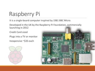
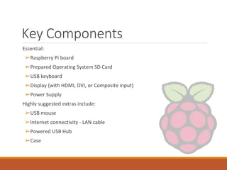
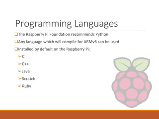
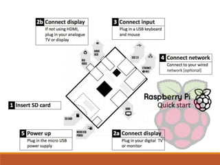
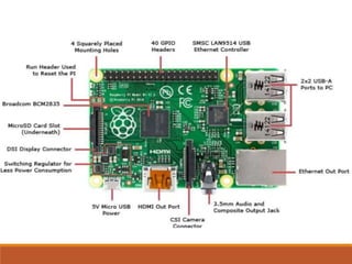
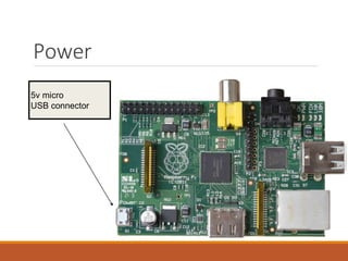
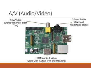
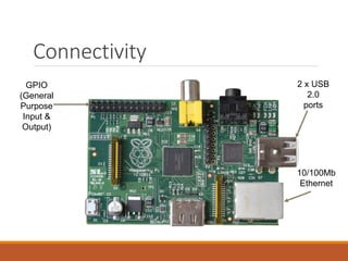
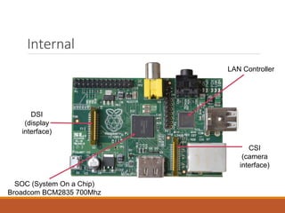
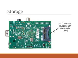
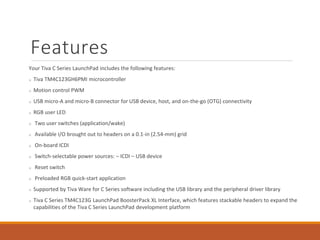
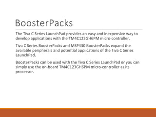
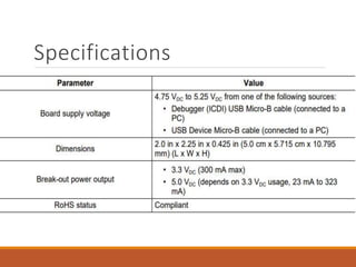
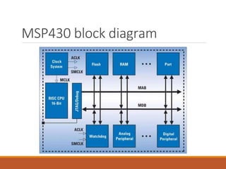
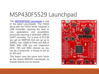
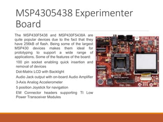
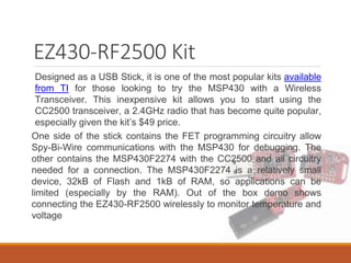
Embedded
Application
Development
BY:- RAHUL RANJAN (1507859)
https://www.facebook.com/aakash416/
http://avirusraj.blogspot.in
POWERED BY VIRUS
Introduction To Embedded
System
An embedded system is a computer system with a dedicated
function within a larger mechanical or electrical system, often
with real-time computing constraints.
It is embedded as part of a complete device often including
hardware and mechanical parts. Embedded systems control
many devices in common use today.
Ninety-eight percent of all microprocessors are manufactured as
components of embedded systems.
Embedded
application
development
platforms
1) Arduino
2) Raspberry Pie
3) Tiva C Series
4) MSP430
Arduino
Arduino is a prototype platform (open-source) based on an easy-to-use
hardware and software.
It consists of a circuit board, which can be programmed (referred to as a
micro-controller ) and a ready-made software called Arduino IDE
(Integrated Development Environment), which is used to write and
upload the computer code to the physical board.
The key features are
Arduino boards are able to read analog or digital input signals from
different sensors and turn it into an output such as activating a motor,
turning LED on/off, connect to the cloud and many other actions.
You can control your board functions by sending a set of instructions to the
micro-controller on the board via Arduino IDE (referred to as uploading
software).
Unlike most previous programmable circuit boards, Arduino does not need
an extra piece of hardware (called a programmer) in order to load a new
code onto the board. You can simply use a USB cable.
Additionally, the Arduino IDE uses a simplified version of C++, making it
easier to learn to program.
Finally, Arduino provides a standard form factor that breaks the functions
of the micro-controller into a more accessible package.
Board types
Various kinds of Arduino boards are available depending on different
micro-controllers used. However, all Arduino boards have one thing in
common: they are programmed through the Arduino IDE.
The differences are based on the number of inputs and outputs (the
number of sensors, LEDs, and buttons you can use on a single board),
speed, operating voltage, form factor etc. Some boards are designed to
be embedded and have no programming interface (hardware), which
you would need to buy separately. Some can run directly from a 3.7V
battery, others need at least 5V.
Arduino boards based on ATMEGA328 micro-controller
Arduino boards based on ATMEGA32u4 micro-controller
Arduino boards based on ATMEGA2560 micro-controller
Arduino uno
We will study the Arduino UNO board because it is the most popular
board in the Arduino board family. In addition, it is the best board to
get started with electronics and coding. Some boards look a bit
different from the one given below, but most Arduino have majority of
these components in common.
Description of board
❑ Pin1 - Power USB - Arduino board can be powered by using the USB cable from your
computer. All you need to do is connect the USB cable to the USB connection (1).
❑ Pin2 - Power (Barrel Jack) - Arduino boards can be powered directly from the AC
mains power supply by connecting it to the Barrel Jack (2).
❑ Pin3 - Voltage Regulator - The function of the voltage regulator is to control the
voltage given to the Arduino board and stabilise the DC voltages used by the
processor and other elements.
❑ Pin4 - Crystal Oscillator - The crystal oscillator helps Arduino in dealing with time
issues. How does Arduino calculate time? The answer is, by using the crystal
oscillator. The number printed on top of the Arduino crystal is 16.000H9H. It tells us
that the frequency is 16,000,000 Hertz or 16 MHz.
❑ Pin5 - Arduino Reset - You can reset your Arduino board, i.e., start your program from
the beginning. You can reset the UNO board in two ways. First, by using the reset
button (17) on the board. Second, you can connect an external reset button to the
Arduino pin labelled RESET (5).
Raspberry Pi
It is a single-board computer inspired by 1981 BBC Micro.
Developed in the UK by the Raspberry Pi Foundation, commercially
launching in 2012
Credit Card sized
Plugs into a TV or monitor
Inexpensive ~$35 each
Raspberry Pie
❑The “Raspberry” derives is an homage to early computer companies
being named after fruit, like Apple, Tangerine Computer Systems,
Apricot Computers, and Acorn (which inspired the microcomputer’s
design). The “Pi” derives from the original idea to make a small
computer to run only the Python programming language.
❑The first commercially available Raspberry Pi unit was launched on
February 19, 2012, and sales started ten days later. This version
could run Linux-based desktop operating systems, and featured 256MB
of RAM, one USB port, and no Ethernet port. This was named the Model
A.
Key Components
Essential:
➢Raspberry Pi board
➢Prepared Operating System SD Card
➢USB keyboard
➢Display (with HDMI, DVI, or Composite input)
➢Power Supply
Highly suggested extras include:
➢USB mouse
➢Internet connectivity - LAN cable
➢Powered USB Hub
➢Case
Programming Languages
❑The Raspberry Pi Foundation recommends Python
❑Any language which will compile for ARMv6 can be used
❑Installed by default on the Raspberry Pi:
➢C
➢C++
➢Java
➢Scratch
➢Ruby
5v micro
USB connector
Power
A/V (Audio/Video)
RCA Video
(works with most older
TVs)
3.5mm Audio
Standard
headphone socket
HDMI Audio & Video
(works with modern TVs and monitors)
Connectivity
GPIO
(General
Purpose
Input &
Output)
10/100Mb
Ethernet
2 x USB
2.0
ports
Internal
DSI
(display
interface)
SOC (System On a Chip)
Broadcom BCM2835 700Mhz
CSI
(camera
interface)
LAN Controller
Storage
SD Card Slot
(supports SD
cards up to
32GB)
Raspbian
Raspbian is a Debian-based computer operating
system for Raspberry Pi.
Since 2015 it has been officially provided by the Raspberry Pi
Foundation as the primary operating system for the family of Raspberry
Pi single-board computers.
The initial build was completed in June 2012 and it is still under active
development. It is highly optimised for the Raspberry Pi line's low-
performance ARM CPUs.
It uses PIXEL, Pi Improved X windows Environment, Lightweight as its
main desktop environment as of the latest update
Pinout
Applications
Desktop PC
Wireless Printer Server
Media Centre
Retro Gaming Machine
Robot Controller
FM Radio Station (over a short distance)
Web Server
Motion Capture Security System
Network Monitoring Tool
Home Automation System (coupled with Arduino)
TIVA
C
SERIES
Tiva C Series
The Tiva™ C Series TM4C123G LaunchPad Evaluation Board (EK-
TM4C123GXL) is a low-cost evaluation platform for ARM® Cortex™-M4F-
based micro-controllers.
The Tiva C Series LaunchPad design highlights the TM4C123GH6PMI
micro-controller USB 2.0 device interface, hibernation module, and
motion control pulse-width modulator (MC PWM) module. The Tiva C
Series LaunchPad also features programmable user buttons and an RGB
LED for custom applications.
The stackable headers of the Tiva C Series TM4C123G LaunchPad
BoosterPack XL interface demonstrate how easy it is to expand the
functionality of the Tiva C Series LaunchPad when interfacing to other
peripherals on many existing BoosterPack add-on boards as well as future
products. Figure 1-1 shows a photo of the Tiva C Series LaunchPad.
Kit Contents
The Tiva C Series TM4C123G LaunchPad Evaluation Kit contains the
following items:
➢Tiva C Series LaunchPad Evaluation Board (EK-TM4C123GXL)
➢On-board In-Circuit Debug Interface (ICDI)
➢USB micro-B plug to USB-A plug cable
Using the Tiva C Series
LaunchPad
The recommended steps for using the Tiva C Series TM4C123G LaunchPad Evaluation Kit are:
1) Follow the README First document included in the kit. The README First document
will help you get the Tiva C Series LaunchPad up and running in minutes. See the
Tiva C Series LaunchPad web page for additional information to help you get
started.
2) Experiment with LaunchPad BoosterPacks. A selection of Tiva C Series BoosterPacks
and compatible MSP430™ BoosterPacks can be found at the TI MCU LaunchPad
web page.
3) Take your first step toward developing an application with Project 0 using your preferred
ARM tool-chain and the Tiva C Series Tiva Ware Peripheral Driver Library. Software
applications are loaded using the on-board In-Circuit Debug Interface (ICDI). The
Tiva Ware for C Series Peripheral Driver Library Software Reference Manual
contains specific information on software structure and function.
4) Customise and integrate the hardware to suit an end application. This user's manual is
an important reference for understanding circuit operation and completing
hardware modification.
Features
Your Tiva C Series LaunchPad includes the following features:
Tiva TM4C123GH6PMI microcontroller
Motion control PWM
USB micro-A and micro-B connector for USB device, host, and on-the-go (OTG) connectivity
RGB user LED
Two user switches (application/wake)
Available I/O brought out to headers on a 0.1-in (2.54-mm) grid
On-board ICDI
Switch-selectable power sources: – ICDI – USB device
Reset switch
Preloaded RGB quick-start application
Supported by Tiva Ware for C Series software including the USB library and the peripheral driver library
Tiva C Series TM4C123G LaunchPad BoosterPack XL Interface, which features stackable headers to expand the
capabilities of the Tiva C Series LaunchPad development platform
BoosterPacks
The Tiva C Series LaunchPad provides an easy and inexpensive way to
develop applications with the TM4C123GH6PM micro-controller.
Tiva C Series BoosterPacks and MSP430 BoosterPacks expand the
available peripherals and potential applications of the Tiva C Series
LaunchPad.
BoosterPacks can be used with the Tiva C Series LaunchPad or you can
simply use the on-board TM4C123GH6PM micro-controller as its
processor.
Specifications
MSP430
MSP430 Development
hardware
The MSP430 contains several families, from the
low cost Value family to the most advanced
F6xx family. Each family is usually targeted at a set
of applications and contains a certain mix of
peripherals. In a family, however, devices vary as
far as the amount of Flash and RAM available.
It is not unusual to develop using relatively large
devices in a family, only to migrate down to reduce
costs. Because of this, the tutorial will end up
discussing several platforms, but will attempt to
cover the lowest denominator first to make it
accessible.
The MSP430 Launchpad is the most accessible
MSP430 platform and although the devices
supported do not have all the peripherals of some
of the mode advanced MSP430, it does cover so
many peripherals that it makes it an ideal platform
for starting.
MSP430 Development
hardware
➢ The MSP430 Launchpad is an easy way to get started with the MSP430.
For a long time the board was sold at a promotional cost of $4.30,
although it’s now available for $9.99. Still, the cost makes it difficult to
say no. You can get one from TI’s Website.
➢ The board contains a DIP socket capable of accepting most variants of
the MSP430Gxx family. The most common device used is the
MSP430G2553, which is a part running up to 16MHz with 16kB of flash
and 512B of RAM. The USB connectivity on the board allows both
programming with the on-board JTAG programmer, as well as UART
communications for data transfer.
➢ The board can be augmented with booster packs designed by TI and
third parties that enable Wireless Communications, Wi-Fi, Batteries,
Displays, and other elements.
Key features
❑ Low power consumption:
▪ 0.1 μA for RAM data retention;
▪ 0.8 μA for real time clock mode operation;
▪ 250 μA/MIPS at active operation.
❑ Low operation voltage (from 1.8 V to 3.6 V).
▪ < 1 μs clock start-up.
▪ < 50 nA port leakage.
❑ Zero-power Brown-Out Reset (BOR).
❑ On-chip analogue devices:
▪ 10/12/16-bit Analogue-to-Digital Converter (ADC);
▪ 12-bit dual Digital-to-Analogue Converter (DAC);
▪ Comparator-gated timers;
▪ Operational Amplifiers (OP Amps);
▪ Supply Voltage Supervisor (SVS).
Key features
❑ 16 bit RISC CPU:
▪ Instructions processing on either bits, bytes or words;
▪ Compact core design reduces power consumption and cost;
▪ Compiler efficient;
▪ 27 core instructions;
▪ 7 addressing modes;
▪ Extensive vectored-interrupt capability.
❑ Flexibility:
▪ Up to 256 kB In-System Programmable (ISP) Flash;
▪ Up to 100 pin options;
▪ USART, I2C, Timers;
▪ LCD driver;
▪ Embedded emulation.
MSP430 block diagram
MSP430F5529 Launchpad
This MSP430F5529 Launchpad is one
of the latest Launchpads. The F5529
along with the F55xx family integrate a
USB Controller, opening the door to
new applications and possibilities
previously requiring a dedicated USB to
UART converter. For a price of $12.99
you get an MSP430 that can go up to
25MHz, has 128kB of Flash and 8kB of
RAM. With USB you can implement
CDC, HID and MSC classes so you
can be a serial port, a mouse or act as
an SD card.
This board uses the same form factor
as the classic MSP430 Launchpad, so
booster boards can be reused.
MSP4305438 Experimenter
Board
The MSP430F5438 and MSP430F5438A are
quite popular devices due to the fact that they
have 256kB of flash. Being some of the largest
MSP430 devices makes them ideal for
prototyping to support a wide range of
applications. Some of the features of the board:
100 pin socket enabling quick insertion and
removal of devices
Dot-Matrix LCD with Backlight
Audio Jack output with on-board Audio Amplifier
3-Axis Analog Accelerometer
5 position Joystick for navigation
EM Connector headers supporting TI Low
Power Transceiver Modules
EZ430-RF2500 Kit
Designed as a USB Stick, it is one of the most popular kits available
from TI for those looking to try the MSP430 with a Wireless
Transceiver. This inexpensive kit allows you to start using the
CC2500 transceiver, a 2.4GHz radio that has become quite popular,
especially given the kit’s $49 price.
One side of the stick contains the FET programming circuitry allow
Spy-Bi-Wire communications with the MSP430 for debugging. The
other contains the MSP430F2274 with the CC2500 and all circuitry
needed for a connection. The MSP430F2274 is a relatively small
device, 32kB of Flash and 1kB of RAM, so applications can be
limited (especially by the RAM). Out of the box demo shows
connecting the EZ430-RF2500 wirelessly to monitor temperature and
voltage
JTAG Programmer
Programming, Debugging and Flashing the MSP430 is done via the
JTAG interface, or its pin reduced version called Spy-Bi-Wire.
Although this JTAG is based on the IEEE 1149.1 Joint Test Action
Group (JTAG) specification, TI has made modifications which mean
that a MSP430 specific programmer must be used. The USB-FET
is probably the most common programmer. A parallel port version
was once available but has since become extinct given the
disappearance of parallel ports and the emergence of USB.
The USB FET programmer is supported by practically all compilers
and IDEs, including Code Composer Studio, IAR Workbench and
Open source tools. The USB-FET programmer can be purchased
from TI.
Embedded application development

Embedded application development

  • 2.
    Embedded Application Development BY:- RAHUL RANJAN(1507859) https://www.facebook.com/aakash416/ http://avirusraj.blogspot.in POWERED BY VIRUS
  • 3.
    Introduction To Embedded System Anembedded system is a computer system with a dedicated function within a larger mechanical or electrical system, often with real-time computing constraints. It is embedded as part of a complete device often including hardware and mechanical parts. Embedded systems control many devices in common use today. Ninety-eight percent of all microprocessors are manufactured as components of embedded systems.
  • 4.
  • 6.
    Arduino Arduino is aprototype platform (open-source) based on an easy-to-use hardware and software. It consists of a circuit board, which can be programmed (referred to as a micro-controller ) and a ready-made software called Arduino IDE (Integrated Development Environment), which is used to write and upload the computer code to the physical board.
  • 7.
    The key featuresare Arduino boards are able to read analog or digital input signals from different sensors and turn it into an output such as activating a motor, turning LED on/off, connect to the cloud and many other actions. You can control your board functions by sending a set of instructions to the micro-controller on the board via Arduino IDE (referred to as uploading software). Unlike most previous programmable circuit boards, Arduino does not need an extra piece of hardware (called a programmer) in order to load a new code onto the board. You can simply use a USB cable. Additionally, the Arduino IDE uses a simplified version of C++, making it easier to learn to program. Finally, Arduino provides a standard form factor that breaks the functions of the micro-controller into a more accessible package.
  • 8.
    Board types Various kindsof Arduino boards are available depending on different micro-controllers used. However, all Arduino boards have one thing in common: they are programmed through the Arduino IDE. The differences are based on the number of inputs and outputs (the number of sensors, LEDs, and buttons you can use on a single board), speed, operating voltage, form factor etc. Some boards are designed to be embedded and have no programming interface (hardware), which you would need to buy separately. Some can run directly from a 3.7V battery, others need at least 5V. Arduino boards based on ATMEGA328 micro-controller Arduino boards based on ATMEGA32u4 micro-controller Arduino boards based on ATMEGA2560 micro-controller
  • 9.
    Arduino uno We willstudy the Arduino UNO board because it is the most popular board in the Arduino board family. In addition, it is the best board to get started with electronics and coding. Some boards look a bit different from the one given below, but most Arduino have majority of these components in common.
  • 11.
    Description of board ❑Pin1 - Power USB - Arduino board can be powered by using the USB cable from your computer. All you need to do is connect the USB cable to the USB connection (1). ❑ Pin2 - Power (Barrel Jack) - Arduino boards can be powered directly from the AC mains power supply by connecting it to the Barrel Jack (2). ❑ Pin3 - Voltage Regulator - The function of the voltage regulator is to control the voltage given to the Arduino board and stabilise the DC voltages used by the processor and other elements. ❑ Pin4 - Crystal Oscillator - The crystal oscillator helps Arduino in dealing with time issues. How does Arduino calculate time? The answer is, by using the crystal oscillator. The number printed on top of the Arduino crystal is 16.000H9H. It tells us that the frequency is 16,000,000 Hertz or 16 MHz. ❑ Pin5 - Arduino Reset - You can reset your Arduino board, i.e., start your program from the beginning. You can reset the UNO board in two ways. First, by using the reset button (17) on the board. Second, you can connect an external reset button to the Arduino pin labelled RESET (5).
  • 13.
    Raspberry Pi It isa single-board computer inspired by 1981 BBC Micro. Developed in the UK by the Raspberry Pi Foundation, commercially launching in 2012 Credit Card sized Plugs into a TV or monitor Inexpensive ~$35 each
  • 14.
    Raspberry Pie ❑The “Raspberry”derives is an homage to early computer companies being named after fruit, like Apple, Tangerine Computer Systems, Apricot Computers, and Acorn (which inspired the microcomputer’s design). The “Pi” derives from the original idea to make a small computer to run only the Python programming language. ❑The first commercially available Raspberry Pi unit was launched on February 19, 2012, and sales started ten days later. This version could run Linux-based desktop operating systems, and featured 256MB of RAM, one USB port, and no Ethernet port. This was named the Model A.
  • 15.
    Key Components Essential: ➢Raspberry Piboard ➢Prepared Operating System SD Card ➢USB keyboard ➢Display (with HDMI, DVI, or Composite input) ➢Power Supply Highly suggested extras include: ➢USB mouse ➢Internet connectivity - LAN cable ➢Powered USB Hub ➢Case
  • 16.
    Programming Languages ❑The RaspberryPi Foundation recommends Python ❑Any language which will compile for ARMv6 can be used ❑Installed by default on the Raspberry Pi: ➢C ➢C++ ➢Java ➢Scratch ➢Ruby
  • 19.
  • 20.
    A/V (Audio/Video) RCA Video (workswith most older TVs) 3.5mm Audio Standard headphone socket HDMI Audio & Video (works with modern TVs and monitors)
  • 21.
  • 22.
    Internal DSI (display interface) SOC (System Ona Chip) Broadcom BCM2835 700Mhz CSI (camera interface) LAN Controller
  • 23.
    Storage SD Card Slot (supportsSD cards up to 32GB)
  • 24.
    Raspbian Raspbian is aDebian-based computer operating system for Raspberry Pi. Since 2015 it has been officially provided by the Raspberry Pi Foundation as the primary operating system for the family of Raspberry Pi single-board computers. The initial build was completed in June 2012 and it is still under active development. It is highly optimised for the Raspberry Pi line's low- performance ARM CPUs. It uses PIXEL, Pi Improved X windows Environment, Lightweight as its main desktop environment as of the latest update
  • 25.
  • 26.
    Applications Desktop PC Wireless PrinterServer Media Centre Retro Gaming Machine Robot Controller FM Radio Station (over a short distance) Web Server Motion Capture Security System Network Monitoring Tool Home Automation System (coupled with Arduino)
  • 27.
  • 28.
    Tiva C Series TheTiva™ C Series TM4C123G LaunchPad Evaluation Board (EK- TM4C123GXL) is a low-cost evaluation platform for ARM® Cortex™-M4F- based micro-controllers. The Tiva C Series LaunchPad design highlights the TM4C123GH6PMI micro-controller USB 2.0 device interface, hibernation module, and motion control pulse-width modulator (MC PWM) module. The Tiva C Series LaunchPad also features programmable user buttons and an RGB LED for custom applications. The stackable headers of the Tiva C Series TM4C123G LaunchPad BoosterPack XL interface demonstrate how easy it is to expand the functionality of the Tiva C Series LaunchPad when interfacing to other peripherals on many existing BoosterPack add-on boards as well as future products. Figure 1-1 shows a photo of the Tiva C Series LaunchPad.
  • 30.
    Kit Contents The TivaC Series TM4C123G LaunchPad Evaluation Kit contains the following items: ➢Tiva C Series LaunchPad Evaluation Board (EK-TM4C123GXL) ➢On-board In-Circuit Debug Interface (ICDI) ➢USB micro-B plug to USB-A plug cable
  • 31.
    Using the TivaC Series LaunchPad The recommended steps for using the Tiva C Series TM4C123G LaunchPad Evaluation Kit are: 1) Follow the README First document included in the kit. The README First document will help you get the Tiva C Series LaunchPad up and running in minutes. See the Tiva C Series LaunchPad web page for additional information to help you get started. 2) Experiment with LaunchPad BoosterPacks. A selection of Tiva C Series BoosterPacks and compatible MSP430™ BoosterPacks can be found at the TI MCU LaunchPad web page. 3) Take your first step toward developing an application with Project 0 using your preferred ARM tool-chain and the Tiva C Series Tiva Ware Peripheral Driver Library. Software applications are loaded using the on-board In-Circuit Debug Interface (ICDI). The Tiva Ware for C Series Peripheral Driver Library Software Reference Manual contains specific information on software structure and function. 4) Customise and integrate the hardware to suit an end application. This user's manual is an important reference for understanding circuit operation and completing hardware modification.
  • 32.
    Features Your Tiva CSeries LaunchPad includes the following features: Tiva TM4C123GH6PMI microcontroller Motion control PWM USB micro-A and micro-B connector for USB device, host, and on-the-go (OTG) connectivity RGB user LED Two user switches (application/wake) Available I/O brought out to headers on a 0.1-in (2.54-mm) grid On-board ICDI Switch-selectable power sources: – ICDI – USB device Reset switch Preloaded RGB quick-start application Supported by Tiva Ware for C Series software including the USB library and the peripheral driver library Tiva C Series TM4C123G LaunchPad BoosterPack XL Interface, which features stackable headers to expand the capabilities of the Tiva C Series LaunchPad development platform
  • 33.
    BoosterPacks The Tiva CSeries LaunchPad provides an easy and inexpensive way to develop applications with the TM4C123GH6PM micro-controller. Tiva C Series BoosterPacks and MSP430 BoosterPacks expand the available peripherals and potential applications of the Tiva C Series LaunchPad. BoosterPacks can be used with the Tiva C Series LaunchPad or you can simply use the on-board TM4C123GH6PM micro-controller as its processor.
  • 34.
  • 35.
  • 36.
    MSP430 Development hardware The MSP430contains several families, from the low cost Value family to the most advanced F6xx family. Each family is usually targeted at a set of applications and contains a certain mix of peripherals. In a family, however, devices vary as far as the amount of Flash and RAM available. It is not unusual to develop using relatively large devices in a family, only to migrate down to reduce costs. Because of this, the tutorial will end up discussing several platforms, but will attempt to cover the lowest denominator first to make it accessible. The MSP430 Launchpad is the most accessible MSP430 platform and although the devices supported do not have all the peripherals of some of the mode advanced MSP430, it does cover so many peripherals that it makes it an ideal platform for starting.
  • 37.
    MSP430 Development hardware ➢ TheMSP430 Launchpad is an easy way to get started with the MSP430. For a long time the board was sold at a promotional cost of $4.30, although it’s now available for $9.99. Still, the cost makes it difficult to say no. You can get one from TI’s Website. ➢ The board contains a DIP socket capable of accepting most variants of the MSP430Gxx family. The most common device used is the MSP430G2553, which is a part running up to 16MHz with 16kB of flash and 512B of RAM. The USB connectivity on the board allows both programming with the on-board JTAG programmer, as well as UART communications for data transfer. ➢ The board can be augmented with booster packs designed by TI and third parties that enable Wireless Communications, Wi-Fi, Batteries, Displays, and other elements.
  • 38.
    Key features ❑ Lowpower consumption: ▪ 0.1 μA for RAM data retention; ▪ 0.8 μA for real time clock mode operation; ▪ 250 μA/MIPS at active operation. ❑ Low operation voltage (from 1.8 V to 3.6 V). ▪ < 1 μs clock start-up. ▪ < 50 nA port leakage. ❑ Zero-power Brown-Out Reset (BOR). ❑ On-chip analogue devices: ▪ 10/12/16-bit Analogue-to-Digital Converter (ADC); ▪ 12-bit dual Digital-to-Analogue Converter (DAC); ▪ Comparator-gated timers; ▪ Operational Amplifiers (OP Amps); ▪ Supply Voltage Supervisor (SVS).
  • 39.
    Key features ❑ 16bit RISC CPU: ▪ Instructions processing on either bits, bytes or words; ▪ Compact core design reduces power consumption and cost; ▪ Compiler efficient; ▪ 27 core instructions; ▪ 7 addressing modes; ▪ Extensive vectored-interrupt capability. ❑ Flexibility: ▪ Up to 256 kB In-System Programmable (ISP) Flash; ▪ Up to 100 pin options; ▪ USART, I2C, Timers; ▪ LCD driver; ▪ Embedded emulation.
  • 40.
  • 41.
    MSP430F5529 Launchpad This MSP430F5529Launchpad is one of the latest Launchpads. The F5529 along with the F55xx family integrate a USB Controller, opening the door to new applications and possibilities previously requiring a dedicated USB to UART converter. For a price of $12.99 you get an MSP430 that can go up to 25MHz, has 128kB of Flash and 8kB of RAM. With USB you can implement CDC, HID and MSC classes so you can be a serial port, a mouse or act as an SD card. This board uses the same form factor as the classic MSP430 Launchpad, so booster boards can be reused.
  • 42.
    MSP4305438 Experimenter Board The MSP430F5438and MSP430F5438A are quite popular devices due to the fact that they have 256kB of flash. Being some of the largest MSP430 devices makes them ideal for prototyping to support a wide range of applications. Some of the features of the board: 100 pin socket enabling quick insertion and removal of devices Dot-Matrix LCD with Backlight Audio Jack output with on-board Audio Amplifier 3-Axis Analog Accelerometer 5 position Joystick for navigation EM Connector headers supporting TI Low Power Transceiver Modules
  • 43.
    EZ430-RF2500 Kit Designed asa USB Stick, it is one of the most popular kits available from TI for those looking to try the MSP430 with a Wireless Transceiver. This inexpensive kit allows you to start using the CC2500 transceiver, a 2.4GHz radio that has become quite popular, especially given the kit’s $49 price. One side of the stick contains the FET programming circuitry allow Spy-Bi-Wire communications with the MSP430 for debugging. The other contains the MSP430F2274 with the CC2500 and all circuitry needed for a connection. The MSP430F2274 is a relatively small device, 32kB of Flash and 1kB of RAM, so applications can be limited (especially by the RAM). Out of the box demo shows connecting the EZ430-RF2500 wirelessly to monitor temperature and voltage
  • 44.
    JTAG Programmer Programming, Debuggingand Flashing the MSP430 is done via the JTAG interface, or its pin reduced version called Spy-Bi-Wire. Although this JTAG is based on the IEEE 1149.1 Joint Test Action Group (JTAG) specification, TI has made modifications which mean that a MSP430 specific programmer must be used. The USB-FET is probably the most common programmer. A parallel port version was once available but has since become extinct given the disappearance of parallel ports and the emergence of USB. The USB FET programmer is supported by practically all compilers and IDEs, including Code Composer Studio, IAR Workbench and Open source tools. The USB-FET programmer can be purchased from TI.