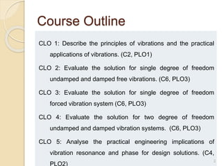
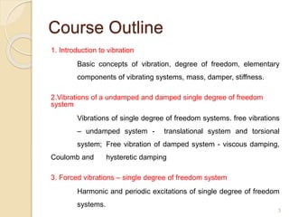
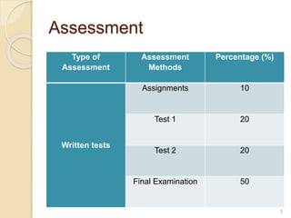
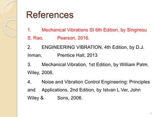
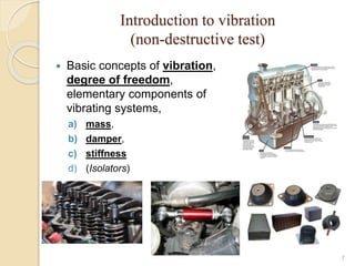
EM418
MECHANICAL VIBRATIONS
1
Course Outline
CLO 1: Describe the principles of vibrations and the practical
applications of vibrations. (C2, PLO1)
CLO 2: Evaluate the solution for single degree of freedom
undamped and damped free vibrations. (C6, PLO3)
CLO 3: Evaluate the solution for single degree of freedom
forced vibration system (C6, PLO3)
CLO 4: Evaluate the solution for two degree of freedom
undamped and damped vibration systems. (C6, PLO3)
CLO 5: Analyse the practical engineering implications of
vibration resonance and phase for design solutions. (C4,
PLO2)
2
Course Outline
1. Introduction to vibration
Basic concepts of vibration, degree of freedom, elementary
components of vibrating systems, mass, damper, stiffness.
2.Vibrations of a undamped and damped single degree of freedom
system
Vibrations of single degree of freedom systems. free vibrations
– undamped system - translational system and torsional
system; Free vibration of damped system - viscous damping,
Coulomb and hysteretic damping
3. Forced vibrations – single degree of freedom system
Harmonic and periodic excitations of single degree of freedom
systems.
3
Course Outline
4.Two degree-of-freedom systems
Free and harmonically excited vibrations, vibration
neutralizer and applications
5. Vibration resonance and phase for design solutions
Vibration nomograph and vibration criteria, reduction of
vibration at the source, balancing of rotating
machines, whirling of rotating shafts, control of vibration, control
of natural frequencies, vibration isolation. Graphical
methods – phase plane representation, phase velocity, method
of constructing trajectories, obtaining time solution from phase plane
trajectories.
4
Assessment
Type of
Assessment
Assessment
Methods
Percentage (%)
Written tests
Assignments 10
Test 1 20
Test 2 20
Final Examination 50
5
References
1. Mechanical Vibrations SI 6th Edition, by Singiresu
S. Rao, Pearson, 2016.
2. ENGINEERING VIBRATION, 4th Edition, by D.J.
Inman, Prentice Hall, 2013
3. Mechanical Vibration, 1st Edition, by William Palm,
Wiley, 2006.
4. Noise and Vibration Control Engineering: Principles
and Applications, 2nd Edition, by Istvan L Ver, John
Wiley & Sons, 2006.
6
Introduction to vibration
(non-destructive test)
 Basic concepts of vibration,
degree of freedom,
elementary components of
vibrating systems,
a) mass,
b) damper,
c) stiffness
d) (Isolators)
7
Vibration - Introduction
 Any motion that repeats itself after an interval of
time is called vibration or oscillation.
 The theory of vibration deals with the study of
oscillatory motions of bodies and the forces
associated with them.
8
Vibration - Introduction
Example:
Swinging of a pendulum,
Motion of a plucked string.
 Human activities involve vibration in one form or
other (Can you list some of them?)
9
Vibration – Introduction
vibrations in human activities
 We hear because our eardrums vibrate,
 We see because light waves undergo vibration,
 Breathing associated with the vibration of lungs,
 Walking involves periodic oscillatory motion of
legs and hands.
10
Brief History of Vibration
11
Brief History of Vibration
12
Brief History of Vibration
13
Brief History of Vibration
14
Brief History of Vibration
(1564 – 1642) Galileo Galilei
- Founder of modern experimental science.
- Started experimenting on simple pendulum.
- Studied the behavior of a simple pendulum (observed
pendulum movement of a lamp).
- Described the dependency of the frequency of vibration
on the length of a simple pendulum.
- Described resonance, frequency, length, tension and
density of a vibrating stretched string.
15
Brief History of Vibration
Sir Isaac Newton (1642-1727) derived the equation of
motion of a vibrating body.
The theoretical solution of the problem of the vibrating
string was found in 1713 by the English mathematician
Brook Taylor.
The procedure of Taylor was perfected through the
introduction of partial derivatives in the equations of
motion by Daniel Bernoulli, Jean D’Alembert and
Leonard Euler.
16
Partial Differential
17
Brief History of Vibration
 The analytical solution of the vibrating string was
presented by Joseph Lagrange.
 Rayleigh presented the method of finding the
fundamental frequency of vibration of a
conservative system by making use of the
principle of conservation of energy (Rayleigh’s
method).
18
Brief History of Vibration
 Frahm investigated the importance of torsional
vibration study in the design of the propeller shafts
of steamships.
 Stephen Timoshenko presented an improved
theory of vibration of beams.
19
Time Spectrum vs Frequency
Spectrum
20
Time Spectrum vs Frequency
Spectrum
21
3.34 3.342 3.344 3.346 3.348 3.35 3.352 3.354 3.356
x 10
4
-0.04
-0.03
-0.02
-0.01
0
0.01
0.02
0.03
0.04
0.05
Time/44100 (sec)
Amplitude
Flute Sample
0 1000 2000 3000 4000 5000 6000 7000
0
100
200
300
400
500
600
700
800
900
1000
Frequency (Hz)
Amplitude
2.82 2.84 2.86 2.88 2.9 2.92
x 10
4
-0.06
-0.04
-0.02
0
0.02
0.04
0.06
0.08
Time (x44100)
Amplitude
Piano Sample
0 500 1000 1500
2
4
6
8
10
12
x 10
4
Frequency (Hz)
Amplitude
Frequency Spectrum of Piano
Vibration – Introduction
Importance of the Study of Vibration
◦ Most prime movers have vibrational problems
due to inherent unbalance in the engine.
◦ Wheel of some locomotive rise more than
centimeter off the track at high speeds due to
imbalance.
◦ In turbines – vibration cause spectacular
mechanical failure.
22
Vibration – Introduction
Importance of the Study of Vibration
◦ Vibration causes more rapid wear of machine
parts such as bearings and gears and also causes
the excessive noises.
◦ In machines, vibration can loosen fasteners such
as nuts.
◦ In metal cutting processes, vibration cause
chatter, which leads to a poor surface finish.
23
Vibration – Introduction
Importance of the Study of Vibration
◦ Vibration causes fatigue failure of structures like
aircraft fuselage, machine components like
crankshaft.
◦ Vibration causes severe damages due to
resonance; collapsing of bridges, damages in
transmission lines, damages to offshore
structures.
24
Vibration – Introduction
Importance of the Study of Vibration
 Vibration causes malfunctioning of sensitive
Instruments/ systems; payloads from vibration
of launching rockets, high precision machining,
micromachines & microassembly
25
Loss of accuracy of work-piece:
Shifting of tool position due to
vibration of cutting tool
26
Consider how a CNC operates (which
component is moving? workpiece or cutting
tool?
This phenomenon is generally referred
as 'chatter vibration'.
27
Fatigue Failure – broken
camshaft
28
Space craft – isolation of
payload
29
Space craft – isolation of
payload
30
Vibration – Introduction
Importance of the Study of Vibration
 In spite of its detrimental effects, vibration can
be utilized profitably in several industrial and
consumer applications.
For example,
 Vibratory conveyors, hoppers, compactors,
washing machines, electric toothbrushes,
dentist’s drills, clocks, electric massaging units.
31
Basic Concepts of Vibration
 It involves the transfer of potential energy to
kinetic energy and vice versa.
 If the system is damped, some energy is
dissipated in each cycle of vibration and must be
replaced by an external source if a state of steady
vibration is to be maintained.
32
Basic Concepts of Vibration
An example
showing cause
of vibration;
conversion of
potential energy
to kinetic
energy.
33
Basic Concepts of Vibration – Degrees of
freedom
Degree of Freedom (d.o.f.) is min. no. of independent
coordinates required to determine completely the
positions of all parts of a system at any instant of
time.
34
Example of single degree-of-freedom
system
The motion of the pendulum can be stated either
in  or x and y in Cartesian coordinates.
35
Example of single degree-of-freedom system
36
Example of two degree-of-freedom system
37
Example of three degree-of-freedom system
38
Example of Infinite number of degrees of
freedom system
 Infinite number of degrees of freedom system are
termed continuous or distributed systems.
 Finite number of degrees of freedom are termed
discrete or lumped parameter systems.
 More accurate results obtained by increasing number
of degrees of freedom.
39
Classification of Vibration
 Free Vibration:
A system is left to vibrate on its own after an initial
disturbance and no external force acts on the system.
Ex. simple pendulum
 Forced Vibration:
A system that is subjected to a repeating external force.
Ex. oscillation arises from diesel engines
40
Classification of Vibration
 Resonance occurs when the frequency of the
external force coincides with one of the natural
frequencies of the system.
 It causes a large oscillations.
 The failure of major structures such as bridges, or
airplane wings is an awesome possibility under
resonance.
41
Classification of Vibration
 Undamped Vibration:
When no energy is lost or dissipated in friction or other
resistance during oscillations.
In many physical systems, the amount of damping is so small
that it can be disregarded for most engineering purposes.
 Damped Vibration:
When any energy is lost or dissipated in friction or other
resistance during oscillations
42
Classification of Vibration
Note:
 Calculations for natural frequencies are generally made on
the basis of no damping.
 On the other hand, damping is of great importance in
limiting the amplitude of oscillation at resonance.
43
Classification of Vibration
 Linear Vibration:
When all basic components of a vibratory system, i.e. the
spring, the mass and the damper behave linearly.
 Nonlinear Vibration:
If any of the components behave nonlinearly, it is called
nonlinear vibration.
Note: For linear system, the principle of superposition
holds, and the mathematical techniques of analysis are
well developed.
44
Classification of Vibration
 Deterministic Vibration:
If the value or magnitude of the excitation (force or motion)
acting on a vibratory system is known at any given time
 Nondeterministic or random Vibration:
When the value of the excitation at a given time cannot be
predicted.
Ex. Wind velocity, road roughness, ground motion during
earthquakes.
45
46
Classification of Vibration - Examples of
deterministic and random excitation
Basic components of a vibrating system
Vibratory System consists of:
1) spring or elasticity
2) mass or inertia
3) damper
 A vibratory system, in general includes a means for storing
potential energy (spring or elasticity), a means for storing
kinetic energy (mass or inertia), and a means by which
energy is gradually lost (damper).
47
Inertia & stiffness
 Inertia is linked with kinetic energy of the system.
 Mass and Moment of Inertia are considered to be
inertia of the system.
 Stiffness is linked to the potential energy inside the
system.
 Linear spring and torsional springs are considered
to be stiffness of the system.
48
Mass
 The mass or inertia element is assumed to be a
rigid body.
 It can gain or lose kinetic energy whenever the
velocity of the body changes.
 According to F=ma, the product of mass and
acceleration is equal to the force applied to the
mass.
49
Mass
 Work is equal to the force multiplied by the
displacement in the direction of the force,
 Work done on a mass is stored in the form of the
mass’s kinetic energy.
50
51
Mathematical model is used to represent the actual
vibrating system
Mass or Inertia Elements
52
Combination of Masses
 Ex. Assume that the mass of
the frame is negligible
compared to the masses of the
floors.
 The masses of various floor
levels represent the mass
elements, and the elasticities of
the vertical members denote the
spring elements.
Mass or Inertia Elements
Exercise 1
Determine the equivalent mass of the system
53
54
The equivalent mass can be assumed to be located at
any point along the bar;
we assume that it is at m1.
Velocities of masses m2 and m3 can be expressed as:
 
18
.
1
1
1
3
3
1
1
2
2 x
l
l
x
x
l
l
x 


 

Exercise 1 - solution
 
19
.
1
1
x
xeq 
 
55
By equating the kinetic energy of three mass system to that
of the equivalent mass system:
 
20
.
1
2
1
2
1
2
1
2
1 2
eq
eq
2
3
3
2
2
2
2
1
1 x
m
x
m
x
m
x
m 


 


 
21
.
1
3
2
1
3
2
2
1
2
1
eq m
l
l
m
l
l
m
m 














Exercise 1 - solution
 Determine the equivalent mass of the system
56
meq = single equivalent translational mass
= translational velocity
= rotational velocity
J0 = mass moment of inertia
Jeq = single equivalent rotational mass
x


Exercise 2
57
1. Equivalent translational mass:
Kinetic energy of the two masses is given by:
Kinetic energy of the equivalent mass is given by:
 
22
.
1
2
1
2
1 2
0
2


 J
x
m
T 

 
23
.
1
2
1 2
eq
eq
eq x
m
T 

Exercise 2 - solution
58
Translational and Rotational Masses Coupled Together
Equivalent rotational mass:
Here, and , equating Teq and T
gives

 
 
eq
R
x 

 
 
 
25
.
1
2
1
2
1
2
1
2
0
eq
2
0
2
2
eq
mR
J
J
or
J
R
m
J



 

 


 
24
.
1
2
0
eq
R
J
m
m 

Since and , equating Teq & T
gives R
x

 
 x
x 
 
eq
Exercise 2 - solution
Exercise 3
 Determine equivalent mass of the rocker arm assembly
with respect to x coordinate.
59
Exercise 3 - solution
60
Exercise 4 – do it yourself
61
Exercise 4 – do it yourself
62
Exercise 4 – do it yourself
63
Exercise 5
64
A cam-follower mechanism is
used to convert the rotary
motion of a shaft into the
oscillating or reciprocating
motion of a valve. The follower
system consists of a pushrod
of mass mp, a rocker arm of
mass mr, and mass moment of
inertia Jr about its C.G., a
valve of mass and a valve
spring of negligible mass.
Find the equivalent mass meq
of this cam-follower system by
assuming the location of meq
as
(i) point A and
(ii) point C.
Exercise 5
65
At point A
At point B,
Spring
 A spring is a type of mechanical link, which in
most applications is assumed to have negligible
mass and damping.
 The most common type of spring is the helical-coil
spring.
 Any elastic or deformable body such as cable, bar,
beam, shaft or plate can be considered as a spring.
66
Spring
Spring force is given by
F = spring force,
k = spring stiffness or spring constant, and
x = deformation (displacement of one end with respect
to the other)
G = modulus of rigidity or shear modulus
J = mass moment of Inertia, l =length
𝑘 =
𝐹
𝑥
67
Spring constant (k) of a rod -
Example
How is k determined?
68
Spring constant (k) of a cantilever
beam - Example
Refer strength of materials book for the deflection and
k of any beam
69
Spring constant (k) of a cantilever beam -
Example
Static deflection of a beam at the free end is
given by:
Spring Constant is given by:
 
6
.
1
3
3
EI
Wl
st 

 
7
.
1
3
3
l
EI
W
k
st



70
W = mg is the weight of the mass m,
E = Young’s Modulus, and
I = moment of inertia of cross-section of beam
Spring Elements - Springs in parallel
If we have n spring constants k1, k2, …, kn in parallel,
then the equivalent spring constant keq is:
 
11
.
1
2
1 ... n
eq k
k
k
k 


 71
Spring Elements - Springs in series
If we have n spring constants k1, k2, …, kn in series,
then the equivalent spring constant keq is:
 
17
.
1
1
...
1
1
1
2
1 n
eq
k
k
k
k




72
Spring constants
73
Spring constants
Linear spring constant 𝑘 =
𝐹
𝑥
Torsional spring constant 𝐾𝑡 =
𝐺𝐽
𝑙
𝑘 =
𝐴𝐸
𝑙
Rod with length l, Area A
and modulus of elasticity E
74
Summary of Spring constants
75
Spring Arrangement Equation
Characteristics
Example Force
Orientation
Force acting parallel
to axis
Involves series
and parallel
loading
𝑘 =
𝑘1. 𝑘2
𝑘1 + 𝑘2
Force acting
perpendicular to axis
Includes Inertia &
Young Modulus
Force acting Torsional
to axis
Includes (polar)
Inertia & Modulus
of Rigidity
𝑘 =
𝐴𝐸
𝑙
𝐾𝑡 =
𝐺𝐽
𝑙
Exercise 1
76
Exercise 1 - solution
77
Exercise 2
78
Determine the torsional spring constant of the speed
propeller steel shaft (G= 80 x 10^9 N/m2) shown in figure.
Exercise 2 - Solution
79
We need to consider the segments 12 and 23 of the shaft as
springs in combination.
From Fig. 1.25, the torque induced at any cross section of the
shaft (such as AA or BB) can be seen to be equal to the torque
applied at the propeller, T.
Hence, the elasticity (springs) corresponding to the two
segments 12 and 23 are to be considered as series springs. The
spring constants of segments 12 and 23 of the shaft (kt12 and
kt23) are given by:
Exercise 2 - Solution
m/rad
-
N
10
9012
.
8
)
3
(
32
)
15
.
0
25
.
0
(
)
10
80
(
32
)
(
6
4
4
9
23
4
23
4
23
23
23
23










l
d
D
G
l
GJ
kt
m/rad
-
N
10
5255
.
25
)
2
(
32
)
2
.
0
3
.
0
(
)
10
80
(
32
)
(
6
4
4
9
12
4
12
4
12
12
12
12










l
d
D
G
l
GJ
kt
80
Exercise 2 - Solution
m/rad
-
N
10
5997
.
6
)
10
9012
.
8
10
5255
.
25
(
)
10
9012
.
8
)(
10
5255
.
25
(
6
6
6
6
6
23
12
23
12










t
t
t
t
t
k
k
k
k
keq
81
Since the springs are in series, Eq.
(1.16) gives
Exercise 3
82
Exercise 3 - solution
83
Exercise 4
84
E = 190 (109)
a = 30 cm
b = 150 cm
t = 2 cm
d = 0.5 cm
L = 150 cm
Exercise 4 -solution
85
Exercise 4 - solution
86
Answer = 3.3 (104) N/m
Exercise 5 – Home work
87
Exercise 5 - solution
88
Exercise 5 - solution
89
Exercise 5 - solution
90
Exercise 6 – home work
 Determine the equivalent spring
constant of a simple pendulum.
91
Exercise 6 - solution
92
Exercise 7
93
Galuminium = 26(109) ; G steel = 80(109)
Answer: 5.548 (106) N.m/rad
Damping
 The mechanism by which the vibrational energy is
gradually converted into heat or sound is known as
damping.
 Damping indicates that the amount of energy
dissipated from the system during the vibration.
 A damper is assumed to have neither mass or
elasticity, and damping force exists only if there is
relative velocity between two ends of the damper.
94
Damping
 It is difficult to determine the causes of damping in
practical systems, hence, it is modelled as one of
the following;
 Viscous damping, Coloumb or dry damping,
Material damping are three types of damping.
𝐹 = 𝑐 𝑥
F= force exerted, c = damping constant,
95
Viscous damping
Viscous Damping is the most commonly used
damping mechanism.
When a mechanical system vibrate in a fluid
medium (air, gas, water, oil) the resistance
offered by the fluid to the moving body causes
energy to be dissipated.
96
Viscous damping
Damping force is proportional to the velocity of the
vibrating body in a fluid medium.
Ex.
1) fluid film between sliding surfaces,
2) fluid flow around a piston in a cylinder,
3) fluid flow through an orifice,
4) fluid film around a journal in a bearing.
97
Coulomb or Dry Friction Damping:
It is caused by friction between rubbing
surfaces that either are dry or have insufficient
lubrication.
Damping force is constant in magnitude but
opposite in direction to that of the motion of
the vibrating body between dry surfaces.
98
Material or Solid or Hysteretic Damping
Energy is absorbed or dissipated by material
during deformation due to friction between
internal planes, which slip or slide as the
deformation takes place.
99
Construction of Viscous Dampers
100
Damping Elements
µ
Plate be moved with a velocity v in its own plane
Fixed plane
Velocity of intermediate fluid
layers are assumed to vary
linearly
101
Shear Stress ( ) developed in the fluid layer at
a distance y from the fixed plate is:
where du/dy = v/h is the velocity gradient.
v is velocity of the moving plate, h is film
thickness.
 
26
.
1
dy
du

 
Damping Elements
Damping Elements
Shear or Resisting Force (F) developed
at the bottom surface of the moving
plate is:
where A is the surface area of the
moving plate and c is the damping
constant.
 
27
.
1
cv
h
Av
A
F 

 

h
A
c


102
103
If a damper is nonlinear, a linearization
process is used about the operating
velocity (v*) and the equivalent damping
constant is:
 
29
.
1
*
v
dv
dF
c 
Damping Elements
Exercise 1
Find a single equivalent damping
constant for the following cases:
a. When three dampers are parallel.
b. When three dampers are in series.
104
Exercise 1 - solution
105
Exercise 1 - solution
106
Exercise 2
A flat plate with a surface area of 0.25
m2 moves above a parallel flat surface
with a lubricant film of thickness 1.5 mm
in between the two parallel surfaces. If
the viscosity of the lubricant is 0.5 Pa-s,
determine the following:
a. Damping constant.
b. Damping force developed when the
plate moves with a velocity of 2 m/s.
107
Exercise 2 - solution
108
Exercise 2 - solution
109
110
Exercise 3 – home work
A precision milling machine is supported on
four shock mounts, as shown in Figure (a).
The elasticity and damping of each shock
mount can be modeled as a spring and a
viscous damper, as shown in Figure (b).
Find the equivalent spring constant, keq, and
the equivalent damping constant, ceq, of the
machine tool support in terms of the spring
constants (ki) and damping constants (ci) of
the mounts.
111
Exercise 3 – home work
112
Exercise 3 – home work - solution
The free-body diagrams of the four springs
and four dampers are shown in Figure (c).
Assuming that the center of mass, G, is
located symmetrically with respect to the four
springs and dampers, we notice that all the
springs will be subjected to the same
displacement, and all the dampers will be
subject to the same relative velocity.
Hence the forces acting on the springs (Fsi)
and the dampers (Fdi) can be expressed as
x

113
Exercise 3 – home work - solution
114
Exercise 3 – home work - solution
The force equilibrium equations can thus be expressed as
E.1)
(
4
,
3
,
2
,
1
;
4
,
3
,
2
,
1
;




i
x
c
F
i
x
k
F
i
di
i
si

E.2)
(
4
3
2
1
4
3
2
1
d
d
d
d
d
s
s
s
s
s
F
F
F
F
F
F
F
F
F
F








115
Exercise 3 – home work - solution
where Fs + Fd = W, with W denoting the total vertical force
(including the inertia force) acting on the milling machine.
From Figure (d), we have
E.3)
(
x
c
F
x
k
F
eq
d
eq
s



116
Exercise 3 – home work - solution
Equation (E.2) along with Eqs. (E.1) and
(E.3), yield
where ki = k and ci = c for i = 1, 2, 3, 4.
E.4)
(
4
4
4
3
2
1
4
3
2
1
c
c
c
c
c
c
k
k
k
k
k
k
eq
eq










Exercise 4
117
Exercise 5
118
Vibration Analysis Procedure
Step 1: Mathematical Modeling
Step 2: Derivation of Governing Equations
Step 3: Solution of the Governing Equations
Step 4: Interpretation of the Results
119
Derive
system/compone
nt
Free body diagram
(FBD)
Find the response
(solve problem
method)
Response (result):
Displacement,
velocities &
acceleration
Example 1
Example of the modeling of a forging hammer:
120
Exercise 2
121
Figure below shows a motorcycle with a rider. Develop a sequence
of three mathematical models of the system for investigating
vibration in the vertical direction. Consider the elasticity of the tires,
elasticity and damping of the struts (in the vertical direction),
masses of the wheels, and elasticity, damping, and mass of the rider.
Exercise 2 - Solution
122
We start with the simplest model and refine it
gradually.
When the equivalent values of the mass, stiffness, and
damping of the system are used, we obtain a single-
degree of freedom model of the motorcycle with a
rider as indicated in Fig.(b).
Exercise 2 - Solution
 In this model, the equivalent stiffness (keq) includes
the stiffness of the tires, struts, and rider.
 The equivalent damping constant (ceq) includes the
damping of the struts and the rider.
 The equivalent mass includes the mass of the
wheels, vehicle body and the rider.
123
Exercise 2 - Solution
124
Exercise 2 - Solution
125
This model can be refined by representing the masses of wheels,
elasticity of tires, and elasticity and damping of the struts separately,
as shown in Fig.(c).
In this model, the mass of the vehicle body (mv) and the mass of the
rider (mr) are shown as a single mass, mv + mr. When the elasticity
(as spring constant kr) and damping (as damping constant cr) of the
rider are considered, the refined model shown in Fig.(d) can be
obtained.
Exercise 2 - Solution
126
Exercise 2 - Solution
127
Exercise 2 - Solution
128
Note that the models shown in Figs.(b) to (d) are not
unique.
For example, by combining the spring constants of
both tires, the masses of both wheels, and the spring
and damping constants of both struts as single
quantities, the model shown in Fig.(e) can be obtained
instead of Fig.(c).
Exercise 3 - homework
129
Exercise 3 – homework - solution
130
Exercise 3 – homework - solution
131
Exercise 3 – homework - solution
132
Exercise 4
Develop a sequence of five mathematical
sequence of the system for investigating
vibration in the vertical direction for
a) An elevator
b) Piling Driver (Machine)
133
Exercise 5
An automobile moving over a rough road can be modeled
considering
(a) weight of the car body, passengers, seats, front wheels, and
rear wheels;
(b) elasticity of tires (suspension), main springs, and seats; and
(c) damping of the seats, shock absorbers, and tires.
Develop three mathematical models of the system using a
gradual refinement in the modeling process.
134
Harmonic motion
 If the motion is repeated after equal intervals
of time, it is called periodic motion.
 The simplest type of periodic motion is
harmonic motion.
135
Scotch-yoke mechanism
136
Some terminology
137
Some terminology
138
Some terminology
Fundamentals (TOPIC 1) completed.
We’ll see undamped free vibration and damped free
vibration in the following classes (Topic 2).
139

EM 418 UNIT 1 Introduction.pptx

  • 1.
  • 2.
    Course Outline CLO 1:Describe the principles of vibrations and the practical applications of vibrations. (C2, PLO1) CLO 2: Evaluate the solution for single degree of freedom undamped and damped free vibrations. (C6, PLO3) CLO 3: Evaluate the solution for single degree of freedom forced vibration system (C6, PLO3) CLO 4: Evaluate the solution for two degree of freedom undamped and damped vibration systems. (C6, PLO3) CLO 5: Analyse the practical engineering implications of vibration resonance and phase for design solutions. (C4, PLO2) 2
  • 3.
    Course Outline 1. Introductionto vibration Basic concepts of vibration, degree of freedom, elementary components of vibrating systems, mass, damper, stiffness. 2.Vibrations of a undamped and damped single degree of freedom system Vibrations of single degree of freedom systems. free vibrations – undamped system - translational system and torsional system; Free vibration of damped system - viscous damping, Coulomb and hysteretic damping 3. Forced vibrations – single degree of freedom system Harmonic and periodic excitations of single degree of freedom systems. 3
  • 4.
    Course Outline 4.Two degree-of-freedomsystems Free and harmonically excited vibrations, vibration neutralizer and applications 5. Vibration resonance and phase for design solutions Vibration nomograph and vibration criteria, reduction of vibration at the source, balancing of rotating machines, whirling of rotating shafts, control of vibration, control of natural frequencies, vibration isolation. Graphical methods – phase plane representation, phase velocity, method of constructing trajectories, obtaining time solution from phase plane trajectories. 4
  • 5.
    Assessment Type of Assessment Assessment Methods Percentage (%) Writtentests Assignments 10 Test 1 20 Test 2 20 Final Examination 50 5
  • 6.
    References 1. Mechanical VibrationsSI 6th Edition, by Singiresu S. Rao, Pearson, 2016. 2. ENGINEERING VIBRATION, 4th Edition, by D.J. Inman, Prentice Hall, 2013 3. Mechanical Vibration, 1st Edition, by William Palm, Wiley, 2006. 4. Noise and Vibration Control Engineering: Principles and Applications, 2nd Edition, by Istvan L Ver, John Wiley & Sons, 2006. 6
  • 7.
    Introduction to vibration (non-destructivetest)  Basic concepts of vibration, degree of freedom, elementary components of vibrating systems, a) mass, b) damper, c) stiffness d) (Isolators) 7
  • 8.
    Vibration - Introduction Any motion that repeats itself after an interval of time is called vibration or oscillation.  The theory of vibration deals with the study of oscillatory motions of bodies and the forces associated with them. 8
  • 9.
    Vibration - Introduction Example: Swingingof a pendulum, Motion of a plucked string.  Human activities involve vibration in one form or other (Can you list some of them?) 9
  • 10.
    Vibration – Introduction vibrationsin human activities  We hear because our eardrums vibrate,  We see because light waves undergo vibration,  Breathing associated with the vibration of lungs,  Walking involves periodic oscillatory motion of legs and hands. 10
  • 11.
    Brief History ofVibration 11
  • 12.
    Brief History ofVibration 12
  • 13.
    Brief History ofVibration 13
  • 14.
    Brief History ofVibration 14
  • 15.
    Brief History ofVibration (1564 – 1642) Galileo Galilei - Founder of modern experimental science. - Started experimenting on simple pendulum. - Studied the behavior of a simple pendulum (observed pendulum movement of a lamp). - Described the dependency of the frequency of vibration on the length of a simple pendulum. - Described resonance, frequency, length, tension and density of a vibrating stretched string. 15
  • 16.
    Brief History ofVibration Sir Isaac Newton (1642-1727) derived the equation of motion of a vibrating body. The theoretical solution of the problem of the vibrating string was found in 1713 by the English mathematician Brook Taylor. The procedure of Taylor was perfected through the introduction of partial derivatives in the equations of motion by Daniel Bernoulli, Jean D’Alembert and Leonard Euler. 16
  • 17.
  • 18.
    Brief History ofVibration  The analytical solution of the vibrating string was presented by Joseph Lagrange.  Rayleigh presented the method of finding the fundamental frequency of vibration of a conservative system by making use of the principle of conservation of energy (Rayleigh’s method). 18
  • 19.
    Brief History ofVibration  Frahm investigated the importance of torsional vibration study in the design of the propeller shafts of steamships.  Stephen Timoshenko presented an improved theory of vibration of beams. 19
  • 20.
    Time Spectrum vsFrequency Spectrum 20
  • 21.
    Time Spectrum vsFrequency Spectrum 21 3.34 3.342 3.344 3.346 3.348 3.35 3.352 3.354 3.356 x 10 4 -0.04 -0.03 -0.02 -0.01 0 0.01 0.02 0.03 0.04 0.05 Time/44100 (sec) Amplitude Flute Sample 0 1000 2000 3000 4000 5000 6000 7000 0 100 200 300 400 500 600 700 800 900 1000 Frequency (Hz) Amplitude 2.82 2.84 2.86 2.88 2.9 2.92 x 10 4 -0.06 -0.04 -0.02 0 0.02 0.04 0.06 0.08 Time (x44100) Amplitude Piano Sample 0 500 1000 1500 2 4 6 8 10 12 x 10 4 Frequency (Hz) Amplitude Frequency Spectrum of Piano
  • 22.
    Vibration – Introduction Importanceof the Study of Vibration ◦ Most prime movers have vibrational problems due to inherent unbalance in the engine. ◦ Wheel of some locomotive rise more than centimeter off the track at high speeds due to imbalance. ◦ In turbines – vibration cause spectacular mechanical failure. 22
  • 23.
    Vibration – Introduction Importanceof the Study of Vibration ◦ Vibration causes more rapid wear of machine parts such as bearings and gears and also causes the excessive noises. ◦ In machines, vibration can loosen fasteners such as nuts. ◦ In metal cutting processes, vibration cause chatter, which leads to a poor surface finish. 23
  • 24.
    Vibration – Introduction Importanceof the Study of Vibration ◦ Vibration causes fatigue failure of structures like aircraft fuselage, machine components like crankshaft. ◦ Vibration causes severe damages due to resonance; collapsing of bridges, damages in transmission lines, damages to offshore structures. 24
  • 25.
    Vibration – Introduction Importanceof the Study of Vibration  Vibration causes malfunctioning of sensitive Instruments/ systems; payloads from vibration of launching rockets, high precision machining, micromachines & microassembly 25
  • 26.
    Loss of accuracyof work-piece: Shifting of tool position due to vibration of cutting tool 26 Consider how a CNC operates (which component is moving? workpiece or cutting tool?
  • 27.
    This phenomenon isgenerally referred as 'chatter vibration'. 27
  • 28.
    Fatigue Failure –broken camshaft 28
  • 29.
    Space craft –isolation of payload 29
  • 30.
    Space craft –isolation of payload 30
  • 31.
    Vibration – Introduction Importanceof the Study of Vibration  In spite of its detrimental effects, vibration can be utilized profitably in several industrial and consumer applications. For example,  Vibratory conveyors, hoppers, compactors, washing machines, electric toothbrushes, dentist’s drills, clocks, electric massaging units. 31
  • 32.
    Basic Concepts ofVibration  It involves the transfer of potential energy to kinetic energy and vice versa.  If the system is damped, some energy is dissipated in each cycle of vibration and must be replaced by an external source if a state of steady vibration is to be maintained. 32
  • 33.
    Basic Concepts ofVibration An example showing cause of vibration; conversion of potential energy to kinetic energy. 33
  • 34.
    Basic Concepts ofVibration – Degrees of freedom Degree of Freedom (d.o.f.) is min. no. of independent coordinates required to determine completely the positions of all parts of a system at any instant of time. 34
  • 35.
    Example of singledegree-of-freedom system The motion of the pendulum can be stated either in  or x and y in Cartesian coordinates. 35
  • 36.
    Example of singledegree-of-freedom system 36
  • 37.
    Example of twodegree-of-freedom system 37
  • 38.
    Example of threedegree-of-freedom system 38
  • 39.
    Example of Infinitenumber of degrees of freedom system  Infinite number of degrees of freedom system are termed continuous or distributed systems.  Finite number of degrees of freedom are termed discrete or lumped parameter systems.  More accurate results obtained by increasing number of degrees of freedom. 39
  • 40.
    Classification of Vibration Free Vibration: A system is left to vibrate on its own after an initial disturbance and no external force acts on the system. Ex. simple pendulum  Forced Vibration: A system that is subjected to a repeating external force. Ex. oscillation arises from diesel engines 40
  • 41.
    Classification of Vibration Resonance occurs when the frequency of the external force coincides with one of the natural frequencies of the system.  It causes a large oscillations.  The failure of major structures such as bridges, or airplane wings is an awesome possibility under resonance. 41
  • 42.
    Classification of Vibration Undamped Vibration: When no energy is lost or dissipated in friction or other resistance during oscillations. In many physical systems, the amount of damping is so small that it can be disregarded for most engineering purposes.  Damped Vibration: When any energy is lost or dissipated in friction or other resistance during oscillations 42
  • 43.
    Classification of Vibration Note: Calculations for natural frequencies are generally made on the basis of no damping.  On the other hand, damping is of great importance in limiting the amplitude of oscillation at resonance. 43
  • 44.
    Classification of Vibration Linear Vibration: When all basic components of a vibratory system, i.e. the spring, the mass and the damper behave linearly.  Nonlinear Vibration: If any of the components behave nonlinearly, it is called nonlinear vibration. Note: For linear system, the principle of superposition holds, and the mathematical techniques of analysis are well developed. 44
  • 45.
    Classification of Vibration Deterministic Vibration: If the value or magnitude of the excitation (force or motion) acting on a vibratory system is known at any given time  Nondeterministic or random Vibration: When the value of the excitation at a given time cannot be predicted. Ex. Wind velocity, road roughness, ground motion during earthquakes. 45
  • 46.
    46 Classification of Vibration- Examples of deterministic and random excitation
  • 47.
    Basic components ofa vibrating system Vibratory System consists of: 1) spring or elasticity 2) mass or inertia 3) damper  A vibratory system, in general includes a means for storing potential energy (spring or elasticity), a means for storing kinetic energy (mass or inertia), and a means by which energy is gradually lost (damper). 47
  • 48.
    Inertia & stiffness Inertia is linked with kinetic energy of the system.  Mass and Moment of Inertia are considered to be inertia of the system.  Stiffness is linked to the potential energy inside the system.  Linear spring and torsional springs are considered to be stiffness of the system. 48
  • 49.
    Mass  The massor inertia element is assumed to be a rigid body.  It can gain or lose kinetic energy whenever the velocity of the body changes.  According to F=ma, the product of mass and acceleration is equal to the force applied to the mass. 49
  • 50.
    Mass  Work isequal to the force multiplied by the displacement in the direction of the force,  Work done on a mass is stored in the form of the mass’s kinetic energy. 50
  • 51.
    51 Mathematical model isused to represent the actual vibrating system Mass or Inertia Elements
  • 52.
    52 Combination of Masses Ex. Assume that the mass of the frame is negligible compared to the masses of the floors.  The masses of various floor levels represent the mass elements, and the elasticities of the vertical members denote the spring elements. Mass or Inertia Elements
  • 53.
    Exercise 1 Determine theequivalent mass of the system 53
  • 54.
    54 The equivalent masscan be assumed to be located at any point along the bar; we assume that it is at m1. Velocities of masses m2 and m3 can be expressed as:   18 . 1 1 1 3 3 1 1 2 2 x l l x x l l x       Exercise 1 - solution   19 . 1 1 x xeq   
  • 55.
    55 By equating thekinetic energy of three mass system to that of the equivalent mass system:   20 . 1 2 1 2 1 2 1 2 1 2 eq eq 2 3 3 2 2 2 2 1 1 x m x m x m x m          21 . 1 3 2 1 3 2 2 1 2 1 eq m l l m l l m m                Exercise 1 - solution
  • 56.
     Determine theequivalent mass of the system 56 meq = single equivalent translational mass = translational velocity = rotational velocity J0 = mass moment of inertia Jeq = single equivalent rotational mass x   Exercise 2
  • 57.
    57 1. Equivalent translationalmass: Kinetic energy of the two masses is given by: Kinetic energy of the equivalent mass is given by:   22 . 1 2 1 2 1 2 0 2    J x m T     23 . 1 2 1 2 eq eq eq x m T   Exercise 2 - solution
  • 58.
    58 Translational and RotationalMasses Coupled Together Equivalent rotational mass: Here, and , equating Teq and T gives      eq R x         25 . 1 2 1 2 1 2 1 2 0 eq 2 0 2 2 eq mR J J or J R m J             24 . 1 2 0 eq R J m m   Since and , equating Teq & T gives R x     x x    eq Exercise 2 - solution
  • 59.
    Exercise 3  Determineequivalent mass of the rocker arm assembly with respect to x coordinate. 59
  • 60.
    Exercise 3 -solution 60
  • 61.
    Exercise 4 –do it yourself 61
  • 62.
    Exercise 4 –do it yourself 62
  • 63.
    Exercise 4 –do it yourself 63
  • 64.
    Exercise 5 64 A cam-followermechanism is used to convert the rotary motion of a shaft into the oscillating or reciprocating motion of a valve. The follower system consists of a pushrod of mass mp, a rocker arm of mass mr, and mass moment of inertia Jr about its C.G., a valve of mass and a valve spring of negligible mass. Find the equivalent mass meq of this cam-follower system by assuming the location of meq as (i) point A and (ii) point C.
  • 65.
  • 66.
    Spring  A springis a type of mechanical link, which in most applications is assumed to have negligible mass and damping.  The most common type of spring is the helical-coil spring.  Any elastic or deformable body such as cable, bar, beam, shaft or plate can be considered as a spring. 66
  • 67.
    Spring Spring force isgiven by F = spring force, k = spring stiffness or spring constant, and x = deformation (displacement of one end with respect to the other) G = modulus of rigidity or shear modulus J = mass moment of Inertia, l =length 𝑘 = 𝐹 𝑥 67
  • 68.
    Spring constant (k)of a rod - Example How is k determined? 68
  • 69.
    Spring constant (k)of a cantilever beam - Example Refer strength of materials book for the deflection and k of any beam 69
  • 70.
    Spring constant (k)of a cantilever beam - Example Static deflection of a beam at the free end is given by: Spring Constant is given by:   6 . 1 3 3 EI Wl st     7 . 1 3 3 l EI W k st    70 W = mg is the weight of the mass m, E = Young’s Modulus, and I = moment of inertia of cross-section of beam
  • 71.
    Spring Elements -Springs in parallel If we have n spring constants k1, k2, …, kn in parallel, then the equivalent spring constant keq is:   11 . 1 2 1 ... n eq k k k k     71
  • 72.
    Spring Elements -Springs in series If we have n spring constants k1, k2, …, kn in series, then the equivalent spring constant keq is:   17 . 1 1 ... 1 1 1 2 1 n eq k k k k     72
  • 73.
  • 74.
    Spring constants Linear springconstant 𝑘 = 𝐹 𝑥 Torsional spring constant 𝐾𝑡 = 𝐺𝐽 𝑙 𝑘 = 𝐴𝐸 𝑙 Rod with length l, Area A and modulus of elasticity E 74
  • 75.
    Summary of Springconstants 75 Spring Arrangement Equation Characteristics Example Force Orientation Force acting parallel to axis Involves series and parallel loading 𝑘 = 𝑘1. 𝑘2 𝑘1 + 𝑘2 Force acting perpendicular to axis Includes Inertia & Young Modulus Force acting Torsional to axis Includes (polar) Inertia & Modulus of Rigidity 𝑘 = 𝐴𝐸 𝑙 𝐾𝑡 = 𝐺𝐽 𝑙
  • 76.
  • 77.
    Exercise 1 -solution 77
  • 78.
    Exercise 2 78 Determine thetorsional spring constant of the speed propeller steel shaft (G= 80 x 10^9 N/m2) shown in figure.
  • 79.
    Exercise 2 -Solution 79 We need to consider the segments 12 and 23 of the shaft as springs in combination. From Fig. 1.25, the torque induced at any cross section of the shaft (such as AA or BB) can be seen to be equal to the torque applied at the propeller, T. Hence, the elasticity (springs) corresponding to the two segments 12 and 23 are to be considered as series springs. The spring constants of segments 12 and 23 of the shaft (kt12 and kt23) are given by:
  • 80.
    Exercise 2 -Solution m/rad - N 10 9012 . 8 ) 3 ( 32 ) 15 . 0 25 . 0 ( ) 10 80 ( 32 ) ( 6 4 4 9 23 4 23 4 23 23 23 23           l d D G l GJ kt m/rad - N 10 5255 . 25 ) 2 ( 32 ) 2 . 0 3 . 0 ( ) 10 80 ( 32 ) ( 6 4 4 9 12 4 12 4 12 12 12 12           l d D G l GJ kt 80
  • 81.
    Exercise 2 -Solution m/rad - N 10 5997 . 6 ) 10 9012 . 8 10 5255 . 25 ( ) 10 9012 . 8 )( 10 5255 . 25 ( 6 6 6 6 6 23 12 23 12           t t t t t k k k k keq 81 Since the springs are in series, Eq. (1.16) gives
  • 82.
  • 83.
    Exercise 3 -solution 83
  • 84.
    Exercise 4 84 E =190 (109) a = 30 cm b = 150 cm t = 2 cm d = 0.5 cm L = 150 cm
  • 85.
  • 86.
    Exercise 4 -solution 86 Answer = 3.3 (104) N/m
  • 87.
    Exercise 5 –Home work 87
  • 88.
    Exercise 5 -solution 88
  • 89.
    Exercise 5 -solution 89
  • 90.
    Exercise 5 -solution 90
  • 91.
    Exercise 6 –home work  Determine the equivalent spring constant of a simple pendulum. 91
  • 92.
    Exercise 6 -solution 92
  • 93.
    Exercise 7 93 Galuminium =26(109) ; G steel = 80(109) Answer: 5.548 (106) N.m/rad
  • 94.
    Damping  The mechanismby which the vibrational energy is gradually converted into heat or sound is known as damping.  Damping indicates that the amount of energy dissipated from the system during the vibration.  A damper is assumed to have neither mass or elasticity, and damping force exists only if there is relative velocity between two ends of the damper. 94
  • 95.
    Damping  It isdifficult to determine the causes of damping in practical systems, hence, it is modelled as one of the following;  Viscous damping, Coloumb or dry damping, Material damping are three types of damping. 𝐹 = 𝑐 𝑥 F= force exerted, c = damping constant, 95
  • 96.
    Viscous damping Viscous Dampingis the most commonly used damping mechanism. When a mechanical system vibrate in a fluid medium (air, gas, water, oil) the resistance offered by the fluid to the moving body causes energy to be dissipated. 96
  • 97.
    Viscous damping Damping forceis proportional to the velocity of the vibrating body in a fluid medium. Ex. 1) fluid film between sliding surfaces, 2) fluid flow around a piston in a cylinder, 3) fluid flow through an orifice, 4) fluid film around a journal in a bearing. 97
  • 98.
    Coulomb or DryFriction Damping: It is caused by friction between rubbing surfaces that either are dry or have insufficient lubrication. Damping force is constant in magnitude but opposite in direction to that of the motion of the vibrating body between dry surfaces. 98
  • 99.
    Material or Solidor Hysteretic Damping Energy is absorbed or dissipated by material during deformation due to friction between internal planes, which slip or slide as the deformation takes place. 99
  • 100.
    Construction of ViscousDampers 100 Damping Elements µ Plate be moved with a velocity v in its own plane Fixed plane Velocity of intermediate fluid layers are assumed to vary linearly
  • 101.
    101 Shear Stress () developed in the fluid layer at a distance y from the fixed plate is: where du/dy = v/h is the velocity gradient. v is velocity of the moving plate, h is film thickness.   26 . 1 dy du    Damping Elements
  • 102.
    Damping Elements Shear orResisting Force (F) developed at the bottom surface of the moving plate is: where A is the surface area of the moving plate and c is the damping constant.   27 . 1 cv h Av A F      h A c   102
  • 103.
    103 If a damperis nonlinear, a linearization process is used about the operating velocity (v*) and the equivalent damping constant is:   29 . 1 * v dv dF c  Damping Elements
  • 104.
    Exercise 1 Find asingle equivalent damping constant for the following cases: a. When three dampers are parallel. b. When three dampers are in series. 104
  • 105.
    Exercise 1 -solution 105
  • 106.
    Exercise 1 -solution 106
  • 107.
    Exercise 2 A flatplate with a surface area of 0.25 m2 moves above a parallel flat surface with a lubricant film of thickness 1.5 mm in between the two parallel surfaces. If the viscosity of the lubricant is 0.5 Pa-s, determine the following: a. Damping constant. b. Damping force developed when the plate moves with a velocity of 2 m/s. 107
  • 108.
    Exercise 2 -solution 108
  • 109.
    Exercise 2 -solution 109
  • 110.
    110 Exercise 3 –home work A precision milling machine is supported on four shock mounts, as shown in Figure (a). The elasticity and damping of each shock mount can be modeled as a spring and a viscous damper, as shown in Figure (b). Find the equivalent spring constant, keq, and the equivalent damping constant, ceq, of the machine tool support in terms of the spring constants (ki) and damping constants (ci) of the mounts.
  • 111.
  • 112.
    112 Exercise 3 –home work - solution The free-body diagrams of the four springs and four dampers are shown in Figure (c). Assuming that the center of mass, G, is located symmetrically with respect to the four springs and dampers, we notice that all the springs will be subjected to the same displacement, and all the dampers will be subject to the same relative velocity. Hence the forces acting on the springs (Fsi) and the dampers (Fdi) can be expressed as x 
  • 113.
    113 Exercise 3 –home work - solution
  • 114.
    114 Exercise 3 –home work - solution The force equilibrium equations can thus be expressed as E.1) ( 4 , 3 , 2 , 1 ; 4 , 3 , 2 , 1 ;     i x c F i x k F i di i si  E.2) ( 4 3 2 1 4 3 2 1 d d d d d s s s s s F F F F F F F F F F        
  • 115.
    115 Exercise 3 –home work - solution where Fs + Fd = W, with W denoting the total vertical force (including the inertia force) acting on the milling machine. From Figure (d), we have E.3) ( x c F x k F eq d eq s   
  • 116.
    116 Exercise 3 –home work - solution Equation (E.2) along with Eqs. (E.1) and (E.3), yield where ki = k and ci = c for i = 1, 2, 3, 4. E.4) ( 4 4 4 3 2 1 4 3 2 1 c c c c c c k k k k k k eq eq          
  • 117.
  • 118.
  • 119.
    Vibration Analysis Procedure Step1: Mathematical Modeling Step 2: Derivation of Governing Equations Step 3: Solution of the Governing Equations Step 4: Interpretation of the Results 119 Derive system/compone nt Free body diagram (FBD) Find the response (solve problem method) Response (result): Displacement, velocities & acceleration
  • 120.
    Example 1 Example ofthe modeling of a forging hammer: 120
  • 121.
    Exercise 2 121 Figure belowshows a motorcycle with a rider. Develop a sequence of three mathematical models of the system for investigating vibration in the vertical direction. Consider the elasticity of the tires, elasticity and damping of the struts (in the vertical direction), masses of the wheels, and elasticity, damping, and mass of the rider.
  • 122.
    Exercise 2 -Solution 122 We start with the simplest model and refine it gradually. When the equivalent values of the mass, stiffness, and damping of the system are used, we obtain a single- degree of freedom model of the motorcycle with a rider as indicated in Fig.(b).
  • 123.
    Exercise 2 -Solution  In this model, the equivalent stiffness (keq) includes the stiffness of the tires, struts, and rider.  The equivalent damping constant (ceq) includes the damping of the struts and the rider.  The equivalent mass includes the mass of the wheels, vehicle body and the rider. 123
  • 124.
    Exercise 2 -Solution 124
  • 125.
    Exercise 2 -Solution 125 This model can be refined by representing the masses of wheels, elasticity of tires, and elasticity and damping of the struts separately, as shown in Fig.(c). In this model, the mass of the vehicle body (mv) and the mass of the rider (mr) are shown as a single mass, mv + mr. When the elasticity (as spring constant kr) and damping (as damping constant cr) of the rider are considered, the refined model shown in Fig.(d) can be obtained.
  • 126.
    Exercise 2 -Solution 126
  • 127.
    Exercise 2 -Solution 127
  • 128.
    Exercise 2 -Solution 128 Note that the models shown in Figs.(b) to (d) are not unique. For example, by combining the spring constants of both tires, the masses of both wheels, and the spring and damping constants of both struts as single quantities, the model shown in Fig.(e) can be obtained instead of Fig.(c).
  • 129.
    Exercise 3 -homework 129
  • 130.
    Exercise 3 –homework - solution 130
  • 131.
    Exercise 3 –homework - solution 131
  • 132.
    Exercise 3 –homework - solution 132
  • 133.
    Exercise 4 Develop asequence of five mathematical sequence of the system for investigating vibration in the vertical direction for a) An elevator b) Piling Driver (Machine) 133
  • 134.
    Exercise 5 An automobilemoving over a rough road can be modeled considering (a) weight of the car body, passengers, seats, front wheels, and rear wheels; (b) elasticity of tires (suspension), main springs, and seats; and (c) damping of the seats, shock absorbers, and tires. Develop three mathematical models of the system using a gradual refinement in the modeling process. 134
  • 135.
    Harmonic motion  Ifthe motion is repeated after equal intervals of time, it is called periodic motion.  The simplest type of periodic motion is harmonic motion. 135
  • 136.
  • 137.
  • 138.
  • 139.
    Some terminology Fundamentals (TOPIC1) completed. We’ll see undamped free vibration and damped free vibration in the following classes (Topic 2). 139

Editor's Notes