INDIAN INSTITUTE OFTECHNOLOGY ROORKEE
Mechanical Vibration
Prof. Sanjay H Upadhyay
Professor, Mechanical & Industrial Engineering Department
Indian Institute of Technology Roorkee
Roorkee- 247 667 , Uttarakhand
Office No: 235 (East Block)
Contact No: 285520 (O)
MIC-202 Theory of Machine
2.
2
✓ Introduction toMechanical Vibration
✓ Basic terminology
✓ Conservative systems
✓ Free and forced vibrations of single degree of freedom system without and with damping
✓ logarithmic decrement
✓ excitation of supports, vibration isolation, transmissibility.
TOPICS TO BE COVERED……
3.
3
Importance of theStudy of Vibration
• Most human activities involve vibration in one form or other. For example, we hear because our eardrums
vibrate and see because light waves undergo vibration.
• Breathing is associated with the vibration of lungs and walking involves (periodic) oscillatory motion of legs
and hands.
• Human speech requires the oscillatory motion of larynges (and tongues)
• Early scholars in the field of vibration concentrated their efforts on understanding the natural phenomena
and developing mathematical theories to describe the vibration of physical systems.
• In recent times, many investigations have been motivated by the engineering applications of vibration, such
as the design of machines, foundations, structures, engines, turbines, and control systems.
4.
4
Importance of theStudy of Vibration
Vibration testing of the space shuttle Enterprise. (Courtesy of NASA.)
Tacoma Narrows bridge during wind-induced
vibration. The bridge opened on July 1, 1940, and
collapsed on November 7, 1940.(Farquharson photo,
Historical Photography Collection, University of
Washington Libraries.)
5.
5
Basic Concepts ofVibration
Any motion that repeats itself after an interval of time is called vibration or oscillation.
The swinging of a pendulum and the motion of a plucked string are typical examples of
vibration. The theory of vibration deals with the study of oscillatory motions of bodies
and the forces associated with them.
6.
6
What is Vibration?
Vibrationis the motion of a particle or body which oscillates about a position of equilibrium. Most
vibrations in machines and structures are undesirable due to increased stresses and energy losses.
Vibration in Everyday Life
8
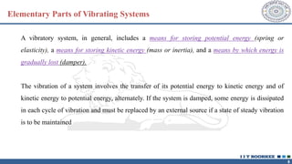
Elementary Parts ofVibrating Systems
A vibratory system, in general, includes a means for storing potential energy (spring or
elasticity), a means for storing kinetic energy (mass or inertia), and a means by which energy is
gradually lost (damper).
The vibration of a system involves the transfer of its potential energy to kinetic energy and of
kinetic energy to potential energy, alternately. If the system is damped, some energy is dissipated
in each cycle of vibration and must be replaced by an external source if a state of steady vibration
is to be maintained
9.
9
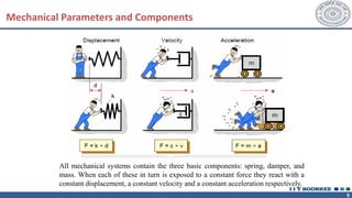
Mechanical Parameters andComponents
All mechanical systems contain the three basic components: spring, damper, and
mass. When each of these in turn is exposed to a constant force they react with a
constant displacement, a constant velocity and a constant acceleration respectively.
10.
10
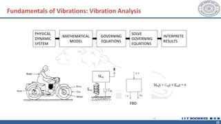
Fundamentals of Vibrations:Vibration Analysis
FBD
PHYSICAL
DYNAMIC
SYSTEM
MATHEMATICAL
MODEL
GOVERNING
EQUATIONS
SOLVE
GOVERNING
EQUATIONS
INTERPRETE
RESULTS
10
11.
11
Fundamentals of Vibrations
11
Modelingof the systems
Single degree of freedom (DOF)
Two DOF
Multi DOF
Free Damped
Forced
Or a combination of these modes
Continuous system
Each system can be under
Undamped
12.
12
✓ The studyof vibrations focuses on the oscillatory motion of elastic bodies and the forces acting on them.
✓ Anybody with mass and elasticity has the potential to vibrate.
✓ Engineering machines and structures commonly experience some level of vibration, making it essential to
consider their oscillatory behavior in the design process.
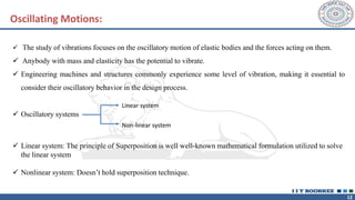
✓ Oscillatory systems
Linear system
Non-linear system
✓ Linear system: The principle of Superposition is well well-known mathematical formulation utilized to solve
the linear system
✓ Nonlinear system: Doesn’t hold superposition technique.
Oscillating Motions:
13.
13
✓ Periodic Motion– This motion repeats at equal intervals of time T.
✓ Period of Oscillatory – The time taken for one repetition is called a period.
✓ Frequency - It is defined reciprocal of time period, f =
1
𝑇
The condition of the periodic motion is
𝑥 𝑡 + 𝑇 = 𝑥 𝑡 where motion is designated by time function x(t).
✓ Harmonic motion : The simplest type of periodic motion is harmonic motion, It can be
represented as:
𝑥 = 𝐴 sin 2𝜋
𝑡
𝑇
where A is the amplitude of motion, t is the time instant and T is the period of motion.
Basic Terminology
14.
14
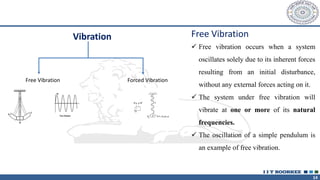
Vibration
Free Vibration ForcedVibration
Free Vibration
✓ Free vibration occurs when a system
oscillates solely due to its inherent forces
resulting from an initial disturbance,
without any external forces acting on it.
✓ The system under free vibration will
vibrate at one or more of its natural
frequencies.
✓ The oscillation of a simple pendulum is
an example of free vibration.
15.
15
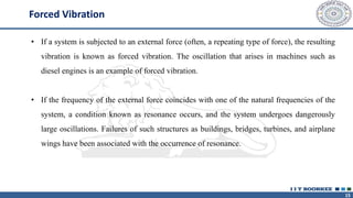
Forced Vibration
• Ifa system is subjected to an external force (often, a repeating type of force), the resulting
vibration is known as forced vibration. The oscillation that arises in machines such as
diesel engines is an example of forced vibration.
• If the frequency of the external force coincides with one of the natural frequencies of the
system, a condition known as resonance occurs, and the system undergoes dangerously
large oscillations. Failures of such structures as buildings, bridges, turbines, and airplane
wings have been associated with the occurrence of resonance.
16.
16
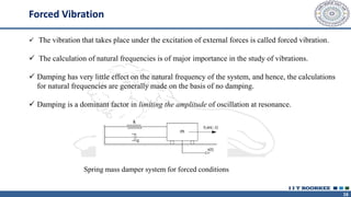
✓ The vibrationthat takes place under the excitation of external forces is called forced vibration.
✓ The calculation of natural frequencies is of major importance in the study of vibrations.
✓ Damping has very little effect on the natural frequency of the system, and hence, the calculations
for natural frequencies are generally made on the basis of no damping.
✓ Damping is a dominant factor in limiting the amplitude of oscillation at resonance.
Spring mass damper system for forced conditions
Forced Vibration
17.
17
Undamped and DampedVibration
• If no energy is lost or dissipated in friction or other resistance during oscillation, the vibration is
known as undamped vibration.
• If any energy is lost in this way, however, it is called damped vibration.
• In many physical systems, the amount of damping is so small that it can be disregarded for most
engineering purposes.
• However, consideration of damping becomes extremely important in analyzing vibratory systems
near resonance
18.
18
Linear and NonlinearVibration
• If all the basic components of a vibratory system the spring, the mass, and the damper behave linearly, the
resulting vibration is known as linear vibration.
• If, however, any of the basic components behave nonlinearly, the vibration is called nonlinear vibration.
• The differential equations that govern the behavior of linear and nonlinear vibratory systems are linear and
nonlinear, respectively.
• If the vibration is linear, the principle of superposition holds, and the mathematical techniques of analysis are
well developed.
• For nonlinear vibration, the superposition principle is not valid, and techniques of analysis are less well known.
• Since all vibratory systems tend to behave nonlinearly with increasing amplitude of oscillation, a knowledge of
nonlinear vibration is desirable in dealing with practical vibratory systems.
19.
19
Deterministic and RandomVibration
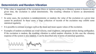
• If the value or magnitude of the excitation (force or motion) acting on a vibratory system is known at any
given time, the excitation is called deterministic. The resulting vibration is known as deterministic
vibration.
• In some cases, the excitation is nondeterministic or random; the value of the excitation at a given time
cannot be predicted. In these cases, a large collection of records of the excitation may exhibit some
statistical regularity.
• It is possible to estimate averages such as the mean and mean square values of the excitation.
• Examples of random excitations are wind velocity, road roughness, and ground motion during earthquakes.
If the excitation is random, the resulting vibration is called random vibration. In this case the vibratory
response of the system is also random; it can be described only in terms of statistical quantities.
Deterministic and Random Excitations
20.
20
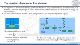
✓ The equationsof motion of a vibrating system can be derived using several methods. The applications of D
Alembert s principle, the principle of virtual displacements, and the principle of conservation of energy are
considered here.
✓ The basic vibration model includes a mass, spring (stiffness), and damper as depicted in Figures.
𝑚 ሷ
𝑥 = 𝐹
Newton's second law, we have
Equation of motion of the system
𝑚 ሷ
𝑥 = mg-k ∆ + 𝑥
𝑚 ሷ
𝑥 + kx = 0
We have k∆ = 𝑚𝑔 (i.e. spring force due to static
deflection is equal to the weight of the suspended mass)
The equation of motion for free vibration
21.
21
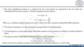
✓ The staticequilibrium position as a reference for the x-axis datum (as mentioned in the last slide) has
eliminated the force due to gravity. Therefore equation can be written as
ሷ
𝑥 + 𝜔𝑛
2𝑥 = 0
ሷ
𝑥 = −𝜔𝑛
2𝑥, 𝜔𝑛 =
𝑘
𝑚
Where 𝜔𝑛 is termed as natural frequency (in rad/𝑠2). Hence the above equation satisfied the SHM conditions.
✓ The motion is harmonic (i.e. the acceleration is proportional to the displacement).
✓ It is homogeneous, second order, linear differential equation (in the solution two arbitrary constants should be
there).
✓ The general solution of the above-mentioned equation can be written as
𝑥 = 𝐴 sin 𝜔𝑛𝑡 + 𝐵 cos 𝜔𝑛𝑡
ሶ
𝑥 = 𝐴𝜔𝑛 cos 𝜔𝑛𝑡 − 𝐵𝜔𝑛 sin 𝜔𝑛𝑡
Where A & B are the arbitrary constant, which depends on the initial conditions i.e. x(0) & ሶ
𝑥(0).
22.
22
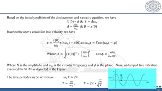
Based on theinitial condition of the displacement and velocity equation, we have
X (0) = B & ሶ
𝑥 = 𝐴𝜔𝑛
𝐴 =
ሶ
𝑥(0)
𝜔𝑛
& 𝐵 = 𝑥(0)
Inserted the above condition into velocity, we have
𝑥 =
ሶ
𝑥(0)
𝜔𝑛
𝑠𝑖𝑛𝜔𝑛𝑡 + 𝑥 0 𝑐𝑜𝑠𝜔𝑛𝑡 = 𝑋𝑐𝑜𝑠(𝜔𝑛𝑡 − 𝜙)
Where, X = 𝑥(0) 2 +
ሶ
𝑥(0)
𝜔𝑛
2
𝑡𝑎𝑛𝜙 =
ሶ
𝑥(0)
𝜔𝑛𝑥(0)
Where X is the amplitude and 𝜔𝑛 is the circular frequency and 𝜙 is the phase. Now, undamped free vibration
executed the SHM as depicted in the Figure.
The time periods can be written as 𝜔𝑛𝑇 = 2𝜋
𝑇 =
2𝜋
𝜔𝑛
, 𝑇 = 2𝜋 ∗
𝑚
𝑘
23.
23
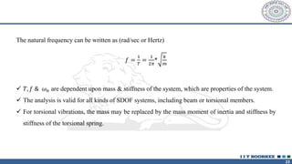
The natural frequencycan be written as (rad/sec or Hertz)
𝑓 =
1
𝑇
=
1
2𝜋
*
𝑘
𝑚
✓ 𝑇, 𝑓 & 𝜔𝑛 are dependent upon mass & stiffness of the system, which are properties of the system.
✓ The analysis is valid for all kinds of SDOF systems, including beam or torsional members.
✓ For torsional vibrations, the mass may be replaced by the mass moment of inertia and stiffness by
stiffness of the torsional spring.
24.
24
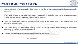
• A systemis said to be conservative if no energy is lost due to friction or energy-dissipating nonelastic
members.
• If no work is done on a conservative system by external forces (other than gravity or other potential
forces), then the total energy of the system remains constant.
• Since the energy of a vibrating system is partly potential and partly kinetic, the sum of these two
energies remains constant.
• The kinetic energy T is stored in the mass by virtue of its velocity, and the potential energy U is stored in
the spring by virtue of its elastic deformation.
• Thus the principle of conservation of energy can be expressed as:
Principle of Conservation of Energy
T + U = constant
25.
25
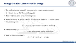
✓ The totalmechanical energy (E) in a conservative system remains constant:
✓ E = Kinetic Energy (T) + Potential Energy (U)
✓ dE/dt = 0 (No external forces performing work)
✓ This principle can be applied to derive the equation of motion for a vibrating system.
✓ Kinetic Energy (T):
T = (1/2) mẋ² (depends on the velocity of the mass)
✓ Potential Energy (U):
U = (1/2) kx² (stored elastic energy in the spring)
✓ Total Mechanical Energy (E)
E = T + U = (1/2) mẋ² + (1/2) kx²
Energy Method: Conservation of Energy
26.
26
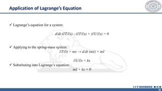
✓ Lagrange’s equationfor a system:
d/dt (∂T/∂ẋ) - (∂T/∂x) + (∂U/∂x) = 0
✓ Applying to the spring-mass system:
∂T/∂ẋ = mẋ → d/dt (mẋ) = mẍ
∂U/∂x = kx
✓ Substituting into Lagrange’s equation:
mẍ + kx = 0
Application of Lagrange’s Equation
27.
27
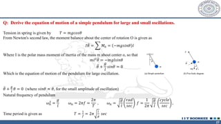
Q: Derive theequation of motion of a simple pendulum for large and small oscillations.
Tension in spring is given by 𝑇 = 𝑚𝑔𝑐𝑜𝑠𝜃
From Newton's second law, the moment balance about the center of rotation O is given as
𝐼 ሷ
𝜃 = 𝑀0 = −𝑚𝑔𝑠𝑖𝑛𝜃 𝑙
Where I is the polar mass moment of inertia of the mass m about center o, so that
𝑚𝑙2 ሷ
𝜃 = −𝑚𝑔𝑙𝑠𝑖𝑛𝜃
ሷ
𝜃 +
𝑔
𝑙
𝑠𝑖𝑛𝜃 = 0
Which is the equation of motion of the pendulum for large oscillation.
ሷ
𝜃 +
𝑔
𝑙
𝜃 = 0 (where 𝑠𝑖𝑛𝜃 ≈ 𝜃, for the small amplitude of oscillation)
Natural frequency of pendulum
𝜔𝑛
2 =
𝑔
𝑙
𝜔𝑛 = 2𝜋𝑓 =
2𝜋
𝑇
, 𝜔𝑛 =
𝑔
𝑙
𝑟𝑎𝑑
𝑠𝑒𝑐
𝑓 =
1
2𝜋
𝑔
𝑙
𝑐𝑦𝑐𝑙𝑒
𝑠𝑒𝑐
,
Time period is given as 𝑇 =
1
𝑓
= 2𝜋
𝑙
𝑔
𝑠𝑒𝑐
28.
28
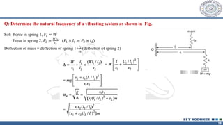
Q: Determine thenatural frequency of a vibrating system as shown in Fig.
Sol: Force in spring 1, 𝐹1 = 𝑊
Force in spring 2, 𝐹2 =
𝑊𝑙1
𝑙2
(𝐹1 × 𝑙1 = 𝐹2 × 𝑙2)
Deflection of mass = deflection of spring 1+
𝑙1
𝑙2
(deflection of spring 2)
29.
29
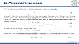
Free Vibration withViscous Damping
The viscous damping force F is proportional to the velocity ሶ
𝑥or v and can be expressed as
where c is the damping constant or coefficient of viscous damping and the negative sign indicates that the damping
force is opposite to the direction of velocity. A single-degree-of-freedom system with a viscous damper is shown in
Fig. (a). If x is measured from the equilibrium position of the mass m, the application of Newton’s law yields the
equation of motion:
……(2)
….(3)
To solve Eq. (2.59), we assume a solution in the form
where C and s are undetermined constants. Inserting this function into Eq. (2.59) leads to the characteristic equation
……(4)
……(1)
30.
30
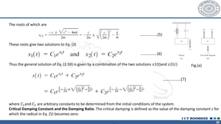
The roots ofwhich are
…….……..…(5)
These roots give two solutions to Eq. (3)
Thus the general solution of Eq. (2.59) is given by a combination of the two solutions 𝑥1(t)and 𝑥2 𝑡
………… ………………(7)
where 𝐶1and 𝐶2 are arbitrary constants to be determined from the initial conditions of the system.
Critical Damping Constant and the Damping Ratio. The critical damping is defined as the value of the damping constant c for
which the radical in Eq. (5) becomes zero:
………..…...(6)
Fig.(a)
31.
31
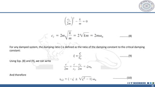
For any dampedsystem, the damping ratio ζ is defined as the ratio of the damping constant to the critical damping
constant:
Using Eqs. (8) and (9), we can write
And therefore
………….(8)
………….(9)
𝜉 =
𝐶
𝐶𝑐
…………………(10)
32.
32
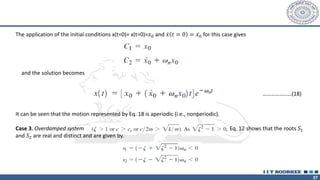
Thus the solution,Eq. (7) can be written as
The nature of the roots and hence the behavior of the solution, Eq. (11), depends upon the magnitude of damping. It can
be seen that the case leads to the undamped vibrations discussed in Section 2.2. Hence we assume that and consider the
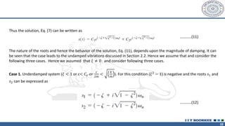
following three cases. Hence we assumed that 𝜉 ≠ 0 and consider following three cases.
Case 1. Underdamped system (𝜉 < 1 or c< 𝐶𝑐 𝑜𝑟
𝑐
2𝑚
<
𝑘
𝑚
). For this condition (𝜉2
− 1) is negative and the roots 𝑠1 and
𝑠2 can be expressed as
…………(11)
…………(12)
34
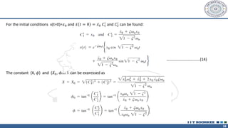
For the initialconditions x(t=0)=𝑥0 and ሶ
𝑥 𝑡 = 0 = ሶ
𝑥0 𝐶1
′
and 𝐶2
′
can be found:
The constant (X, 𝜙) and (𝑋0, 𝜙 0 ) can be expressed as
…………………………….(14)
35.
35
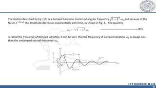
The motion describedby Eq. (13) is a damped harmonic motion of angular frequency 1 − 𝜉2 𝜔𝑛,but because of the
factor 𝑒−𝜉𝜔𝑛𝑡
the amplitude decreases exponentially with time, as shown in Fig 2. . The quantity
is called the frequency of damped vibration. It can be seen that the frequency of damped vibration 𝜔𝑑 is always less
than the undamped natural frequency 𝜔𝑛
……………………………………..…………(15)
36.
36
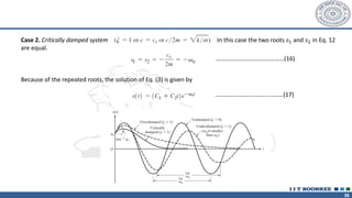
Case 2. Criticallydamped system In this case the two roots 𝑠1 and 𝑠2 in Eq. 12
are equal.
Because of the repeated roots, the solution of Eq. (3) is given by
………………………………………(16)
………………………………………(17)
37.
37
The application ofthe initial conditions x(t=0)= x(t=0)=𝑥0 and ሶ
𝑥 𝑡 = 0 = ሶ
𝑥0 for this case gives
and the solution becomes
It can be seen that the motion represented by Eq. 18 is aperiodic (i.e., nonperiodic).
Case 3. Overdamped system Eq. 12 shows that the roots 𝑆1
and 𝑆2 are real and distinct and are given by.
…………………(18)
38.
38
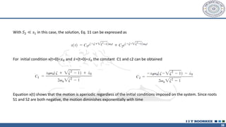
With 𝑆2 ≪𝑠1 in this case, the solution, Eq. 11 can be expressed as
For initial condition x(t=0)=𝑥0 and ሶ
𝑥=(t=0)= ሶ
𝑥0 the constant C1 and c2 can be obtained
Equation x(t) shows that the motion is aperiodic regardless of the initial conditions imposed on the system. Since roots
S1 and S2 are both negative, the motion diminishes exponentially with time
39.
39
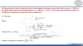
Q: Determine thetime in which the mass in the damped vibrating system would settle down to 1/50th of
its initial deflection for the following data: m = 200 kg 𝜉 = 0.22 s = 40 N/mm. Also, find the number of
oscillations completed to reach this value of deflection.
Sol: We have,
𝑋0
𝑋𝑁
= 𝑒𝜉𝜔𝑛𝑁𝑇𝑑
Where
𝜔𝑛 =
𝑠
𝑚
=
40 × 103
200
=
14.14𝑟𝑎𝑑
𝑠
50 = 𝑒0.22×14.1𝑁𝑇𝑑
Total time 𝑁𝑇𝑑 = 1.26𝑠𝑒𝑐
𝑇𝑑 = 2𝜋/ 1 − 𝜉2𝜔𝑛
=
2𝜋
1 − 0.22 2
× 14.14 = 0.455 𝑠𝑒𝑐
Number of oscillations completed =
1.26
0.455
= 2.76
40.
40
Q: A machinemounted on springs and fitted with a dashpot has a mass of 60 kg. There are three springs,
each of stiffness 12N/mm. The amplitude of vibration reduces from 45 to 8 mm in two complete oscillations.
Assuming that the damping force varies as the velocity determines the
(i) Damping coefficient
(ii) Ratio of frequencies of damped and undamped vibrations
(iii) Periodic time of damped vibrations
Sol: m=60 kg, stiffness of each spring = 12N/mm, Combined stiffness, s=12×3=36N/mm
(i) 𝜔𝑛 =
𝑠
𝑚
= 36 ×
103
60
= 24.49
𝑟𝑎𝑑
𝑠
𝑖
𝑋
𝑋2
=
𝑋0
𝑋1
×
𝑋1
𝑋2
=
𝑋0
𝑋1
2
𝑋0
𝑋1
=
𝑋0
𝑋2
1/2
=
45
8
1
2
= 2.37
2𝜋𝜉
1 − 𝜉2
= ln 2.37 = 0.864, 1 − 𝜉2
= 52.88𝜉2
𝑜𝑟, 𝜉2
= 0.0185 𝑜𝑟, 𝜉 = 0.136
𝑐 = 2𝑚𝜔𝑛𝜉 = 2 × 60 ×24.49×0.136=400N/m/s=0.4N/mm/s
42
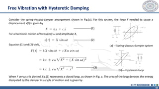
Free Vibration withHysteretic Damping
Consider the spring-viscous-damper arrangement shown in Fig.(a). For this system, the force F needed to cause a
displacement x(t) is given by
For a harmonic motion of frequency 𝜔 and amplitude X,
Equation (1) and (2) yield,
When F versus x is plotted, Eq.(3) represents a closed loop, as shown in Fig. a. The area of the loop denotes the energy
dissipated by the damper in a cycle of motion and is given by
-------------------(1)
-------------------(2)
-------------------(3)
(a) ---Spring-viscous-damper system
(b)--- Hysteresis loop.
43.
43
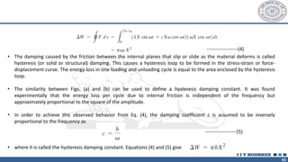
-------------------(4)
• The dampingcaused by the friction between the internal planes that slip or slide as the material deforms is called
hysteresis (or solid or structural) damping. This causes a hysteresis loop to be formed in the stress-strain or force-
displacement curve. The energy loss in one loading and unloading cycle is equal to the area enclosed by the hysteresis
loop.
• The similarity between Figs. (a) and (b) can be used to define a hysteresis damping constant. It was found
experimentally that the energy loss per cycle due to internal friction is independent of the frequency but
approximately proportional to the square of the amplitude.
• In order to achieve this observed behavior from Eq. (4), the damping coefficient c is assumed to be inversely
proportional to the frequency as
• where h is called the hysteresis damping constant. Equations (4) and (5) give
-------------------(5)
44.
44
Forced Vibration
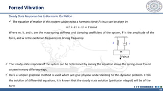
Steady StateResponse due to Harmonic Oscillation :
✓ The equation of motion of this system subjected to a harmonic force 𝐹𝑠𝑖𝑛𝜔𝑡 can be given by
𝑚 ሷ
𝑥 + 𝑘𝑥 + 𝑐 ሶ
𝑥 = 𝐹𝑠𝑖𝑛𝜔𝑡
Where m, k, and c are the mass-spring stiffness and damping coefficient of the system, F is the amplitude of the
force, and w is the excitation frequency or driving frequency.
✓ The steady-state response of the system can be determined by solving the equation above the spring-mass forced
system in many different ways.
✓ Here a simpler graphical method is used which will give physical understanding to this dynamic problem. From
the solution of differential equations, it is known that the steady state solution (particular integral) will be of the
form
45.
45
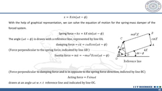
𝑥 = 𝑋𝑠𝑖𝑛(𝜔𝑡− 𝜙)
With the help of graphical representation, we can solve the equation of motion for the spring-mass damper of the
forced system.
Spring force = 𝑘𝑥 = 𝑘𝑋 sin 𝜔𝑡 − 𝜙
The angle (𝜔𝑡 − 𝜙) is drawn with a reference line, represented by line 0A.
damping force = 𝑐 ሶ
𝑥 = 𝑐𝜔𝑋𝑐𝑜𝑠 𝜔𝑡 − 𝜙
Force perpendicular to the spring force, indicated by line AB
Inertia force = m ሶ
𝑥 = −𝑚𝜔2𝑋𝑐𝑜𝑠 𝜔𝑡 − 𝜙
(Force perpendicular to damping force and is in opposite to the spring force direction, indicted by line BC)
Acting force = 𝐹𝑠𝑖𝑛𝜔𝑡
drawn at an angle 𝜔𝑡 𝑤. 𝑟. 𝑡 reference line and indicated by line OC.
46.
46
https://www.youtube.com/watch?v=XggxeuFDaDU
✓ Resonance occurswhen the forcing frequency (ω) matches the natural frequency (𝜔𝑛):
✓ Leads to large amplitude oscillations.
✓ Can cause structural failure if not controlled.
Examples:
✓ Tacoma Narrows Bridge collapse (https://www.youtube.com/watch?v=XggxeuFDaDU)
✓ Vibrations in aircraft and rotating machinery.
47.
47
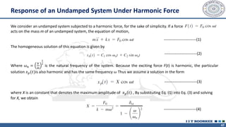
Response of anUndamped System Under Harmonic Force
We consider an undamped system subjected to a harmonic force, for the sake of simplicity. If a force
acts on the mass m of an undamped system, the equation of motion,
The homogeneous solution of this equation is given by
Where 𝜔𝑛 =
𝑘
𝑚
1
2
is the natural frequency of the system. Because the exciting force F(t) is harmonic, the particular
solution 𝑥𝑝(𝑡)is also harmonic and has the same frequency 𝜔 Thus we assume a solution in the form
where X is an constant that denotes the maximum amplitude of 𝑥𝑝 𝑡 , By substituting Eq. (1) into Eq. (3) and solving
for X, we obtain
-------------------------(1)
-------------------------(2)
-------------------------(3)
-------------------------(4)
48.
48
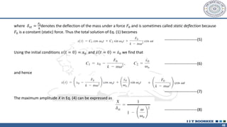
where 𝛿𝑠𝑡 =
𝐹0
𝑘
denotesthe deflection of the mass under a force 𝐹0 and is sometimes called static deflection because
𝐹0 is a constant (static) force. Thus the total solution of Eq. (1) becomes
Using the initial conditions 𝑥 𝑡 = 0 = 𝑥0 and ሶ
𝑥 𝑡 = 0 = ሶ
𝑥0 we find that
and hence
The maximum amplitude X in Eq. (4) can be expressed as
-------------------------(5)
-------------------------(6)
-------------------------(7)
-------------------------(8)
49.
49
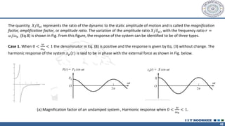
The quantity 𝑋/𝛿𝑠𝑡represents the ratio of the dynamic to the static amplitude of motion and is called the magnification
factor, amplification factor, or amplitude ratio. The variation of the amplitude ratio 𝑋/𝛿𝑠𝑡, with the frequency ratio 𝑟 =
𝜔/𝜔𝑛 (Eq.8) is shown in Fig. From this figure, the response of the system can be identified to be of three types.
Case 1. When 0 <
𝜔
𝜔𝑛
< 1 the denominator in Eq. (8) is positive and the response is given by Eq. (3) without change. The
harmonic response of the system 𝑥𝑝(𝑡) is said to be in phase with the external force as shown in Fig. below.
(a) Magnification factor of an undamped system , Harmonic response when 0 <
𝜔
𝜔𝑛
< 1.
50.
50
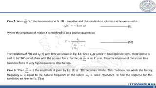
Case 2. When
𝜔
𝜔𝑛
>1the denominator in Eq. (8) is negative, and the steady-state solution can be expressed as
Where the amplitude of motion X is redefined to be a positive quantity as
The variations of F(t) and 𝑥𝑝(𝑡) with time are shown in Fig. 3.5. Since 𝑥𝑝(𝑡) and F(t) have opposite signs, the response is
said to be 180° out of phase with the external force. Further, as
𝜔
𝜔𝑛
→ ∞, 𝑋 → ∞. Thus the response of the system to a
harmonic force of very high frequency is close to zero.
Case 3. When
𝜔
𝜔𝑛
= 1 the amplitude X given by Eq. (8) or (10) becomes infinite. This condition, for which the forcing
frequency 𝜔 is equal to the natural frequency of the system 𝜔𝑛 is called resonance. To find the response for this
condition, we rewrite Eq. (7) as
-------------------------------(9)
-------------------------------(10)
51.
51
Since the lastterm of this equation takes an indefinite form for 𝜔 = 𝜔𝑛 we apply L Hospital s rule [1] to evaluate the limit
of this term:
Thus the response of the system at resonance becomes
-----------------------(11)
-----------------------(12)
-----------------------(13)
52.
52
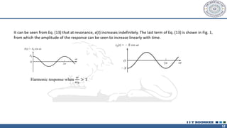
It can beseen from Eq. (13) that at resonance, x(t) increases indefinitely. The last term of Eq. (13) is shown in Fig. 1,
from which the amplitude of the response can be seen to increase linearly with time.
Harmonic response when
𝜔
𝜔𝑛
> 1
53.
53
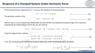
Response of aDamped System Under Harmonic Force
If the forcing function is given by 𝐹 𝑡 = 𝐹𝑛𝑐𝑜𝑠𝜔𝑡 the equation of motion becomes
The particular solution of Eq.
where X and 𝜙 are constants to be determined. X and 𝜙 denote the amplitude and phase angle of the response,
respectively, By substituting Eq. (2) into Eq. (1), we arrive at
Using the trigonometric relations
In Eq. (3) and equating the coefficients of and on both sides of the resulting equation, we obtain
-----------------------------------(1)
-----------------------------------(2)
-----------------------------------(3)
-----------------------------------(4)
-----------------------------------(5)
54.
54
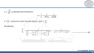
𝜔 =
𝑘
𝑚
=undamped naturalfrequency
𝜉 =
𝑐
𝑐𝑐
=
𝑐
2𝑚𝜔𝑛
=
𝑐
2 𝑚𝑘
;
𝛿 =
𝐹0
𝑘
= 𝑑𝑒𝑓𝑙𝑒𝑐𝑡𝑖𝑜𝑛 𝑢𝑛𝑑𝑒𝑟 the static force 𝐹0 and 𝑟 =
𝜔
𝜔𝑛
We obtained,
------------------------------(6)
55.
55
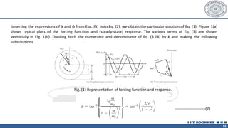
Inserting the expressionsof X and 𝜙 from Eqs. (5) into Eq. (2), we obtain the particular solution of Eq. (1). Figure 1(a)
shows typical plots of the forcing function and (steady-state) response. The various terms of Eq. (3) are shown
vectorially in Fig. 1(b). Dividing both the numerator and denominator of Eq. (3.28) by k and making the following
substitutions.
Fig. (1) Representation of forcing function and response.
-----------------------(7)
56.
56
The quantity 𝑀=
𝑋
𝛿𝑠𝑡
is called the magnification factor, amplification factor, or amplitude ratio. The variations 𝑋/𝛿𝑠𝑡 of
and 𝜙 with the frequency ratio r and the damping ratio are shown in Fig. 2.
The following characteristics of the magnification factor (M) can be noted from Eq. (9) and Fig. 2(a):
✓ For an undamped system (𝜉 = 0) Eq. (9) reduces to the ratio of the dynamic to the static amplitude of motion, and
M→ ∞ as r→ 1.
✓ Any amount of damping (𝜉 > 0) reduces the magnification factor (M) for all values of the forcing frequency.
✓ For any specified value of r, a higher value of damping reduces the value of M.
✓ In the degenerate case of a constant force (when r=0 ), the value of M=1
✓ The reduction in M in the presence of damping is very significant at or near resonance.
✓ The amplitude of forced vibration becomes smaller with increasing values of the forcing
✓ Frequency (𝑖. 𝑒, 𝑀 → 0 𝑎𝑠 𝑟 → ∞)
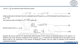
58
For 0<𝜉 <
1
2
themaximum value of M occurs when
which can be seen to be lower than the undamped natural frequency 𝜔𝑛 and the damped natural frequency 𝜔𝑑 =
𝜔 1 − 2𝜉2
The maximum value of X (When r= 1 − 2𝜉2) is given by
𝑋
𝛿𝑠𝑡 𝑚𝑎𝑥
= 1/2𝜉 1 − 𝜉2
And the value of X at 𝜔 = 𝜔𝑛 by
𝑋
𝛿𝑠𝑡 𝜔=𝜔𝑛
=
1
2𝜉
Equation (9) can be used for the experimental determination of the measure of damping present in the system. In a
vibration test, if the maximum amplitude of the response 𝑥𝑚𝑎𝑥 is measured, the damping ratio of the system can be
found using Eq. (9). Conversely, if the amount of damping is known, one can make an estimate of the maximum
amplitude of vibration.
--------------------------------(8)
--------------------------------(9)
--------------------------------(10)
59.
59
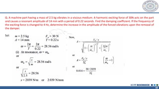
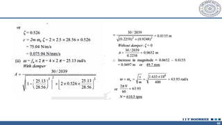
Q. A machinepart having a mass of 2.5 kg vibrates in a viscous medium. A harmonic exciting force of 30N acts on the part
and causes a resonant amplitude of 14 mm with a period of 0.22 seconds. Find the damping coefficient. lf the frequency of
the exciting force is changed to 4 Hz, determine the increase in the amplitude of the forced vibrations upon the removal of
the damper.
Sol:
61
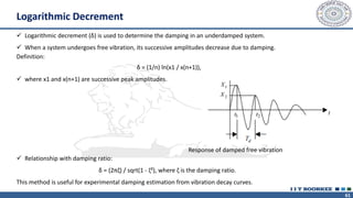
✓ Logarithmic decrement(δ) is used to determine the damping in an underdamped system.
✓ When a system undergoes free vibration, its successive amplitudes decrease due to damping.
Definition:
δ = (1/n) ln(x1 / x(n+1)),
✓ where x1 and x(n+1) are successive peak amplitudes.
✓ Relationship with damping ratio:
δ = (2πζ) / sqrt(1 - ζ²), where ζ is the damping ratio.
This method is useful for experimental damping estimation from vibration decay curves.
Response of damped free vibration
Logarithmic Decrement
63
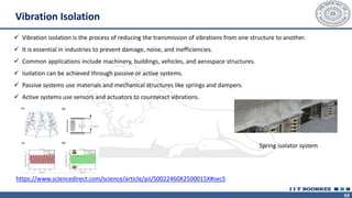
Vibration Isolation
✓ Vibrationisolation is the process of reducing the transmission of vibrations from one structure to another.
✓ It is essential in industries to prevent damage, noise, and inefficiencies.
✓ Common applications include machinery, buildings, vehicles, and aerospace structures.
✓ Isolation can be achieved through passive or active systems.
✓ Passive systems use materials and mechanical structures like springs and dampers.
✓ Active systems use sensors and actuators to counteract vibrations.
Spring isolator system
https://www.sciencedirect.com/science/article/pii/S0022460X2500015X#sec5
64.
64
✓ To designa shock absorber, for example, it is necessary to specify its stiffness and damping coefficient damping
coefficients.
✓ To find these values, it is important to determine certain design parameters from the transmissibility function.
✓ It is a crucial parameter in vibration control.
✓ Transmissibility (𝑇) is a measure of how vibrations or forces are transmitted from one system to another.
✓ It is typically defined in the context of vibration isolation and dynamics as the ratio of the output response
(displacement, velocity, or acceleration) to the input excitation.
✓ Mathematical expression for Single-degree-of-freedom (SDOF) system subjected to harmonic excitation
𝑇 =
𝑂𝑢𝑡𝑝𝑢𝑡 𝑒𝑥𝑐𝑖𝑡𝑎𝑡𝑖𝑜𝑛
𝐼𝑛𝑝𝑢𝑡 𝑒𝑥𝑐𝑖𝑡𝑎𝑡𝑖𝑜𝑛
Transmissibility
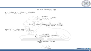
65.
65
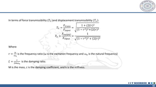
In terms offorce transmissibility (𝑇𝐹)and displacement transmissibility (𝑇𝑥):
𝑇𝐹 =
𝐹𝑡𝑟𝑎𝑛𝑠
𝐹𝑖𝑛𝑝𝑢𝑡
=
1 + (2𝜉𝑟)2
(1 − 𝑟2)2+ 2𝜉𝑟 2
𝑇𝑥 =
𝑋𝑜𝑢𝑡𝑝𝑢𝑡
𝑋𝑖𝑛𝑝𝑢𝑡
=
1
1 − 𝑟2 2 + 2𝜉𝑟 2
Where
𝑟 =
𝜔
𝜔𝑛
is the frequency ratio (ω is the excitation frequency and 𝜔𝑛 is the natural frequency)
𝜉 =
𝑐
2𝑚𝜔𝑛
is the damping ratio.
M is the mass, c is the damping coefficient, and k is the stiffness.
66.
66
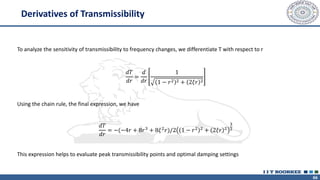
To analyze thesensitivity of transmissibility to frequency changes, we differentiate T with respect to r
𝑑𝑇
𝑑𝑟
=
𝑑
𝑑𝑟
1
1 − 𝑟2 2 + 2𝜉𝑟 2
Using the chain rule, the final expression, we have
𝑑𝑇
𝑑𝑟
= −(−4𝑟 + 8𝑟3
+ 8𝜉2
𝑟)/2 1 − 𝑟2 2
+ 2𝜉𝑟 2
3
2
This expression helps to evaluate peak transmissibility points and optimal damping settings
Derivatives of Transmissibility
67.
67
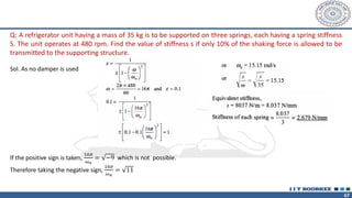
Q: A refrigeratorunit having a mass of 35 kg is to be supported on three springs, each having a spring stiffness
S. The unit operates at 480 rpm. Find the value of stiffness s if only 10% of the shaking force is allowed to be
transmitted to the supporting structure.
Sol. As no damper is used
If the positive sign is taken,
16𝜋
𝜔𝑛
= −9 which is not possible.
Therefore taking the negative sign,
16𝜋
𝜔𝑛
= 11
68.
68
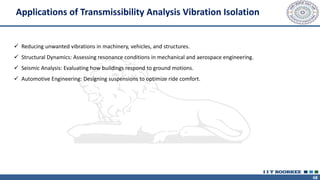
✓ Reducing unwantedvibrations in machinery, vehicles, and structures.
✓ Structural Dynamics: Assessing resonance conditions in mechanical and aerospace engineering.
✓ Seismic Analysis: Evaluating how buildings respond to ground motions.
✓ Automotive Engineering: Designing suspensions to optimize ride comfort.
Applications of Transmissibility Analysis Vibration Isolation


![51
Since the last term of this equation takes an indefinite form for 𝜔 = 𝜔𝑛 we apply L Hospital s rule [1] to evaluate the limit
of this term:
Thus the response of the system at resonance becomes
-----------------------(11)
-----------------------(12)
-----------------------(13)](https://image.slidesharecdn.com/mechanicalvibrationmic202-250614094156-0805a166/85/Mechanical-Vibration_MIC-202_iit-roorkee-pdf-51-320.jpg)