Downloaded 291 times
![At some intermediate point P′ on the path, the electrostatic force on a unit
positive charge is
𝑭
⃗⃗ =
𝟏
𝟒𝝅 ∈𝟎
𝑸
𝒓′𝟐
𝒓′
̂
where 𝒓′
̂ is the unit vector along OP′.
Work done against this force from r′ to r′ + dr’ is
𝒅𝒘 =
−𝟏
𝟒𝝅 ∈𝟎
𝑸𝒅𝒓′
𝒓′𝟐
The negative sign appears because for ∆r′ < 0, ∆W is positive .
Total work done (W) by the external force is obtained by integrating Eq. (2.6)
from r ′ = ∞ to r ′ = r,
𝑾 = ∫ 𝒅𝒘
𝒓
∞
𝑾 = ∫
−𝟏
𝟒𝝅 ∈𝟎
𝒓
∞
𝑸𝒅𝒓′
𝒓′𝟐
=
− 𝑸
𝟒𝝅∈𝟎
∫
𝟏
𝒓′𝟐
𝒓
∞
dr’
=
− 𝑸
𝟒𝝅∈𝟎
[
−𝟏
𝒓′
]
∞
𝒓
=
𝟏
𝟒𝝅∈𝟎
𝑸
𝒓
Therefore, the potential at P, V =
𝟏
𝟒𝝅∈𝟎
𝑸
𝒓
The potential difference between two points is independent of the path through
which it is displaced. But depends only on the initial and final positions.
Electric field is a conservative field, because the work done in moving a charge
from one point to another is independent of the path, but depends on ly on the
initial and final positions, ie the work done by the electrostatic force over a
closed path is zero.
All right copy reserved. No part of the material can be produced without prior permission](https://image.slidesharecdn.com/electrostatelectrostaticpotentialandcapacitance-240330110556-d9887647/75/ELECTROSTAT-ELECTROSTATIC-POTENTIAL-AND-CAPACITANCE-Class-12-Study-material-in-pdf-2-2048.jpg)
![For a short dipole
If we consider the case where r>>a then, ie,
𝑉 =
𝑝 𝑐𝑜𝑠𝜃
4𝜋𝑟2
Case 1. A point on the axial line.
For a point l on the axial line of the dipole, (𝜃 = 0)
Therefore, cos θ = cos 0 = 1
Substituting this in the above expression
𝑉 =
𝑝
4𝜋 ∈0 𝑟2
Case 2. A point on the equatorial line.
For a point l on the axial line of the dipole, (𝜃 = 90)
Therefore, cos θ = cos90 = 0
Substituting this in the above expression
V = 0
Potential at a point due to two charges
Consider two-point charges q1 and q2 kept in air at A and B respectively. The
electric potential at a point P which is at distances r1 and r2 respectively from A and B
respectively.
The potential at P due to the charge q1, V1 =
1
4𝜋∈0
𝑞1
𝑟1
The potential at P due to the charge q2, V2 =
1
4𝜋∈0
𝑞2
𝑟2
Therefore, the potential at P, V = V1+ V2 =
1
4𝜋∈0
𝑞1
𝑟1
+
1
4𝜋∈0
𝑞2
𝑟2
V =
1
4𝜋∈0
[
𝑞1
𝑟1
+
𝑞2
𝑟2
]
Therefore potential at appoint due to n charges V =
𝟏
𝟒𝝅∈𝟎
[
𝒒𝟏
𝒓𝟏
+
𝒒𝟐
𝒓𝟐
+ ⋯ +
𝒒𝒏
𝒓𝒏
]
All right copy reserved. No part of the material can be produced without prior permission](https://image.slidesharecdn.com/electrostatelectrostaticpotentialandcapacitance-240330110556-d9887647/75/ELECTROSTAT-ELECTROSTATIC-POTENTIAL-AND-CAPACITANCE-Class-12-Study-material-in-pdf-5-2048.jpg)
![ELECTRIC POTENTIAL ENERGY OF A SYSTEM OF CHRGES
(In the absence of external electric field)
Potential energy of a system of charges is defined as the work done in bringing
them from infinite separation to the present position.
Consider a system of 3 charges q1, q2 and q3 in air. let the position vector
charges are r1, r2 and r3 respectively. Let us consider that these charges are kept
initially at infinite separation. We can find the work done in bringing them from infinite
separation to the present position.
The work done to bring q1 from infinity to its present position is zero, because it
is moved in a charge free region.
W1= 0
The work done to bring q2 from infinity to its present position is
W2 = V1 X q2
=
1
4𝜋∈0
𝑞1𝑞2
𝑟12
The work done in bringing the charge q3 from infinity to ‘r3’ is
𝑊3 = q3 (𝑣1 + 𝑣2)
= q3 [
1
4𝜋𝜀0
[
𝑞1
𝑟13
+
𝑞2
𝑟23
]
=
1
4𝜋𝜀0
[
𝑞1𝑞3
𝑟13
+
𝑞2𝑞3
𝑟23
]
∴ Total energy of the system is
=
𝟏
𝟒𝝅𝜺𝟎
[
𝒒𝟏𝒒𝟐
𝒓𝟏𝟐
+
𝒒𝟏𝒒𝟑
𝒓𝟏𝟑
+
𝒒𝟐𝒒𝟑
𝒓𝟐𝟑
]
All right copy reserved. No part of the material can be produced without prior permission](https://image.slidesharecdn.com/electrostatelectrostaticpotentialandcapacitance-240330110556-d9887647/75/ELECTROSTAT-ELECTROSTATIC-POTENTIAL-AND-CAPACITANCE-Class-12-Study-material-in-pdf-7-2048.jpg)
![Potential energy of a dipole in an external field
dω = 𝜏d 𝜃 = p E Sin𝜃 d𝜃
The work done in rotating the dipole from an angle θ1to θ2 is given by
𝑊 = ∫
𝑝𝐸𝑠𝑖𝑛𝜃𝑑𝜃 = −𝑝𝐸[𝑠𝑐𝑜𝑠𝜃]𝜃2
𝜃1
𝜃2
𝜃1
= −𝑝𝐸(𝑐𝑜𝑠𝜃2 − 𝑐𝑜𝑠𝜃1)
W = p E (𝑐𝑜𝑠𝜃1 − 𝑐𝑜𝑠𝜃2)
The potential energy of the dipole at an angle θ with electric field can be obtained by
integrating the above equation from 𝜋
2
⁄ to 𝜃
i.e. 𝒰 = ∫ pESin𝜃d𝜃
𝜃
𝜋
2
⁄
= pE ∫ Sin𝜃d𝜃
𝜃
𝜋
2
⁄
= pE [-Cos 𝜃]𝜋
2
⁄
𝜃
= - pE [Cos 𝜃 – Cos𝜋
2
⁄ ]
= -pE (Cos 𝜃 - 0)
All right copy reserved. No part of the material can be produced without prior permission](https://image.slidesharecdn.com/electrostatelectrostaticpotentialandcapacitance-240330110556-d9887647/75/ELECTROSTAT-ELECTROSTATIC-POTENTIAL-AND-CAPACITANCE-Class-12-Study-material-in-pdf-9-2048.jpg)
![Energy stored in a capacitor
Let us consider a parallel plate capacitors of area A and separation of the plates
as ‘d’ so that the capacitance is
C =
𝜀0𝐴
𝑑
If a charge ‘q’ is given to the capacitor, its potential is ‘v’ so that
C =
𝑞
𝑣
or V =
𝑞
𝐶
Now the work done in giving an additional charge dq to it is
d𝜔 = Vdq
i.e. d𝜔 =
𝑞
𝑣
dq
Now the total work done in charge the capacitor from q=0 to q=Q is obtained by
integration as
𝜔 = ∫
𝑞
𝑣
dq
𝑄
0
=
1
𝐶
[
𝑞2
2
]0
𝑄
=
1
𝐶
𝑄2
2
=
𝑄2
2𝐶
This work done is stored in the capacitor as electro static potential energy in the
electric field between the plates.
𝑈 =
𝑄2
2𝐶
=
1
2
CV2
=
1
2
QV
All right copy reserved. No part of the material can be produced without prior permission](https://image.slidesharecdn.com/electrostatelectrostaticpotentialandcapacitance-240330110556-d9887647/75/ELECTROSTAT-ELECTROSTATIC-POTENTIAL-AND-CAPACITANCE-Class-12-Study-material-in-pdf-13-2048.jpg)
![If the Capacitors are connected in Series the same charge ‘Q’ will be reaching to
all the capacitors and the potential ‘V’ is divided into V1, V2 and V3 across C1, C2
and C3 respectively.
∴ V = V1+ V2 + V3 (1)
But, V1=
𝑄
𝐶1
, V2 =
𝑄
𝐶2
and V3 =
𝑄
𝐶3
∴ V =
𝑄
𝐶1
+
𝑄
𝐶2
+
𝑄
𝐶3
= Q [
1
𝐶1
+
1
𝐶2
+
1
𝐶3
] (2)
If these capacitors are replaced by an equivalent capacitance ‘Cs’ such that the
voltage ‘V’ and the charge ‘Q’ remains the same, then
V =
𝑄
𝐶𝑠
(3)
From Equation: (2) and (3)
𝑄
𝐶𝑠
= Q[
1
𝐶1
+
1
𝐶2
+
1
𝐶3
]
i.e.
1
𝐶𝑠
=
1
𝐶1
+
1
𝐶2
+
1
𝐶3
All right copy reserved. No part of the material can be produced without prior permission](https://image.slidesharecdn.com/electrostatelectrostaticpotentialandcapacitance-240330110556-d9887647/75/ELECTROSTAT-ELECTROSTATIC-POTENTIAL-AND-CAPACITANCE-Class-12-Study-material-in-pdf-15-2048.jpg)
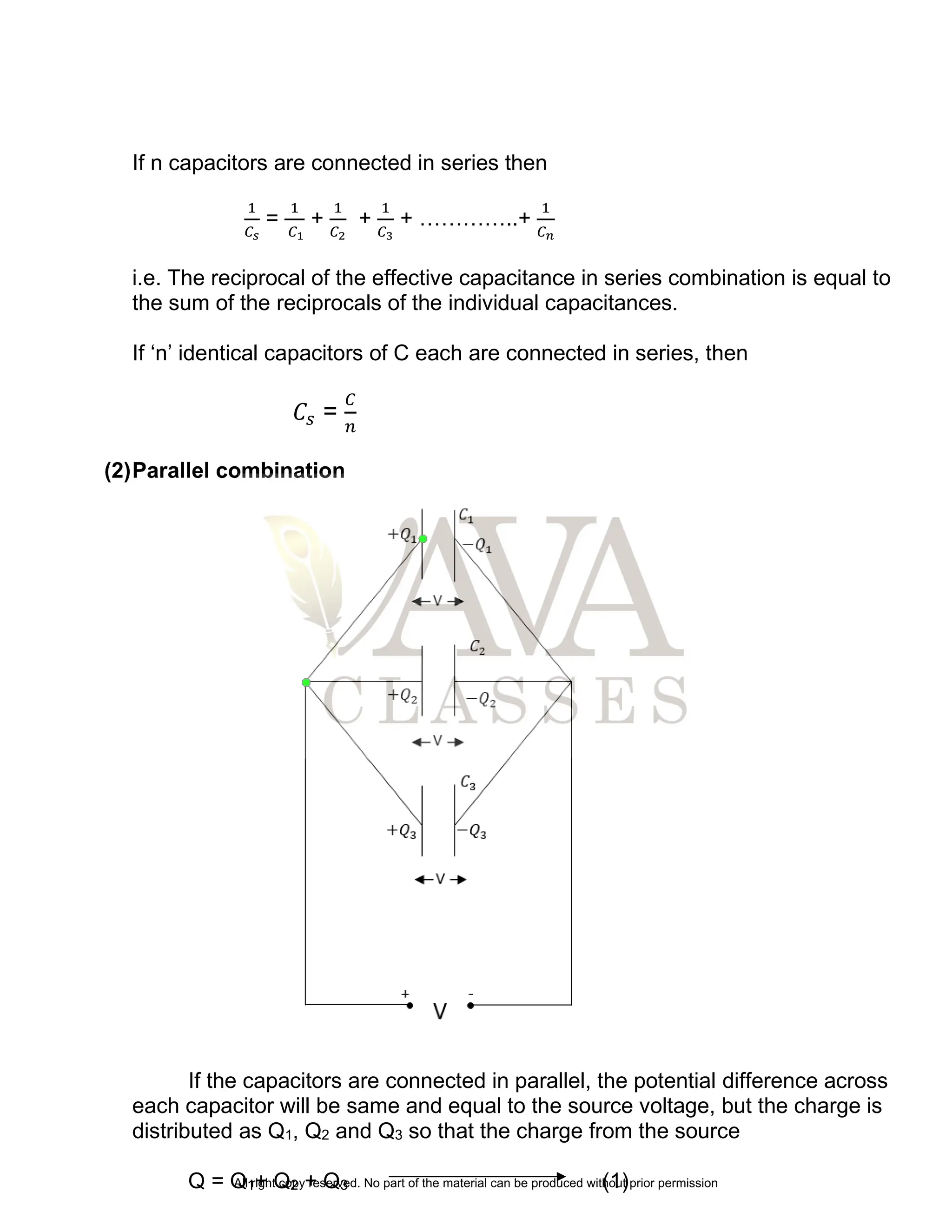
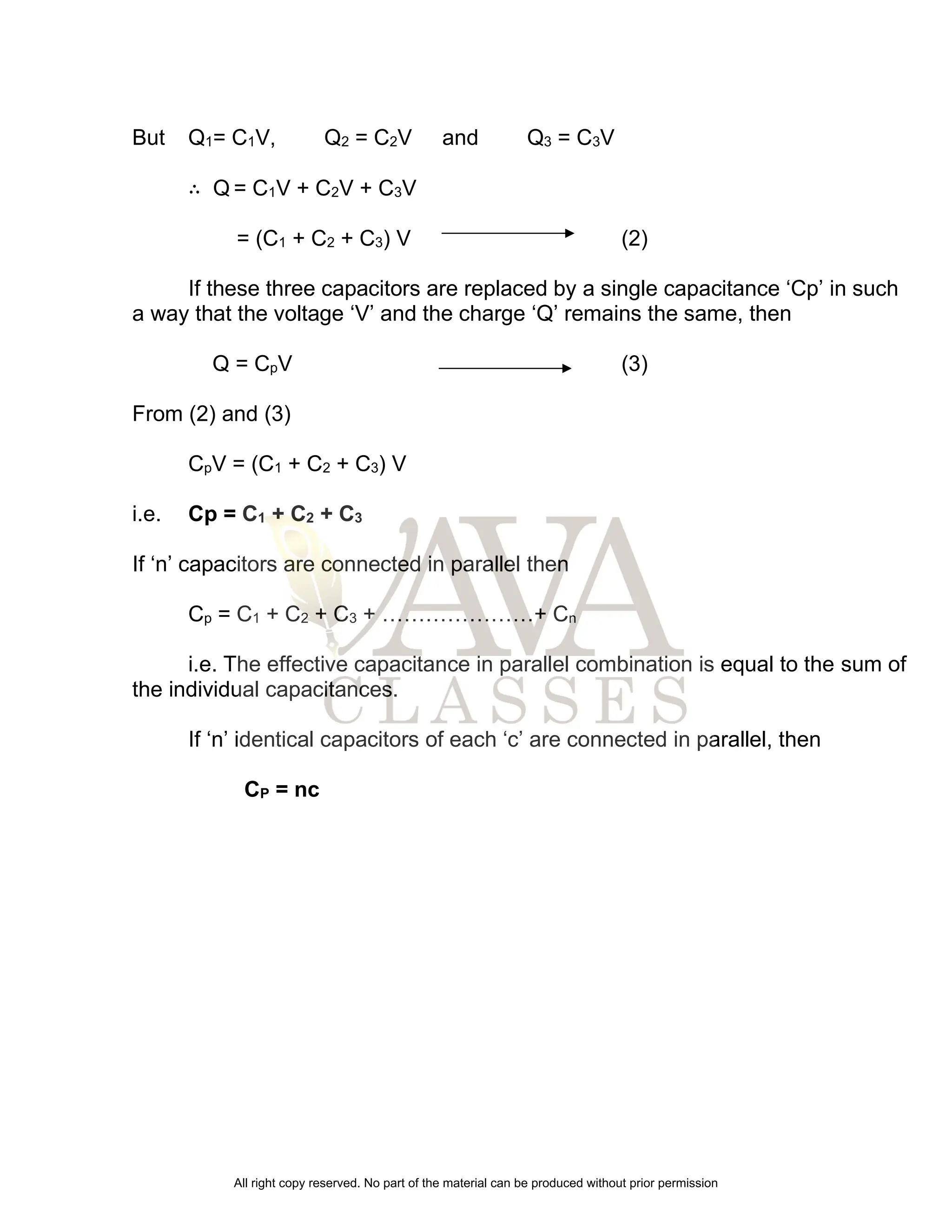

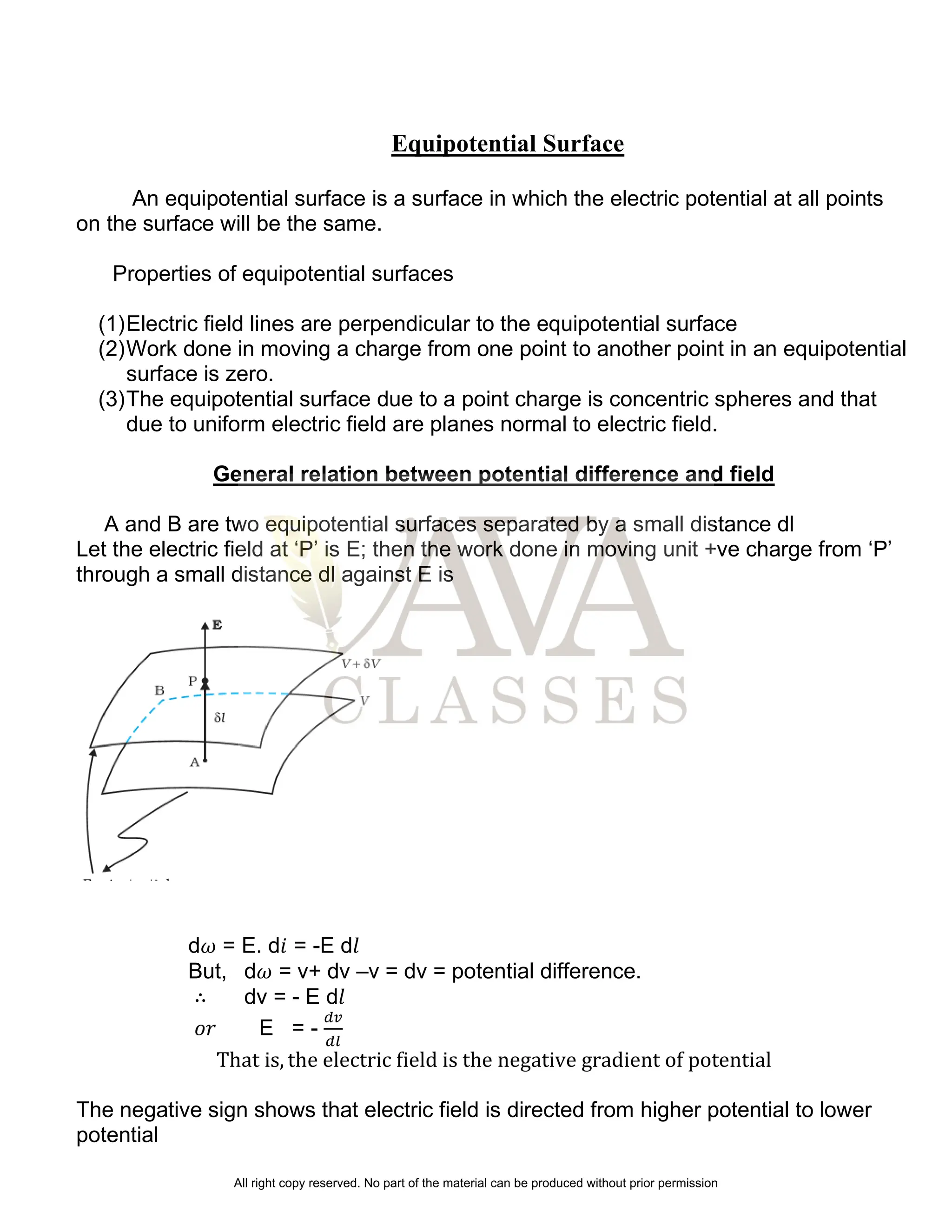
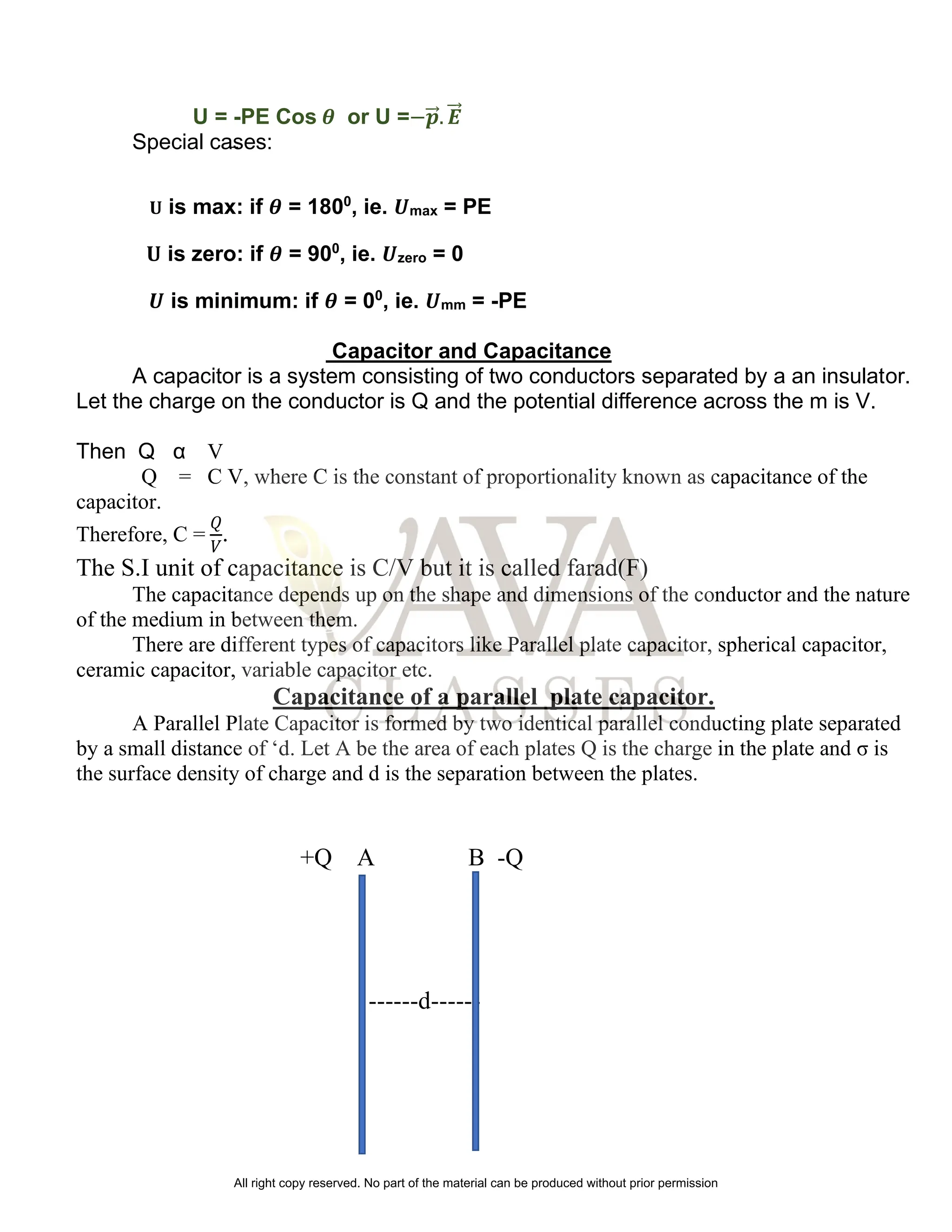
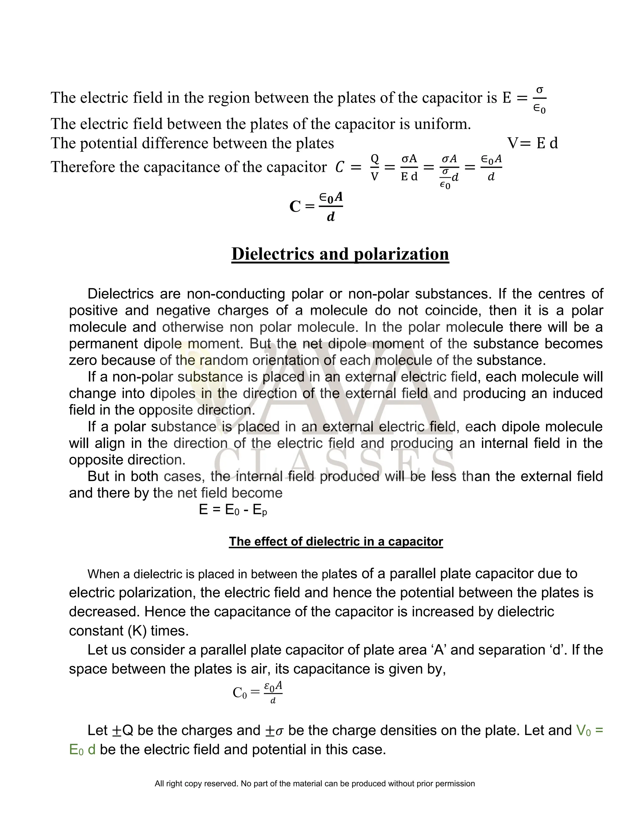
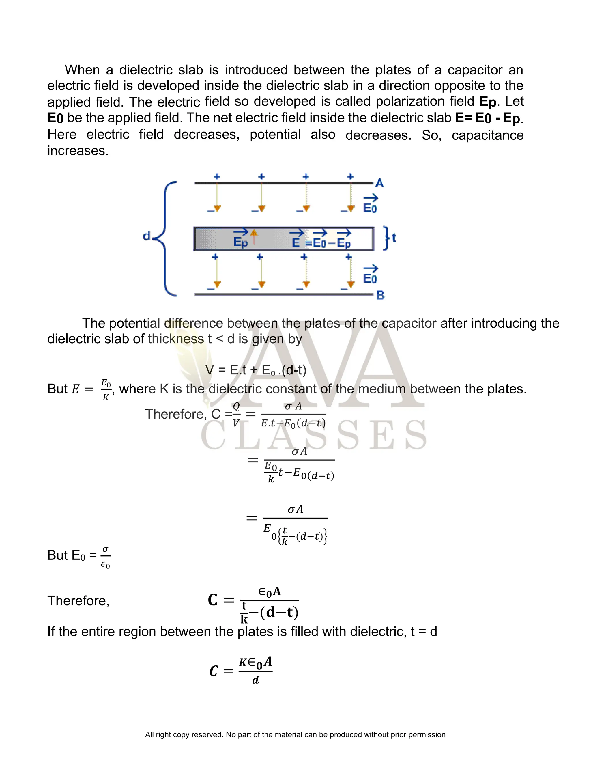
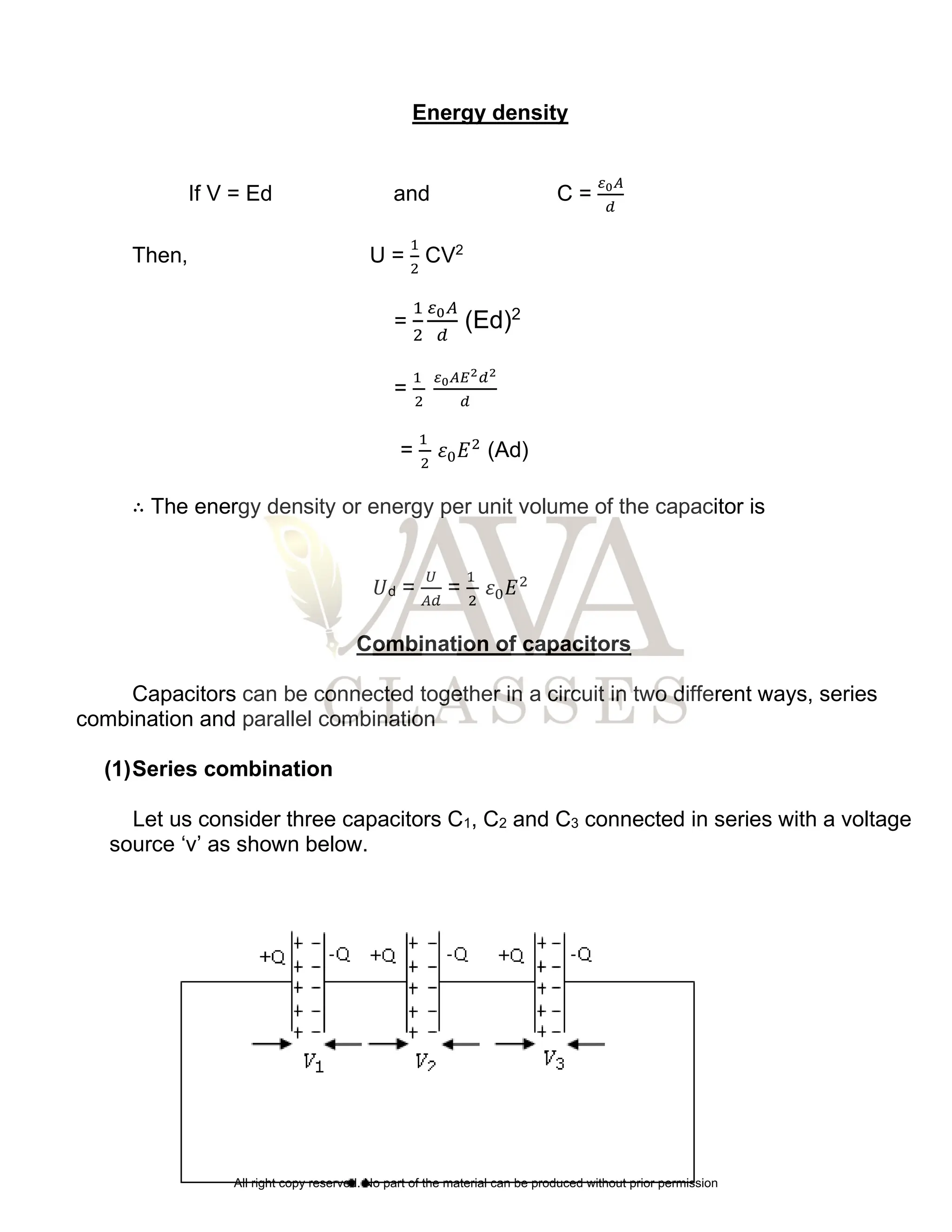
The document discusses electrostatic potential, capacitance, and electric fields, explaining the concepts of electric potential, potential difference, and the relationship between electric field and potential. It covers the potential due to point charges, dipoles, and multiple charges, as well as the energy stored in capacitors and their configurations. Additionally, the impact of dielectrics on capacitance and the energy density in capacitors are explained.