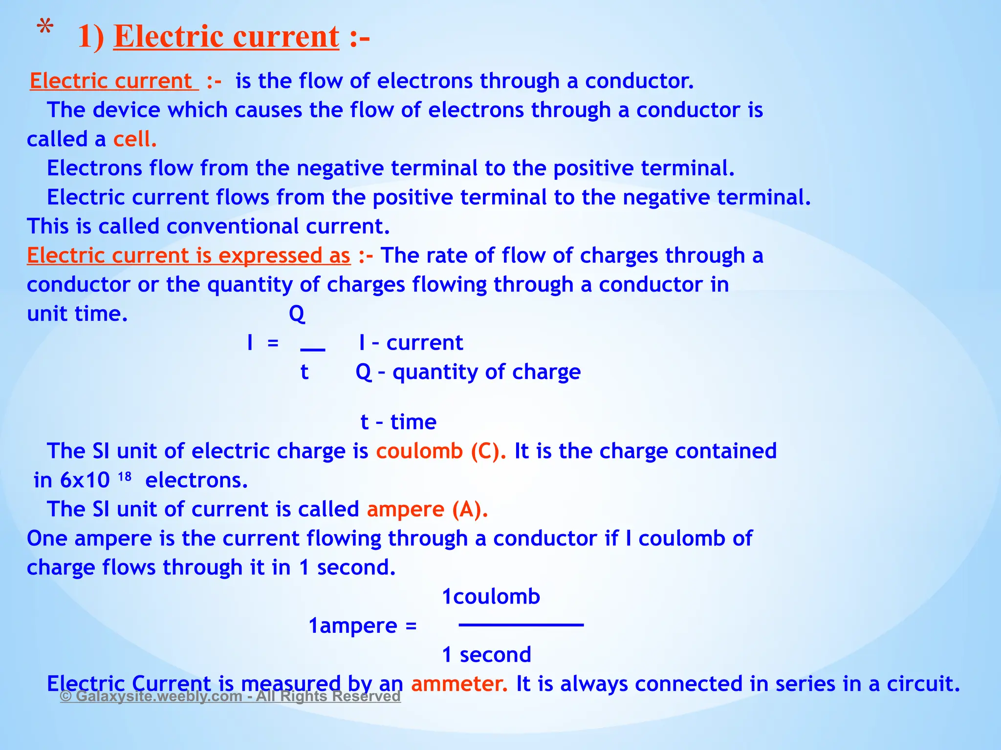
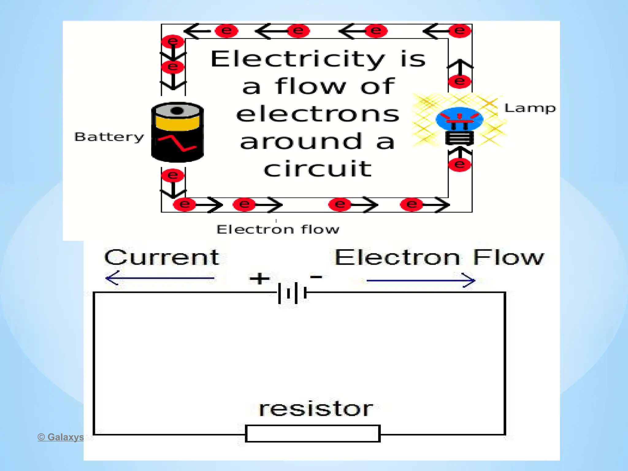
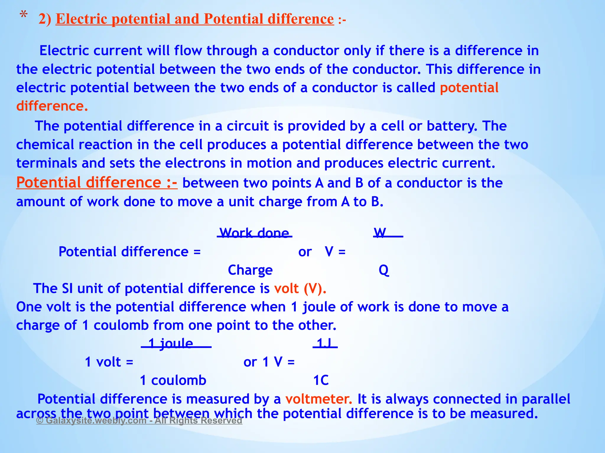
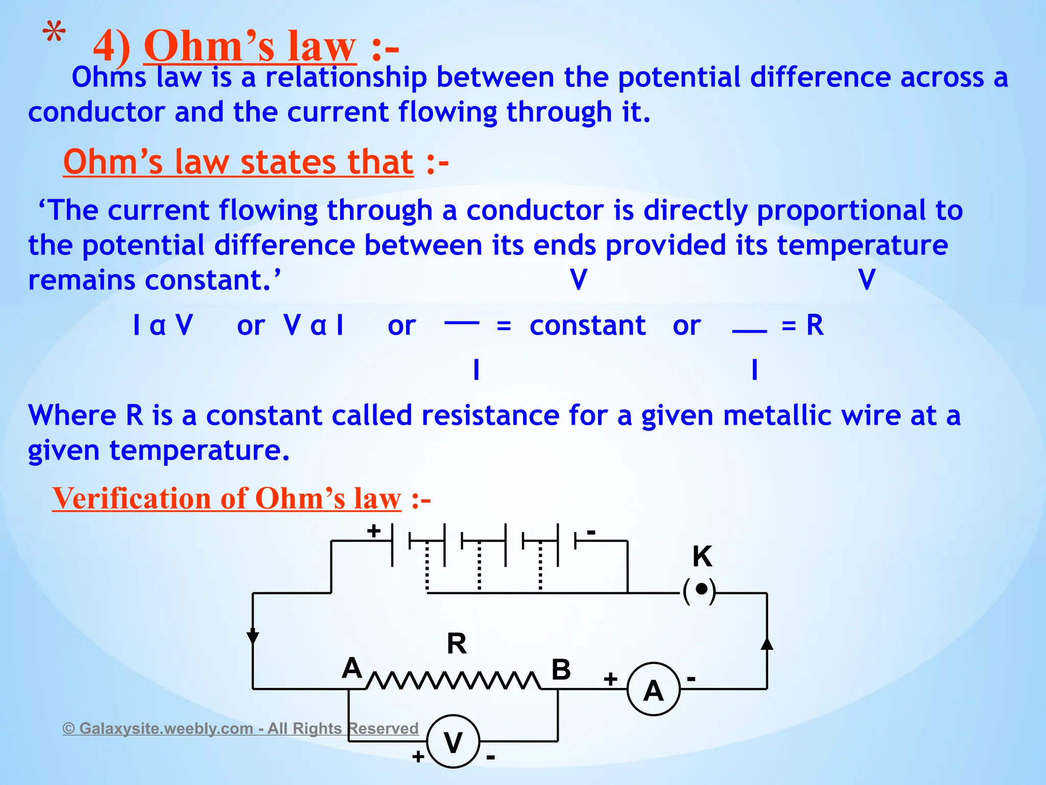
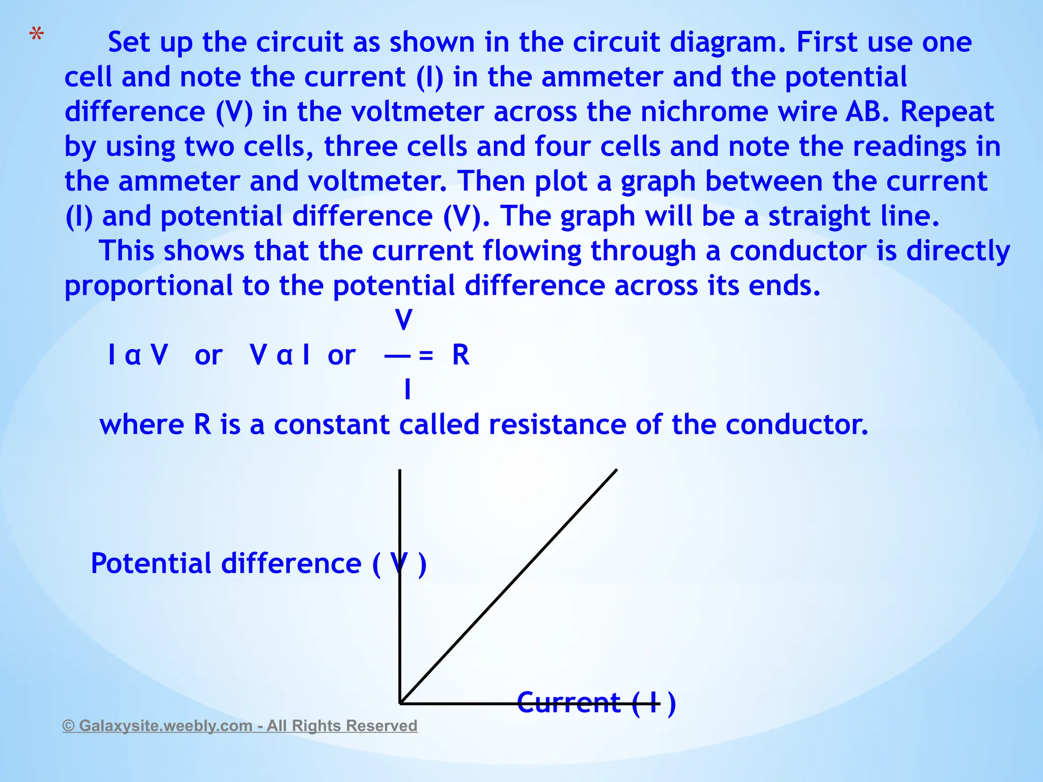
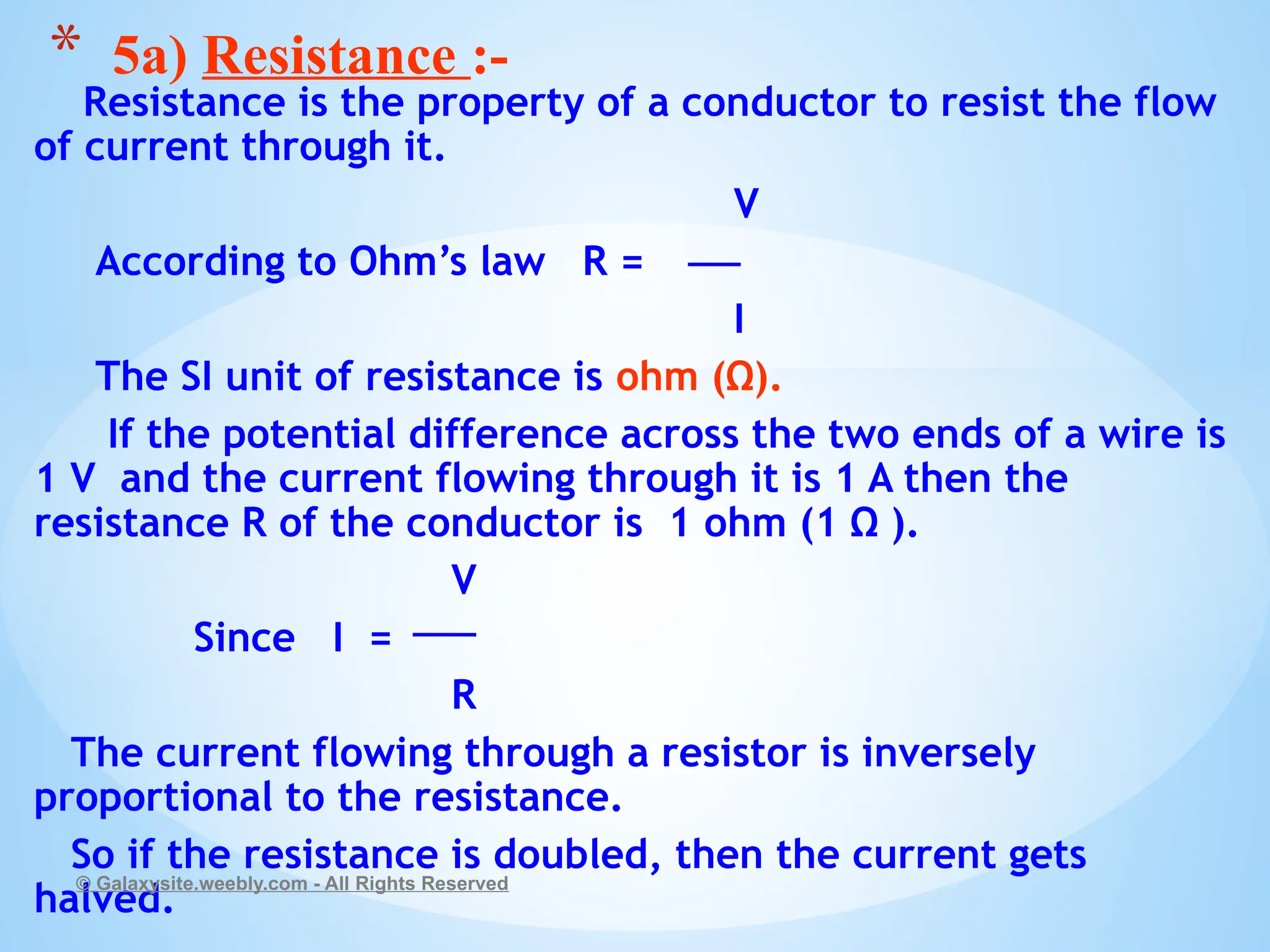
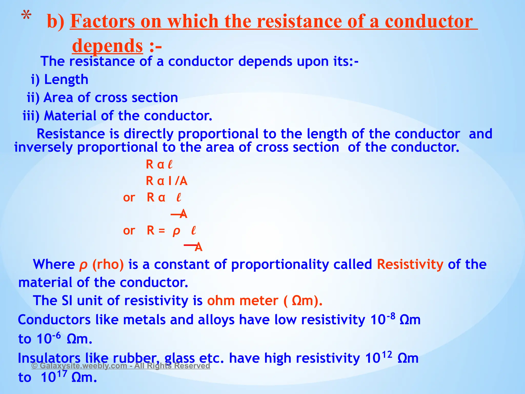
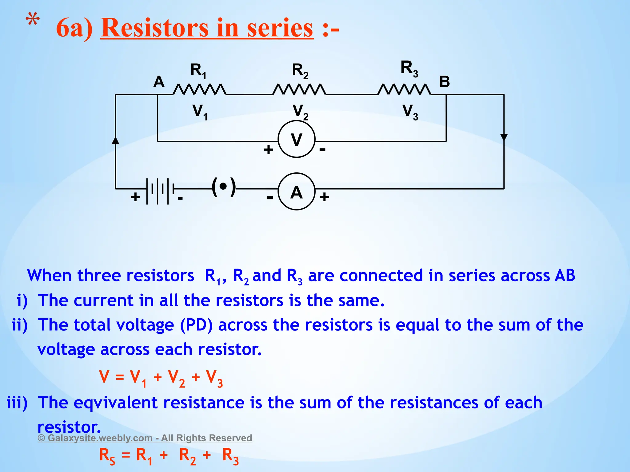
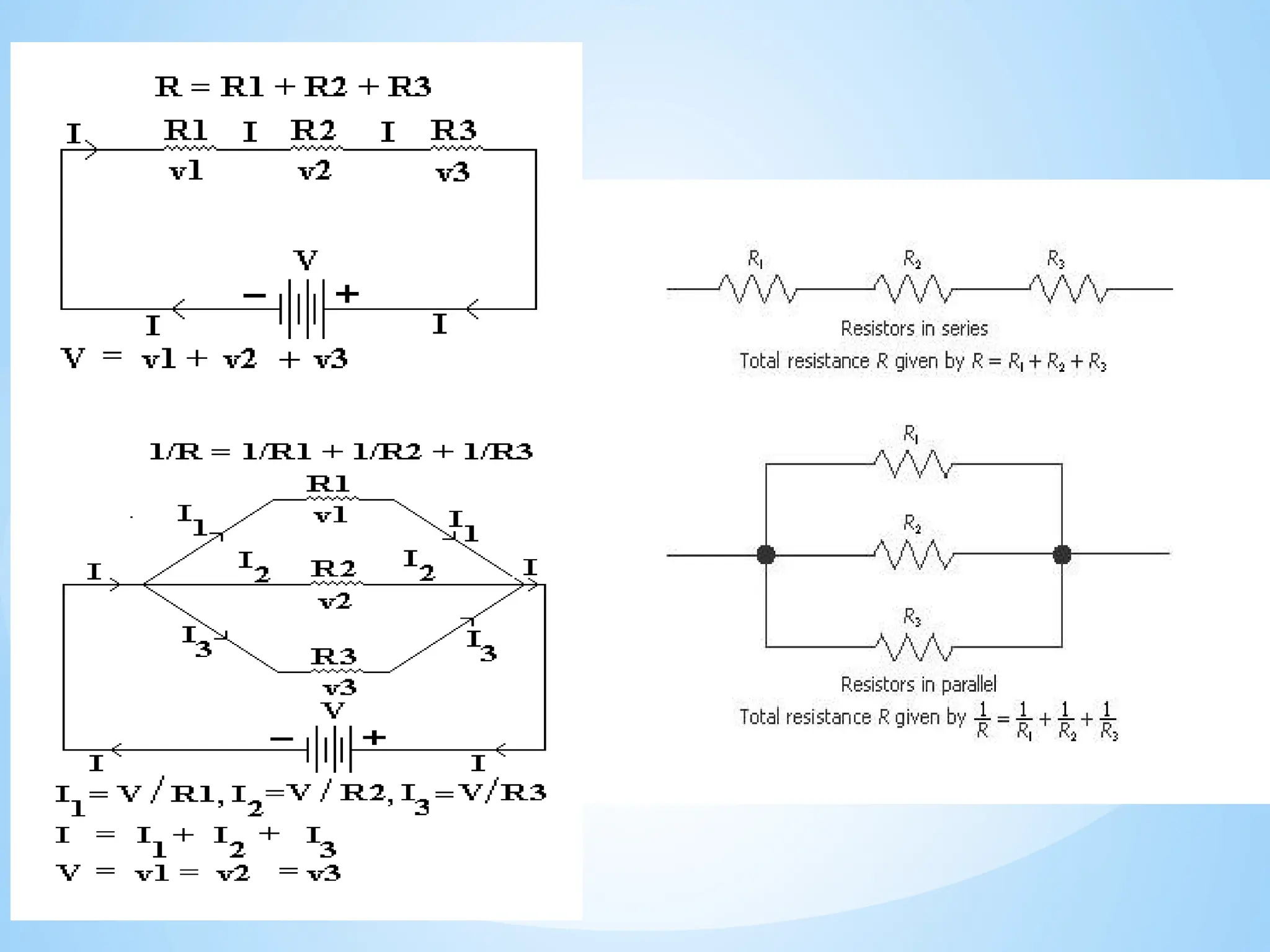
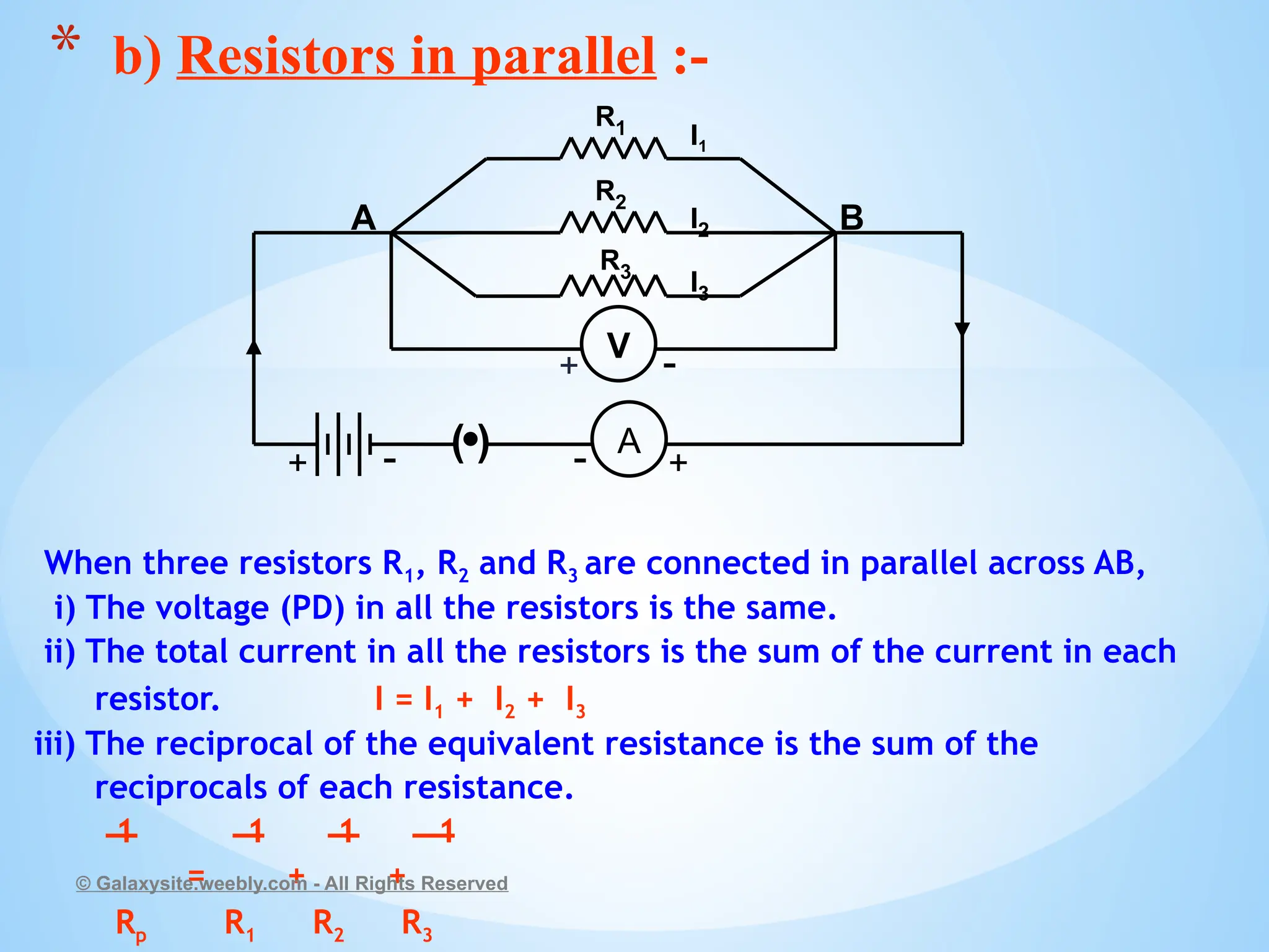
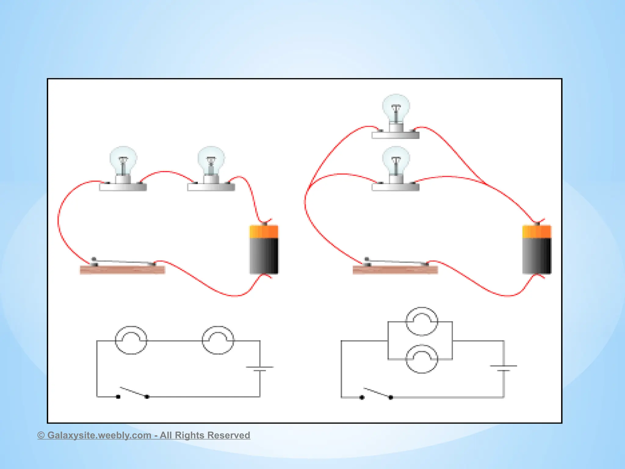
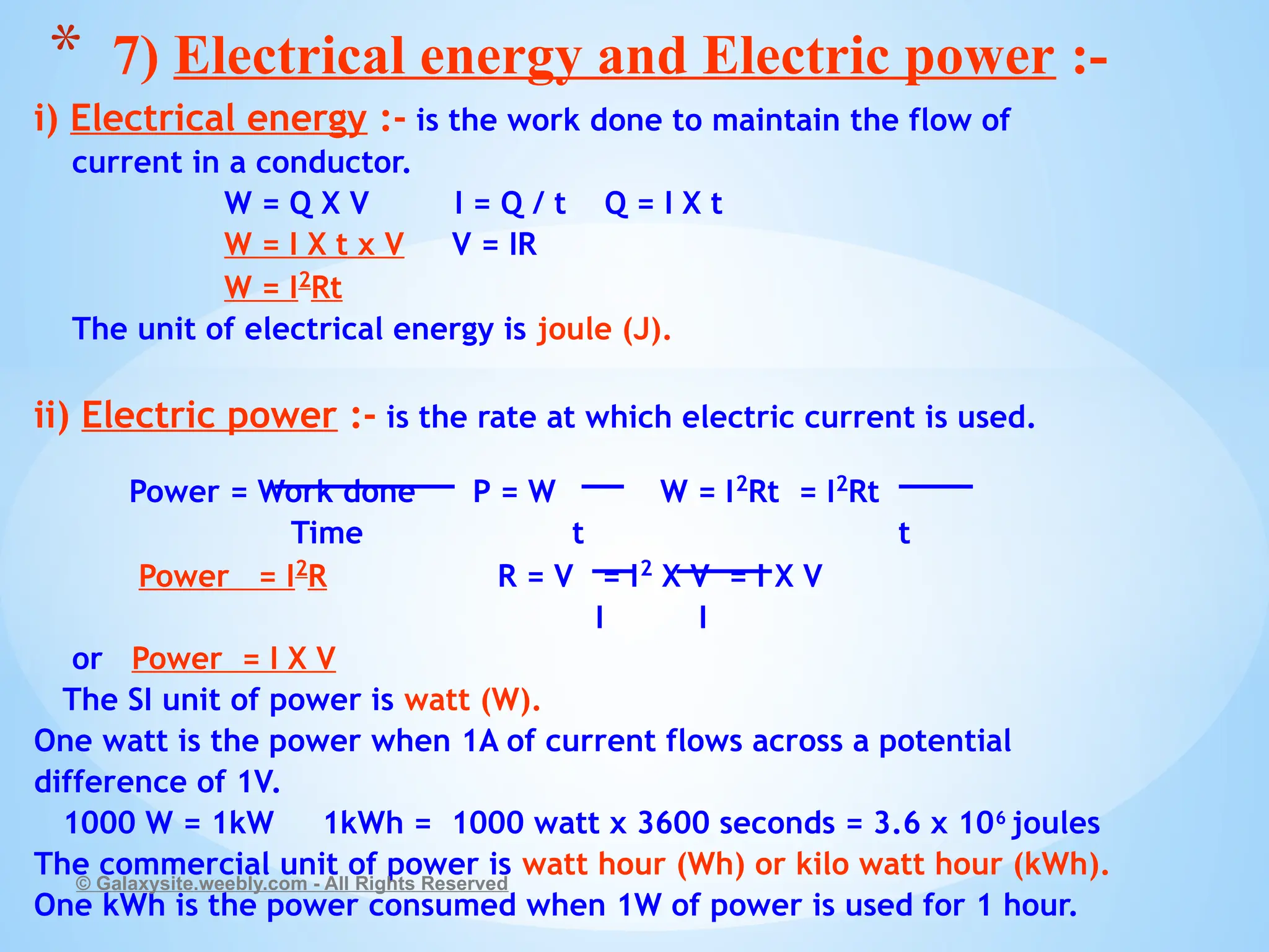
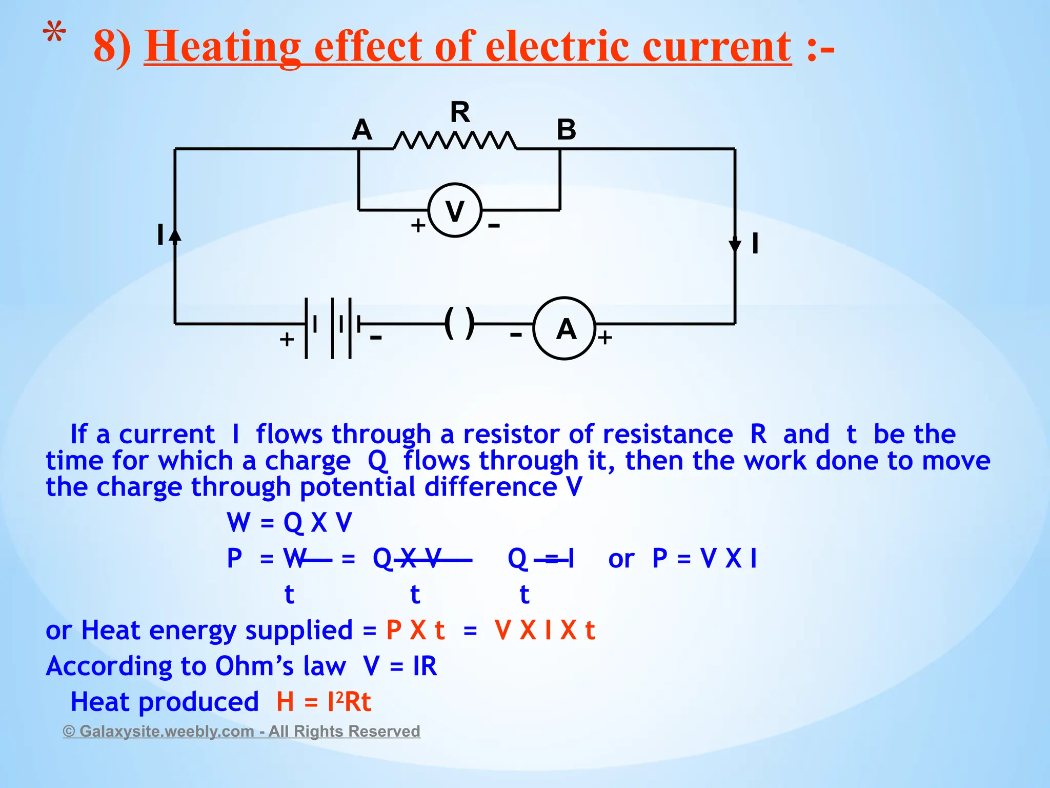
CLASS :- X
MADE BY :- MANAS MAHAJAN
© Galaxysite.weebly.com - All Rights Reserved
*CHAPTER -12
ELECTRICITY
Electric current :- is the flow of electrons through a conductor.
The device which causes the flow of electrons through a conductor is
called a cell.
Electrons flow from the negative terminal to the positive terminal.
Electric current flows from the positive terminal to the negative terminal.
This is called conventional current.
Electric current is expressed as :- The rate of flow of charges through a
conductor or the quantity of charges flowing through a conductor in
unit time. Q
I = I – current
t Q – quantity of charge
t – time
The SI unit of electric charge is coulomb (C). It is the charge contained
in 6x10 18
electrons.
The SI unit of current is called ampere (A).
One ampere is the current flowing through a conductor if I coulomb of
charge flows through it in 1 second.
1coulomb
1ampere =
1 second
Electric Current is measured by an ammeter. It is always connected in series in a circuit.
© Galaxysite.weebly.com - All Rights Reserved
* 1) Electric current :-
© Galaxysite.weebly.com - All Rights Reserved
Electric current will flow through a conductor only if there is a difference in
the electric potential between the two ends of the conductor. This difference in
electric potential between the two ends of a conductor is called potential
difference.
The potential difference in a circuit is provided by a cell or battery. The
chemical reaction in the cell produces a potential difference between the two
terminals and sets the electrons in motion and produces electric current.
Potential difference :- between two points A and B of a conductor is the
amount of work done to move a unit charge from A to B.
Work done W
Potential difference = or V =
Charge Q
The SI unit of potential difference is volt (V).
One volt is the potential difference when 1 joule of work is done to move a
charge of 1 coulomb from one point to the other.
1 joule 1J
1 volt = or 1 V =
1 coulomb 1C
Potential difference is measured by a voltmeter. It is always connected in parallel
across the two point between which the potential difference is to be measured.
© Galaxysite.weebly.com - All Rights Reserved
* 2) Electric potential and Potential difference :-
Electric circuit :- is a continuous and closed path of an
electric current.
A schematic diagram of an electric circuit comprising
of a cell, electric bulb, ammeter and plug key.
© Galaxysite.weebly.com - All Rights Reserved
* 3a) Electric circuit :-
A
+
-
+
-
bulb
cell
ammeter
plug key
An electric cell A battery or combination
of cells
Plug key or switch Plug key or switch
(open) (closed)
Electric bulb A resistor of
resistance R
Variable resistance or
or rheostat
Ammeter Voltmeter
A wire joint A wire crossing over
without joining
© Galaxysite.weebly.com - All Rights Reserved
* b) Symbols of components used in electric
circuits :-
A v
+ - -
+
+ - + -
© Galaxysite.weebly.com - All Rights Reserved
Ohms law is a relationship between the potential difference across a
conductor and the current flowing through it.
Ohm’s law states that :-
‘The current flowing through a conductor is directly proportional to
the potential difference between its ends provided its temperature
remains constant.’ V V
I α V or V α I or = constant or = R
I I
Where R is a constant called resistance for a given metallic wire at a
given temperature.
Verification of Ohm’s law :-
© Galaxysite.weebly.com - All Rights Reserved
* 4) Ohm’s law :-
V
A
+ -
+ -
+ -
R
K
A B
( )
* Set up the circuit as shown in the circuit diagram. First use one
cell and note the current (I) in the ammeter and the potential
difference (V) in the voltmeter across the nichrome wire AB. Repeat
by using two cells, three cells and four cells and note the readings in
the ammeter and voltmeter. Then plot a graph between the current
(I) and potential difference (V). The graph will be a straight line.
This shows that the current flowing through a conductor is directly
proportional to the potential difference across its ends.
V
I α V or V α I or = R
I
where R is a constant called resistance of the conductor.
Potential difference ( V )
Current ( I )
© Galaxysite.weebly.com - All Rights Reserved
Resistance is the property of a conductor to resist the flow
of current through it.
V
According to Ohm’s law R =
I
The SI unit of resistance is ohm (Ω).
If the potential difference across the two ends of a wire is
1 V and the current flowing through it is 1 A then the
resistance R of the conductor is 1 ohm (1 Ω ).
V
Since I =
R
The current flowing through a resistor is inversely
proportional to the resistance.
So if the resistance is doubled, then the current gets
halved.
© Galaxysite.weebly.com - All Rights Reserved
* 5a) Resistance :-
The resistance of a conductor depends upon its:-
i) Length
ii) Area of cross section
iii) Material of the conductor.
Resistance is directly proportional to the length of the conductor and
inversely proportional to the area of cross section of the conductor.
R α l
R α I /A
or R α l
A
or R = ρ l
A
Where ρ (rho) is a constant of proportionality called Resistivity of the
material of the conductor.
The SI unit of resistivity is ohm meter ( Ωm).
Conductors like metals and alloys have low resistivity 10-8
Ωm
to 10-6
Ωm.
Insulators like rubber, glass etc. have high resistivity 1012
Ωm
to 1017
Ωm.
© Galaxysite.weebly.com - All Rights Reserved
* b) Factors on which the resistance of a conductor
depends :-
When three resistors R1, R2 and R3 are connected in series across AB
i) The current in all the resistors is the same.
ii) The total voltage (PD) across the resistors is equal to the sum of the
voltage across each resistor.
V = V1 + V2 + V3
iii) The eqvivalent resistance is the sum of the resistances of each
resistor.
RS = R1 + R2 + R3
© Galaxysite.weebly.com - All Rights Reserved
* 6a) Resistors in series :-
( ) A
R1 R2
R3
+ +
-
-
V1 V2 V3
A B
V
+ -
© Galaxysite.weebly.com - All Rights Reserved
When three resistors R1, R2 and R3 are connected in parallel across AB,
i) The voltage (PD) in all the resistors is the same.
ii) The total current in all the resistors is the sum of the current in each
resistor. I = I1 + I2 + I3
iii) The reciprocal of the equivalent resistance is the sum of the
reciprocals of each resistance.
1 1 1 1
= + +
Rp R1 R2 R3
© Galaxysite.weebly.com - All Rights Reserved
* b) Resistors in parallel :-
R1
R3
R2
( ) A
I1
I2
I3
+
-
+ -
A B
V
+ -
© Galaxysite.weebly.com - All Rights Reserved
i) Electrical energy :- is the work done to maintain the flow of
current in a conductor.
W = Q X V I = Q / t Q = I X t
W = I X t x V V = IR
W = I2
Rt
The unit of electrical energy is joule (J).
ii) Electric power :- is the rate at which electric current is used.
Power = Work done P = W W = I2
Rt = I2
Rt
Time t t
Power = I2
R R = V = I2
X V = I X V
I I
or Power = I X V
The SI unit of power is watt (W).
One watt is the power when 1A of current flows across a potential
difference of 1V.
1000 W = 1kW 1kWh = 1000 watt x 3600 seconds = 3.6 x 10⁶
joules
The commercial unit of power is watt hour (Wh) or kilo watt hour (kWh).
One kWh is the power consumed when 1W of power is used for 1 hour.
© Galaxysite.weebly.com - All Rights Reserved
* 7) Electrical energy and Electric power :-
If a current I flows through a resistor of resistance R and t be the
time for which a charge Q flows through it, then the work done to move
the charge through potential difference V
W = Q X V
P = W = Q X V Q = I or P = V X I
t t t
or Heat energy supplied = P X t = V X I X t
According to Ohm’s law V = IR
Heat produced H = I2
Rt
© Galaxysite.weebly.com - All Rights Reserved
* 8) Heating effect of electric current :-
( ) A
V
R
A B
I I
+ -
+ -
+
-

Class 10 electricity chapter 11 high quality notes wowww

  • 1.
    CLASS :- X MADEBY :- MANAS MAHAJAN © Galaxysite.weebly.com - All Rights Reserved *CHAPTER -12 ELECTRICITY
  • 2.
    Electric current :-is the flow of electrons through a conductor. The device which causes the flow of electrons through a conductor is called a cell. Electrons flow from the negative terminal to the positive terminal. Electric current flows from the positive terminal to the negative terminal. This is called conventional current. Electric current is expressed as :- The rate of flow of charges through a conductor or the quantity of charges flowing through a conductor in unit time. Q I = I – current t Q – quantity of charge t – time The SI unit of electric charge is coulomb (C). It is the charge contained in 6x10 18 electrons. The SI unit of current is called ampere (A). One ampere is the current flowing through a conductor if I coulomb of charge flows through it in 1 second. 1coulomb 1ampere = 1 second Electric Current is measured by an ammeter. It is always connected in series in a circuit. © Galaxysite.weebly.com - All Rights Reserved * 1) Electric current :-
  • 3.
    © Galaxysite.weebly.com -All Rights Reserved
  • 4.
    Electric current willflow through a conductor only if there is a difference in the electric potential between the two ends of the conductor. This difference in electric potential between the two ends of a conductor is called potential difference. The potential difference in a circuit is provided by a cell or battery. The chemical reaction in the cell produces a potential difference between the two terminals and sets the electrons in motion and produces electric current. Potential difference :- between two points A and B of a conductor is the amount of work done to move a unit charge from A to B. Work done W Potential difference = or V = Charge Q The SI unit of potential difference is volt (V). One volt is the potential difference when 1 joule of work is done to move a charge of 1 coulomb from one point to the other. 1 joule 1J 1 volt = or 1 V = 1 coulomb 1C Potential difference is measured by a voltmeter. It is always connected in parallel across the two point between which the potential difference is to be measured. © Galaxysite.weebly.com - All Rights Reserved * 2) Electric potential and Potential difference :-
  • 5.
    Electric circuit :-is a continuous and closed path of an electric current. A schematic diagram of an electric circuit comprising of a cell, electric bulb, ammeter and plug key. © Galaxysite.weebly.com - All Rights Reserved * 3a) Electric circuit :- A + - + - bulb cell ammeter plug key
  • 6.
    An electric cellA battery or combination of cells Plug key or switch Plug key or switch (open) (closed) Electric bulb A resistor of resistance R Variable resistance or or rheostat Ammeter Voltmeter A wire joint A wire crossing over without joining © Galaxysite.weebly.com - All Rights Reserved * b) Symbols of components used in electric circuits :- A v + - - + + - + -
  • 7.
    © Galaxysite.weebly.com -All Rights Reserved
  • 8.
    © Galaxysite.weebly.com -All Rights Reserved
  • 9.
    Ohms law isa relationship between the potential difference across a conductor and the current flowing through it. Ohm’s law states that :- ‘The current flowing through a conductor is directly proportional to the potential difference between its ends provided its temperature remains constant.’ V V I α V or V α I or = constant or = R I I Where R is a constant called resistance for a given metallic wire at a given temperature. Verification of Ohm’s law :- © Galaxysite.weebly.com - All Rights Reserved * 4) Ohm’s law :- V A + - + - + - R K A B ( )
  • 10.
    * Set upthe circuit as shown in the circuit diagram. First use one cell and note the current (I) in the ammeter and the potential difference (V) in the voltmeter across the nichrome wire AB. Repeat by using two cells, three cells and four cells and note the readings in the ammeter and voltmeter. Then plot a graph between the current (I) and potential difference (V). The graph will be a straight line. This shows that the current flowing through a conductor is directly proportional to the potential difference across its ends. V I α V or V α I or = R I where R is a constant called resistance of the conductor. Potential difference ( V ) Current ( I ) © Galaxysite.weebly.com - All Rights Reserved
  • 11.
    Resistance is theproperty of a conductor to resist the flow of current through it. V According to Ohm’s law R = I The SI unit of resistance is ohm (Ω). If the potential difference across the two ends of a wire is 1 V and the current flowing through it is 1 A then the resistance R of the conductor is 1 ohm (1 Ω ). V Since I = R The current flowing through a resistor is inversely proportional to the resistance. So if the resistance is doubled, then the current gets halved. © Galaxysite.weebly.com - All Rights Reserved * 5a) Resistance :-
  • 12.
    The resistance ofa conductor depends upon its:- i) Length ii) Area of cross section iii) Material of the conductor. Resistance is directly proportional to the length of the conductor and inversely proportional to the area of cross section of the conductor. R α l R α I /A or R α l A or R = ρ l A Where ρ (rho) is a constant of proportionality called Resistivity of the material of the conductor. The SI unit of resistivity is ohm meter ( Ωm). Conductors like metals and alloys have low resistivity 10-8 Ωm to 10-6 Ωm. Insulators like rubber, glass etc. have high resistivity 1012 Ωm to 1017 Ωm. © Galaxysite.weebly.com - All Rights Reserved * b) Factors on which the resistance of a conductor depends :-
  • 13.
    When three resistorsR1, R2 and R3 are connected in series across AB i) The current in all the resistors is the same. ii) The total voltage (PD) across the resistors is equal to the sum of the voltage across each resistor. V = V1 + V2 + V3 iii) The eqvivalent resistance is the sum of the resistances of each resistor. RS = R1 + R2 + R3 © Galaxysite.weebly.com - All Rights Reserved * 6a) Resistors in series :- ( ) A R1 R2 R3 + + - - V1 V2 V3 A B V + -
  • 14.
    © Galaxysite.weebly.com -All Rights Reserved
  • 15.
    When three resistorsR1, R2 and R3 are connected in parallel across AB, i) The voltage (PD) in all the resistors is the same. ii) The total current in all the resistors is the sum of the current in each resistor. I = I1 + I2 + I3 iii) The reciprocal of the equivalent resistance is the sum of the reciprocals of each resistance. 1 1 1 1 = + + Rp R1 R2 R3 © Galaxysite.weebly.com - All Rights Reserved * b) Resistors in parallel :- R1 R3 R2 ( ) A I1 I2 I3 + - + - A B V + -
  • 16.
    © Galaxysite.weebly.com -All Rights Reserved
  • 17.
    i) Electrical energy:- is the work done to maintain the flow of current in a conductor. W = Q X V I = Q / t Q = I X t W = I X t x V V = IR W = I2 Rt The unit of electrical energy is joule (J). ii) Electric power :- is the rate at which electric current is used. Power = Work done P = W W = I2 Rt = I2 Rt Time t t Power = I2 R R = V = I2 X V = I X V I I or Power = I X V The SI unit of power is watt (W). One watt is the power when 1A of current flows across a potential difference of 1V. 1000 W = 1kW 1kWh = 1000 watt x 3600 seconds = 3.6 x 10⁶ joules The commercial unit of power is watt hour (Wh) or kilo watt hour (kWh). One kWh is the power consumed when 1W of power is used for 1 hour. © Galaxysite.weebly.com - All Rights Reserved * 7) Electrical energy and Electric power :-
  • 18.
    If a currentI flows through a resistor of resistance R and t be the time for which a charge Q flows through it, then the work done to move the charge through potential difference V W = Q X V P = W = Q X V Q = I or P = V X I t t t or Heat energy supplied = P X t = V X I X t According to Ohm’s law V = IR Heat produced H = I2 Rt © Galaxysite.weebly.com - All Rights Reserved * 8) Heating effect of electric current :- ( ) A V R A B I I + - + - + -