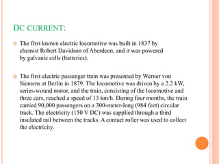
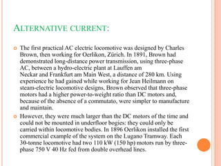
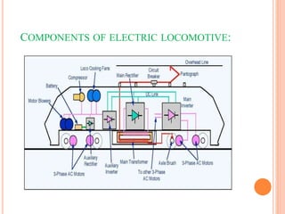
ELECTRIC
LOCOMOTIVES
Presented by:
B.Rama ganesh
Roll no:21C65A0201
INTRODUCTION:
 An electric locomotive is a locomotive powered by electricity
from overhead lines, a third rail or on-board energy storage such as
a battery or a supercapacitor. Locomotives with on-board
fuelled prime movers, such as diesel engines or gas turbines, are
classed as diesel-electric or gas turbine-electric and not as electric
locomotives, because the electric generator/motor combination
serves only a power transmission system.
DC CURRENT:
 The first known electric locomotive was built in 1837 by
chemist Robert Davidson of Aberdeen, and it was powered
by galvanic cells (batteries).
 The first electric passenger train was presented by Werner von
Siemens at Berlin in 1879. The locomotive was driven by a 2.2 kW,
series-wound motor, and the train, consisting of the locomotive and
three cars, reached a speed of 13 km/h. During four months, the train
carried 90,000 passengers on a 300-meter-long (984 feet) circular
track. The electricity (150 V DC) was supplied through a third
insulated rail between the tracks. A contact roller was used to collect
the electricity.
ALTERNATIVE CURRENT:
 The first practical AC electric locomotive was designed by Charles
Brown, then working for Oerlikon, Zürich. In 1891, Brown had
demonstrated long-distance power transmission, using three-phase
AC, between a hydro-electric plant at Lauffen am
Neckar and Frankfurt am Main West, a distance of 280 km. Using
experience he had gained while working for Jean Heilmann on
steam-electric locomotive designs, Brown observed that three-phase
motors had a higher power-to-weight ratio than DC motors and,
because of the absence of a commutato, were simpler to manufacture
and maintain.
 However, they were much larger than the DC motors of the time and
could not be mounted in underfloor bogies: they could only be
carried within locomotive bodies. In 1896 Oerlikon installed the first
commercial example of the system on the Lugano Tramway. Each
30-tonne locomotive had two 110 kW (150 hp) motors run by three-
phase 750 V 40 Hz fed from double overhead lines.
COMPONENTS OF ELECTRIC LOCOMOTIVE:
OVERHEAD LINES
 An overhead line or overhead wire is an electrical cable that is
used to transmit electrical energy to electric
locomotives, trolleybuses or trams. The generic term used by
the International Union of Railways for the technology is overhead
line.
PANTAGRAPH
 A pantograph is an apparatus mounted on the roof of an
electric train, tram or electric bus to collect power through contact
with an overhead line.
CIRCUIT BREAKER
 A circuit breaker is an electrical safety device designed to protect
an electrical circuit from damage caused by overcurrent. Its basic
function is to interrupt current flow to protect equipment and to
prevent the risk of fire. Unlike a fuse, which operates once and then
must be replaced, a circuit breaker can be reset (either manually or
automatically) to resume normal operation.
RECTIFIER
 A rectifier is an electrical device that converts alternating current (AC),
which periodically reverses direction, to direct current (DC), which flows in
only one direction. The reverse operation (converting DC to AC) is
performed by an inverter.
INVERTER
 A power inverter, inverter or invertor is a power electronic device
or circuitry that changes direct current (DC) to alternating
current (AC). The resulting AC frequency obtained depends on the
particular device employed. Inverters do the opposite
of rectifiers which were originally large electromechanical devices
converting AC to DC.
DC LINK
 A DC link is a connection which connects a rectifier and an
inverter. These links are found in converter circuits and in VFD
circuits. The AC supply of a specific frequency is converted into
DC. This DC, in turn, is converted into AC voltage. The DC link is
the connection between these two circuits.
COMPRESSORS
 A compressor is a mechanical device that increases the pressure
of a gas by reducing its volume. An air compressor is a specific
type of as compressor.
BATTERY
 A battery is a source of electric power consisting of one or more
electrochemical cells with external connections for powering
electrical devices. When a battery is supplying power, its positive
terminal is the cathode and its negative terminal is the anode.
MOTOR BLOWERS
 Traction motor cooling blower and its motor is one of the important
auxiliary machine. There are two traction motor cooling blowers fitted in a
locomotive. Each for cooling of one group of three traction motors. Failure
of one unit results into isolation of three traction motors.
AUXILIARY RECTIFIER
 In power train, the auxiliary rectifier is used to convert alternating
current into direct current. Auxiliary rectifiers are mostly used as high-
voltage direct-current power transmission systems and electronic
components of DC power supplies.
AUXILIARY INVERTER
 Auxiliary power supplies (static inverters) convert the power for interior
light, displays, air conditioning, etc. The propulsion inverter provides for
smooth ride comfort while the static inverter provides for interior comfort.
MAIN TRANSFORMER
 Current from the AC catenary (overhead line) flows through the primary
windings of a low-frequency transformer (LFT) to the rail (which
provides the return path). The reduced voltage available at the secondary
windings of the transformer is fed into a four-quadrant line chopper
converting it to DC-link voltage.
AXLE BRUSH
 The axle brushes are fitted to the rotating wheel, and the current is
transferred to the wheels through these carbon brushes, which slip over the
disk attached to the wheel axle . This is the simplest version of an electric
train.
3 PHASE AC MOTORS
 Nowadays, a Three-phase AC induction motor is used in the electric
locomotive train engine with IGBT-type converters and inverters. This kind
of AC induction motor is specially designed for traction applications. So, we
call this type of motor a Traction motor also.
3 PHASE INDUCTION MOTORS
Advantages
 Simple and rugged construction
 Less maintenance required
 High efficiency and good power factor
 Less expensive
 Self-starting torque
 Highly efficient and require minimal maintenance due to the lack of
brushes, commutators, or slip rings
 Robustness, withstanding overloads, voltage fluctuations, and operating
conditions that may damage other motor types
Disadvantages
 The three-phase of the induction motor requires constant speed.
 Due to the constant speed of the induction motor, speed control is very
difficult to maintain.
 In three phase induction motor, speed can not be easily controlled and
changed. By using the external circuit in the rotor circuit, you can control
speed (especially, in the slip ring induction motor).
 The induction motor operates only at a lagging power factor.
 The sensitivity of this motor torque is very high.
Speed-Torque charactristics
 The starting torque is 1.5 times the full-load torque, and the maximum
torque is 2.5 times the full-load torque.
 The speed of the motor decreases as the load on the shaft increases, until the
motor torque is equal to the load torque.
 The torque-speed curve is a straight line between the no-load and full-load
operating points.
Torque-Slip charactristics
Torque-slip charactristics are divided into three types
 Low-slip region: At synchronous speed, the slip s = 0, thus, the torque is 0.
 Medium-slip region: When the slip increases, the term (𝑠𝑋 2) 2 becomes
large so that 𝑅 22 may be neglected in comparison with (𝑠𝑋 2) 2.
 High-slip region: The torque decreases beyond the point of maximum
torque.
 The induction motor torque varies from zero to full load torque as the slip
varies.
REGENERATIVE BREAKING SYSTEM
 Regenerative braking is a technology that converts the kinetic energy of
the locomotive slowing into electrical energy that can be stored in its
batteries.
 When regenerative braking is employed, the current in the electric motors
is reversed, slowing down the train.
 At the same time, the electro motors generate electricity to be returned to
the power distribution system.
 The generated power is then smoothed and conditioned by the train control
system, stepped up by a transformer and returned to the outside world.
 Regenerative braking is a mature technology and can be more easily applied
to AC powered trains than to DC powered system.
Advantages of regenerative breaking
 The two main motivations to employ regenerative braking are energy and
reduced wear of mechanical brakes.
 The wear of the brake shoes and wheel tyres is reduced to considerable
extent, therefore, their life is increased and replacement cost is reduced.
 A part of energy is returned to the supply system, so energy consumption for
the run is considerably (about 20 to 30 per cent) reduced thereby affecting a
considerable saving in the operating cost.
 Higher value of braking retardation is obtained so that the vehicle can be
brought to rest quickly and running time is considerably reduced.
 Small amount of brake dust is produced when the mechanical brakes are
applied.
 Higher speeds are possible while going down the gradients because the high
braking retardation can be obtained with regenerative braking.
Merits of electric locomotives
 Better energy efficiency
 Lower emissions
 Lower operating costs
 Quieter operation
 More powerful
 More responsive and reliable
 Faster
 More efficient
electric locomotive

electric locomotive

  • 1.
  • 2.
    INTRODUCTION:  An electriclocomotive is a locomotive powered by electricity from overhead lines, a third rail or on-board energy storage such as a battery or a supercapacitor. Locomotives with on-board fuelled prime movers, such as diesel engines or gas turbines, are classed as diesel-electric or gas turbine-electric and not as electric locomotives, because the electric generator/motor combination serves only a power transmission system.
  • 3.
    DC CURRENT:  Thefirst known electric locomotive was built in 1837 by chemist Robert Davidson of Aberdeen, and it was powered by galvanic cells (batteries).  The first electric passenger train was presented by Werner von Siemens at Berlin in 1879. The locomotive was driven by a 2.2 kW, series-wound motor, and the train, consisting of the locomotive and three cars, reached a speed of 13 km/h. During four months, the train carried 90,000 passengers on a 300-meter-long (984 feet) circular track. The electricity (150 V DC) was supplied through a third insulated rail between the tracks. A contact roller was used to collect the electricity.
  • 4.
    ALTERNATIVE CURRENT:  Thefirst practical AC electric locomotive was designed by Charles Brown, then working for Oerlikon, Zürich. In 1891, Brown had demonstrated long-distance power transmission, using three-phase AC, between a hydro-electric plant at Lauffen am Neckar and Frankfurt am Main West, a distance of 280 km. Using experience he had gained while working for Jean Heilmann on steam-electric locomotive designs, Brown observed that three-phase motors had a higher power-to-weight ratio than DC motors and, because of the absence of a commutato, were simpler to manufacture and maintain.  However, they were much larger than the DC motors of the time and could not be mounted in underfloor bogies: they could only be carried within locomotive bodies. In 1896 Oerlikon installed the first commercial example of the system on the Lugano Tramway. Each 30-tonne locomotive had two 110 kW (150 hp) motors run by three- phase 750 V 40 Hz fed from double overhead lines.
  • 5.
  • 6.
    OVERHEAD LINES  Anoverhead line or overhead wire is an electrical cable that is used to transmit electrical energy to electric locomotives, trolleybuses or trams. The generic term used by the International Union of Railways for the technology is overhead line. PANTAGRAPH  A pantograph is an apparatus mounted on the roof of an electric train, tram or electric bus to collect power through contact with an overhead line. CIRCUIT BREAKER  A circuit breaker is an electrical safety device designed to protect an electrical circuit from damage caused by overcurrent. Its basic function is to interrupt current flow to protect equipment and to prevent the risk of fire. Unlike a fuse, which operates once and then must be replaced, a circuit breaker can be reset (either manually or automatically) to resume normal operation.
  • 7.
    RECTIFIER  A rectifieris an electrical device that converts alternating current (AC), which periodically reverses direction, to direct current (DC), which flows in only one direction. The reverse operation (converting DC to AC) is performed by an inverter. INVERTER  A power inverter, inverter or invertor is a power electronic device or circuitry that changes direct current (DC) to alternating current (AC). The resulting AC frequency obtained depends on the particular device employed. Inverters do the opposite of rectifiers which were originally large electromechanical devices converting AC to DC.
  • 8.
    DC LINK  ADC link is a connection which connects a rectifier and an inverter. These links are found in converter circuits and in VFD circuits. The AC supply of a specific frequency is converted into DC. This DC, in turn, is converted into AC voltage. The DC link is the connection between these two circuits. COMPRESSORS  A compressor is a mechanical device that increases the pressure of a gas by reducing its volume. An air compressor is a specific type of as compressor. BATTERY  A battery is a source of electric power consisting of one or more electrochemical cells with external connections for powering electrical devices. When a battery is supplying power, its positive terminal is the cathode and its negative terminal is the anode.
  • 9.
    MOTOR BLOWERS  Tractionmotor cooling blower and its motor is one of the important auxiliary machine. There are two traction motor cooling blowers fitted in a locomotive. Each for cooling of one group of three traction motors. Failure of one unit results into isolation of three traction motors. AUXILIARY RECTIFIER  In power train, the auxiliary rectifier is used to convert alternating current into direct current. Auxiliary rectifiers are mostly used as high- voltage direct-current power transmission systems and electronic components of DC power supplies. AUXILIARY INVERTER  Auxiliary power supplies (static inverters) convert the power for interior light, displays, air conditioning, etc. The propulsion inverter provides for smooth ride comfort while the static inverter provides for interior comfort.
  • 10.
    MAIN TRANSFORMER  Currentfrom the AC catenary (overhead line) flows through the primary windings of a low-frequency transformer (LFT) to the rail (which provides the return path). The reduced voltage available at the secondary windings of the transformer is fed into a four-quadrant line chopper converting it to DC-link voltage. AXLE BRUSH  The axle brushes are fitted to the rotating wheel, and the current is transferred to the wheels through these carbon brushes, which slip over the disk attached to the wheel axle . This is the simplest version of an electric train. 3 PHASE AC MOTORS  Nowadays, a Three-phase AC induction motor is used in the electric locomotive train engine with IGBT-type converters and inverters. This kind of AC induction motor is specially designed for traction applications. So, we call this type of motor a Traction motor also.
  • 11.
    3 PHASE INDUCTIONMOTORS Advantages  Simple and rugged construction  Less maintenance required  High efficiency and good power factor  Less expensive  Self-starting torque  Highly efficient and require minimal maintenance due to the lack of brushes, commutators, or slip rings  Robustness, withstanding overloads, voltage fluctuations, and operating conditions that may damage other motor types Disadvantages  The three-phase of the induction motor requires constant speed.  Due to the constant speed of the induction motor, speed control is very difficult to maintain.
  • 12.
     In threephase induction motor, speed can not be easily controlled and changed. By using the external circuit in the rotor circuit, you can control speed (especially, in the slip ring induction motor).  The induction motor operates only at a lagging power factor.  The sensitivity of this motor torque is very high. Speed-Torque charactristics  The starting torque is 1.5 times the full-load torque, and the maximum torque is 2.5 times the full-load torque.  The speed of the motor decreases as the load on the shaft increases, until the motor torque is equal to the load torque.  The torque-speed curve is a straight line between the no-load and full-load operating points. Torque-Slip charactristics Torque-slip charactristics are divided into three types  Low-slip region: At synchronous speed, the slip s = 0, thus, the torque is 0.
  • 13.
     Medium-slip region:When the slip increases, the term (𝑠𝑋 2) 2 becomes large so that 𝑅 22 may be neglected in comparison with (𝑠𝑋 2) 2.  High-slip region: The torque decreases beyond the point of maximum torque.  The induction motor torque varies from zero to full load torque as the slip varies.
  • 14.
    REGENERATIVE BREAKING SYSTEM Regenerative braking is a technology that converts the kinetic energy of the locomotive slowing into electrical energy that can be stored in its batteries.  When regenerative braking is employed, the current in the electric motors is reversed, slowing down the train.  At the same time, the electro motors generate electricity to be returned to the power distribution system.  The generated power is then smoothed and conditioned by the train control system, stepped up by a transformer and returned to the outside world.  Regenerative braking is a mature technology and can be more easily applied to AC powered trains than to DC powered system. Advantages of regenerative breaking  The two main motivations to employ regenerative braking are energy and reduced wear of mechanical brakes.  The wear of the brake shoes and wheel tyres is reduced to considerable extent, therefore, their life is increased and replacement cost is reduced.
  • 15.
     A partof energy is returned to the supply system, so energy consumption for the run is considerably (about 20 to 30 per cent) reduced thereby affecting a considerable saving in the operating cost.  Higher value of braking retardation is obtained so that the vehicle can be brought to rest quickly and running time is considerably reduced.  Small amount of brake dust is produced when the mechanical brakes are applied.  Higher speeds are possible while going down the gradients because the high braking retardation can be obtained with regenerative braking.
  • 16.
    Merits of electriclocomotives  Better energy efficiency  Lower emissions  Lower operating costs  Quieter operation  More powerful  More responsive and reliable  Faster  More efficient