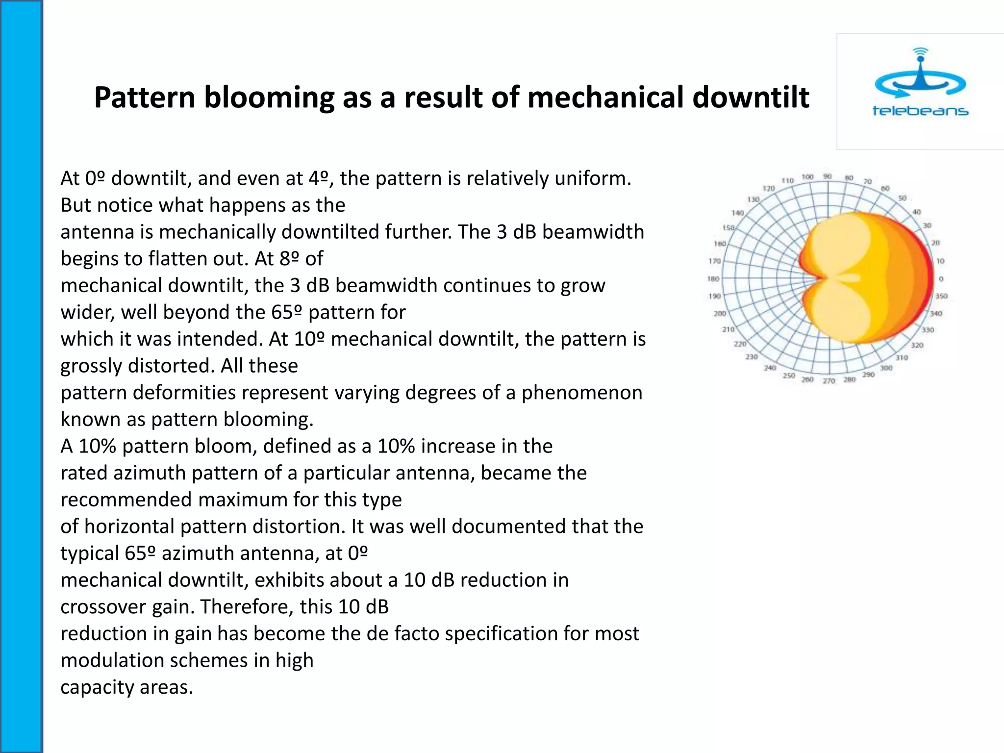
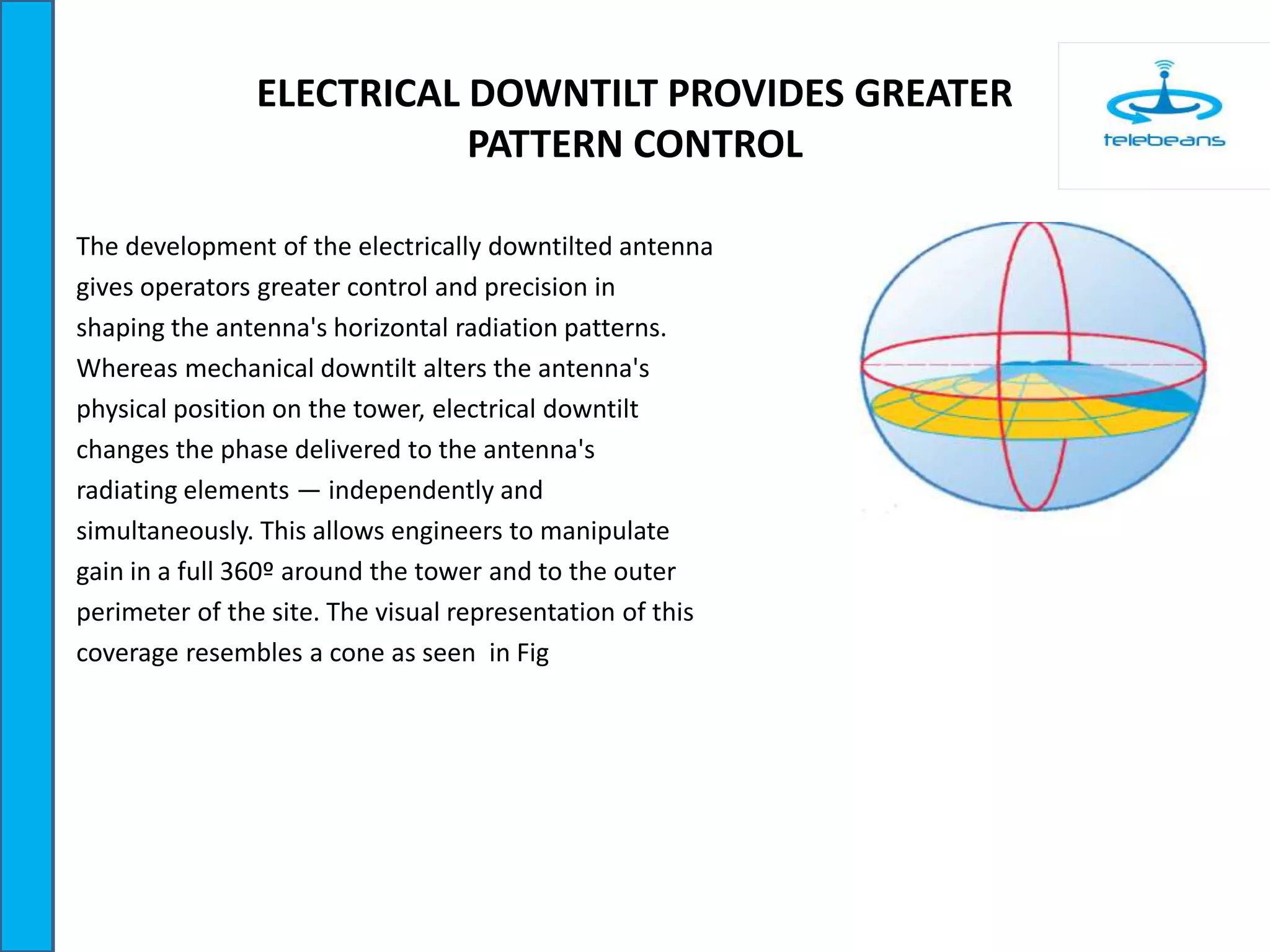
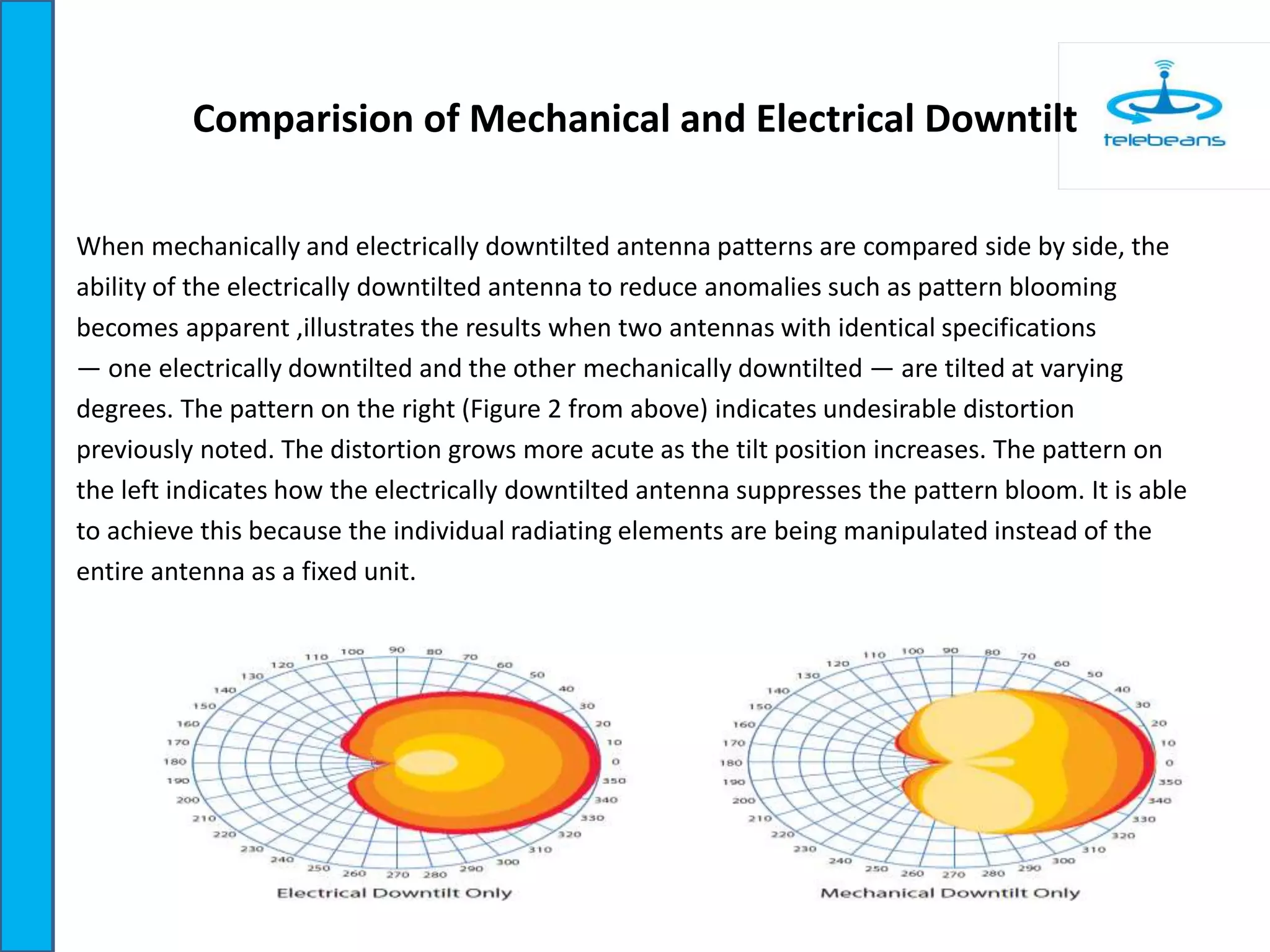
Downloaded 133 times
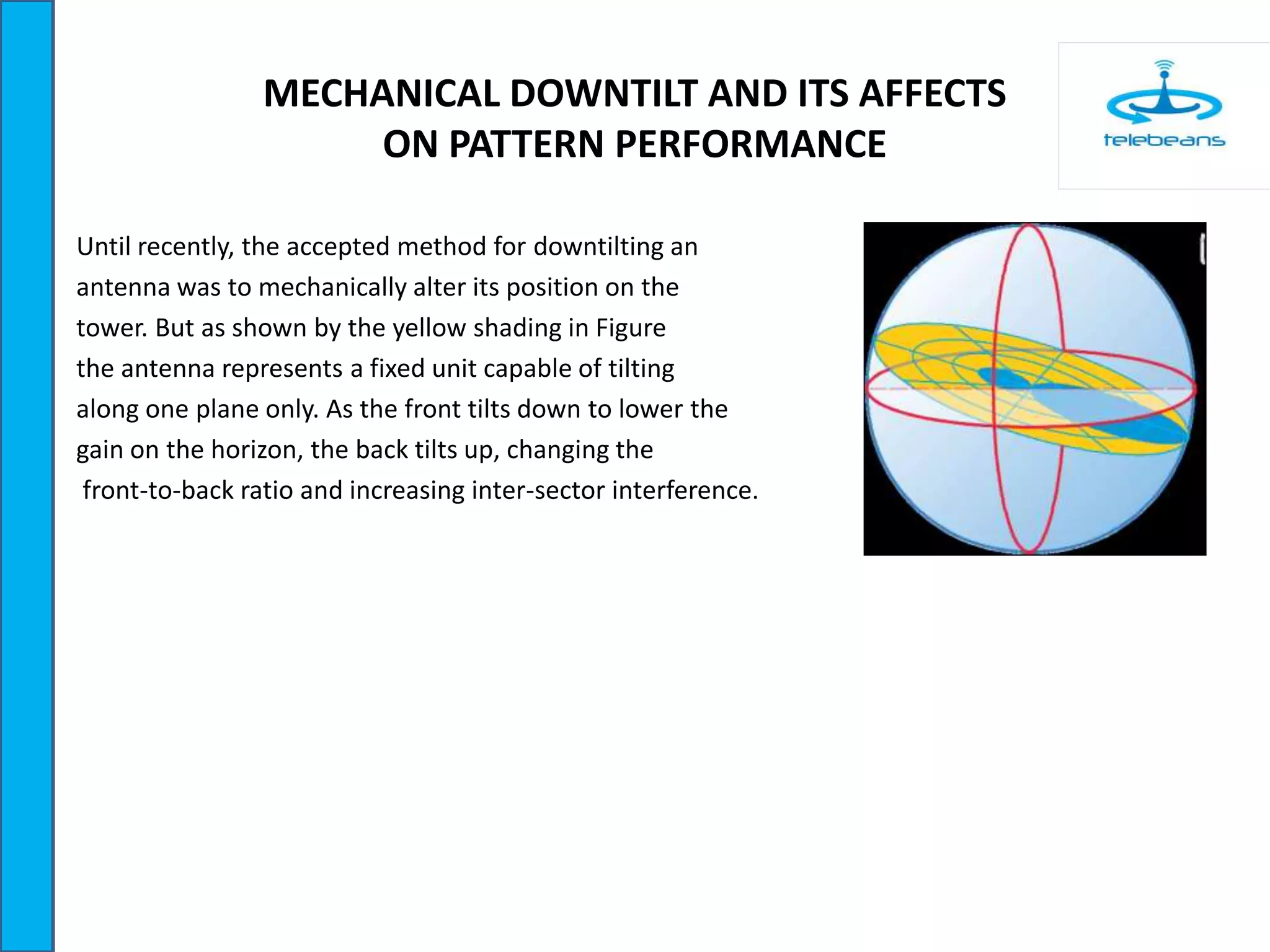


This document discusses the differences between mechanical and electrical downtilt of antennas and their effects on horizontal pattern performance. Mechanical downtilt physically tilts the entire antenna along a single plane, tilting the front down and back up, which can cause pattern blooming and irregularities that interfere with adjacent sectors. Electrical downtilt controls the phase to each radiating element independently, allowing more precise control over antenna patterns and reduction of interference. Comparisons show that electrically downtilted antennas suppress pattern blooming and distortions seen with increased mechanical downtilt, improving signal confinement and reducing inter-sector interference.