Riello master-switch-sts-3p
•
0 likes•309 views

Master Switch guarantees a source of redundant power, allowing the load to be switched b/w to alternative and independent power sources.

Recommended
Recommended
More Related Content
What's hot
What's hot (20)
Similar to Riello master-switch-sts-3p
Similar to Riello master-switch-sts-3p (20)
More from Electrical and renewable energy engineering
More from Electrical and renewable energy engineering (20)
Recently uploaded
Recently uploaded (20)
Riello master-switch-sts-3p
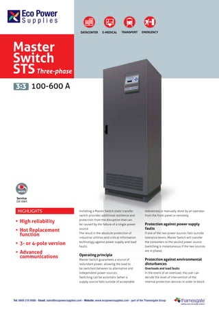
- 1. DATACENTER E-MEDICAL TRANSPORT EMERGENCY Master Switch STS Three-phase 3:3 100-600 A Service 1st start Highlights • High reliability • Hot Replacement function • 3- or 4-pole version • Advanced communications Installing a Master Switch static transfer switch provides additional resilience and protection from the disruption that can be caused by the failure of a single power source. The result is the absolute protection of industrial utilities and critical information technology against power supply and load faults. Operating principle Master Switch guarantees a source of redundant power, allowing the load to be switched between to alternative and independent power sources. Switching can be automatic (when a supply source falls outside of acceptable tolerances) or manually done by an operator from the front panel or remotely. Protection against power supply faults If one of the two power sources falls outside tolerance levels, Master Switch will transfer the consumers to the second power source (switching is instantaneous if the two sources are in phase). Protection against environmental disturbances Overloads and load faults In the event of an overload, the user can decide the level of intervention of the internal protection devices in order to block Tel: 0800 210 0088 - Email: sales@ecopowersupplies.com - Website: www.ecopowersupplies.com - part of the Thamesgate Group
- 2. Redundant design Power is supplied to the internal logic by two physically separate supply circuits that are fully independent and that can be replaced in “hot replacement” mode without causing power supply interruptions to the load. In the event that the power supplied by both sources fails, full system operation is guaranteed by the “Power Supply back up” function, which provides auxiliary power supply to the circuits from an external, independent power source. Master Switch is equipped with a dual redundant ventilation system known as: “fan redundance plus”. Thanks to this feature, and in the unlikely event that two fans fail at the same time, those remaining would still be able to dissipate the heat generated at nominal load and with an ambient temperature of up to 40° C. Also the fans can be replaced in “hot replacement” mode, ensuring continuity during the replacement operation. Superior protection In the event of an output short circuit, Master Switch blocks the transfer between the two power sources, eliminating the risk of propagating the short circuit and its effects to the other loads. A back feed control circuit ensures the LEDs S2 The layout of the moving components and parts is designed to ensure easy frontal access: • power cable connections that are easily accessed with entry from below • boards housed in a dedicated area for rapid diagnosis / replacement • all parts subject to monitoring, maintenance and/or replacement. S4-2 Advanced communications Master Switch provides information, measurements, statuses, and alarms via the LCD display. The STS is compatible with PowerShield3 supervision and shutdown software for Windows operating systems 8, 7, 2008, Vista, 2003, XP, Linux, Mac OS X and Sun Solaris. OPTIONS Software PowerShield3 PRODUCT ACCESSORIES RS232 serial duplicator “no neutral on input” kit IP rating IP31 ACCESSORIES NETMAN 101 PLUS multicom 301 multicom 351 DIMENSIONS MTS 100 MTS 150 MTS 200 - MTS 250 MTS 300 - MTS 400 685 0 53 685 0 58 Static transfer switch SS2 closed L7 Alarm indicator L8 S4-1 3P + N Output Static transfer switch SS1 closed L6 SS1 S3 S2 Present L5 SS2 Output Switch 1 S1 Present L4 S1 Maintenance Switch 1 S2 Priority Source L3 Input MCCB 2 Maintenance Switch 2 S1 Priority Source L2 Accessibility FUNCTION L1 Input MCCB 1 MTS 600 1900 Microprocessor control logic ensures: • Fast and safe switching between power sources • Monitoring of all parameters via LCD display • Constant monitoring of SCR operation • Advanced remote diagnostics (RS232 and TCP/IP). 3P + N Source 2 Input 1770 Total microprocessor control 3P + N Source 1 Input automatic intervention of the protection devices when a return of power to one of the two Master Switch inputs is detected. 1500 the power supply. In the extreme case of a downstream short circuit, Master Switch disconnects the load in order to avoid jeopardising the operation of the other loads (i.e. in the event of poor selectivity of the protection devices). Output selector ON/OFF 5 function keys and LCD operation Tel: 0800 210 0088 - Email: sales@ecopowersupplies.com - Website: www.ecopowersupplies.com - part of the Thamesgate Group 950 0 73
- 3. MASTER SWITCH in REDUNDANT mode The secondary power source [AS], although highly reliable, only powers the load in the event of a failure with the priority power source [PS], ensuring maximum redundancy and power quality to the loads. [PS] [AS] USER 1 [AS] = Secondary [PS] = Priority MASTER SWITCH in CROSS FEEDING Mode The two sources power critical loads using Master Switches configured to selected one of the two power sources as the priority source [PS]. In case of a failure in one of two sources, the other will be able to supply power to all the loads connected to the system). [PS] [AS] USER 1 [AS] [PS] [AS] = Secondary [PS] = Priority USER 2 MASTER SWITCH in BACK-UP mode Independent separate lines Master Switches power utilities via the priority energy source [PS]; the secondary energy source [AS] is made up of independent, separate power sources and to make up for any faults in the priority power source [PS]. [PS] [AS] USER 1 [PS] [AS] [AS] = Secondary [PS] = Priority USER 2 DYNAMIC DUAL BUS CONFIGURATION Bypass 1 System B Mains Mains UPS2A Mains UPS1B Battery UPS1A Bypass 2 UPS2B Battery Mains Battery System A Battery The Riello UPS solution guarantees maximum reliability and ensures continuity of power supply under all operating conditions thanks to the UGS option that keeps the two systems, A and B, perfectly synchronised. The flexibility of the UGS system ensures synchronism between the sources even when one of the two systems is not a Riello UPS model, but made by another manufacturer, or when the input sources are not from uninterruptible power supplies. UGS Sinchroniser Static Transfer SWITCH Load 3 Load 1 Static Transfer SWITCH Load 2 Load 4 Tel: 0800 210 0088 - Email: sales@ecopowersupplies.com - Website: www.ecopowersupplies.com - part of the Thamesgate Group
- 4. MODELS NOMINAL CURRENT MTS 100 MTS 150 MTS 200 MTS 250 MTS 300 MTS 400 MTS 600 100 A 150 A 200 A 250 A 300 A 400 A 600 A 55 dBA 57 dBA INPUT Nominal voltage - sources S1/S2 380 - 400 - 415 Vac three-phase + N Input voltage tolerance 180-264 Vac (selectable) Switched input phases 3+N (4-pole) - 3 (3-pole) Nominal frequency 50/60 Hz Input frequency tolerance range +/-10% (selectable) Distribution compatibility IT, TT, TNS, TNC OPERATING SPECIFICATIONS Transfer type “Break Before Make” (no overlapping sources) Available transfer methods Automatic / Manual / Remote Transfer time following source failure < 4 msec (S1/S2 synchronised) 10 msec (S1/S2 non synchronised) ENVIRONMENTAL SPECIFICATIONS Efficiency at full load Noise at 1 m from front (from 0 to full load) > 99% 55 dBA 55 dBA 55 dBA Storage temperature 55 dBA 55 dBA -10 °C up to +50 °C Operating temperature O °C - 40 °C Relative humidity 95% non-condensing Max. installation height 1000 m at nominal power (-1% power for every 100 m above 1000 m) - Max 4000 m Reference standard EN 62310-1 (safety) EN 62310-2 (electro-magnetic compatibility) INFO FOR INSTALLATION Weight (kg) Dimensions (WxDxH) (mm) Colour IP rating Moving the STS 155 160 685 x 530 x 1500 205 210 235 685 x 580 x 1770 RAL 7016 IP 20 transpallet Tel: 0800 210 0088 - Email: sales@ecopowersupplies.com - Website: www.ecopowersupplies.com - part of the Thamesgate Group 240 375 950 x 730 x 1900