This document summarizes research on improving the radiation pattern of a Yagi-Uda antenna through simulation and design modifications. The researchers designed a Yagi-Uda antenna in MATLAB and made improvements to previous designs to achieve better electric field intensity and directivity. Their approach involved simulating the radiation pattern of a symmetrically shaped antenna and then maximizing output parameters by using techniques like reflector surfaces to reduce loss from side lobes. They provide mathematical analysis of the Yagi-Uda antenna's radiation pattern and current distribution based on Pocklington's integral equation.
Beam Steering Using the Active Element Pattern of Antenna ArrayTELKOMNIKA JOURNAL
An antenna array is a set of a combination of two or more antennas in order to achieve improved
performance over a single antenna. This paper investigates the beam steering technique using the active
element pattern of dipole antenna array. The radiation pattern of the array can be obtain by using the
active element pattern method multiplies with the array factor. The active element pattern is crucial as the
mutual coupling effect is considered, and it will lead to an accurate radiation pattern, especially in
determining direction of arrival (DoA) of a signal. A conventional method such as the pattern multiplication
method ignores the coupling effect which is essential especially for closely spaced antenna arrays. The
comparison between both techniques has been performed for better performance. It is observed that the
active element pattern influenced the radiation pattern of antenna arrays, especially at the side lobe level.
Then, the beam of the 3x3 dipole antenna array has been steered to an angle of 60° using three
techniques; Uniform, Chebyshev and Binomial distribution. All of these are accomplished using CST and
Matlab software
Particle Swarm Optimization with Constriction Factor and Inertia Weight Appro...IDES Editor
In this paper, an evolutionary optimization
technique, Particle Swarm Optimization with Constriction
Factor and Inertia Weight Approach (PSOCFIWA) is adopted
for the complex synthesis of three-ring Concentric Circular
Antenna Arrays (CCAA) with non-isotropic elements and
without and with central element feeding. It is shown that by
selection of a fitness function which controls more than one
parameter of the array pattern, and also by proper setting of
weight factors in fitness function, one can achieve very good
results. For each optimal design, optimal current excitation
weights and optimal radii are determined having the objective
of maximum Sidelobe Level (SLL) reduction. The extensive
computational results show that the CCAA designs having
central element feeding with non-isotropic elements yield
much more reduction in SLL as compared to the same not
having central element feeding. Moreover, the particular
CCAA containing 4, 6 and 8 number of elements in three
successive rings along with central element feeding yields
grand minimum SLL (-46.4 dB). Standard Particle Swarm
Optimization (PSO) is adopted to compare the results of the
PSOCFIWA algorithm.
This document discusses plane wave reflection from a media interface. It begins by introducing the concepts of reflection and transmission coefficients which describe how much of an incident wave is reflected or transmitted at a boundary. It then examines plane wave reflection at normal incidence, deriving expressions for the reflected and transmitted electric and magnetic fields in two lossy media. Boundary conditions requiring the tangential field components to be continuous are applied to obtain equations relating the reflection and transmission coefficients to the material properties on either side of the interface.
A new design of a microstrip rectenna at 5.8 GHz for wireless power transmiss...IJECEIAES
Due to the ever-increasing power demand, the need of electricity and eco-friendly power in every nook and corner of the world, many reaserch topics have been devoted to deal with this problematic. This paper is taking part of the proposed solutions with the presentation of a novel 5.8 GHz rectenna system for wireless power transmission applications. In one hand, a miniaturized 5.8 GHz circular polarized patch antenna has been designed and simulated by using the Advanced Design System (ADS). In the other hand, a rectifier structure has been investigated and optimized by the use of the Harmonic Balance method available in ADS. The circuit is based on 5 HSMS2820 Schottky diodes implemented in a voltage multiplier topology and a load resistance of 1 KOhm. Both of the structures have been validated by simulation and experimental results and good agreement has been concluded.
Design Optimization of Energy and Delay Efficient Wireless Sensor Network wit...IOSR Journals
This document describes a proposed approach to optimize energy efficiency and delay in wireless sensor networks using a combination of particle swarm optimization and cluster-based least spanning tree algorithms. It begins with background on challenges in wireless sensor networks related to limited energy resources. It then presents the system model, including the network and radio power models. The document goes on to describe particle swarm optimization and how it can be applied to set up energy-efficient clusters in each round. The goal is to select cluster heads that minimize a cost function balancing energy usage and delay.
This document discusses electromagnetic field theory and computational electromagnetics. It introduces electromagnetic theory, which is divided into electrostatics, magnetostatics, and time-varying fields. Computational electromagnetics is presented as a way to numerically solve electromagnetic problems using computers. Different types of equation solvers are described, including integral equation solvers and differential equation solvers. General coordinate systems and transformations between coordinate systems are also covered.
Enhancing the Radiation Pattern of Phase Array Antenna Using Particle Swarm O...IOSR Journals
The document describes a study that uses particle swarm optimization to enhance the radiation pattern of a phase array antenna by minimizing sidelobe levels. It first provides background on issues with high sidelobes in phase array antennas, such as power losses and interference. It then summarizes previous research using techniques like genetic algorithms for antenna array optimization. The study models the radiation pattern of linear arrays with different element numbers and calculates gain, finding that gain increases with more elements. However, sidelobe levels also increase relatively. Therefore, the study proposes using particle swarm optimization to optimize current excitation and control sidelobe levels while maintaining a narrow beamwidth.
Measurements Of Dielectric Constant Of Solid Material (Leather Belt) At X-Ba...IJMER
This article discusses the experimental measurement technique for dielectric constant (i.e.
permittivity ) of leather belt at X-band. This measurement play selection of dielectric constant for
antenna substrate. This leather can be used as flexible substrate of wearable microstrip antenna. This
measurement system consist of solid state klystron power supply, isolator, VSWR meter, frequency meter,
solid dielectric cell (XC-501). This data may be interested in flexibility wearable microstrip antenna
studies and design.
NS2 installation guideline for the student to install the software . It use for student to install and download the software. The software is about the experimental of communication technology.
The document discusses the method of moments (MoM) technique for solving electromagnetic problems. It begins by introducing MoM and its application to electrostatic problems. The basic steps in MoM are then outlined, which involve transforming integro-differential equations into a matrix system of linear equations using a basis function approximation. Weighting functions are used to enforce boundary conditions and eliminate error, resulting in a matrix equation that can be solved for the unknown coefficients. An example problem applying Galerkin's MoM to a 1D differential equation is presented to illustrate the method.
The document discusses optical properties of semiconductors. It begins by introducing Maxwell's equations and how they describe light propagation in a medium with both bound and free electrons. The complex refractive index is then derived, which accounts for changes to the light's velocity and damping due to absorption. Reflectivity and transmission through a thin semiconductor slab are also examined. Key equations for the complex refractive index, reflectivity, and transmission through a thin slab are provided.
A study on the V-shaped microstrip patch antenna for multiple-input multiple-output (MIMO) communication system based on the antenna orientation is performed. First the microstrip patch antenna operating at 2.45 GHz is calculated and simulated. Next, multiple elements of antennas for MIMO system is simulated and discussed. V-shaped with 45 degree slanted inward and outward is studied. The antenna properties are analyzed and compact antenna design is determined based on the simulation results. The dresults show the gap between antennas can be optimized to 1 mm while maintaining low mutual coupling. The gain of the MIMO antenna is 8.42 dBi. The simulated return losses, together with the radiation patterns, are presented and discussed.
Kailash Chandra Yadav presented on their practical training experience at All India Radio (AIR) in Jaipur, focusing on antennas and radiation patterns. They discussed the history and operations of AIR, the different types of antennas used including Yagi-Uda, dipole and monopole antennas. Key concepts around radiation patterns were explained such as lobes, beam width, and gain. Antenna arrays were also introduced. Key learnings included practical concepts of communication, resource management, and discipline. The presenter concluded it was a valuable experience exposing them to real-world conditions of the field.
Hamiltonian Approach for Electromagnetic Field in One-dimensional Photonic Cr...IRJET Journal
1) The document presents a novel Hamiltonian approach for determining the classical electromagnetic field distribution in one-dimensional photonic crystals.
2) The approach starts from a microscopic Hamiltonian describing the interaction between quantized electromagnetic fields and medium oscillators. Approximations are made to derive a macroscopic Hamiltonian in terms of averaged field operators and material susceptibilities.
3) Using the macroscopic Hamiltonian and coherent states of the electromagnetic field, the electric field operator for the photonic crystal is obtained. The expectation value of this operator gives the classical electric field distribution inside the photonic crystal.
4) As an example, the electric field distribution in a one-dimensional photonic crystal of alternating dielectric layers is determined and a phot
This document reports on a project to measure the dielectric properties of materials at microwave frequencies. It discusses key concepts such as dielectric constant, permittivity, permeability, Maxwell's equations and how they relate to a material's ability to store and transmit electromagnetic energy. It describes measurement techniques using resonant cavities and waveguides to characterize a material's dielectric constant and loss factor. Sample preparation and ensuring uniform temperature and moisture conditions are important. Both resonant cavity and transmission line methods are covered, with cavity methods noted as providing higher accuracy for loss measurements.
1. Photons can interact with matter through various processes including photoelectric effect, Compton scattering, pair production, and photodisintegration.
2. The dominant interaction depends on the photon energy and atomic number (Z) of the absorbing material. Low energy photons mainly undergo the photoelectric effect while high energy photons undergo Compton scattering and pair production.
3. Each interaction process results in the photon transferring some or all of its energy to electrons or matter. This energy deposition is important for applications in medical imaging and radiation therapy.
IRJET - Modelling and Analysis of Permanent Magnet Synchronous Generator for ...IRJET Journal
1) The document describes the modeling and analysis of a permanent magnet synchronous generator (PMSG) for standalone renewable energy generation.
2) A PMSG was designed, built, and tested to operate at low speeds for a small wind turbine without a gearbox.
3) Finite element analysis was performed using ANSYS software to simulate the PMSG performance. The results from the hardware tests showed that the generator operates satisfactorily.
Wireless power transfer using weakly coupled magnetostatic resonators can increase power transfer and efficiency compared to magnetic induction alone. By adding capacitors in series with inductors in both the power sender and receiver to create resonant circuits, the power transfer increases by the sum of the quality factors of the two circuits times the sender's quality factor. The efficiency increases by half the product of the quality factors. However, the overall efficiency remains below 50% for all weakly coupled resonant systems. Resonators with a quality factor of 1,000 could transfer power over a distance 9 times the radius of the devices with 10% efficiency.
The document summarizes key concepts about electric potential and electric potential energy. It defines electric potential as the work required per unit charge to move a charge from a reference point to its current position in an electric field. Electric potential energy is defined as stored energy in a charge-field system due to the charges' positions. The document outlines how electric potential and potential energy relate to work, electric fields, and voltage. It also discusses applications of these concepts, including conductors, equipotential surfaces, and the Bohr model of the hydrogen atom.
The document summarizes research on enhancing the performance of photovoltaic (PV) panels undergoing shading effects. Experimental and simulation work was performed to study the effects of full cell shading on a 30W PV panel with different configurations of two and four bypass diodes. Results showed that using four bypass diodes recovered up to 31% more power under shading compared to two diodes, as it made the panel output less sensitive to shading. A simulation model developed in MATLAB verified the experimental findings, showing that increasing bypass diodes is an effective way to mitigate shading losses in PV panels.
This document analyzes the energy in a Linear Variable Reluctance Motor Actuator (LVRM). LVRM is a modification of a Switched Reluctance Motor that operates based on transverse magnetic flux. The summary analyzes the magnetic field energy and co-field energy in the LVRM. It derives equations to calculate the magnetic force acting on the moving part of the LVRM based on the co-field energy and flux density. Key equations presented include those relating voltage, current, flux linkage and inductance to determine electrical power and stored energy in the LVRM.
Electric potential is defined as the electric potential energy per unit charge. It is measured in volts and represents the work required to move a charge between two points. The electric potential difference between two points is equal to the work needed to move a positive test charge between those points. Equipotential surfaces represent points in space where the electric potential is the same. Electric field lines are always perpendicular to equipotential surfaces.
This document summarizes surface plasmon-polariton waveguides and their functional devices. It first describes the nature and properties of surface plasmon-polaritons in a symmetrical waveguide structure. It then reviews the optical properties of metals using the Drude model and obtains the dispersion relation of surface plasmon-polariton modes. Finally, it discusses waveguide characteristics like losses minimization and suitable low-loss materials for operation in the mid-infrared spectral region of 2-5 μm.
The document describes a novel electrically small planar dipole antenna operating at 2.45 GHz. The antenna has extremely small dimensions of 11.2x5.1x1.575 mm, making it one of the smallest reported footprints at this frequency. Three matching approaches are studied to match the antenna's impedance to 50 ohms. Matching approach 1 has the highest efficiency of 87.4% and realized gain of 1.17 dBi. Approaches 2 and 3 have lower efficiencies around 40% due to increased surface currents from end-loading the dipole. The antenna is also modeled using an infinitesimal dipole model, which shows good agreement with simulations. Fabricated prototypes are presented for the three approaches
Research Inventy : International Journal of Engineering and Science is published by the group of young academic and industrial researchers with 12 Issues per year. It is an online as well as print version open access journal that provides rapid publication (monthly) of articles in all areas of the subject such as: civil, mechanical, chemical, electronic and computer engineering as well as production and information technology. The Journal welcomes the submission of manuscripts that meet the general criteria of significance and scientific excellence. Papers will be published by rapid process within 20 days after acceptance and peer review process takes only 7 days. All articles published in Research Inventy will be peer-reviewed.
This document proposes a doubly secured authentication scheme using the RKO technique of visual cryptography. It involves splitting a user's photo and signature image into shares during registration. These shares are sent to the user's email and stored in a database. During login, the user submits their shares which are overlapped with the bank's shares using XOR operation. If the reconstructed photo and signature match the originals, access is granted. The scheme improves security over password-based methods by requiring two biometric factors and preventing unauthorized login using mismatched shares. It was implemented using Java and the RKO technique achieved perfect reconstruction quality without data loss. The proposed scheme enhances authentication security for applications like online banking.
Research Inventy : International Journal of Engineering and Science is published by the group of young academic and industrial researchers with 12 Issues per year. It is an online as well as print version open access journal that provides rapid publication (monthly) of articles in all areas of the subject such as: civil, mechanical, chemical, electronic and computer engineering as well as production and information technology. The Journal welcomes the submission of manuscripts that meet the general criteria of significance and scientific excellence. Papers will be published by rapid process within 20 days after acceptance and peer review process takes only 7 days. All articles published in Research Inventy will be peer-reviewed.
La antena Yagi fue inventada por el Dr. Hidetsugu Yagi y su ayudante de la Universidad Imperial de Tohoku. Consiste en un dipolo excitado y varios elementos pasivos como reflector y directores, lo que le da alta ganancia y direccionalidad. Es la antena más utilizada para recepción de TV debido a su estructura sencilla de construir.
1) The document provides lecture notes on basic antenna parameters and wire antennas. It covers topics such as classification of antennas by size and type, radiation integrals used to calculate electromagnetic fields from antenna sources, and properties of Hertzian dipoles including their radiation patterns and directivity.
2) Key concepts discussed include how antenna size relates to the operating wavelength, radiation from electric surface currents using integral equations, derivation of the electric field for an infinitesimal dipole, and definitions of directivity, gain, and beamwidth for simple antenna models.
3) Formulas are presented for calculating the electric and magnetic fields, power flow, and directivity of Hertzian dipoles based on the antenna theory and properties of spherical waves.
La antena Yagi fue inventada por el Dr. Hidetsugu Yagi y su ayudante de la Universidad Imperial de Tohoku. Consiste en un dipolo excitado y elementos parásitos como un reflector y directores, lo que le da alta ganancia y direccionalidad. Es la antena más usada para recepción de TV y está formada por un dipolo central y elementos pasivos a distancias específicas.
La antena Yagi-Uda se compone de un elemento activo alimentado y elementos parásitos que actúan como reflectores y directores. Fue inventada en 1926 por los ingenieros japoneses Shintaro Uda y Hidetsugu Yagi. Consiste típicamente en un dipolo doblado como elemento activo y entre 1 y 20 directores, con longitudes ligeramente menores, que mejoran la directividad. Se usa comúnmente en radiodifusión y radioaficionados por su alta ganancia direccional y bajos lóbulos laterales.
This document provides a seminar report on the design of microstrip patch antennas. It includes an abstract, table of contents, and sections on antenna parameters, types of antennas including dipoles and Yagi antennas, and software aspects of designing microstrip patch antennas including feed techniques. The report was submitted by a student in partial fulfillment of requirements for a Bachelor of Technology degree.
STUDY ON IMPROVED RADIATION PERFORMANCE CHARACTERISTICS OF FRACTAL ANTENNA FO...vnktrjr
This document discusses a study on improving the radiation performance of fractal antennas for wireless applications. It begins with an introduction to wireless communication systems and the importance of antennas. It then discusses the basics of antenna theory, including key properties like gain, directivity, efficiency, input impedance, polarization, return loss, radiation patterns and beamwidth. Finally, it briefly describes common antenna types such as dipoles, monopoles, corner reflectors and Yagi antennas. The overall aim is to analyze how the performance of a microstrip fractal antenna can be improved by using an array configuration and electromagnetic band gap structure.
This technical report discusses the components and system design of radar systems. It describes some key subsystems including antennas, duplexers, and the radio frequency subsystem. It also discusses digital waveform generators and frequency synthesizers/oscillators. Antennas are the interface between the radar system and free space, transmitting energy in beams and collecting echo signals. Duplexers use circulators to switch the radar between transmit and receive modes. The radio frequency subsystem includes antennas, duplexers, and filters to transmit signals and filter received signals. Digital waveform generators store and output signals using digital memories and D/A converters. Frequency synthesizers and oscillators generate the radio frequencies used.
This document provides an overview of modern antenna system engineering. It begins with an introduction to antennas and how they radiate electromagnetic waves through empty space, unlike transmission lines which confine waves. The document then covers various types of antennas including wire antennas, aperture antennas, reflector antennas, lens antennas, microstrip antennas, and array antennas. It also discusses key antenna topics such as radiation patterns, radiated power, radiation intensity, efficiency, and more. The course aims to teach students about modern antenna analysis, design, and applications.
IRJET- Design and Implementation of Three Feet Three Element VHF Antenna for ...IRJET Journal
This document describes the design and implementation of a three-foot, three-element VHF antenna for use with an ICOM 2300h transceiver. It aims to address issues like damage caused by reverse currents and high standing wave ratios when frequencies are changed. The antenna was simulated using ANSYS HFSS software. Key parameters like voltage standing wave ratio, bandwidth, directivity, gain and efficiency were evaluated. Results showed the VSWR was below 2.5:1 over the operating band and average power gain was 13dBi, making it suitable for point-to-point communication. A protection coil was also developed to nullify reverse currents and reduce standing wave ratios.
This document summarizes a seminar report on the design and implementation of a log-periodic antenna. It was submitted by three students - Shruti Nadkarni, Gargi Mohokar, and Sneha Vyavahare - to the Department of Electronics and Telecommunication at Pune's Modern College of Engineering as partial fulfillment of their degree requirements. The report describes the design of a log-periodic antenna with an operational bandwidth of 1150MHz from 350MHz to 1500MHz. It will use two such antennas pointing in four cardinal directions connected to a receiver to determine the direction of signal interference.
This document provides an overview of basic electronics topics including transmission lines, waveguides, and antenna fundamentals. It discusses the characteristics and applications of transmission lines, advantages of using them to reduce electromagnetic interference, and examples of different types of transmission lines. Waveguides are introduced as an alternative to transmission lines at higher frequencies. Key concepts around waveguides such as applications and the expression for cutoff wavelength are summarized. Finally, the document outlines fundamental concepts relating to antennas such as radiation patterns, efficiency, and gain.
This project report summarizes work done on the design, simulation and fabrication of various antennas. A group focused on fabricating a slotted waveguide omni directional antenna and a biquad directional antenna. Another group designed and simulated patch antennas using software, optimizing a 1.9GHz rectangular probe fed patch antenna. They also simulated a dual band patch antenna and a microstrip fed patch antenna. The report covers antenna parameters, hardware fabrication and testing, as well as software simulation methods.
International Journal of Engineering Research and DevelopmentIJERD Editor
Electrical, Electronics and Computer Engineering,
Information Engineering and Technology,
Mechanical, Industrial and Manufacturing Engineering,
Automation and Mechatronics Engineering,
Material and Chemical Engineering,
Civil and Architecture Engineering,
Biotechnology and Bio Engineering,
Environmental Engineering,
Petroleum and Mining Engineering,
Marine and Agriculture engineering,
Aerospace Engineering.
ARRAY FACTOR IN CURVED MICROSTRIPLINE ARRAY ANTENNA FOR RADAR COMMUNICATION S...jantjournal
This paper presents the designed of varians array in curved microstripline antenna for radar communication. The antenna geometry comprises of three varians in matrics 2x2, 2x4 and 4x4 dimensions. The several array operates in C-Band frequencies (4GHz – 8GHz) and X-Band frequencies (8GHz-12GHz) with a 1.82 VSWR, -18.72dB Return loss, 0.29 reflection coefficient, and 5.8dB gain for 2x2 array, 1.64 VSWR, -16.17dB Return loss, 0.24 reflection coefficient, and 5.4dB gain for 2x4 array, 1.04 VSWR, - 37.70dB Return loss, 0.19 reflection coefficient, and 7.6dB gain for 4x4 array. All of the varians in array elements are feed using a direct feeding technique. This array antenna is suitable developed for use in radar communication systems.
ARRAY FACTOR IN CURVED MICROSTRIPLINE ARRAY ANTENNA FOR RADAR COMMUNICATION S...jantjournal
This paper presents the designed of varians array in curved microstripline antenna for radar communication. The antenna geometry comprises of three varians in matrics 2x2, 2x4 and 4x4 dimensions. The several array operates in C-Band frequencies (4GHz – 8GHz) and X-Band frequencies (8GHz-12GHz) with a 1.82 VSWR, -18.72dB Return loss, 0.29 reflection coefficient, and 5.8dB gain for 2x2 array, 1.64 VSWR, -16.17dB Return loss, 0.24 reflection coefficient, and 5.4dB gain for 2x4 array, 1.04 VSWR, -37.70dB Return loss, 0.19 reflection coefficient, and 7.6dB gain for 4x4 array. All of the varians in array elements are feed using a direct feeding technique. This array antenna is suitable developed for use in radar communication systems.
ARRAY FACTOR IN CURVED MICROSTRIPLINE ARRAY ANTENNA FOR RADAR COMMUNICATION S...jantjournal
This paper presents the designed of varians array in curved microstripline antenna for radar communication. The antenna geometry comprises of three varians in matrics 2x2, 2x4 and 4x4 dimensions. The several array operates in C-Band frequencies (4GHz – 8GHz) and X-Band frequencies (8GHz-12GHz) with a 1.82 VSWR, -18.72dB Return loss, 0.29 reflection coefficient, and 5.8dB gain for 2x2 array, 1.64 VSWR, -16.17dB Return loss, 0.24 reflection coefficient, and 5.4dB gain for 2x4 array, 1.04 VSWR, - 37.70dB Return loss, 0.19 reflection coefficient, and 7.6dB gain for 4x4 array. All of the varians in array elements are feed using a direct feeding technique. This array antenna is suitable developed for use in radar communication systems.
ARRAY FACTOR IN CURVED MICROSTRIPLINE ARRAY ANTENNA FOR RADAR COMMUNICATION S...jantjournal
This document summarizes research on the design of curved microstrip line array antennas for radar communication systems. Three variants of the antenna array were designed: 2x2, 2x4, and 4x4 arrays. The antennas were designed to operate in C-band (4-8 GHz) and X-band (8-12 GHz) frequencies. Simulation and measurement results showed that the 4x4 array achieved the best performance with a VSWR of 1.04, return loss of -37.7 dB, reflection coefficient of 0.19, and gain of 7.6 dB, meeting requirements for radar communication applications. Fabrication of the antenna arrays involved printing circuit designs on an FR-4 substrate using a photolith
ARRAY FACTOR IN CURVED MICROSTRIPLINE ARRAY ANTENNA FOR RADAR COMMUNICATION S...jantjournal
This paper presents the designed of varians array in curved microstripline antenna for radar communication. The antenna geometry comprises of three varians in matrics 2x2, 2x4 and 4x4 dimensions. The several array operates in C-Band frequencies (4GHz – 8GHz) and X-Band frequencies (8GHz-12GHz) with a 1.82 VSWR, -18.72dB Return loss, 0.29 reflection coefficient, and 5.8dB gain for 2x2 array, 1.64 VSWR, -16.17dB Return loss, 0.24 reflection coefficient, and 5.4dB gain for 2x4 array, 1.04 VSWR, -37.70dB Return loss, 0.19 reflection coefficient, and 7.6dB gain for 4x4 array. All of the varians in array elements are feed using a direct feeding technique. This array antenna is suitable developed for use in radar communication systems.
ARRAY FACTOR IN CURVED MICROSTRIPLINE ARRAY ANTENNA FOR RADAR COMMUNICATION S...jantjournal
This paper presents the designed of varians array in curved microstripline antenna for radar
communication. The antenna geometry comprises of three varians in matrics 2x2, 2x4 and 4x4 dimensions.
The several array operates in C-Band frequencies (4GHz – 8GHz) and X-Band frequencies (8GHz-12GHz)
with a 1.82 VSWR, -18.72dB Return loss, 0.29 reflection coefficient, and 5.8dB gain for 2x2 array, 1.64
VSWR, -16.17dB Return loss, 0.24 reflection coefficient, and 5.4dB gain for 2x4 array, 1.04 VSWR, -
37.70dB Return loss, 0.19 reflection coefficient, and 7.6dB gain for 4x4 array. All of the varians in array
elements are feed using a direct feeding technique. This array antenna is suitable developed for use in
radar communication systems.
ARRAY FACTOR IN CURVED MICROSTRIPLINE ARRAY ANTENNA FOR RADAR COMMUNICATION S...jantjournal
This document summarizes research on the design of curved microstrip line array antennas for radar communication systems. Three variants of the antenna array were designed: 2x2, 2x4, and 4x4 arrays. The antennas were designed to operate in C-band (4-8 GHz) and X-band (8-12 GHz) frequencies. Simulation and measurement results showed that the 4x4 array achieved the best performance with a VSWR of 1.04, return loss of -37.7 dB, reflection coefficient of 0.19, and gain of 7.6 dB, meeting requirements for radar communication applications. Fabrication of the antenna arrays involved printing circuit designs on an FR-4 substrate using a photolith
ARRAY FACTOR IN CURVED MICROSTRIPLINE ARRAY ANTENNA FOR RADAR COMMUNICATION S...jantjournal
This paper presents the designed of varians array in curved microstripline antenna for radar communication. The antenna geometry comprises of three varians in matrics 2x2, 2x4 and 4x4 dimensions. The several array operates in C-Band frequencies (4GHz – 8GHz) and X-Band frequencies (8GHz-12GHz) with a 1.82 VSWR, -18.72dB Return loss, 0.29 reflection coefficient, and 5.8dB gain for 2x2 array, 1.64 VSWR, -16.17dB Return loss, 0.24 reflection coefficient, and 5.4dB gain for 2x4 array, 1.04 VSWR, -37.70dB Return loss, 0.19 reflection coefficient, and 7.6dB gain for 4x4 array. All of the varians in array elements are feed using a direct feeding technique. This array antenna is suitable developed for use in radar communication systems.
ARRAY FACTOR IN CURVED MICROSTRIPLINE ARRAY ANTENNA FOR RADAR COMMUNICATION S...jantjournal
This paper presents the designed of varians array in curved microstripline antenna for radar communication. The antenna geometry comprises of three varians in matrics 2x2, 2x4 and 4x4 dimensions. The several array operates in C-Band frequencies (4GHz – 8GHz) and X-Band frequencies (8GHz-12GHz) with a 1.82 VSWR, -18.72dB Return loss, 0.29 reflection coefficient, and 5.8dB gain for 2x2 array, 1.64 VSWR, -16.17dB Return loss, 0.24 reflection coefficient, and 5.4dB gain for 2x4 array, 1.04 VSWR, -37.70dB Return loss, 0.19 reflection coefficient, and 7.6dB gain for 4x4 array. All of the varians in array elements are feed using a direct feeding technique. This array antenna is suitable developed for use in radar communication systems.
This document summarizes the design and performance evaluation of a two-unit Yagi-Uda antenna array for UHF satellite communication. Simulations were conducted using 4NEC2 software to optimize the design for a gain of 18.6 dBi at 437.025 MHz. Field tests validated the antenna array achieved high gain and front-to-back ratio while maintaining low standing wave ratio across the UHF band. The two-unit circularly polarized crossed Yagi array design successfully improved communication link margins for small cube satellites operating with stringent power budgets.
HCL Notes und Domino Lizenzkostenreduzierung in der Welt von DLAUpanagenda
Webinar Recording: https://www.panagenda.com/webinars/hcl-notes-und-domino-lizenzkostenreduzierung-in-der-welt-von-dlau/
DLAU und die Lizenzen nach dem CCB- und CCX-Modell sind für viele in der HCL-Community seit letztem Jahr ein heißes Thema. Als Notes- oder Domino-Kunde haben Sie vielleicht mit unerwartet hohen Benutzerzahlen und Lizenzgebühren zu kämpfen. Sie fragen sich vielleicht, wie diese neue Art der Lizenzierung funktioniert und welchen Nutzen sie Ihnen bringt. Vor allem wollen Sie sicherlich Ihr Budget einhalten und Kosten sparen, wo immer möglich. Das verstehen wir und wir möchten Ihnen dabei helfen!
Wir erklären Ihnen, wie Sie häufige Konfigurationsprobleme lösen können, die dazu führen können, dass mehr Benutzer gezählt werden als nötig, und wie Sie überflüssige oder ungenutzte Konten identifizieren und entfernen können, um Geld zu sparen. Es gibt auch einige Ansätze, die zu unnötigen Ausgaben führen können, z. B. wenn ein Personendokument anstelle eines Mail-Ins für geteilte Mailboxen verwendet wird. Wir zeigen Ihnen solche Fälle und deren Lösungen. Und natürlich erklären wir Ihnen das neue Lizenzmodell.
Nehmen Sie an diesem Webinar teil, bei dem HCL-Ambassador Marc Thomas und Gastredner Franz Walder Ihnen diese neue Welt näherbringen. Es vermittelt Ihnen die Tools und das Know-how, um den Überblick zu bewahren. Sie werden in der Lage sein, Ihre Kosten durch eine optimierte Domino-Konfiguration zu reduzieren und auch in Zukunft gering zu halten.
Diese Themen werden behandelt
- Reduzierung der Lizenzkosten durch Auffinden und Beheben von Fehlkonfigurationen und überflüssigen Konten
- Wie funktionieren CCB- und CCX-Lizenzen wirklich?
- Verstehen des DLAU-Tools und wie man es am besten nutzt
- Tipps für häufige Problembereiche, wie z. B. Team-Postfächer, Funktions-/Testbenutzer usw.
- Praxisbeispiele und Best Practices zum sofortigen Umsetzen
Northern Engraving | Nameplate Manufacturing Process - 2024Northern Engraving
Manufacturing custom quality metal nameplates and badges involves several standard operations. Processes include sheet prep, lithography, screening, coating, punch press and inspection. All decoration is completed in the flat sheet with adhesive and tooling operations following. The possibilities for creating unique durable nameplates are endless. How will you create your brand identity? We can help!
Fueling AI with Great Data with Airbyte WebinarZilliz
This talk will focus on how to collect data from a variety of sources, leveraging this data for RAG and other GenAI use cases, and finally charting your course to productionalization.
AppSec PNW: Android and iOS Application Security with MobSFAjin Abraham
Mobile Security Framework - MobSF is a free and open source automated mobile application security testing environment designed to help security engineers, researchers, developers, and penetration testers to identify security vulnerabilities, malicious behaviours and privacy concerns in mobile applications using static and dynamic analysis. It supports all the popular mobile application binaries and source code formats built for Android and iOS devices. In addition to automated security assessment, it also offers an interactive testing environment to build and execute scenario based test/fuzz cases against the application.
This talk covers:
Using MobSF for static analysis of mobile applications.
Interactive dynamic security assessment of Android and iOS applications.
Solving Mobile app CTF challenges.
Reverse engineering and runtime analysis of Mobile malware.
How to shift left and integrate MobSF/mobsfscan SAST and DAST in your build pipeline.
For the full video of this presentation, please visit: https://www.edge-ai-vision.com/2024/06/temporal-event-neural-networks-a-more-efficient-alternative-to-the-transformer-a-presentation-from-brainchip/
Chris Jones, Director of Product Management at BrainChip , presents the “Temporal Event Neural Networks: A More Efficient Alternative to the Transformer” tutorial at the May 2024 Embedded Vision Summit.
The expansion of AI services necessitates enhanced computational capabilities on edge devices. Temporal Event Neural Networks (TENNs), developed by BrainChip, represent a novel and highly efficient state-space network. TENNs demonstrate exceptional proficiency in handling multi-dimensional streaming data, facilitating advancements in object detection, action recognition, speech enhancement and language model/sequence generation. Through the utilization of polynomial-based continuous convolutions, TENNs streamline models, expedite training processes and significantly diminish memory requirements, achieving notable reductions of up to 50x in parameters and 5,000x in energy consumption compared to prevailing methodologies like transformers.
Integration with BrainChip’s Akida neuromorphic hardware IP further enhances TENNs’ capabilities, enabling the realization of highly capable, portable and passively cooled edge devices. This presentation delves into the technical innovations underlying TENNs, presents real-world benchmarks, and elucidates how this cutting-edge approach is positioned to revolutionize edge AI across diverse applications.
Freshworks Rethinks NoSQL for Rapid Scaling & Cost-EfficiencyScyllaDB
Freshworks creates AI-boosted business software that helps employees work more efficiently and effectively. Managing data across multiple RDBMS and NoSQL databases was already a challenge at their current scale. To prepare for 10X growth, they knew it was time to rethink their database strategy. Learn how they architected a solution that would simplify scaling while keeping costs under control.
The Microsoft 365 Migration Tutorial For Beginner.pptxoperationspcvita
This presentation will help you understand the power of Microsoft 365. However, we have mentioned every productivity app included in Office 365. Additionally, we have suggested the migration situation related to Office 365 and how we can help you.
You can also read: https://www.systoolsgroup.com/updates/office-365-tenant-to-tenant-migration-step-by-step-complete-guide/
How to Interpret Trends in the Kalyan Rajdhani Mix Chart.pdfChart Kalyan
A Mix Chart displays historical data of numbers in a graphical or tabular form. The Kalyan Rajdhani Mix Chart specifically shows the results of a sequence of numbers over different periods.
Driving Business Innovation: Latest Generative AI Advancements & Success StorySafe Software
Are you ready to revolutionize how you handle data? Join us for a webinar where we’ll bring you up to speed with the latest advancements in Generative AI technology and discover how leveraging FME with tools from giants like Google Gemini, Amazon, and Microsoft OpenAI can supercharge your workflow efficiency.
During the hour, we’ll take you through:
Guest Speaker Segment with Hannah Barrington: Dive into the world of dynamic real estate marketing with Hannah, the Marketing Manager at Workspace Group. Hear firsthand how their team generates engaging descriptions for thousands of office units by integrating diverse data sources—from PDF floorplans to web pages—using FME transformers, like OpenAIVisionConnector and AnthropicVisionConnector. This use case will show you how GenAI can streamline content creation for marketing across the board.
Ollama Use Case: Learn how Scenario Specialist Dmitri Bagh has utilized Ollama within FME to input data, create custom models, and enhance security protocols. This segment will include demos to illustrate the full capabilities of FME in AI-driven processes.
Custom AI Models: Discover how to leverage FME to build personalized AI models using your data. Whether it’s populating a model with local data for added security or integrating public AI tools, find out how FME facilitates a versatile and secure approach to AI.
We’ll wrap up with a live Q&A session where you can engage with our experts on your specific use cases, and learn more about optimizing your data workflows with AI.
This webinar is ideal for professionals seeking to harness the power of AI within their data management systems while ensuring high levels of customization and security. Whether you're a novice or an expert, gain actionable insights and strategies to elevate your data processes. Join us to see how FME and AI can revolutionize how you work with data!
Main news related to the CCS TSI 2023 (2023/1695)Jakub Marek
An English 🇬🇧 translation of a presentation to the speech I gave about the main changes brought by CCS TSI 2023 at the biggest Czech conference on Communications and signalling systems on Railways, which was held in Clarion Hotel Olomouc from 7th to 9th November 2023 (konferenceszt.cz). Attended by around 500 participants and 200 on-line followers.
The original Czech 🇨🇿 version of the presentation can be found here: https://www.slideshare.net/slideshow/hlavni-novinky-souvisejici-s-ccs-tsi-2023-2023-1695/269688092 .
The videorecording (in Czech) from the presentation is available here: https://youtu.be/WzjJWm4IyPk?si=SImb06tuXGb30BEH .
How information systems are built or acquired puts information, which is what they should be about, in a secondary place. Our language adapted accordingly, and we no longer talk about information systems but applications. Applications evolved in a way to break data into diverse fragments, tightly coupled with applications and expensive to integrate. The result is technical debt, which is re-paid by taking even bigger "loans", resulting in an ever-increasing technical debt. Software engineering and procurement practices work in sync with market forces to maintain this trend. This talk demonstrates how natural this situation is. The question is: can something be done to reverse the trend?
zkStudyClub - LatticeFold: A Lattice-based Folding Scheme and its Application...Alex Pruden
Folding is a recent technique for building efficient recursive SNARKs. Several elegant folding protocols have been proposed, such as Nova, Supernova, Hypernova, Protostar, and others. However, all of them rely on an additively homomorphic commitment scheme based on discrete log, and are therefore not post-quantum secure. In this work we present LatticeFold, the first lattice-based folding protocol based on the Module SIS problem. This folding protocol naturally leads to an efficient recursive lattice-based SNARK and an efficient PCD scheme. LatticeFold supports folding low-degree relations, such as R1CS, as well as high-degree relations, such as CCS. The key challenge is to construct a secure folding protocol that works with the Ajtai commitment scheme. The difficulty, is ensuring that extracted witnesses are low norm through many rounds of folding. We present a novel technique using the sumcheck protocol to ensure that extracted witnesses are always low norm no matter how many rounds of folding are used. Our evaluation of the final proof system suggests that it is as performant as Hypernova, while providing post-quantum security.
Paper Link: https://eprint.iacr.org/2024/257
Conversational agents, or chatbots, are increasingly used to access all sorts of services using natural language. While open-domain chatbots - like ChatGPT - can converse on any topic, task-oriented chatbots - the focus of this paper - are designed for specific tasks, like booking a flight, obtaining customer support, or setting an appointment. Like any other software, task-oriented chatbots need to be properly tested, usually by defining and executing test scenarios (i.e., sequences of user-chatbot interactions). However, there is currently a lack of methods to quantify the completeness and strength of such test scenarios, which can lead to low-quality tests, and hence to buggy chatbots.
To fill this gap, we propose adapting mutation testing (MuT) for task-oriented chatbots. To this end, we introduce a set of mutation operators that emulate faults in chatbot designs, an architecture that enables MuT on chatbots built using heterogeneous technologies, and a practical realisation as an Eclipse plugin. Moreover, we evaluate the applicability, effectiveness and efficiency of our approach on open-source chatbots, with promising results.
For the full video of this presentation, please visit: https://www.edge-ai-vision.com/2024/06/how-axelera-ai-uses-digital-compute-in-memory-to-deliver-fast-and-energy-efficient-computer-vision-a-presentation-from-axelera-ai/
Bram Verhoef, Head of Machine Learning at Axelera AI, presents the “How Axelera AI Uses Digital Compute-in-memory to Deliver Fast and Energy-efficient Computer Vision” tutorial at the May 2024 Embedded Vision Summit.
As artificial intelligence inference transitions from cloud environments to edge locations, computer vision applications achieve heightened responsiveness, reliability and privacy. This migration, however, introduces the challenge of operating within the stringent confines of resource constraints typical at the edge, including small form factors, low energy budgets and diminished memory and computational capacities. Axelera AI addresses these challenges through an innovative approach of performing digital computations within memory itself. This technique facilitates the realization of high-performance, energy-efficient and cost-effective computer vision capabilities at the thin and thick edge, extending the frontier of what is achievable with current technologies.
In this presentation, Verhoef unveils his company’s pioneering chip technology and demonstrates its capacity to deliver exceptional frames-per-second performance across a range of standard computer vision networks typical of applications in security, surveillance and the industrial sector. This shows that advanced computer vision can be accessible and efficient, even at the very edge of our technological ecosystem.
“How Axelera AI Uses Digital Compute-in-memory to Deliver Fast and Energy-eff...
E0212026035
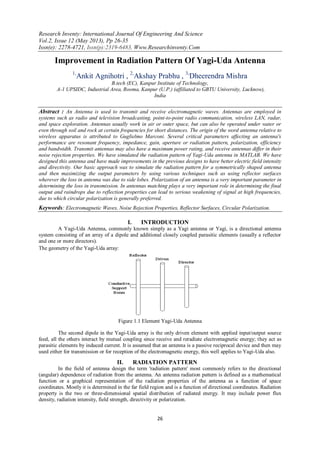
1. Research Inventy: International Journal Of Engineering And Science
Vol.2, Issue 12 (May 2013), Pp 26-35
Issn(e): 2278-4721, Issn(p):2319-6483, Www.Researchinventy.Com
26
Improvement in Radiation Pattern Of Yagi-Uda Antenna
1,
Ankit Agnihotri , 2,
Akshay Prabhu , 3,
Dheerendra Mishra
B.tech (EC), Kanpur Institute of Technology,
A-1 UPSIDC, Industrial Area, Rooma, Kanpur (U.P.) (affiliated to GBTU University, Lucknow),
India
Abstract : An Antenna is used to transmit and receive electromagnetic waves. Antennas are employed in
systems such as radio and television broadcasting, point-to-point radio communication, wireless LAN, radar,
and space exploration. Antennas usually work in air or outer space, but can also be operated under water or
even through soil and rock at certain frequencies for short distances. The origin of the word antenna relative to
wireless apparatus is attributed to Guglielmo Marconi. Several critical parameters affecting an antenna's
performance are resonant frequency, impedance, gain, aperture or radiation pattern, polarization, efficiency
and bandwidth. Transmit antennas may also have a maximum power rating, and receive antennas differ in their
noise rejection properties. We have simulated the radiation pattern of Yagi-Uda antenna in MATLAB. We have
designed this antenna and have made improvements in the previous designs to have better electric field intensity
and directivity. Our basic approach was to simulate the radiation pattern for a symmetrically shaped antenna
and then maximizing the output parameters by using various techniques such as using reflector surfaces
wherever the loss in antenna was due to side lobes. Polarization of an antenna is a very important parameter in
determining the loss in transmission. In antennas matching plays a very important role in determining the final
output and raindrops due to reflection properties can lead to serious weakening of signal at high frequencies,
due to which circular polarization is generally preferred.
Keywords: Electromagnetic Waves, Noise Rejection Properties, Reflector Surfaces, Circular Polarization.
I. INTRODUCTION
A Yagi-Uda Antenna, commonly known simply as a Yagi antenna or Yagi, is a directional antenna
system consisting of an array of a dipole and additional closely coupled parasitic elements (usually a reflector
and one or more directors).
The geometry of the Yagi-Uda array:
Figure 1.1 Element Yagi-Uda Antenna
The second dipole in the Yagi-Uda array is the only driven element with applied input/output source
feed, all the others interact by mutual coupling since receive and reradiate electromagnetic energy; they act as
parasitic elements by induced current. It is assumed that an antenna is a passive reciprocal device and then may
used either for transmission or for reception of the electromagnetic energy, this well applies to Yagi-Uda also.
II. RADIATION PATTERN
In the field of antenna design the term 'radiation pattern' most commonly refers to the directional
(angular) dependence of radiation from the antenna. An antenna radiation pattern is defined as a mathematical
function or a graphical representation of the radiation properties of the antenna as a function of space
coordinates. Mostly it is determined in the far field region and is a function of directional coordinates. Radiation
property is the two or three-dimensional spatial distribution of radiated energy. It may include power flux
density, radiation intensity, field strength, directivity or polarization.
2. Improvement In Radiation Pattern…
27
The spatial variation of electric or magnetic field is called field pattern.An isotropic radiator is a
theoretical point source of waves, which exhibits the same magnitude or properties when measured in all
directions. It has no preferred direction of radiation. It radiates uniformly in all directions over a sphere centered
on the source.
A directional antenna or beam antenna is an antenna, which radiates greater power in one, or more
directions allowing for increased performance on transmit and receive and reduced interference from unwanted
sources. Directional antennas like Yagi-Uda antennas provide increased performance over dipole antennas when
a greater concentration of radiation in a certain direction is desired. An omni directional antenna is an antenna
system, which radiates power uniformly in one plane with a directive pattern shape in a perpendicular plane.
Various parts of a radiation pattern are referred to as lobes, which may be either major, minor, side or back
lobes.
Figure 2.1 Parts Of Radiation Pattern
III. WORKING PRINCIPLE
The simplest or minimal Yagi-Uda antenna has at least two parasitic elements behind the Driven
Element (DE); the antenna with only one parasitic element as Reflector element (Ref) is generally called Yagi
antenna. This happens when the electrical length of the parasitic element is greater than the driven element.
Figure 3.1 Element Yagi (Reflector+Driven Element)
If the electrical length of the parasitic element is shorter than the driven element, the radiation pattern reversed
and the parasitic element became a Director (D) always in the two-elements of the Yagi antenna.
Figure 3.2 Element Yagi (Director+Driven Element)
Then the basic antenna, driven element with both Reflector and Director is called three elements Yagi-Uda, with
increased directivity or beam Gain.
3. Improvement In Radiation Pattern…
28
Figure 3.3 Element Yagi (Reflector+Driven Element+Director)
The reflector and directors in the Yagi-Uda antenna are so coupled into parasitic mode; they mutually
alter the radiation parameters of the driven element and for each element of the array. Then the physical
discovery consist in the increased gain by narrowing the beam width of the dipole alone in a very genially cheap
manner, by the means of simple metallic rod or tube conductors, then focus the electromagnetic energy into the
desired directions.
More than one parasitic element should be axially added in the front of the driven element and each one is called
director. As the reflector, the directors (D1…Dn) has not wired directly to the feed point. As the number of
director grows, it increases the directivity as the beam gain of the Yagi-Uda system array.In modern Yagi-Uda
design, the parasitic elements should be applied to increase the impedance bandwidth also, much more than a
single dipole alone, this is in advance to directional capability of the system to control pattern and impedance
with any possible desired combination. Yagi-Uda antennas are widely used in civilian, simple or professionals,
military applications also. Yagi-Uda design is used by lot of amateur radio enthusiast all over the world in
advance for any kind of wireless radio communication, television etc.
IV. MATHEMATICAL ANALYSIS
Figure 4.1 Yagi-Uda Antenna’s Set Up
The approach taken in formulating the method of solving the Yagi-Uda-type antenna problem is based
on an integral equation for the electric field of the array. The point-matching technique is then used to satisfy the
integra1 equation at discrete points on the axis of each element rather than attempting to satisfy this equation
everywhere on the surface of every element. Thus a system of linear algebraic equations is generated in term of
the complex coefficients in the Fourier series expansion of the currents on the elements. Inversion of the matrix
yields the value of these coefficients from which the current distributions, phase velocity, and far-field patterns
may readily be obtained. Experience has shown that if one chooses a sufficient, number of pointsat which to
match boundary conditions, then one can obtain solutions to problems, such as this one, theretofore not easily
solvable. In the case of linear elements it has been found that an efficient representation for the current on
element n is given by
In(z') =
M
m 1
Inm cos [(2m-1)πz/ln]
Inm represent the complex current coefficient of mode m on element n and In represents the corresponding length
on the n elements. This series of odd-ordered even modes is chosen such that the current goes to zero at the ends
of element n. This is a suitable approximation for elements whose diameter is small in terms of the Wavelength.
4. Improvement In Radiation Pattern…
29
The theory is based on Pocklington’s integral equation for total field generated be an electric current source
radiating in an unbounded space as given by the following mathematical analysis.
2/1
2/1
I(z') [(∂2
/∂z2
) + k2
] [(℮-jkR
)/R]dz' = j4πωε0Ez
t
Where
R = [(x-x')2
+ (y-y')2
+ (z-z')2
]1/2
Since we know that
(∂2
/∂z2
) [(℮-jkR
)/R] = (∂2
/∂z'2
) [(℮-jkR
)/R]
Putting this into the above equation, we get the reduced form of the Pocklington’s integral equation as:
2/1
2/1
I(z') [(℮-jkR
)/R]∂z'2
+ k2
2/1
2/1
I(z') [(℮-jkR
)/R]dz' = j4πωε0Ez
t
Now, we will concentrate on the integration of this reduced equation. Integrating the first term by parts where
u = I(z')
du = [dI(z')/dz']dz'
dv = (δ2
/ δz'2
) [(℮-jkR
)/R]∂z' = (δ/∂z') [(δ/∂z') (℮-jkR
)/R] dz'
v = (δ/∂z') (℮-jkR
)/R
Reduce it further to
2/1
2/1
(δ2
/ δz'2
) [(℮-jkR
)/R]∂z' = I(z') [(δ/∂z') (℮-jkR
)/R]|-1/2
1/2
-
2/1
2/1
[(δ/∂z') (℮-jkR
)/R](dI(z')/dz'
Since we require that the current at the ends of each wire vanish i.e. I z(z’= +l/2) = Iz (z’= -l/2) = 0, reduces
above equation to
2/1
2/1
(δ2
/ δz'2
) [(℮-jkR
)/R]dz' =
2/1
2/1
(δ/∂z') [(℮-jkR
)/R]dz'(dI(z')/dz'
Integrating by parts where
u = dI(z')/dz'
du = [d2
I(z')/dz'2
]dz'
dv = (δ/δz') [(℮-jkR
)/R]dz'
v = (℮-jkR
)/R
Reduce it to
2/1
2/1
(δ2
/ δz'2
) [(℮-jkR
)/R]dz' =[dI(z')/dz'] [(℮-jkR
)/R] |-1/2
1/2
+
2/1
2/1
(d2
/dz'2
) [(℮-jkR
)/R]dz'
When this is substituted for the first term, it is firther reduced to
[dI(z')/dz'] [(℮-jkR
)/R] |-1/2
1/2
+
2/1
2/1
[k2
I(z') + d2
I(z')/dz'] [(℮-jkR
)/R]dz' = j4πωε0Ez
t
For small diameter wires the current on each element can be approximated by a finite series of odd-ordered even
modes. Thus, the current on nth element can be written as a Fourier series expansion of following form
In(z') =
M
m 1
Inm cos [(2m-1)πz/ln]
Where Inm represents the complex current coefficient of mode m on element n and In represents the
corresponding length of the n element. Taking the Ist and IInd derivatives of above equation and substituting
them, results in
M
m 1
Inm {[(2m-1)π/In] sin[(2m-1)πz'n/ln] [(℮-jkR
)/R] |-ln/2
ln/2
+ [k2
- ((2m-1)2
π2
/ln
2
) .
2ln/
2ln/
cos[(2m-1)πz'n /ln]
((℮-jkR
)/R)dz'n} = j4πωε0Ez
t
5. Improvement In Radiation Pattern…
30
Since the cosine is an even function, above equation can be reduced by integrating over only 0<=z’<=l/2 to
M
m 1
Inm {(-1)m+1
[(2m-1)π/ln] G2(x,x',y,y'/z, ln) + [k2
- ((2m-1)2
π2
/ln
2
) .
2ln/
0
G2(x,x',y,y'/z,z'n)
cos[(2m-1)πz'n /ln]dz'n} = = j4πωε0Ez
t
Where
G2(x,x',y,y'/z,z'n) = (℮-jkRˍ
)/R_) + (℮-jkR ̟
)/R+)
R± = [(x-x')2
+ (y-y')2
+a2
+(z±z')2
]1/2
N = 1,2,3…,N
N = Total number of elements
Where
R± is the distance from the center of the each wire radius to center of any other wire.
The far-field pattern is given by
Eθ =
N
n 1
Eθn = -jωAθ
Where
Aθ =
N
n 1
A θn = (μ℮-jkr
/4Πr) sinθ
N
n 1
{ ℮jk(Xn sinθ cosɸ +Yn sinθ sinɸ)
M
m 1
Inm[sin(z+)/(z+) + sin(z-)/(z-) ]}ln/2
In the Matlab implementation, SINTEG function is for integration. Since integration is very difficult here, so we
have used weighted method i.e. Gaussian method which states “In numerical analysis, a quadrature rule is an
approximation of the definite integral of a function, usually stated as a weighted sum of function values at
specified points within the domain of integration.
V. FLOW CHART
The main concept of the code is based on Pocklington’s Integral Equation and is shown below:
Figure 5.1 Basic Flow Chart
6. Improvement In Radiation Pattern…
31
VI. NBS DESIGN
A government document has been published which provides extensive data of experimental
investigations carried out by National Bureau of Standards (NBS). We can obtain desired data from the
government document.
Figure 6.1 NBS Parameters for Yagi-Uda Antenna
Number of elements , N = 15
Radius of each element, a = 0.0085
Director length, l1 = l2 = 0.424, l3 = 0.420, l4 = 0.407, l5 = 0.403, l6 = 0.398, l7 = 0.394, l8 to l13 = 0.390
Reflector length, l14 = 0.475
Feeder (Driven element) length, l15 = 0.466
Spacing between directors = 0.308
Spacing between feeder & reflector = 0.2
The overall antenna length would be L = 4.2
The parameters (element lengths and spacing) are given in terms of wavelength.
The characteristic variables of the designed NBS antenna can be calculated and listed in the following table:
Directivity 14.2106
Front to back ratio of E-plane 12.0779
Front to back ratio of H-plane 12.0811
3dB beamwidth of E-plane 28.8770
3dB beamwidth of H-plane 30.5268
Table 6.1 Measured Parameters
VII. OPTIMIZATION TECHNIQUES
There are so many ways to optimize the directivity and other antenna parameters. First let’s take a look
at the most primitive method Trial and Error method.
Trial And Error Method
L1 = Length of reflector (159cm) = 0.4998λ
L2 = Length of driven element (149cm) = 0.4684 λ
L3 = Length of director (140cm) = 0.44.1 λ
S1 = Spacing between reflector and driven element (44cm) =0.1383 λ
S2 = Spacing between director and driven element (76cm) = 0.2389 λ
S3 = Spacing between directors (56cm) = 0.1760 λ
Radius = 0.7cm = 0.0022 λ
Frequency of operation = 94.3MHz
8. Improvement In Radiation Pattern…
33
S2 3dB
beamwidth
E-plane
(Degree)
3dB beamwidth
H-plane
(Degree)
Front-to-back
ratio E-plane
(dB)
Front-to-back
ratio H-plane
(dB)
Directivity
(dB)
L1=0.4998 0.2043 60.39 79.16 16.7544 16.7475 8.783
L2=0.4401 0.2200 59.60 77.21 14.5425 14.5362 8.978
L3=0.4401 0.2389 58.74 75.17 12.5439 12.5381 9.160
S1=0.1383 0.2515 58.23 74.01 11.4830 11.4773 9.246
R=0.0022 0.2672 57.68 72.74 10.3817 10.3763 9.308
Table 7.6: Varying Spacing Between Director And Driven Element
R 3dB
beamwidth
E-plane
(Degree)
3dB beamwidth
H-plane
(Degree)
Front-to-back
ratio E-plane
(dB)
Front-to-back
ratio H-plane
(dB)
Directivity
(dB)
L1=0.4998 0.0013 60.34 78.81 14.6641 14.6579 8.864
L2=0.4401 0.0016 59.77 77.47 13.8845 13.8785 8.978
L3=0.4401 0.0022 58.74 75.17 12.5439 12.5381 9.160
S1=0.1383 0.0031 57.41 72.32 10.9441 10.9385 9.351
S2=0.2389 0.0041 56.12 69.67 9.5508 9.5454 9.476
Table 7.7: Varying Radius of Each Element
For M = 3 & N = 12
S3 3dB
beamwidth
E-plane
(Degree)
3dB beamwidth
H-plane
(Degree)
Front-to-back
ratio E-plane
(dB)
Front-to-back
ratio H-plane
(dB)
Directivity
(dB)
L1=0.499
8
0.1414 33.47 36.10 5.8692 5.8591 8.483
L2=0.440
1
0.1572 30.75 32.45 8.6325 8.6293 8.609
L3=0.440
1
0.1760 32.45 34.81 16.9353 16.9205 9.993
S1=0.138
3
0.1886 29.94 31.60 8.3003 8.2872 9.829
S2=0.238
9
0.2043 29.19 30.66 9.1289 9.1181 10.801
R=0.002
2
Table 7.8: Varying Spacing Between Directors
The above results show the variation of antenna parameters on changing the element measures.Genetic
Algorithm Based Automated Antenna Optimization System: Yagi-uda antennas are known to be difficult to
design and optimize due to their sensitivity at high gain and the inclusion of numerous parasitic elements. A
genetic algorithm based automated antenna optimization system that uses a fixed Yagi-uda antenna topology
and a byte encoded antenna representation, is presented here. The fitness calculation allows the implicit
relationship between power gain and sidelobe/backlobe loss to emerge naturally, a technique that is less
complex than previous approaches. The genetic operator used is also simple. The result include Yagi-Uda
antenna that have excellent bandwidth and gain properties with very good impedance characteristics. Results
exceeded previous Yagi-Uda antenna produced via evolution algorithms by at least 7.8% in mainlobe gain.
Figure 7.1: Genetic Algorithm Based Antenna
9. Improvement In Radiation Pattern…
34
This scheme comprises of 14 elements, each one encoding a length and spacing value. Each floating
point value was encoded as three bytes, yielding resolution of 1/224 per value. The first pair of values encoded
the reflector element, the second pair encoded the driven element and the remaining 12 pairs encoded the
directors. Our point crossover was used with cut points allowed between bytes. Mutation was applied on the
individual bytes. Radius values were constrained to 2, 3, 4 or 6mm. All the elements within given individual
were assigned the same radius value. Element lengths were constrained to be symmetrical around the x-axis and
between 0 and 1.5 . Elements having zero length were removed from the antenna; as a consequence, a
constructed antenna could have less than 14 elements. Spacing between adjacent elements (along the z-axis) was
constrained to be between 0.05 and 0.75 . The wavelength was1.195 and frequency of 235MHz.
VIII. CONCLUSION
The properties of a receiver mode Yagi are relatively uncritical. The bandwidth and VSWR
performance matters less than the gain of the antenna and its discrimination against unwanted signals. However,
for a transmit Yagi such as is commonly used by Hams and short-wave broadcasters, the accepted power
depends critically on getting a good match to the feed. This will vary across the band and is susceptible to the
variations in the local environment and geometry distortions.The lore of the Yagi designer has it that the gain of
a yagi is governed more by the overall boom length than by the number of elements. For an HF Yagi, the boom
length can be a critical factor, and the Ham is usually seeking to optimize the forward gain, the front-to-back
ratio and the construction techniques required. Yagi si having thick rod elements (in terms of a wavelength) is
better-behaved than those made from thin wires.
The gain of a Yagi-Uda is only moderate, but for the frequency range given above it is cheap and
relatively simple to build. It is reasonably tolerant to the variations in construction and indeed many Yagi-Uda
designs have been arrived at the cut and try empirical methods.
This is why antenna design is often seen as a black art. With proper numerical simulation, useful
improvements have been made to the empirical design. Tradeoffs may be made between the various factors such
as, bandwidth, impedance, front-to-back ratio, gain, sidelobe performance and ease of mounting. A vertically
polarized Yagi-Uda often is mounted on the top of a vertical conducting mast which, being in the near field and
also polarized matched, will modify the electrical properties. There is less of a problem with mounting a
horizontally polarized Yagi-Uda antenna.
For moderately long Yagis with several directors, the reflector spacing and size has a little effect on the
forward gain, providing that there is a reflector, but being close to the driving element it has a strong effect on
the front-to-back ratio and on the driving point impedance of the antenna. The driving element has of course a
big effect on the impedance of the structure and it can be tuned to make this impedance nearly real. The
directors form the majority of the travelling wave structure.The gain of a Yagi antenna is governed mainly by
the number of elements in the particular RF antenna. However the spacing between the elements also has an
effect. As the overall performance of the RF antenna has so many inter-related variables, many early design
were not able to realize their full performance. Today computer programs are used to optimize RF antenna
design before they are manufactured and as a result the performance of antenna has improved.
Number Of Elements Approximate Anticipated Gain
(dB Over Dipole)
2 5
3 7.5
4 8.5
5 9.5
6 10.5
7 11.5
Table 8.1: Parameters
The front-to-back ratio is important in circumstances where interference or coverage in the reverse direction
needs to be minimized. Unfortunately the conditions within the antenna mean that optimization has to be
undertaken for either.Front-to-back ratio or the maximum forward gain, conditions for both features do not
coincide, but the front-to-back ratio can normally be maximized for a small degradation of the forward gain.
10. Improvement In Radiation Pattern…
35
REFERENCES
[1] Antenna Theory , Analysis And Design By Constantine A. Balanis
[2] Antenna Engineering Handbook ( A.W. Love And T.S. Bird)
[3] R.E. Collin, “Antennas And Radio Wave Propagation”
[4] Robert S. Elliot, “Antenna Theory And Design”
[5] Antenna Theory And Design By Stutzman Thiele
[6] Modern Antenna Design By Thomas A. Milligan
[7] Antenna And EM Modeling With Matlab By Sergey N. Makarov
[8] Antenna Design And Visualization Using Matlab By Atef Z. Elsherbeni And Matthew J. Inman
[9] IEEE Antennas And Propagation Magazine, Vol. 46, No. 5, October 2004.
[10] Antennas And Propagation, IEEE Transactions On [Legacy, Pre - 1988] Volume 27, Issue 2, Mar 1979 Page(S):267 – 270