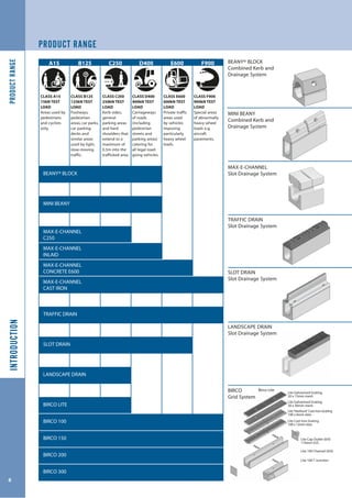
D R A I N A G E D E S I G N G U I D E
CI/SfB
(52)
August 2004
www.marshalls.co.uk/drainage
INTRODUCTION
Almost all impermeable surfaces require some form
of surface water drainage. Highways, service and
storage facilities, car parks and pedestrian areas are best
accommodated by either combined kerb and drainage or
linear drainage systems bearing in mind location, efficiency,
traffic loading, maintenance and aesthetics.
Marshalls is one of the leading suppliers of drainage
products and offers a comprehensive range of surface water
drainage systems to cater for all applications. Marshalls also
understands the design principles of Sustainable Urban
Drainage Systems and particularly how designers can
achieve sustainable drainage solutions using linear drainage
systems or impermeable pavement design or an appropriate
combination of both systems as the project requires.
Two combined kerb and drainage systems are available - the
original, well established Beany Block and now the recent
addition of a smaller version, appropriately named
Mini Beany. These are complemented by the large capacity
Max-E-Channel and Birco Linear drainage systems.
This comprehensive range of drainage options allows the
designer to cater for:
• Long lengths of highway (several kilometres
depending on carriageway width and gradient)
• Large or small paved areas
• High storm water intensities
• Flat or steep gradients
• Heavy vehicular loading
• Shallow depth construction
• Temporary storm water storage
• Appropriate aesthetic finishes
• Minimal maintenance
The range of linear drainage systems is further enhanced by
new innovative products such as Traffic Drain, Landscape
Drain, Max-E-Channel inlaid covers and Slot Drain.
Most importantly, with Marshalls, the optimum economical
drainage design can be readily achieved.
All Marshalls systems comply with the requirements,
of the appropriate standard; BS EN 9001, the Highway
Agency’s Specification for Highway Works together with the
requirements of British Standard, BS EN 1433:2002.
BS EN 1433:2002
Marshalls’policy is to manufacture products that, as a
minimum requirement, comply with the relevant European,
British or Company Standard as appropriate.
Following the publication of any European Standard the
government recognises that there is a period whereby
manufacturers need to realign their product offer, quality
control and in many cases the manufacturing operations.
It is Marshalls' intention that the manufacture of all its linear
drainage products complies with BS EN 1433:2002 within
the required time frame.The load classification system
documented in this Standard is referenced throughout this
Design Guide. Details of product specific requirements are
published in the product data sheets.
DESIGN GUIDANCE AND CAD
Marshalls Computer Aided Design service can be called
upon by specifiers and contractors alike in relation to the
detailing of Marshalls Drainage products.
The drawings are created in consultation with the
Design Team. Contact drainage@marshalls.co.uk
CONTENTS
3
INTRODUCTION
CONTENTS ..................................................................................................3
PRODUCT RANGE ....................................................................................6
THE CASE FOR LINEAR DRAINAGE .....................................................8
COST COMPARISON ................................................................................9
SELECTION PROCESS ............................................................................10
DESIGN PRINCIPLES ..............................................................................14
GENERAL CONSTRUCTION .................................................................18
CAST IRON ................................................................................................18
DESIGN SERVICE .....................................................................................19
FURTHER INFORMATION .....................................................................19
REFERENCES & FURTHER READING .................................................20
BEANY® BLOCK
CONTENTS ................................................................................................21
COMPONENTS ........................................................................................22
HYDRAULIC DATA ..................................................................................24
STANDARD DETAILS .............................................................................27
CONSTRUCTION .....................................................................................36
SPECIFICATION .......................................................................................39
ITEM CODES .............................................................................................40
MINI BEANY
CONTENTS ................................................................................................41
COMPONENTS ........................................................................................42
HYDRAULIC DATA ..................................................................................44
STANDARD DETAILS .............................................................................46
CONSTRUCTION .....................................................................................54
SPECIFICATION .......................................................................................57
ITEM CODES .............................................................................................58
MAX-E-CHANNEL
CONTENTS ................................................................................................59
COMPONENTS ........................................................................................60
HYDRAULIC DATA ..................................................................................62
STANDARD DETAILS .............................................................................65
CONSTRUCTION .....................................................................................70
SPECIFICATION .......................................................................................71
ITEM CODES .............................................................................................72
TRAFFIC DRAIN
CONTENTS ................................................................................................73
COMPONENTS ........................................................................................74
HYDRAULIC DATA ..................................................................................76
STANDARD DETAILS .............................................................................78
CONSTRUCTION .....................................................................................84
SPECIFICATION .......................................................................................85
ITEM CODES .............................................................................................86
SLOT DRAIN
CONTENTS ................................................................................................87
COMPONENTS ........................................................................................88
HYDRAULIC DATA ..................................................................................89
STANDARD DETAILS .............................................................................90
CONSTRUCTION .....................................................................................91
SPECIFICATION .......................................................................................92
ITEM CODES .............................................................................................92
LANDSCAPE DRAIN
CONTENTS ................................................................................................93
COMPONENTS ........................................................................................94
HYDRAULIC DATA ..................................................................................96
STANDARD DETAILS .............................................................................97
CONSTRUCTION .....................................................................................98
SPECIFICATION ......................................................................................99
ITEM CODES ..........................................................................................100
BIRCO
CONTENTS .............................................................................................101
COMPONENTS .....................................................................................102
HYDRAULIC DATA ...............................................................................109
STANDARD DETAILS ..........................................................................112
CONSTRUCTION ..................................................................................116
SPECIFICATION ....................................................................................117
ITEM CODES ..........................................................................................118
CONTENTS
STATEMENT
Marshalls plc is the UK’s leading manufacturer of superior
concrete, clay and natural stone products which transform
landscapes and redefine the built environment. With more
than 120 years experience, Marshalls’ expertise in materials
sourcing, manufacturing, distribution, technical advice and
customer service is respected within the industry, making
us the preferred supplier for prestigious projects including
Trafalgar Square, London; Trafford Centre, Manchester and
the Falkirk Wheel, Scotland.
As a truly customer focused organisation, Marshalls’
commitment to delivering and exceeding client satisfaction
throughout the supply chain is our priority. Product
innovation is at the heart of our business, ensuring
our customers have access to a comprehensive and
enviable product portfolio to complete their landscaping
requirements, from paving, block paving, kerb and drainage
to street furniture. Injecting innovation into new product
development and investing in revolutionary manufacturing
techniques cements Marshalls’ market leading position.
Our vision, to deliver the products customers want, on time,
every time, is supported by Marshalls’ teams of design,
technical and customer service experts, ensuring Marshalls
can service clients’ needs from project and design conception
right the way through to installation and maintenance. As a
major plc, Marshalls was recently rated as the UK’s 37th most
admired company, and as a group its expert companies have
become the landscape sector’s benchmark for excellence.
The company is committed to quality in everything it does,
offering its customers honesty, integrity and experience for
total peace of mind.
The new Marshalls Drainage Design Guide builds upon its well
received predecessor.
This new version has therefore added to the features and
benefits our colleagues in the building and construction
industry have identified.
Most importantly, this new Design Guide is vitally linked
to, and supported by, a continually developing website
which adds further functions and features to the vast pool of
information Marshalls provides for users.
Suffice to say Marshalls continues to carry the most
comprehensive range of quality landscape and building
materials available to the construction industry.
ENVIRONMENTAL POLICY
Marshalls is committed to achieving the highest standards of
environmental performance and continually aims to prevent
pollution and minimise the impact of its operations. The
Group’s aim is that no lasting environmental damage occurs
as a result of its activities, and policies are being implemented
to ensure that all of its operations meet or exceed the
requirements of legislation and applicable best practice.
Marshalls regards compliance with relevant environmental
laws, and the adoption of responsible standards where no
legislation exists, as an integral part of its business strategy
and is committed to considering the environmental impacts
associated with its products throughout their life-cycle.
Marshalls has committed to monitor its environmental
performance in line with Construction Products Association
requirements, and to set objectives and targets to improve
its impacts in key areas. These will be reviewed on at least an
annual basis to ensure continual improvement.
Marshalls will continue to raise environmental awareness
within the Group through the development and training of
its employees, and will communicate openly and consult
with customers, suppliers and other stakeholders on relevant
environmental matters.
Marshalls strives to conserve natural habitats and create
additional areas of wildlife value wherever possible. The
Group also recognises the need for sympathetic restoration
and after use of quarry sites, and considers the character of
the local environment and the concerns of the community
when planning such matters.
QUALITY POLICY
Marshalls aims to produce and supply to all clients excellent
building materials for all applications. It is the intention to
achieve this by offering;
• Products that meet all standard requirements
• First class customer service
• Complete and on-time deliveries
• Free technical advice
Marshalls is committed to continual review and improvement
of processes, products and services and places its customers
first in considerations. These aims will be achieved by
continual training and communication to all personnel of key
business objectives.
Objectives are set at Group level and instigated by Divisional
and Regional management within annual Business Plans.
4
CONTENTSINTRODUCTION
5
INTRODUCTION
CONTENTS ...................................................................3
PRODUCT RANGE .....................................................6
THE CASE FOR LINEAR DRAINAGE ......................8
COST COMPARISON .................................................9
SELECTION PROCESS .............................................10
DESIGN PRINCIPLES ...............................................14
GENERAL CONSTRUCTION ..................................18
CAST IRON .................................................................18
DESIGN SERVICES ...................................................19
FURTHER INFORMATION ......................................19
REFERENCES & FURTHER READING ..................20
PRODUCTRANGEINTRODUCTION
6
PRODUCT RANGE
A15 B125 C250 D400 E600 F900
CLASS A15
15kN TEST
LOAD
Areas used by
pedestrians
and cyclists
only.
CLASS B125
125kN TEST
LOAD
Footways,
pedestrian
areas, car parks,
car parking
decks and
similar areas
used by light,
slow-moving
traffic.
CLASS C250
250kN TEST
LOAD
Kerb-sides,
general
parking areas
and hard
shoulders that
extend to a
maximum of
0.5m into the
trafficked area.
CLASS D400
400kN TEST
LOAD
Carriageways
of roads
(including
pedestrian
streets and
parking areas)
catering for
all legal road-
going vehicles.
CLASS E600
600kN TEST
LOAD
Private traffic
areas used
by vehicles
imposing
particularly
heavy wheel
loads.
CLASS F900
900kN TEST
LOAD
Special areas
of abnormally
heavy wheel
loads e.g.
aircraft
pavements.
BEANY® BLOCK
MINI BEANY
MAX-E-CHANNEL
C250
TRAFFIC DRAIN
SLOT DRAIN
LANDSCAPE DRAIN
BIRCO LITE
BIRCO 100
BIRCO 150
BIRCO 200
BIRCO 300
MAX-E-CHANNEL
INLAID
MAX-E-CHANNEL
CONCRETE E600
MAX-E-CHANNEL
CAST IRON
BEANY® BLOCK
Combined Kerb and
Drainage System
MINI BEANY
Combined Kerb and
Drainage System
MAX-E-CHANNEL
Slot Drainage System
TRAFFIC DRAIN
Slot Drainage System
SLOT DRAIN
Slot Drainage System
LANDSCAPE DRAIN
Slot Drainage System
BIRCO
Grid System
Lite Cap Outlet (0/0)
110mm O.D.
Lite 100 Channel (0/0)
Lite 100 T Junction
Lite Galvanised Grating
30 x 15mm mesh
Lite Galvanised Grating
30 x 30mm mesh
Lite 'Heelsure' Cast Iron Grating
100 x 6mm slots
Lite Cast Iron Grating
100 x 12mm slots
Birco Lite
PRODUCTRANGEINTRODUCTION
7
Base 205 Base 295 Base 365 Base 630HB Straight
Backed
HB Straight
Backed Low
Hole
HB Symmetrical Symmetrical
Low Hole
45º Splayed
HB Top Block 45O
Splayed Top
Base 205 Base 295 Base 365 Base 630Inlaid UnitCast Iron
F900
Reinforced
Concrete E600
Concrete
C250
Base 185 Base 235 Base 285 Base 335 Base 385Top Unit
Cast Iron
F900
Slot Drain 105
0/0 5/0 10/0 15/0 20/0
Slot Drain 90
0/0 5/0 10/0 15/0 20/0Top Unit
Base 185 Base 235 Base 285 Base 335 Base 385
Birco 100 100 Galvanised Grating
20 x 30mm mesh
100 Galvanised Grating
30 x 15mm mesh
100 Galvanised Grating
30 x 30mm mesh
100 'Heelsure' Cast Iron Grating
100 x 6mm slots
100 Cast Iron Grating
100 x 12mm slots
100 Cap Outlet
106mm O.D.
100 Channel
100 T
Junction
Channel
150 Galvanised Grating
20 x 30mm mesh
150 Cast Iron Grating
150 x 12mm slots
150 Cap Outlet (0/0)
158mm O.D.
150 Channel (0/0)
150 T Junction
Channel (0/0)
200 Cap Outlet (0/0)
198mm O.D.
200 Galvanised Grating
20 x 30mm mesh
200 Cast Iron Grating
200 x 18mm slots
200
Channel
(0/0)
200 T
Junction
Channel
(0/0)
300 Cast Iron
Grating
125 x 20mm
slots
300 Channel
300 Cap Outlet
308mm O.D.
Birco 150 Birco 200 Birco 300
Birco 100
THECASEFORLINEARDRAINAGEINTRODUCTION
8
THE CASE FOR LINEAR DRAINAGE
INTRODUCTION
The growing demand for more cost-effective and less
complicated drainage systems has led to modern linear
drainage becoming the preferred choice amongst specifiers
and contractors alike.
Marshalls’ unique linear drainage systems combine the
clear-cut advantages of linear drainage over traditional point
drainage, with the benefits of a high quality, robust precast
concrete product.
SURFACE WATER INTERCEPTION
• More efficient at intercepting running water
• Ponding is reduced or eliminated as is streaming water
across a site
SHALLOW DEPTH OF CONSTRUCTION
• Inherently shallow construction required
• Savings due to reduced excavation
• Reduces construction time, offering further savings
• Less conflict with existing underground services
• Reduced quantities of spoil to be disposed of
EASE OF DESIGN
Performs more efficiently with just the use of concrete
channels, grates, outfalls and reduced amounts of pipework.
• Only requires shallow depth construction
• Limited number of components required
• Does not require complex crossfalls to be incorporated
• Design of crossfalls and longitudinal falls of adjacent hard
landscaping is straightforward
• Improved end user performance
EASE OF INSTALLATION
• Channel line and level can be set out with ease
• Crossfalls are less complex to set out or construct
compared with point drainage
• Expensive construction time saved due to shallow
construction
• On-site errors are easier to avoid
• Unlike other options, Marshalls’ systems do not require
temporary ballast (e.g. sand) during installation
• Inherently strong and robust precast concrete reduces
on-site damage
SIGNIFICANT COST SAVINGS BY REDUCING CARRIER PIPES
• Many schemes can utilise the inherent ability of a channel
or combined kerb and drainage system to act not just
as the traditional gully in point drainage, but also as the
carrier pipe in storing and transporting surface water.
• Any carrier pipes will be at a shallower depth with resultant
cost savings
• Fewer expensive manholes required
• Less spoil to be removed from site
• Improved health and safety on site through reduced need
for deep excavation work
Fig. 2 Typical equivalent linear drainage system
STORAGE OF SURFACE WATER
Linear drainage can utilise the storage capability of its
channels to good effect where there are limitations placed
on the total outflow of the scheme. This temporary storage
facility has been utilised to:
• Attenuate peak flows
• Avoid or reduce costs of balancing ponds or reservoirs
• Reduce pipework sizes at outfalls
REDUCED MAINTENANCE
• Easier and less costly to maintain than other forms of
surface water drainage systems
• Easy to access along the whole length of the linear
drainage system via removable gratings or regular access
points
• Blockages will not completely disrupt the whole system
and can be dealt with easily
• Inherently strong and robust precast concrete systems
resistant to the effects of freeze thaw and de-icing salts
AESTHETICS
• Wide choice of decorative metal gratings or textured
and coloured top blocks to enhance the aesthetics of a
scheme
• Straight lines of linear drainage can be incorporated into
the overall design
CONTROL OF SPILLAGE
• Allows total control of unwanted liquids in an emergency
END USER COMFORT
• Eliminates false falls and consequent ‘roller coaster’ effect
for vehicular traffic associated with point drainage
• Level surface offers greater comfort to pedestrians
Fig. 1 Typical point drainage system, illustrating the need for complex crossfalls
with attendant implications for design, installation and cost
£5,482TOTAL
£6,696
£11,950
£28,100
TOTAL
COSTCOMPARISONINTRODUCTION
9
NOTE: All rates taken from recent tender documents
POINT DRAINAGE VS BIRCO
Example: A service yard with an area of 100m x 60m with
a crossfall of 1 in 60 to suit either point drainage or linear
drainage located centrally as indicated. No longitudinal fall is
to be allowed.
POINT DRAINAGE
COST COMPARISON
DESCRIPTION QUANTITY UNIT RATE(£) TOTAL(£)
Gullies 32 No. 150 4,800
225mm dia.
Pipework
180 m 50 9,000
150mm dia.
Pipework
340 m 35 11,900
Manholes 4 No. 600 2,400
COST SAVING USING BIRCO, (RATHER THAN POINT
DRAINAGE) = 60%
TOTAL
DESCRIPTION QUANTITY UNIT RATE(£) TOTAL(£)
Birco 100 100 m 60 6,000
225mm dia.
Pipework
85 m 50 4,250
Outfall Units 2 m 250 500
Manholes 2 No. 600 1,200
BIRCO LINEAR DRAINAGE
Example: A supermarket car park with an area of 100m x 60m
with a crossfall of 1 in 60 to suit either point drainage or linear
drainage located centrally. Longitudinal fall is to be 1 in 200.
POINT DRAINAGE COST BREAKDOWN
MAX-E-CHANNEL DRAINAGE COST BREAKDOWN
POINT DRAINAGE V BEANY® BLOCK
Example: 100-metre length of the road with crossfall and
gullies at 15-metre spacing
DESCRIPTION QUANTITY UNIT RATE(£) TOTAL(£)
Kerbs
(125 x 255mm)
100 m 9.25 925
225 dia. S.W.D
(Depth to invert
1.5m)
100 No. 43.50 4,356
Gullies 2 No. 150 300
Gullies
Connection
20 No. 22 440
Manholes*
(Depth not
exceeding 2m)
0.67 No. 650 435
Footway** 20 M2
12 240
TOTAL
* Manholes @ 150m intervals
** Savings of 20m2
(0.2 x 100) of footpath due to Beany®
being wider than kerb
DESCRIPTION QUANTITY UNIT RATE(£) TOTAL(£)
Beany® Block
(Standard top
and base)
100 m 52 5,200
Outfall Type 1 1 No. 200 200
Access Cover 1 No. 82 82
BEANY® BLOCK COST BREAKDOWN
COST SAVING USING BEANY® BLOCK, (RATHER THAN POINT
DRAINAGE) = 18%
POINT DRAINAGE V MAX-E-CHANNEL
£28,100
DESCRIPTION QUANTITY UNIT RATE(£) TOTAL(£)
Gullies 32 No. 150 4,800
225mm dia.
Pipework
180 m 50 9,000
150mm dia.
Pipework
340 m 35 11,900
Manholes 4 No. 600 2,400
TOTAL
£10,500
DESCRIPTION QUANTITY UNIT RATE(£) TOTAL(£)
Max-E-Channel 100 m 100* 10,000
Outfall Units 2 No. 250 500
TOTAL
* Fully installed cost per metre assuming plain concrete top
unit and Base 365
COST SAVING USING MAX-E-CHANNEL , (RATHER THAN
POINT DRAINAGE) = 62%
CONVENTIONAL DRAINAGE COST BREAKDOWN USING
RECENT FIGURES
LINEAR DRAINAGE PRODUCT SELECTION PROCEDURE
The following pages describe the procedure for choosing
the most appropriate Marshalls linear drainage system for a
particular application.
Marshalls’ comprehensive range of drainage systems can be
split into three categories;
1. Combined Kerb and Drainage systems specifically
designed for kerbside use;
• Beany Block
• Mini Beany
2. Slot Drainage Systems designed primarily (though
not exclusively) for non-kerbside use;
• Max-E-Channel
• Marshalls Slot Drain
• Traffic Drain
• Landscape Drain
3. Grid Drainage Systems designed primarily (though
not exclusively) for non-kerbside use;
• Birco
The position of outfall, the area to be drained, topography
and rainfall intensity will each affect the final decision as to
which is the most appropriate system. However, there are two
fundamental factors which, more than any other, determine
which system is most appropriate;
• Location( i.e.kerbside or non-kerbside)
• Capacity
Beany Block*
Mini Beany*
Max-E-Channel
Birco 200 & 300
Birco Lite/Birco
100/Birco 150/
Landscape Drain/
Traffic Drain/
Slot Drain
Combined
Kerb & Drainage
Systems
Capacity
Kerbside
Non-kerbside/
Channel
Location
Linear
Drainage
* Slot Drainage and Grid System can also be used in kerbside
locations. Where this is the case follow the design procedure for non-
kerbside/ channel drainage
medium
high
medium
high
SELECTIONPROCESSINTRODUCTION
10
SELECTION PROCESS
Capacity
Slot Drainage &
Grid Systems
Fig. 3 General Principles for Selecting the Appropriate System
SELECTIONPROCESSINTRODUCTION
11
COMBINED KERB AND DRAINAGE SYSTEMS
Marshalls manufactures two types of combined kerb
and drainage systems specifically designed for kerbside
applications;
• Beany Block
• Mini Beany
SELECTION PROCEDURE
The key deciding factor as to which combined kerb and
drainage system to specify will often be flow capacity.
The following procedure and graph can be used to determine
which of the two Marshalls systems is most appropriate:
Step 1 Determine gradient of the system
Step 2 Determine peak flow in the system
Step 3 Refer to graph Fig. 4 (below) to determine which is
the most appropriate system
EXAMPLE 1
For a combined kerb and drainage system, with a gradient of
1 in 100, where the calculated peak discharged is 54l/s. Fig. 3
shows that Mini Beany has a capacity of 66 l/s at a gradient of
1 in 100. Refer to the Mini Beany section, page 41, to
determine which of the Mini Beany systems to specify.
Fig. 4 Mini Beany and Beany Block flow capacities
EXAMPLE 2
Alternatively, for a combined kerb and drainage system, with
a gradient of 1 in 500 and a peak discharge of 175 l/s,
then Fig. 4 indicates that Beany Block will be required. Refer
to the Beany Block section, page 21, to determine the
appropriate system.
CHANNEL DRAINAGE SYSTEMS
Five channel linear drainage systems are available from
Marshalls, designed primarily (though not exclusively) for
non-kerbside applications;
• Max-E-Channel High Capacity Linear Drainage System
• Birco Linear Drainage System
• Landscape Drain
• Slot Drain
• Traffic Drain
SELECTION PROCEDURE
The choice of channel drainage system will often be
determined by site parameters, such as size of area to be
drained, existing levels and length of drainage runs. The
following steps should be followed to establish the most
appropriate Marshalls channel.
Step 1
Determine the location of the channel drainage system
within the drained area.
Step 2
Determine the length of run of the channel.
Step 3
If the channel length is approx 60m, refer to Birco 100, Birco
Lite or Landscape Drain. Refer to page 101 (See note 1).
Step 4
If the channel length is well in excess of 60m, refer
to the Max-E-Channel range page 59 and Birco 300
page 101. Choose either a large capacity system with few
outfalls or a medium capacity system with more outfalls
(See note 2).
Step 5
Determine the load classification of the channel system’s
application and specify the appropriate grating or top unit
(See note 3).
IN ADDITION TO THE ABOVE, THE FOLLOWING FACTORS
SHOULD ALSO BE CONSIDERED:
LOCATION OF EXISTING MAIN DRAINAGE
• If the location of the existing drainage system is fixed, it
will determine outfall locations and optimum design of
the linear drainage system may not be possible
OUTFALL PIPE CAPACITY
• Whatever linear drainage system is used, the outfall
pipework must be designed to accommodate the peak
discharge from the system
Fig 5. Summary of General Principles for Selecting an Appropriate Marshalls’ Channel System
SELECTIONPROCESSINTRODUCTION
12
SELECTION PROCESS
Location
Determine
length of
run channel
Birco Lite,
100, 150, 200
Landscape
Drain Traffic
Drain, Slot
Drain
See Note 1
Approx
60m
Well over
60m
Medium capacity
systems with
multiple Outfalls
See Note 2
High capacity
systems with
few Outfalls
See Note 3
Birco Lite,
100, 150,
Landscape
Drain
Slot Drain
Max-E-Channel
or
Birco 200, 300
Determine appropriate
grating load
classification
See Note 3
Determine appropriate
grating load
classification
See Note 3
Determine appropriate
grating load
classification
See Note 3
SELECTIONPROCESSINTRODUCTION
13
NOTES
1) Generally, where the linear drainage channel length is
in the order of 60m, one centrally located outfall will be
sufficient and a medium capacity system such as Birco
Lite, Landscape Drain or Birco 100 can be used.
Example
A relatively small paved area of dimensions 50 x 50m can
be easily drained by a 100mm wide channel system such
as Birco Lite, Landscape Drain or Birco 100. One centrally
located outfall to suit the existing main drainage system
will be sufficient.
2) Where linear drainage channel runs are well in excess of
60m, say 200m, then there is a choice of 2 options;
Option 1 - a high capacity system (Max-E-Channel or Birco
300) with few outfalls or, alternatively;
Option 2 - a medium capacity system (eg Birco 100) with
multiple outfalls
Example
For a paved area of dimensions 200 x 150m, then the
options are as follows;
Option 1
This example shows typically two Birco Lite, 100 or
Landscape Drain runs utilising in-built fall channels, with
four outfalls discharging into a carrier pipe system. This
is a highly cost-effective solution and would result in
considerable savings compared to an alternative point
drainage solution.
3) The loading classifications, as defined in BS EN 1433: 2002
‘Drainage channels for vehicular and pedestrian areas
- classification, design and testing requirements, marking
and quality control, are as follows;
Class A15 Areas which can only be used by
pedestrians and pedal cyclists
Class B125 Footways, pedestrian areas and compatible
areas, private car parks or parking decks
Class C250 Kerbside and non-trafficked areas of hard
shoulder that extend to a maximum of
0.5m into the trafficked area
Class D400 Carriageways of roads, hard shoulders and
parking areas for all vehicles
Class E600 Areas subject to high wheel loads e.g. ports
and docksides
Class F900 Areas subject to especially high wheel
loads e.g. aircraft pavements
This example shows Marshalls’ Max-E-Channel or Birco
300 draining the area with only one outfall at the end
of the channel run. Less carrier pipes are used, resulting
in even greater cost savings. There will also be less
excavation with this design.
Option 2
Fig. 6 High Capacity System with Few Outfalls
Fig.7 Medium Capacity System with Multiple Outfalls
INTRODUCTION
The basis of hydraulic design of any linear drainage system
is fundamentally like any other engineering analysis; an
assessment is made of the required performance level that
the element has to achieve and this is compared to the
element’s ability to accommodate this. In the case of linear
drainage, how much water (peak run-off) will be flowing
down the channel compared to the maximum stated flow
capacity of the channel for the given conditions without
causing any problems such as flooding.
There are therefore two elements to any linear drainage
design; a determination of the peak run-off or maximum
flow along and out of the channel and a determination of the
system’s maximum capacity.
PEAK RUN-OFF
The determination of peak run-off will depend upon many
considerations including;
• Size and location of the drained area
• Use and application of the drained area
• Chosen or calculated rainfall intensity
Whilst several methods of calculating the peak storm water
run-off exist, there are two which [Marshalls recommend]
should be considered when designing linear drainage
systems;
• The Simple Area Run-Off Method
• The Modified Rational Method (often referred to as
The Wallingford Procedure)
THE SIMPLE AREA RUN-OFF METHOD
In the Simple Area Run-Off Method, it is assumed that the
whole of the drained area contributes to the peak flow, that
the rainfall intensity is uniform over the whole area and
additionally that a value for the rainfall intensity is actually
assumed. Therefore the assumed value for rainfall intensity
is directly proportional to the peak run-off. A balance is often
made between cost and the level of performance required
but it is generally accepted that this method will yield
conservative results.
The peak run-off formula used in this method is:-
Q = A x i/3600, where
Q is the peak storm water run-off (in litres per second)
A is the drained area (in square metres)
“i” is the rainfall intensity (in millimetres per hour)
Some typical values assumed for rainfall intensity are given
below. Engineers and designers must choose carefully and
give due consideration to the performance level required;
• 75mm/hr (0.021 l/m²/s) Areas where the consequences
of flooding is serious such as where roof drainage [or
entrances to buildings] is involved
• 50mm/hr (0.014 l/m²/s) Car parks, pedestrian areas, roads
or highways
• 40mm/hr (0.011 l/m²/s) Service yards
• 30mm/hr (0.008 l/m²/s) Large storage areas such as ports
In addition, this method of peak run-off determination should
be limited to use when designing relatively small drained
areas (less than 10,000m²) and when designing relatively
short runs of linear drainage (less than 200m).
THE MODIFIED RATIONAL METHOD
The Modified Rational Method (often referred to as
The Wallingford Procedure) is considered more accurate for
larger schemes with longer drainage runs. Whilst the method
generally assumes that the whole drained area contributes
to the peak run-off, it uses typical storm profiles based upon
actual data and takes into account actual geographical
rainfall variations. In this way, the critical rainfall intensity for
a given set of parameters and conditions can be calculated.
The only decision that a designer makes is to choose a storm
return period. Again several factors will influence this choice
but periods of between 1 in one year to 1 in two years are
typical for designing the linear drainage systems for most
applications with only more onerous designs considering a 1
in five years return period. Reference can be made to
BS EN 752 for advice on the choice of return period and the
Modified Rational Method document advises “time of entry”
for chosen return period.
MAXIMUM SYSTEM CAPACITY
Analysis of water flow along a linear drainage system where
water continuously enters the system laterally is complex
and differs in some respects to flow in circular pipes. It is
usual to assume that flow in pipes is uniform or steady as the
“flow in” equates to the “flow out” and that as the parameters
along the system will generally remain unchanged, the flow
is essentially unaltered. For these conditions, flow capacity
has been determined from traditional methods such as the
Colebrook-White formulae.
Where continuous lateral inflow is involved and particularly
where large flows for large drained areas are concerned, a
steady flow state may not be achieved and an alternative
to steady state flow capacity determination may need to be
considered.
Recent research work carried out at HR Wallingford has
considered this aspect of Marshalls’ linear drainage systems.
The principle of spatially variable flow was established
where, particularly for shallow gradients, the position of
peak depth and hence the critical location moves from the
DESIGNPRINCIPLESINTRODUCTION
14
DESIGN PRINCIPLES
assumed location at the outfall upstream towards the head
of the run. The research work confirmed that for Marshalls’
Beany Block system, where flow-capacities have traditionally
been calculated using Colebrook-White, for all practical
applications the capacities quoted were realistic and accurate.
However, Colebrook-White gave very conservative figures for
shallow gradients or flat applications and more cost-effective
designs can be completed using data derived from the HR
Wallingford work. The theory and practical application of flat
channel flow is confirmed in TRL Report 602.
Flow data contained in the Marshalls Drainage Design Guide
are derived from both HR Wallingford research and from
traditional methods. Each system’s data will indicate its
source.
In addition to flow capacity figures, velocity data is also
included. The velocity data has been determined by dividing
the appropriate flow capacity by the full cross section area
for the section under consideration. For Colebrook-White
derived flows, this is accurate; for HR Wallingford derived
flows this is conservative.
DESIGN CAPACITIES
When using inbuilt fall Channels exclusively or in combination
with flat invert Channels, drainage capacities should be
calculated at the nearest upstream prime invert depth
Channel.
OTHER CONSIDERATIONS
There are other aspects of linear drainage design beyond the
factors given above. These include:
MAINTENANCE
All surface water collection and transport systems will require
maintenance to ensure efficient performance. Where linear
drainage is designed for shallow gradients due care must be
taken in the design for the effects of silting. Many systems
are kept free from silting by the action of fast flow, but HR
Wallingford’s research confirmed that velocities flows as low
as 0.4m/s “caused silt to move”.
EXISTING DRAINAGE
The location of existing drainage systems may often
determine the location of the linear drainage outfall. This may
or may not coincide with the most cost effective or efficient
linear drainage design.
GROUND LEVELS
Existing ground levels will determine low points and
gradients, particularly so for roads and highways. This can
mean that outfall locations are not determined by the
hydraulic design. Where the channel longitudinal gradients
varies, an equivalent uniform gradient may be derived from
the HA advice note HA37. Specific advice on the application
of this for Marshalls’ linear drainage or combined kerb and
drainage systems is available upon request.
CROSS FALLS AND DRAINED WIDTHS
Generally, cross falls should be between 1 in 40 to 1 in 80
whilst the maximum drained distance to any linear drainage
should typically not exceed 50m.
OUTFALLS
As indicated the location of outfalls is sometimes not
determined by the hydraulic design. Where the choice
of outfall location is within the designer’s control, and
particularly where long drainage runs are being designed,
the capacity of the outfall pipe work can sometimes limit
the efficiency of the system. Capacity figures for Marshalls’
outfalls are given in the appropriate sections. These figures
are based upon theoretical but conservative calculations.
Details are available upon request.
DESIGNPRINCIPLESINTRODUCTION
15
DRAINAGE ARRANGEMENTS
Due to the manufacturing flexibility available to Marshalls, we
are able to offer several of our linear drainage and combined
kerb and drainage systems with pre-sloped or inbuilt fall
channels or base units.
The inherent flexibility of inbuilt fall systems gives the
designer a number of options to increase the flow capacity of
the drainage run as circumstances dictate:
• Constant depth invert channels can be laid flat, or to
a slope to increase the flow and discharge capacity
(Figs. 8 & 9 opposite).
• Channels with progressively deeper inverts can be
introduced towards the outfall end forming a stepped
construction. Again the slope will increase flow and
discharge capacity (Figs. 10 & 11 opposite).
• Channels with inbuilt falls can be used (Fig. 12 opposite).
INBUILT FALLS
Mini Beany, Traffic Drain, Landscape Drain, Slot Drain and
Birco are all available with inbuilt falls. Inbuilt fall Channels
increase drainage discharge capacity by improving flow rates
and thereby increasing the overall discharge capacity of the
system. Channels with inbuilt falls have benefits in a number
of specific applications:
• In flat areas, such as supermarket car parks, where
pavement falls must be minimised to prevent “runaway
trolley” syndrome
• Adjacent to buildings where architectural detail dictates
that pavement level is parallel to roof level
• To maintain a level pavement adjacent to internal flooring
in warehouse areas
• Where insufficient fall is present, inbuilt fall Channels
allow the creation of an artificial valley with either a gully
at the centre or at each end of a drainage run
(Figs. 13 & 14 opposite)
Inbuilt fall Channels are designed as a 20 Channel set (20
linear metres)* but are manufactured individually and can
be ordered in any permutation. They can be laid in virtually
any given length in combination with constant depth invert
Channels (Fig. 16 opposite). Inbuilt fall channels may also
be laid to a gradient to increase the invert slope and flow
capacity.
* Birco Lite 15 only
PRIME INCREMENTAL DEPTH
A set of 20 No. inbuilt fall channels* take the system from
the shallowest to the deepest constant depth channel in
increments. For most of the Birco systems (Lite, 100 and 150),
Mini Beany, Traffic Drain, Landscape Drain and Marshalls Slot
Drain, the increment is 10mm per metre long channel (1%).
For Birco 200, the increment is 5mm per metre long channel
(0.5%). These increments correspond to the various constant
depth or invert channels “prime depths” of 0/0, 5/0, 10/0, 15/0
and 20/0 (or 185, 235, 285, 335 and 385 for Mini Beany and
Traffic Drain) every 5 linear metres (Fig. 16 opposite).
* Birco Lite 15 only
Inbuilt fall Channels are available as follows:
DESIGNPRINCIPLESINTRODUCTION
16
DESIGN PRINCIPLES
CHANNEL
TYPE FALL
TYPE UNITS
PER SET
Birco Lite 1% 10 mm/1000 mm channel 15 no.
Birco 100 1% 10 mm/1000 mm channel 20 no.
Birco 150 1% 10 mm/1000 mm channel 20 no.
Birco 200 0.5% 5 mm/1000 mm channel 20 no.
Landscape
Drain
1% 10mm/1000 mm channel 20 no.
Marshalls
Slot Drain
1% 10 mm/1000 mm channel 20 no.
Mini Beany 1% 10 mm/1000 mm channel 20 no.
Traffic Drain 1% 10 mm/1000 mm channel 20 no.
Note: Drawings show exaggerated fall for illustrative
purposes only (not to scale)
•
DESIGNPRINCIPLESINTRODUCTION
17
Fig.16
5 prime depth Channels laid with a full set of inbuilt fall Channels
Fig.8
Constant depth invert Channels,laid to level ground
Fig.9
Constant depth invert Channels,laid on sloping ground
Fig.10
Channels laid to a stepped construction laid to level ground
Fig.11
Stepped constant depth channels laid on sloping ground
Fig.12
Inbuilt fall Channels,laid on level ground
Fig.13
Artificial valley with Outfall at the centre,laid on level ground
Fig.14
Artificial valley with Outfalls at each end,laid on level ground
Fig.15
Combination of constant depth invert Channels and inbuilt fall Channels
GENERALCONSTRUCTION
INTRODUCTION
18
GENERAL CONSTRUCTION CAST IRON
MANUAL HANDLING
As a substance, cured concrete is non-hazardous; however
it is heavy, hard and abrasive. Manual handling of these
products therefore has associated hazards. Only individuals
who have received training in kinetic handling techniques
should be allowed to handle these products. Gloves should
be worn when handling concrete products to avoid cuts,
abrasions and/or skin irritations.
Marshalls advises that the majority of their drainage
components be installed using mechanical handling
equipment. Techniques using mechanical handling
equipment, such as vacuum machines, have been proven to
eliminate manual handling on many sites. Overall project
savings have been shown through the benefits of easier, more
efficient and less wasteful installation. Suitable equipment is
available from Probst Handling and Laying Systems
A DVD clearly showing the principles and advantages of
using mechanical handling equipment and techniques for
the installation of Beany Block is available by contacting the
Marshalls Drainage Design Team.
INCLEMENT WEATHER
Installation operations should be discontinued if weather
conditions are such that the performance of the inspection
chamber may be jeopardised.
Installation should not be undertaken when the temperature
is below 30
C on a falling thermometer and below 10
C on a
rising thermometer.
COSHH
All relevant health and safety information, including COSHH
data sheets, can be obtained from Marshalls Advisory Services
or Drainage Design Team.
PROTECTION
All necessary Personal Protective Equipment (PPE) should be
worn on site, as the site rules dictate. Goggles, ear protection,
dust masks and protective footwear must always be worn
whenever cutting operations are undertaken.
FOR FURTHER INFORMATION CONTACT
Marshalls Advisory Service
Tel: 0845 113344
Fax: 01422 312943
e-mail: advisoryservice@marshalls.co.uk
Drainage Design Team
Tel: 0845 3020400
Fax: 0845 3020401
e-mail: drainage@marshalls.co.uk
CAST IRON
Throughout this Design Guide reference is made to cast iron
as a generic material.
Cast iron is available as either ‘grey’ iron (flake graphite) or
‘ductile’ iron (spheroidal graphite). We do not believe that,
for the product’s intended use, the material type will affect
performance. However, if you wish to know the material type
this is given in the specific product data sheet.
The coating applied to our cast iron is a temporary bitumen
based coating that will become dull and lose its gloss over a
period of time. It is not intended to protect the casting in use
and would be expected to break down over a short period of
time, either through weathering, or by being worn off when
trafficked. As this happens the product would be expected to
show signs of surface oxidation.
From the perspective of long term structural performance,
the application of such coatings is not intended to serve
any purpose; the corrosion mechanism of cast iron is very
different to that of steel and is not detrimental to structural
performance.
Both grey and ductile iron contain high quantities of silicon,
which upon oxidation converts to silica (alongside the iron
oxide) producing a tough non-porous homogenous surface
coating. In addition, there is a slight reduction in volume,
causing this coating to bind tightly onto the surface which
effectively protects the iron and prevents further oxidation.
If the area is regularly trafficked, the grates will fairly quickly
polish up to a dark colour.
If the area is not regularly trafficked and where aesthetics are
important, then galvanised steel, stainless steel or powder
coated cast iron gratings (all options that are available) should
be considered.
DESIGNSERVICE
FURTHERINFORMATION
INTRODUCTION
19
DRAINAGE DESIGN SUPPORT
Marshall is committed to ensuring that the right system is
selected, detailed, delivered and installed. The understanding
that the right selection of linear drainage system is crucial
to the function of any hard landscaped area reinforced
the need for us to share our knowledge with you. We do
not underestimate the importance of the hydraulic design
matched to the individual project requirements to give total
peace of mind. We offer design support from conception
to completion with experienced personnel and proven
procedures.
To ensure specification of the correct system and
components, we offer a free, no-obligation Drainage Design
Service. By use of our bespoke computer software the design
team can plan realistic and rapid solutions to your drainage
needs.
THE DESIGN TEAM WILL:-
• Work with the project team to ensure the client’s
expectation are met
• Operate with either electronic (CAD) or hard copy
drawings
• Assist in the selection of the most appropriate system
• Provide hydraulic data to support the adequacy of the
selected system
• Provide schedule and / or layouts of the components as
appropriate
• Give general advice based on a wealth of knowledge
A team of field based Drainage Engineers is also available to
support our sales team and offer you technical advice on site
or in your office.
DESIGN SERVICE
CONTACT DETAILS:-
Telephone: 0845 30 20 400
Facsimile: 0845 30 20 401
e-mail: drainage@marshalls.co.uk
THE FOLLOWING FURTHER INFORMATION IS AVAILABLE:-
FURTHER INFORMATION
Additional copies of this
Design Guide
Tel: 0870 241 2463
Marshalls Product Selector (2.0) Tel: 0870 241 2463
Specific product literature on:
• Slot Drain
• Landscape Drain
• Traffic Drain
• Mini Beany
Tel: 0870 241 2463
Marshalls Drainage Products www.marshalls.co.uk/
drainage
Product Data Sheets Marshalls Advisory
Service
Tel: 0845 113344
Fax: 01422 312943
e-mail: advisoryservice
@marshalls.co.uk
Drainage Design Team
Tel: 0845 3020400
Fax: 0845 3020401
e-mail: drainage@
marshalls.co.uk
COSHH Marshalls Advisory
Service
Tel: 0845 113344
Fax: 01422 312943
e-mail: advisoryservice
@marshalls.co.uk
Drainage Design Team
Tel: 0845 3020400
Fax: 0845 3020401
e-mail: drainage@
marshalls.co.uk
Contract Information:
• Appendix 5/5 for Combined
Kerb and Drainage systems
• Appendix 5/6 for Linear and
Drainage systems
• Appendix 5/3 for Slot
Drainage systems
• Method of Measurement
• Contract Schedule
Tel: 0845 3020400
Fax: 0845 3020401
e-mail: drainage@
marshalls.co.uk
REFERENCES&FURTHERREADINGINTRODUCTION
20
REFERENCES & FURTHER READING
1. BS EN 1433:2002 - Drainage channels for vehicular and
pedestrian areas – classification, design, and testing
requirements, marking and evaluation of conformity
2. BS EN 206-1:2000 – Concrete. Specification, performance,
production and conformity
3. BS 8500-2:2002 - Concrete Complementary British
Standard to BS EN 206-1
4. BS EN 998-2 : 2003 - Specification for Mortar for Masonry
5. BS 7263-3 : 2001 - Precast concrete flags, kerbs, channels,
edgings and quadrants
6. BS EN ISO 1461: 1999 - Hot dip galvanized coatings on
fabricated iron and steel articles. Specifications and test
methods
7. BS EN 752-1:1996 - Drain and sewer systems outside
buildings. Generalities and definitions
8. BS EN 752-2:1997 - Drain and sewer systems outside
buildings. Performance requirements
9. BS EN 752-3:1997 - Drain and sewer systems outside
buildings. Planning
10. BS EN 752-4:1998 - Drain and sewer systems outside
buildings. Hydraulic design and environmental
considerations
11. TRRL Laboratory Report 602 - Drainage of level or nearly
level roads
12. Highways Agency’s Design Manual for Roads and Bridges
HA 37 - Hydraulic Design of Road-edge Surface Water
Channels
HA 102 - Spacing of Road Gullies
HA 33 - Surface and Sub-surface Drainage Systems For
Highways
13. Highways Agency’s Manual of Contract Documents for
Highway Works
Specification for Highway Works
Notes for Guidance on the Specification for Highway
Works
Highway Construction Details
14. HR Wallingford WP5 - The Wallingford Procedure for the
design and analysis of urban storm drainage 1981
15. HR Wallingford WP6 - Wallingford Procedure for Europe:
Best Practice Guide to Urban Drainage Modelling CD ROM
2001
16. HR Wallingford SR 581 - Hydraulic Capacity of Drainage
Channels with Lateral Inflow 2001
17. HR Wallingford SR 606 - Hydraulic Design of Paved Areas
2002
18. Design of Linear Drainage by Dr. M Naqvi, Thomas Telford
publishing 2003
19. The Building Regulations 2002 - Approved Document H3,
Section 2, ‘Drainage of Paved Areas’
20. Building Standards (Scotland) Regulations 1990, Technical
Standard M ‘Drainage and Sanitary Facilities’
21. Sewers for Adoption – 5th
Edition
CONTENTSBEANY®
BLOCK
21
CONTENTS .................................................................21
COMPONENTS .........................................................22
HYDRAULIC DATA ...................................................24
STANDARD DETAILS ..............................................27
CONSTRUCTION ......................................................36
SPECIFICATION ........................................................39
ITEM CODES ..............................................................40
BEANY®
BLOCK
COMPONENTSBEANY®
BLOCK
22
COMPONENTS
Base 205 Base 295 Base 365 Base 630
HB Straight Backed HB Straight Backed Low
Hole
HB Symmetrical Symmetrical
Low Hole
45º Splayed
TOP COMPONENTS
• Half Battered front face
profile
• Straight back to assist
with paving up to the
back of the unit
• Kerb upstand 75-125mm
• As Straight Backed
• Kerb upstand
125 -150mm
• For use with porous
asphalt or high kerb
upstand applications
• Half Battered profile
• Symmetrical to allow top
to be rotated to drain
from both sides
• Kerb upstand 75-125mm
• As Symmetrical
• Kerb upstand
125 -150mm
• For use with
porous asphalt or
applications requiring
high kerb upstand
• 45º Splayed front face
profile
• To match SP kerbs
• Kerb upstand
75-100mm
• Straight back to assist
with paving up to the
back of the unit
COVER PLATES
The Beany Block system has been specifically designed to allow
for 150mm of cover above the Base Units and Cover Plates. This
permits the use of standard ‘drop’ kerbs at vehicular/pedestrian
crossings as well as allowing sufficient road construction
material, above the protective concrete cover, to avoid possible
damage to the units and plates by heavy traffic.
STOP END TOP UNIT
Stop End Top Blocks are available
right and left handed (RH shown).
They are designed to form the
transition from the Beany Block
system to normal half battered kerbs
at pedestrian or vehicular crossings.
All Base Units, Ancillary items and Transition Units are 500mm long
BASE UNITS
Junction
For Base 205 & 295
Outfall (shown sectioned for
illustrative purposes)
For Base 205, 295 & 365
Junction/Outfall
For Base 205 & 295
ANCILLARY ITEMS
BEANY BLOCK BASE COMPONENTS
COMPONENTSBEANY®
BLOCK
23
Straight Backed/ Symmetrical
Access Cover
ACCESS COVERS
Cast Iron Access Covers and Frames are available for use at
Outfalls, Silt Traps and access points. Compatible with all Top
Blocks, they are end-hinged for ease of access and security
and are supplied ‘nearside’or ‘offside’as required.The Beany
Block Access Covers provide a large access opening for the
emptying of silt traps and outfall sumps using traditional
equipment. Lifting keys are available.
45º Splayed Access Cover
295 to 365
Transition
205 to 295
Transition
TRANSITION UNITS GULLY OUTFALL
A trapped outfall is available to suit either 150mm or 225mm
diameter outfall pipe.
NEW BASE END CAPS
Base End Caps are available for 205, 295 and 365 base units.
The galvanised steel plates act as permanent formwork to
a concrete surround. This is an optional detail to the use of
engineering bricks.
RADIUS BLOCKS
A range of Top and Base Units are available to cater for
external and internal horizontal curve radii from 50 metres
down to 6 metres. Units for smaller radii can be supplied to
order.
Radius Type of Unit
>50 Standard
50.0-19.1 50/20
19.0-10.8 19/11
10.7-7.7 10/8
7.6-6.0 7/6
<6.0 Special to order
Right angle 90º
45º angle 45º
Note: Gully Outfall does not include base outfall or
access cover and frame.
BEANY BLOCK
HALF BATTERED
BEANY BLOCK 45°
SPLAYED
ref. d i d i
Base 205 355 285 405 335
Base 295 445 355 495 405
Base 365 515 425 565 475
Base 630 780 705 830 755
HYDRAULICDATABEANY®
BLOCK
24
HYDRAULIC DATA
BASE 205
Gradient Zero 1 in 1000 1 in 500 1 in 400 1 in 300 1 in 200 1 in 100 1 in 50
Length (m) l/s m/s l/s m/s l/s m/s l/s m/s l/s m/s l/s m/s l/s m/s l/s m/s
50 45 0.70 37 0.58 42 0.66 45 0.70 48 0.75 55 0.86 64 1.00 79 1.23
100 27 0.42 36 0.56 43 0.67 47 0.73 52 0.81 62 0.97 71 1.11 86 1.34
150 24 0.38 35 0.55 44 0.69 48 0.75 55 0.86 69 1.08 78 1.22 93 1.45
200 20 0.31 33 0.52 44 0.69 50 0.78 59 0.92 76 1.19 85 1.33 99 1.55
250 17 0.27 32 0.50 45 0.70 52 0.81 62 0.97 83 1.30 92 1.44 106 1.66
BASE 295
Gradient Zero 1 in 1000 1 in 500 1 in 400 1 in 300 1 in 200 1 in 100 1 in 50
Length (m) l/s m/s l/s m/s l/s m/s l/s m/s l/s m/s l/s m/s l/s m/s l/s m/s
50 47 0.53 56 0.64 63 0.72 66 0.75 71 0.81 80 0.91 93 1.06 115 1.31
100 43 0.49 55 0.63 64 0.73 68 0.77 75 0.85 89 1.01 102 1.16 123 1.40
150 37 0.42 53 0.60 65 0.74 70 0.80 79 0.90 96 1.09 110 1.25 131 1.49
200 35 0.40 51 0.58 65 0.74 72 0.82 83 0.94 105 1.19 118 1.34 140 1.59
250 30 0.34 50 0.57 66 0.75 74 0.84 87 0.99 113 1.28 127 1.44 148 1.68
300 26 0.30 48 0.55 67 0.76 76 0.86 91 1.03 122 1.39 135 1.53 156 1.77
350 22 0.25 46 0.52 68 0.77 78 0.89 95 1.08 130 1.48 143 1.63 164 1.86
BASE 365
Gradient Zero 1 in 1000 1 in 500 1 in 400 1 in 300 1 in 200 1 in 100 1 in 50
Length (m) l/s m/s l/s m/s l/s m/s l/s m/s l/s m/s l/s m/s l/s m/s l/s m/s
50 61 0.58 73 0.70 81 0.77 85 0.81 91 0.87 102 0.97 119 1.13 147 1.40
100 57 0.54 71 0.68 82 0.78 87 0.83 95 0.90 111 1.06 128 1.22 155 1.48
150 53 0.50 69 0.66 83 0.79 89 0.85 99 0.94 120 1.14 137 1.30 164 1.56
200 48 0.46 68 0.65 84 0.80 91 0.87 104 0.99 128 1.22 145 1.38 173 1.65
250 44 0.42 66 0.63 85 0.81 94 0.90 108 1.03 137 1.30 154 1.47 182 1.73
300 39 0.37 64 0.61 85 0.81 96 0.91 112 1.07 146 1.39 163 1.55 191 1.82
350 35 0.33 62 0.59 86 0.82 98 0.93 117 1.11 155 1.48 172 1.64 200 1.90
400 31 0.30 61 0.58 87 0.83 100 0.95 121 1.15 164 1.56 181 1.72 208 1.98
BASE 630
Gradient Zero 1 in 1000 1 in 500 1 in 400 1 in 300 1 in 200 1 in 100 1 in 50
Length (m) l/s m/s l/s m/s l/s m/s l/s m/s l/s m/s l/s m/s l/s m/s l/s m/s
100 136 0.66 164 0.79 183 0.88 192 0.93 206 1.00 233 1.13 271 1.31 334 1.61
150 131 0.63 161 0.78 184 0.89 195 0.94 212 1.02 245 1.18 283 1.37 345 1.67
200 125 0.60 159 0.77 186 0.90 198 0.96 217 1.05 256 1.24 295 1.43 357 1.72
250 119 0.57 157 0.76 187 0.90 201 0.97 223 1.08 268 1.29 307 1.48 369 1.78
300 113 0.55 154 0.74 188 0.91 204 0.99 229 1.11 280 1.35 319 1.54 381 1.84
350 107 0.52 152 0.73 189 0.91 207 1.00 235 1.14 292 1.41 331 1.60 393 1.90
400 101 0.49 150 0.72 190 0.92 210 1.01 241 1.16 303 1.46 342 1.65 404 1.95
450 96 0.46 147 0.71 191 0.92 213 1.03 246 1.19 316 1.53 354 1.71 416 2.00
500 90 0.43 145 0.70 193 0.93 216 1.04 252 1.22 327 1.58 366 1.77 428 2.07
550 84 0.41 143 0.69 194 0.94 219 1.06 258 1.25 339 1.64 377 1.82 440 2.13
600 78 0.38 140 0.68 195 0.94 222 1.07 264 1.28 351 1.70 390 1.88 451 2.18
SYMMETRICAL HB & STRAIGHT BACKED TOP
The Beany Block hydraulic data stated in the following tables comprises of flow capacity, in litres per second (l/s) and velocity in
metres per second (m/s). This data has been calculated using spatially variable flow design principles.
HYDRAULICDATABEANY®
BLOCK
25
BASE 205
Gradient Zero 1 in 1000 1 in 500 1 in 400 1 in 300 1 in 200 1 in 100 1 in 50
Length (m) l/s m/s l/s m/s l/s m/s l/s m/s l/s m/s l/s m/s l/s m/s l/s m/s
50 30 0.47 36 0.56 41 0.64 43 0.67 46 0.72 53 0.83 61 0.95 75 1.17
100 27 0.42 35 0.55 41 0.64 44 0.69 49 0.77 59 0.92 67 1.05 81 1.27
150 24 0.38 34 0.53 42 0.66 46 0.72 52 0.81 65 1.02 73 1.14 87 1.36
200 21 0.33 33 0.52 42 0.66 47 0.73 55 0.86 71 1.11 79 1.23 93 1.45
250 18 0.28 31 0.48 43 0.67 49 0.77 58 0.91 77 1.20 85 1.33 99 1.55
300 15 0.23 30 0.47 44 0.69 50 0.78 61 0.95 83 1.30 91 1.42 105 1.64
BASE 295
Gradient Zero 1 in 1000 1 in 500 1 in 400 1 in 300 1 in 200 1 in 100 1 in 50
Length (m) l/s m/s l/s m/s l/s m/s l/s m/s l/s m/s l/s m/s l/s m/s l/s m/s
50 45 0.51 55 0.63 61 0.69 64 0.73 68 0.77 77 0.88 90 1.02 111 1.26
100 42 0.48 53 0.60 62 0.70 66 0.75 72 0.82 85 0.97 97 1.10 118 1.34
150 39 0.44 52 0.59 63 0.72 68 0.77 76 0.86 92 1.05 105 1.19 125 1.42
200 35 0.40 50 0.57 63 0.72 69 0.78 79 0.90 99 1.13 112 1.27 133 1.51
250 31 0.35 49 0.56 64 0.73 71 0.81 83 0.94 106 1.20 119 1.35 140 1.59
300 28 0.32 47 0.53 65 0.74 73 0.83 86 0.98 114 1.30 126 1.43 147 1.67
350 24 0.27 46 0.52 65 0.74 75 0.85 90 1.02 121 1.38 134 1.52 154 1.75
BASE 365
Gradient Zero 1 in 1000 1 in 500 1 in 400 1 in 300 1 in 200 1 in 100 1 in 50
Length (m) l/s m/s l/s m/s l/s m/s l/s m/s l/s m/s l/s m/s l/s m/s l/s m/s
50 60 0.57 71 0.68 79 0.75 83 0.79 88 0.84 99 0.94 115 1.10 142 1.35
100 56 0.53 70 0.67 80 0.76 85 0.81 92 0.88 107 1.02 123 1.17 150 1.43
150 53 0.50 68 0.65 81 0.77 87 0.83 96 0.91 115 1.10 131 1.25 158 1.50
200 49 0.47 67 0.64 81 0.77 89 0.85 100 0.95 122 1.16 139 1.32 167 1.59
250 45 0.43 65 0.62 82 0.78 91 0.87 103 0.98 130 1.24 147 1.40 174 1.66
300 41 0.39 64 0.61 83 0.79 93 0.89 107 1.02 138 1.31 155 1.48 182 1.73
350 37 0.35 62 0.59 84 0.80 94 0.90 111 1.06 146 1.39 163 1.55 190 1.81
400 33 0.31 60 0.57 85 0.81 96 0.91 115 1.10 154 1.47 171 1.63 197 1.88
BASE 630
Gradient Zero 1 in 1000 1 in 500 1 in 400 1 in 300 1 in 200 1 in 100 1 in 50
Length (m) l/s m/s l/s m/s l/s m/s l/s m/s l/s m/s l/s m/s l/s m/s l/s m/s
100 136 0.66 162 0.78 181 0.87 190 0.92 203 0.98 229 1.11 267 1.29 329 1.59
150 130 0.63 160 0.77 182 0.88 192 0.93 208 1.01 241 1.16 278 1.34 340 1.64
200 125 0.60 158 0.76 183 0.88 195 0.94 214 1.03 252 1.22 289 1.40 351 1.70
250 119 0.57 155 0.75 184 0.89 198 0.96 219 1.06 263 1.27 301 1.45 362 1.75
300 114 0.55 153 0.74 185 0.89 201 0.97 225 1.09 274 1.32 311 1.50 373 1.80
350 108 0.52 151 0.73 186 0.90 203 0.98 230 1.11 285 1.38 323 1.56 384 1.86
400 103 0.50 149 0.72 188 0.91 206 1.00 235 1.14 296 1.43 334 1.61 395 1.91
450 97 0.47 145 0.70 189 0.91 209 1.00 241 1.16 307 1.48 345 1.67 406 1.96
500 91 0.44 144 0.70 190 0.92 212 1.02 246 1.19 318 1.54 356 1.72 417 2.01
550 86 0.42 142 0.69 191 0.92 214 1.03 252 1.22 329 1.59 367 1.77 428 2.07
600 80 0.39 140 0.68 192 0.93 217 1.05 257 1.24 340 1.64 378 1.83 439 2.12
BEANY® BLOCK 450
SPLAYED TO BLOCK
HYDRAULICDATABEANY®
BLOCK
26
HYDRAULIC DATA
OUTFALL CAPACITIES
Outfall Type Outlet Pipe Diameter (mm) m/s l/s
Beany Outfall with Base 205 150 3.32 36
Beany Outfall with Base 295 150 3.52 38
Beany Outfall with Base 365 150 3.67 40
Beany Outfall with Base 205 225 3.40 82
Beany Outfall with Base 295 225 3.60 87
Beany Outfall with Base 365 225 3.75 91
STANDARDDETAILSBEANY®
BLOCK
27
STANDARD DETAILS
DRAWING 1 OF 8
STANDARDDETAILSBEANY®
BLOCK
28
STANDARD DETAILS
DRAWING 2 OF 8
STANDARDDETAILSBEANY®
BLOCK
29
DRAWING 3 OF 8
STANDARDDETAILSBEANY®
BLOCK
30
STANDARD DETAILS
DRAWING 4 OF 8
STANDARDDETAILSBEANY®
BLOCK
31
DRAWING 5 OF 8
STANDARDDETAILSBEANY®
BLOCK
32
STANDARD DETAILS
DRAWING 6 OF 8
STANDARDDETAILSBEANY®
BLOCK
33
DRAWING 7 OF 8
STANDARDDETAILSBEANY®
BLOCK
34
STANDARD DETAILS
DRAWING 8 OF 8
STANDARDDETAILSBEANY®
BLOCK
35
NOTES FOR BEANY BLOCK DETAILS SHEETS
DRAWINGS 1TO 8
1. Mortars shall be;
i) A Mortar class 12 cement mortar to BS EN 998-2 for
bedding the Top Blocks
ii) Marshalls’ M-Flex for bedding Base Block Outfalls onto
the Beany Trapped Gully Unit
iii) Marshalls’ M-Flex for bedding the sections of the
Marshalls’ Trapped Gully Unit sections
2. Concrete bed, haunch and surround shall be;
i) A mix ST1 concrete to BS 8500-1&2 and BS EN 206-1 for
Base Blocks used in the normal kerb application
ii) A mix ST4 concrete to BS 8500-1&2 and BS EN 206-1 for
Base Blocks used within the carriageway (i.e. where Base
Block are used with cover plates and are trafficked)
iii) A mix ST4 concrete to BS 8500-1&2 and BS EN 206-1
for Beany Trapped Gully, Silt Traps, Catch Pits and outfall
details
iv) The specification for carrier pipe concrete surround is
by others
3. Marshalls’ vertical joint sealant, M-Seal, shall be applied to
all Base Blocks.
4. For Base 630 applications, all Outfalls, Silt Traps and
junctions should be formed by a brick Catch Pit structure;
i) The outfall pipe diameter, gradient, depth to invert,
depth of trap shall be by others
ii) The internal dimensions of the catch pit shall be 540
wide x 1000 long for Base 630 applications
iii) Corbelled brickwork with a maximum of 22mm steps
shall be used to support the Access Cover and Frames
5. Beany Block Access Covers and Frames are hinged and
handed to the direction of the traffic, specified “nearside”
and “offside”.
6. Movement joint details that fully isolate the Beany Block
whilst maintaining restraint shall be provided adjacent to
all concrete slabs, even when the slab is covered by other
materials.
7. Stop End Top Blocks Units are available as left hand (LH)
or right hand (RH) for use at transitions to half battered
kerbs.
8. For Beany Block with cover plate a minimum of 50mm
concrete cover (d) and 100mm of surfacing (D) will be
required.
9. All dimensions are in millimetres.
CONSTRUCTIONBEANY®
BLOCK
36
CONSTRUCTION
INTRODUCTION
Installation of the Beany Block Combined Kerb and Drainage
System should be carried out in accordance with the
Specification and Standard Detail drawings.
The following method of installation is recommended.
EXCAVATION
Sufficient material should be excavated to accommodate Top
and Base Units, concrete bedding and haunching. Any ‘soft
spots’ or poorly compacted formation should be made good.
Where Base Units and Cover Plates are to be installed beneath
new pavements, the pavements shall be completed to top of
roadbase level for flexible construction, or to top of sub-base
level for rigid construction, before excavation for the Units
commences.
SETTING OUT
Setting out pins should be accurately located, in accordance
with the Contract drawings, with a string line level with the
top front corners of the Base Units. Line and level will depend
on the kerb upstand. It may be advantageous to locate setting
out pins to the rear of the Units to avoid having to lift the Units
over the string line.
Plenty of setting out pins should be inserted where Beany
Blocks are laid on horizontal curves (e.g. every 5m for radius
of 30m) and the appropriate ‘splay’ Units used for radii of 50m
or less.
NOTE:
The theoretical maximum gap between adjacent Top Block
corners when laid to horizontal curves is 4mm and is zero
when the radius is:
In practice, gaps between Base Blocks are likely to be slightly
greater due to laying tolerances and application of vertical
joint sealant.
The approximate number of Blocks required for a quarter
circle (external radius) i.e. 90° road junction, may be calculated
from:
Top and Base 3.21 x R
Where R = horizontal radius (m)
e.g. for Standard Top and Base Blocks laid to a 15m radius,
No. = 3.21 x 15 = 48 Units (24m)
BASE UNITS
Base Units shall be laid to correspond to carriageway channel
levels, or where beneath the carriageway, be laid to a straight
grade. Starting at the Outfall, i.e. working uphill, the Units
should be bedded on to a freshly mixed foundation of
the appropriate grade and thickness of concrete (refer to
Standard Detail Sheet.). Concrete bed, haunch and surround
shall be a standard mix complying with BS 8500-2:
(i) Mix ST1 for kerb installations
(ii) Mix ST4, for base and cover plates in the carriageway
Alternatively, the Units may be bedded on to a layer of
cement mortar 10-40mm thick on a previously prepared
concrete foundation.
Sufficient M-Seal bituminous mastic jointing compound
should be trowelled on to one or both end faces so that the
joint will be well sealed when the next Unit is tamped into
position. Surplus sealant shall be removed from the inner
surface of the Units as work proceeds.
18 litres of M-Seal should be sufficient for the following length
of Beany Block:
Where cutting is necessary, one or two Units shall be cut so
that no single Unit is less than 200mm in length. All cutting
and trimming of the Units shall be carried out with a concrete
saw or disc cutter. Cutting of Base Junctions or Outfall Units is
not recommended.
TOP BLOCKS
The string line should be set to the level of the top corner
of Units. Again, starting at the Outfall, the Units should be
set directly onto a liberal quantity of stiff, cement mortar to
completely fill the whole of the joint. Cement mortar shall
be Class 12 in accordance with BS EN 998-2. These should
be tamped into position close to previously laid Units and
the alignment checked. The levels should be checked using
the string line and a spirit level. In addition, the general
alignment should be checked from all directions as each Block
is laid. Any Unit deviating by more than 3mm in 3m from line
and level shall be made good by lifting and relaying.
The inside and outside of the joints between Base and Top
Units should be pointed and cleaned out with a brush or rag
as work proceeds.
TYPE OF BLOCK RADIUS FOR ZERO GAP (m)
50/20 30.0
19/11 14.0
10/8 8.7
7/6 6.8
M-SEAL REQUIREMENT
Base Type Coverage (m/18l)
205 90
295 70
365 55
630 35
CONSTRUCTIONBEANY®
BLOCK
37
Where cutting is necessary, one or two Units shall be cut so
that no single Unit is less than 200mm in length. All cutting
and trimming of the Units, other than cast iron or steel, shall
be carried out with a concrete saw or disc cutter.
COVER PLATES
Cover Plates should be bedded on cement mortar to the
specified thickness, pointed inside and outside of the joints
with the inside of the Base Units being cleaned out as work
proceeds. The Cover Plates should be close jointed and the
joints sealed with 50mm wide M-Tape. Cover Plates shall be
suitably protected before and during installation in order that
the protective coating is not damaged.
Where cutting is necessary, one or two plates shall be cut
so that no single plate is less than 250mm. Cut or damaged
plates shall be renovated in accordance with BS 729: 1971
(1986).
BEANY BLOCK STOP END TOP UNIT
The Beany Block Stop End Top Units should be used at any
transitions from Beany Block to half battered kerbs. At the
ends of Beany Block runs, these should be bedded onto
freshly mixed concrete and kerb installation continued.
Where they are to be used at dropped crossing, they should
be bedded onto freshly mixed mortar and the dropper kerb
and centre stone installation continued.
BEANY BLOCK END CAPS
Where the Beany Block run does not terminate at an outfall,
the base unit shall be sealed using the Beany Block End Cap.
This is available for Base 250, 295 and 365 and is formed of
galvanised mild steel. The End Cap shall be securely placed
against the vertical end of the base unit and haunched with
fresh concrete.
NOTES
1. In order to obtain a ‘good line’, it is very important to lay
the Top Units on the specified thickness of compacted
mortar using the string line and Base Units as a guide.
Too thin a layer of mortar will not allow sufficient
sideways movement of the units to achieve an acceptable
alignment.
2. It is not necessary for Top and Base Unit vertical joints
to line up although there will be more tolerance for
adjustment of the Tops, if the joints are close together on
curves of 10m radius or less.
3. Where Beany Block is laid on or adjacent to existing or
proposed concrete slabs, transverse joints shall be formed
within the units and haunching adjacent to the slab
joints and also longitudinal movement joints between
the haunching and the slabs. Where necessary, Top Unit
drainage openings shall be protected against the ingress
of material during concreting operations by covering with
Waterproof Cloth Tape.
4 . Outfalls, Silt Traps and Access Covers shall be constructed
in accordance with the Standard Detail Sheet using the
appropriate type of Base Unit. Units shall be bedded on
sufficient M-Flex sealant over a gully pot, Outfall Unit or
vertical pipe, to make a watertight joint. Where necessary
in situ smooth concrete benching shall be shaped to the
full depth of the Base Unit. In Silt Traps, the pipe shall
be bedded into mix ST4 concrete which shall be fully
compacted to make a watertight seal.
5. Cable Duct Blocks shall be bedded on cement mortar in
accordance with the Standard Detail Sheet.
6. In situ concrete haunching or surround should not be
placed until the installed blocks have been inspected and
approved by the Engineer. The haunching/surrounding
should be carried out as one operation to complete lines
of Top and Base Units/Cover Plates in accordance with the
Standard Detail Sheet. The top of the concrete surround
for Base Units and Cover Plates under new carriageways
shall be finished level with the top of the roadbase for
flexible construction or top of sub-base level for rigid
construction (see Note 10). Construction plant or vehicles
crossing the Units shall be suitable in relation to thickness
of concrete cover so that damage is not caused to the
Units, Cover Plates, concrete bedding or haunching.
7. In order to reduce the risk of carriageway surface
cracking, special consideration should be given to
treatment of flexible surfacing layers above Base Blocks
and Cover Plates Type A.
Example (i)
Where the surfacing is less than 100mm or where Blocks
are to be laid in an existing carriageway, additional
drawings may be required showing vertical staggers at
the course interfaces so that the tops of the main trench
sides are not less than 100mm from the final carriageway
surface. These will vary with the number and thickness of
each course as well as the total cover above the Units.
Mix ST4
Concrete
D = Wearing Course + Base Course Surfacing
D = 100
d≥ 50
Fig. 17 Base Block and Cover Plate Type A
Example (ii)
Example (iii)
8. Adjacent carriageway and/or footway construction shall
not be commenced within 3 days of any jointing or
haunching/surrounding concrete being placed. Base
Units, Outfalls, Junctions or Bends not covered by fully
bedded Top Units, Cover Plates or covers and frames,
shall be adequately supported against loadings imposed
by construction traffic.
9. Where flexible surfacing is laid greater than 15mm above
the bottom of the drainage aperture, it shall be cut and
shaped after rolling when partially cooled at each Top
Unit, to form a smooth chamfer. A special steel cutting
tool is available from Marshalls.
10. On completion of the works, the Beany Block System shall
be cleaned out by high pressure water jetting (100-150
bar at 200 l/min minimum) and left free from obstructions
and all Outfalls and Silt Traps shall be emptied. Top Unit
drainage apertures shall be covered by timber boards or
other approved method, during jetting operations. The
cleaning process shall be repeated where necessary after
the completion of any remedial works.
11. When used in conjunction with the Manual of Contract
Documents for Highway Works, reference should be
made to Appendix 5/5.
For works not carried out under the above specification, it
may be necessary to clarify cement mortar in accordance
with BS EN 998-2 and concrete mix ST1, ST4 and grade
C25/30 as specified in BS 8500-2.
12. Conventional gully gratings should have a maximum
overall depth of 140mm to allow bedding over Base Units
(as in Access Cover Type 2, Standard Detail Sheet).
CONSTRUCTIONBEANY®
BLOCK
38
CONSTRUCTION
40mm Wearing Course
100
d≥ 50
75
Fig. 18 Base Block and Cover Plate detail where D<100mm
Fig 19 Base Block and Cover Plate detail where D=0 (existing c/way)
Two typical examples are as shown in fig. 18 and 19.
Mix ST4
Concrete
Mix ST4
Concrete
60mm Base Course
D=85
d≥ 65
75 75
SPECIFICATIONBEANY®
BLOCK
39
INTRODUCTION
The following specification covers the complete Beany Block
system including ancillary fittings and is compatible with the
Standard Detail drawings.
Where the Manual of Contract Documents for Highway Works
is used, information for ‘Appendix 5/5: Combined Drainage
and Kerb Systems’is available on request.
BEANY BLOCKS
1. The combined kerb and drainage system shall be Beany
Block, manufactured in pre-cast concrete, with the
exception of certain fitments as supplied by Marshalls
Halifax HX3 9HT in accordance with Standard Detail
Sheets.
2. The combined kerb and drainage system shall consist
of a two part system consisting of top blocks with a
symmetrical half battered/straight backed half battered/or
45º splayed profile* together with base blocks that are 205/
295/365/ or 630mm* deep.
3. All components of the Beany Blocks, shall comply with
the British Standard BS EN1433, Load Classification D400
and the following:
(i) The water inlet aperture shall increase in size towards
the inside of the unit with a minimum divergence angle
of 5o
(ii) The angle of incline of the water inlet aperture shall be
at least 30o
to the horizontal
(iii) Water inlet apertures shall be wholly within individual
units and not within 100mm of the end of each unit.
(iv) The Top Block shall have an Unpolished Skid
Resistance Value (USRV) in excess of 70 when tested in
accordance with BS 7263:Part 3
(v) The system shall have a minimum of 16,100mm²/m
water inlet aperture area
4. The combined kerb and drainage system comprising
straight top and base blocks, splay cut top and base
blocks for radius use, straight and radius cover plates,
cable duct blocks, outfalls, silt traps, access covers, stop
end top blocks, end caps and sealant shall be installed to
the line and levels indicated in the contract documents
and in accordance with the manufacturer’s instructions
and Standard Details.
SPECIFICATION
Note:* delete as required
ITEMCODESBEANY®
BLOCK
40
ITEM CODES
Beany 45Sp Str Bk Cut 10/8 Int 76 DR7510390
Beany 45Sp Str Bk Cut 7/6 Int 76 DR7510490
Corner Top Blocks Weight (kg) Item Code
Beany Top HB 45 deg Corner Int 174 DR8902000
Beany Top HB 45 deg Corner Ext 174 DR8902050
Beany Top HB 90 deg Corner Int 174 DR8902500
Beany Top HB 90 deg Corner Ext 174 DR8902550
Beany HB St Bck 90 deg Corner Int 174 DR8952500
Beany HB St Bck 90 deg Corner Ext 174 DR8952550
Beany HB St Bck Low 45 deg Corn Int 174 DR8955000
Beany HB St Bck Low 45 deg Corn Ext 174 DR8955050
Beany HB St Bck Low 90 deg Corn Int 174 DR8955500
Beany HB St Bck Low 90 deg Corn Ext 174 DR8955550
Access Covers Weight (kg) Item Code
Beany Access Unit HB Near Side 88 DR9150100
Beany Access Unit HB Off Side 88 DR9150150
Beany Access 45 Sp Near Side 94 DR9150200
Beany Access 45 Splay Off Side 94 DR9150250
Stop End Top Blocks Weight (kg) Item Code
Beany Stop End Top Block L/H 87 DR7900100
Beany Stop End Top Block R/H 87 DR7900110
Cable Duct Blocks Weight (kg) Item Code
Beany Cable Duct Block HB 12 DR9200400
Beany Cable Duct Block Splay 12 DR9200500
Cover Plates Weight (kg) Item Code
Beany Cover Plate Standard 17 DR9100050
Beany Cover Plate Cut 50/11m 16 DR9100100
Beany Cover Plate Cut 10/8m 16 DR9100400
Beany Cover Plate Cut 7/6m 16 DR9100500
Beany Cover Plate Cut 45 deg 11 DR9100700
Beany Cover Plate Bend 45 deg 10 DR9100750
Top Blocks Weight (kg) Item Code
Beany Top HB Straight Back 71 DR7000200
Beany Top HB St Back Low Hole 71 DR7000300
Beany Top HB Str Back No Hole 71 DR7000250
Beany Top HB Symmetrical 73 DR7000100
Beany Top 45 Spl Straight Back 76 DR7000600
Radial Top Blocks Weight (kg) Item Code
Beany HB St Back 50/20m Ext 69 DR7400200
Beany HB St Back 19/11m Ext 69 DR7400300
Beany HB St Back Cut 10/8m Ext 69 DR7400400
Beany HB St Back Cut 7/6m Ext 69 DR7400500
Beany HB St Back Cut 50/20 Int 69 DR7402100
Beany HB St Back Cut 19/11 Int 69 DR7402300
Beany HB St Back Cut 10/8m Int 69 DR7402400
Beany HB St Back Cut 7/6m Int 69 DR7402500
Beany HB St Back Low Cut 50/20 Ext 69 DR7600100
Beany HB St Back Low Cut 19/11 Ext 69 DR7600300
Beany HB St Back Low Cut 10/8 Ext 69 DR7600400
Beany HB St Back Low Cut 7/6 Ext 69 DR7600500
Beany HB St Back Low Cut 50/20 Int 69 DR7600110
Beany HB St Back Low Cut 19/11 Int 69 DR7600310
Beany HB St Back Low Cut 10/8 Int 69 DR7600410
Beany Top HB 50/20m Ext 71 DR7300200
Beany Top HB 19/11m Ext 71 DR7300300
Beany Top HB Cut 10/8m Ext 71 DR7300400
Beany Top HB Cut 7/6m Ext 71 DR7300500
Beany Top HB Cut 50/20m Int 71 DR7302100
Beany Top HB Cut 19/11m Int 71 DR7302300
Beany Top HB Cut 10/8m Int 71 DR7302400
Beany Top HB Cut 7/6m Int 71 DR7302500
Beany 45Sp Str Bk Cut 50/20 Ext 76 DR7510100
Beany 45Sp Str Bk Cut 19/11 Ext 76 DR7510310
Beany 45Sp Str Bk Cut 10/8 Ext 76 DR7510400
Beany 45Sp Str Bk Cut 7/6 Ext 76 DR7510500
Beany 45Sp Str Bk Cut 50/20 Int 76 DR7510090
Beany 45Sp Str Bk Cut 19/11 Int 76 DR7510300
Ancillaries Weight (kg) Item Code
Base 205 Outfall 87 DR8500410
Base 205 Junction 87 DR8500510
Base 205 Outfall/Junction 87 DR8500610
Base 295 Outfall 87 DR8500100
Base 295 Junction 106 DR8500200
Base 295 Outfall/Junction 87 DR8500300
Base 295 Bend 87 DR8600100
Base 365 Outfall 87 DR8500700
Outfalls Weight (kg) Item Code
Beany Gully Outfall 225 242 DR4604060
Beany Gully Outfall 150 277 DR460401
Caps Weight (kg) Item Code
205 End Cap 2 DR7200250
295 End Cap 2 DR7200150
365 End Cap 2 DR7200350
Base Units Weight (kg) Item Code
Base 205 70 DR7200210
Base 295 85 DR7200100
Base 365 96 DR7200300
Base 630 122 DR7200400
Radial Base Units Weight (kg) Item Code
205 Base 50/20m cut 69 DR8080100
205 Base 19/11m cut 69 DR8080300
205 Base 10/8m cut 69 DR8080400
205 Base 7/6m cut 69 DR8080500
295 Base 50/20m 79 DR8000200
295 Base 19/11m 79 DR8000300
295 Base 10/8m cut 79 DR8000400
295 Base 7/6m cut 79 DR8000500
365 Base 50/20m 95 DR8200100
365 Base 19/11m cut 95 DR8200300
365 Base 10/8m cut 95 DR8200400
365 Base 7/6m cut 95 DR8200500
630 Base 50/20m 122 DR8250200
630 Base 19/11m 122 DR8250300
630 Base 10/8m 122 DR8250400
630 Base 7/6m 122 DR8250500
205 Base 45 degree Corner 174 DR9002100
295 Base 45 degree Corner 174 DR9002000
365 Base 45 degree Corner 200 DR9002200
205 Base 90 degree Corner 174 DR9002550
295 Base 90 degree Corner 174 DR9002500
365 Base 90 degree Corner 180 DR9002600
Transition Units Weight (kg) Item Code
Base 295/365 Taper 100 DR8700100
Base 205/295 Taper 87 DR8700210
MINIBEANY®CONTENTS
MINI BEANY
41
CONTENTS ................................................................41
COMPONENTS ........................................................42
HYDRAULIC DATA ..................................................44
STANDARD DETAILS .............................................46
CONSTRUCTION .....................................................54
SPECIFICATION .......................................................57
ITEM CODES .............................................................58
42
MINIBEANY®
COMPONENTS
COMPONENTS
COMBINED KERB AND DRAINAGE SYSTEM
Mini Beany Top Block Half Battered and 45º Splayed Mini Beany Access Cover and Frames Half Battered and 45º Splayed
(nearside or offside hinged)
Mini Beany Cable Duct Half
Battered and 45º Splay
INLINE END OUTLET OUTFALL
Comprising a two section concrete
trapped Outfall, with cast iron Mini
Beany Access Cover and Frame.
End outlet for 150mm dia
pipework with universal seal.
Cut out panel to allow Mini
Beany run from one side only.
Note: Cast Iron Access Cover and
Frame available separately.
INLINE SIDE OUTLET OUTFALL
Comprising a two section concrete trapped
Outfall, with cast iron Mini Beany Access
Cover and Frame. Side outlet for 150mm
dia pipework with universal seal. Cut out
panels to allow Mini Beany runs from
both sides.
Note: Cast Iron Access Cover and
Frame available separately.
HIGH CAPACITY
OUTFALL
Comprising a two
section concrete
trapped Outfall,
Silt Box and cast iron Beany Access Cover.
Outlet for 225mm or 150mm dia pipework with
universal seals.The bottom two sections of the outfall
can be orientated in any direction allowing flexibility
of pipework layout. Cut out panels are incorporated in
the Silt Box to allow Mini Beany runs from both sides.
Note: Silt Box and Beany Cast Iron Access Cover
and Frame available separately.
285 335 385
NEW NEW NEW
BASE COMPONENTS
BASE CHANNELS
185 235
OUTFALLS
TOP COMPONENTS
43
MINIBEANY®COMPONENTSSILT BOX
For transition between Mini Beany and Beany Block or Max-
E-Channel systems. If required, it can also be used at the
location of silt traps in the Mini Beany run.
It has cut out panels to allow for Mini Beany runs from two
sides, or, Mini Beany and Beany Block from each side.There is
a hole in the base of the Silt Box.
Cap Outlet
(Suits 150ø pipe
except 185 End Cap
100ø)
End cap
MINI BEANY INBUILT FALLS
Mini Beany Channels are available with inbuilt falls. Inbuilt
Fall Channels increase drainage discharge capacity by the
improving flow velocity.
COVER PLATES
Galvanised steel Cover Plates for use with Mini Beany Base
channel where a Top Unit is not required, such as drop
crossings.
1000mm & 500mm
lengths + radius units
RADIUS BLOCKS
Top Blocks and 500mm long Base Channels are available for
either external or internal horizontal curves.
Radius Unit Reference
Greater than 30.0m Standard
30.0-10.0 External 30/10 External
30.0-10.0 Internal 30/10 Internal
9.9-6.0 External 9/6 External
9.9-6.0 Internal 9/6 Internal
45o
Bend External 45o
External
45o
Bend Internal 45o
Internal
END CAPS AND CAP OUTLETS
Galvanised steel components for use with Mini Beany 185,
235, 285, 335 and 385 base channels
MINI BEANY
HALF BATTERED
MINI BEANY
45° SPLAYED
ref. d i d i
185 285 235 335 285
IBF 1-5 295-335* 245-285* 345-385* 295-335*
235 335 285 385 335
IBF 6-10 345-385* 295-335* 395-435* 345-385*
285 385 335 435 385
IBF 11-15 395-435* 345-385* 445-485* 395-435*
335 435 385 485 435
IBF 16-20 445-485* 395-435* 495-535* 445-485*
385 485 435 535 485
*-dimensions at downstream end; deduct 10mm for upstream end.
HYDRAULICDATAMINIBEANY®
44
HYDRAULIC DATA
BASE 185
Gradient Zero 1 in 1000 1 in 500 1 in 400 1 in 300 1 in 200 1 in 100 1 in 50
Length(m) l/s m/s l/s m/s l/s m/s l/s m/s l/s m/s l/s m/s l/s m/s l/s m/s
10 6 0.38 7 0.44 7 0.44 8 0.50 8 0.50 9 0.56 9 0.56 13 0.81
20 6 0.38 7 0.44 7 0.44 8 0.50 8 0.50 10 0.63 11 0.69 14 0.88
30 5 0.31 7 0.44 8 0.50 8 0.50 9 0.56 10 0.63 12 0.75 14 0.88
40 5 0.31 6 0.38 8 0.50 8 0.50 9 0.56 11 0.69 13 0.81 15 0.94
50 5 0.31 6 0.38 8 0.50 9 0.56 9 0.56 11 0.69 13 0.81 15 0.94
75 4 0.25 6 0.38 8 0.50 9 0.56 10 0.63 13 0.81 14 0.88 17 1.06
100 3 0.19 6 0.38 8 0.50 9 0.56 11 0.69 14 0.88 17 1.06 19 1.19
BASE 235
Gradient Zero 1 in 1000 1 in 500 1 in 400 1 in 300 1 in 200 1 in 100 1 in 50
Length(m) l/s m/s l/s m/s l/s m/s l/s m/s l/s m/s l/s m/s l/s m/s l/s m/s
10 10 0.42 11 0.46 12 0.50 13 0.54 14 0.58 15 0.63 17 0.71 22 0.92
20 9 0.38 11 0.46 12 0.50 13 0.54 14 0.58 16 0.67 18 0.75 22 0.92
30 9 0.38 11 0.46 12 0.50 13 0.54 14 0.58 16 0.67 21 0.88 24 1.00
40 9 0.38 11 0.46 13 0.54 13 0.54 14 0.58 17 0.71 19 0.79 24 1.00
50 8 0.33 11 0.46 13 0.54 13 0.54 15 0.63 17 0.71 20 0.83 25 1.04
75 8 0.33 10 0.42 13 0.54 14 0.58 16 0.67 19 0.79 22 0.92 26 1.08
100 7 0.29 10 0.42 14 0.58 14 0.58 16 0.67 21 0.88 26 1.08 29 1.21
150 5 0.21 9 0.38 15 0.63 15 0.63 18 0.75 24 1.00 27 1.13 31 1.29
BASE 285
Gradient Zero 1 in 1000 1 in 500 1 in 400 1 in 300 1 in 200 1 in 100 1 in 50
Length(m) l/s m/s l/s m/s l/s m/s l/s m/s l/s m/s l/s m/s l/s m/s l/s m/s
10 13 0.42 16 0.52 17 0.55 18 0.58 18 0.58 20 0.65 24 0.77 30 0.97
20 13 0.42 15 0.48 17 0.55 18 0.58 19 0.61 21 0.68 25 0.81 30 0.97
30 13 0.42 15 0.48 17 0.55 18 0.58 19 0.61 21 0.68 25 0.81 32 1.03
40 13 0.42 15 0.48 17 0.55 18 0.58 19 0.61 22 0.71 26 0.84 32 1.03
50 12 0.39 15 0.48 17 0.55 18 0.58 20 0.65 23 0.74 27 0.87 33 1.06
75 11 0.35 15 0.48 17 0.55 19 0.61 21 0.68 25 0.81 28 0.90 34 1.10
100 10 0.32 14 0.45 17 0.55 19 0.61 22 0.71 26 0.84 30 0.97 36 1.16
150 9 0.29 14 0.45 18 0.58 20 0.65 23 0.74 30 0.97 34 1.01 39 1.26
200 7 0.23 13 0.42 18 0.58 21 0.68 25 0.81 33 1.06 37 1.19 43 1.39
The Mini Beany hydraulic data stated in the following tables comprises of flow capacity,in litres per second (l/s) and velocity in metres
per second (m/s).This data has been calculated using spatially variable flow design principles.
HYDRAULICDATAMINIBEANY®
45
MINI BEANY 335
Gradient Zero 1 in 1000 1 in 500 1 in 400 1 in 300 1 in 200 1 in 100 1 in 50
Length(m) l/s m/s l/s m/s l/s m/s l/s m/s l/s m/s l/s m/s l/s m/s l/s m/s
25 18 0.46 21 0.54 23 0.59 24 0.62 25 0.64 28 0.72 33 0.85 40 1.03
50 17 0.44 20 0.51 23 0.59 24 0.62 26 0.67 30 0.77 35 0.90 42 1.08
75 16 0.41 20 0.51 23 0.59 25 0.64 27 0.69 32 0.82 36 0.92 44 1.13
100 15 0.38 19 0.49 23 0.59 25 0.64 28 0.72 34 0.87 38 0.97 46 1.18
125 14 0.36 19 0.49 23 0.59 25 0.64 29 0.74 35 0.90 40 1.03 48 1.23
150 13 0.33 19 0.49 24 0.62 26 0.67 30 0.77 37 0.95 42 1.08 50 1.28
175 12 0.31 18 0.46 24 0.62 26 0.67 31 0.79 39 1.00 44 1.13 52 1.33
200 11 0.28 18 0.46 24 0.62 27 0.69 32 0.82 41 1.05 46 1.18 54 1.38
225 10 0.26 18 0.46 24 0.62 27 0.69 32 0.82 43 1.10 48 1.23 55 1.41
250 9 0.23 17 0.44 24 0.62 28 0.72 33 0.85 45 1.15 50 1.28 57 1.46
275 8 0.21 17 0.44 25 0.64 28 0.72 34 0.87 47 1.21 51 1.31 59 1.51
MINI BEANY 385
Gradient Zero 1 in 1000 1 in 500 1 in 400 1 in 300 1 in 200 1 in 100 1 in 50
Length(m) l/s m/s l/s m/s l/s m/s l/s m/s l/s m/s l/s m/s l/s m/s l/s m/s
25 22 0.47 26 0.55 29 0.62 30 0.64 31 0.66 35 0.74 41 0.87 51 1.09
50 21 0.45 26 0.55 29 0.62 30 0.64 32 0.68 37 0.79 43 0.91 53 1.13
75 20 0.43 25 0.53 29 0.62 31 0.66 33 0.70 39 0.83 45 0.96 55 1.17
100 19 0.40 25 0.53 29 0.62 31 0.66 33 0.70 41 0.87 47 1.00 57 1.21
125 18 0.38 24 0.51 29 0.62 32 0.68 35 0.74 43 0.91 49 1.04 59 1.26
150 17 0.36 24 0.51 30 0.64 32 0.68 36 0.77 45 0.96 51 1.09 61 1.30
175 16 0.34 24 0.51 30 0.64 33 0.70 37 0.79 47 1.00 53 1.13 63 1.34
200 15 0.32 23 0.49 30 0.64 33 0.70 38 0.81 49 1.04 55 1.17 65 1.38
225 14 0.30 23 0.49 30 0.64 34 0.72 39 0.83 51 1.09 57 1.21 67 1.43
250 13 0.28 23 0.49 31 0.66 34 0.72 40 0.85 53 1.13 59 1.26 69 1.47
275 12 0.26 22 0.47 31 0.66 35 0.74 41 0.87 55 1.17 61 1.30 71 1.51
300 11 0.23 22 0.47 31 0.66 35 0.74 42 0.89 57 1.21 63 1.34 73 1.55
325 10 0.21 21 0.45 31 0.66 36 0.77 43 0.91 59 1.26 65 1.38 75 1.60
350 9 0.19 21 0.45 31 0.66 36 0.77 44 0.94 61 1.30 67 1.43 77 1.64
OUTFALL CAPACITIES
Outfall Type Outlet Pipe Diameter (mm) m/s l/s
Mini Beany High Capacity Outfall 225 3.61 87
Mini Beany Inline End Outlet Outfall 150 2.67 29
Mini Beany Inline Side Outlet Outfall 150 2.67 29
STANDARDDETAILSMINIBEANY®
46
STANDARD DETAILS
DRAWING 1 OF 7
STANDARDDETAILSMINIBEANY®
47
DRAWING 2 OF 7
DRAWING 3 OF 7
STANDARDDETAILSMINIBEANY®
48
STANDARD DETAILS
DRAWING 4 OF 7
STANDARDDETAILSMINIBEANY®
49
DRAWING 5 OF 7
STANDARDDETAILSMINIBEANY®
50
STANDARD DETAILS
DRAWING 6 OF 7
STANDARDDETAILSMINIBEANY®
51
DRAWING 7 OF 7
STANDARDDETAILSMINIBEANY®
52
STANDARD DETAILS
STANDARDDETAILSMINIBEANY®
53
NOTES FOR MINI BEANY
DRAWINGS 1TO 7
1. Mortars shall be;
i) A Mortar class 12 cement mortar to BS EN 998-2 for
bedding the Top Blocks
ii) Marshalls’M-Flex for bedding Silt Boxes onto the Beany
Trapped Gully Unit
iii) Marshalls’M-Flex for bedding the sections of the
Marshalls’Trapped Gully Unit sections
2. Concrete bed,haunch and surround shall be;
i) A mix ST1 concrete to BS 8500-1&2 and BS EN 206-1 for
Base Units used in the normal kerb application
ii) A mix ST4 concrete to BS 8500-1&2 and BS EN 206-1 for
Base Units used within the carriageway (i.e.where Base
Units are used with cover plates and are trafficked)
iii) A mix ST4 concrete to BS 8500-1&2 and BS EN 206-1
for Beany Trapped Gully,Silt Traps,Catch Pits and outfall
details
iv) The specification for carrier pipe concrete surround is
by others
3. Marshalls’vertical joint sealant,M-Flex,shall be applied to
all Base Units.
4. Mini Beany Access Covers and Frames are hinged and
handed to the direction of the traffic,specified“nearside”
and“offside”.
5. Movement joint details that fully isolate the Mini Beany
whilst maintaining restraint shall be provided adjacent to
all concrete slabs,even when the slab is covered by other
materials.
6. For Mini Beany with cover plate applications,a minimum
of 50mm of concrete cover above the cover plate will be
required.
7. All dimensions are in millimetres.
CONSTRUCTIONMINIBEANY®
54
In practice,gaps between Base Units may be slightly greater
due to laying tolerances and application of vertical joint
sealant.
The approximate number of radius Top Blocks and Base
Units required for a quarter circle (external radius) is 3.21 x
horizontal radius e.g.for a 15m radius,48 No.
BASE UNITS
Base Units shall be laid to correspond to carriageway channel
levels,or where beneath the carriageway,be laid to a straight
grade. Starting at the Outfall,i.e.working uphill,the Units
should be bedded on to a freshly mixed foundation of
the appropriate grade and thickness of concrete (refer to
Standard Detail Sheet).
Concrete bed,haunch and surround shall be:
i) A mix ST1 concrete to BS 8500-1&2 and BS EN 206-1 for
Base Units used in the normal kerb application
ii) A mix ST4 concrete to BS 8500-1&2 and BS EN 206-1 for
Base units used within the carriageway (i.e.where Base
units are used with cover plates and are trafficked)
iii) A mix ST4 concrete to BS 8500-1&2 and BS EN 206-1
for Beany Trapped Gully,Silt Traps,Catch Pits and outfall
details
iv) The specification for carrier pipe concrete surround is
by others
Alternatively,the Units may be bedded on to a layer of cement
mortar 10-40mm thick on a previously prepared concrete
foundation.
The joint sealant is applied after installation of the base units,
prior to installation of the top blocks.Sufficient M-Flex joint
sealant should be gun applied to the sealant groove formed
when channel ends abut.Surplus sealant shall be removed
from the inner surface of the Units.
1 tube of M-Flex should be sufficient for the following length
of Mini Beany :
Where cutting is necessary,one or two Units shall be cut so
that no single Unit is less than 200mm in length. All cutting
and trimming of the Units shall be carried out with a concrete
saw or disc cutter. Cutting of Base Junctions or Outfall Units is
not recommended.
CONSTRUCTION
INTRODUCTION
Installation of the Mini Beany Combined Kerb and Drainage
System should be carried out in accordance with the
Specification and Standard Detail Sheets.The following
method of installation is recommended.
EXCAVATION
Sufficient material should be excavated to accommodate Top
Block and Base Units,concrete bedding and haunching,any
‘soft spots’or poorly compacted formation should be made
good.
Where Base Units and Cover Plates are to be installed beneath
new pavements,the pavements shall be completed to top of
roadbase level for flexible construction,or to top of sub-base
level for rigid construction,before excavation for the Units
commences.
SETTING OUT
Setting out pins should be accurately located,with a string
line level with the top front corners of the Base Units.Line and
level will depend on the kerb upstand. Pins can be located to
the rear of the Units to avoid having to lift the Units over the
string line.
Plenty of setting out pins should be inserted where Mini Beany
is laid on horizontal curves (e.g.every 5m for radius of 30m)
and the appropriate‘splay’Units used for radii of 30m or less.
The various radius units are:-
* Two Top blocks and two Base Units are supplied per set
RADIUS UNITS
The theoretical maximum gap between adjacent Top Block
corners when laid to horizontal curves is 4mm .
Top Blocks and 480mm long Base Units are available for either
external or internal horizontal curves.
MINI BEANY RADIUS UNITS
Greater than 30.0 Standard
30.0 – 10.0 External 30/10 External
30.0 – 10.0 Internal 30/10 Internal
9.9 – 6.0 External 9/6 External
9.9 – 6.0 Internal 9/6 internal
45º Bend External* 45º External
45º Bend Internal* 45º Internal
RADIUS FOR ZERO GAP
Product Type Radius (m)
30/10 15.2
9/6 7.6
M-FLEX REQUIREMENT
Product Type Metres per tube
185 15
235 13
285 11
335 10
385 8
CONSTRUCTIONMINIBEANY®
55
At the termination of any Mini Beany runs,not located at
outfalls,the base units shall be closed using galvanised steel
end caps as detailed in the Standard Detail Sheets.
TOP BLOCKS
The string line should be set to the level of the top corner of
Units.
Again,starting at the Outfall,the Units should be set directly
onto a liberal quantity of stiff,cement mortar to completely
fill the whole of the joint. Cement mortar shall be Class 12
in accordance with BS EN 998-2. These should be tamped
into position close to previously laid Units and the alignment
checked. The levels should be checked using the string line
and a spirit level. In addition,the general alignment should
be checked from all directions as each Block is laid. Surplus
mortar shall be removed from the units as work proceeds.
Top Blocks shall be close jointed with adjacent top and front
faces corresponding and any Unit deviating by more than
3mm in 3m from line and level shall be made good by lifting
and relaying.
The inside and outside of the joints between Base and Top
Units should be pointed and cleaned out with a brush or rag
as work proceeds.
Where cutting is necessary,one or two Units shall be cut so
that no single Unit is less than 200mm in length. All cutting
and trimming of the Units,other than cast iron or steel,shall
be carried out with a concrete saw or disc cutter.
COVER PLATES
Cover Plates should be bedded on cement mortar to the
specified thickness,pointed inside and outside of the joints
with the inside of the Base Units being cleaned out as work
proceeds. The Cover Plates should be close jointed and the
joints sealed with 50mm wide M-Tape. Cover Plates shall be
suitably protected before and during installation in order that
the protective coating is not damaged.
Where cutting is necessary,one or two plates shall be cut
so that no single plate is less than 250mm. Cut or damaged
plates shall be renovated using Defcon Z or similar approved
in accordance with BS 729:1971 (1986).
NOTES
1. In order to obtain a‘good line’,it is very important to lay
the Top Units on the specified thickness of compacted
mortar using the string line and Base Units as a guide.
Too thin a layer of mortar will not allow sufficient
sideways movement of the units to achieve an acceptable
alignment.
2. It is not necessary for Top and Base Unit vertical joints
to line up although there will be more tolerance for
adjustment of the Tops,if the joints are close together on
curves of 10m radius or less.
3. Where Mini Beany is laid on or adjacent to existing or
proposed concrete slabs,transverse joints shall be formed
within the units and haunching adjacent to the slab
joints and also longitudinal movement joints between
the haunching and the slabs. Where necessary,Top Unit
drainage openings shall be protected against the ingress
of material during concreting operations by covering with
Waterproof Cloth Tape.
4. Outfalls,Silt Traps and Access Covers shall be constructed
in accordance with the Standard Detail Sheet using the
appropriate type of Base Unit. Units shall be bedded on
sufficient M-Flex sealant over a gully pot,Outfall Unit or
vertical pipe,to make a watertight joint. Where necessary
in situ smooth concrete benching shall be shaped to the
full depth of the Base Unit. In Silt Traps,the pipe shall
be bedded into mix ST4 concrete which shall be fully
compacted to make a watertight seal.
5. Cable Duct Blocks shall be bedded on cement mortar in
accordance with the Standard Detail Sheet.
6. In situ concrete haunching or surround should not be
placed until the installed blocks have been inspected and
approved by the Engineer.The haunching/surrounding
should be carried out as one operation to complete lines
of Top and Base Units/Cover Plates in accordance with the
Standard Detail Sheet. The top of the concrete surround
for Base Units and Cover Plates under new carriageways
shall be finished level with the top of the roadbase for
flexible construction or top of sub-base level for rigid
construction. Construction plant or vehicles crossing the
Units shall be suitable in relation to thickness of concrete
cover so that damage is not caused to the Units,Cover
Plates,concrete bedding or haunching.
7. Adjacent carriageway and/or footway construction
shall not be commenced within 3 days of any jointing
or haunching/surrounding concrete being placed. Base
Units,Outfalls,Junctions or Bends not covered by fully
bedded Top Units,Cover Plates or covers and frames,shall
be adequately supported against loadings imposed by
construction traffic.
8. Where flexible surfacing is laid greater than 15mm above
the bottom of the drainage aperture,it shall be cut and
shaped after rolling when partially cooled at each Top
Unit,to form a smooth chamfer.
9. On completion of the works,the Mini Beany System shall
be cleaned out by high pressure water jetting (100-150
bar at 200 l/min minimum) and left free from obstructions
and all Outfalls and Silt Traps shall be emptied. Top Unit
drainage apertures shall be covered by timber boards or
other approved method,during jetting operations. The
cleaning process shall be repeated where necessary after
the completion of any remedial works.
10. When used in conjunction with the Manual of Contract
Documents for Highway Works,reference should be made
to Appendix 5/5.
For works not carried out under the above specification,it
may be necessary to clarify cement mortar in accordance
with BS EN 998-2 and concrete ST1,ST4 and grade C25/30
as specified in BS 8500-1 & 2 and BS EN 206-1.
11. Installation operations should be discontinued if weather
conditions are such that the performance of the Mini
Beany may be jeopardised.
Installation should not be undertaken when the
temperature is below 30
C on a falling thermometer and
below 10
C on a rising thermometer.
12. All necessary Personal Protective Equipment (PPE) should
be worn on site, as the site rules dictate. Goggles, ear
protection,dustmasksandprotectivefootwearmustalways
be worn whenever cutting operations are undertaken.
CONSTRUCTIONMINIBEANY®
56
CONSTRUCTION
SPECIFICATIONMINIBEANY®
57
INTRODUCTION
The following specification covers the complete Mini Beany
system including ancillary fittings and is compatible with the
Standard Detail Sheets.
Where the Manual of Contract Documents for Highway Works
is used,information for‘Appendix 5/5:Combined Drainage
and Kerb systems’is available on request.
MINI BEANY
1. The combined kerb and drainage system shall be Mini
Beany,manufactured in pre-cast concrete,with the
exception of certain fitments which are manufactured
in cast iron as supplied by Marshalls,Halifax HX5 9HT in
accordance with Standard Detail Sheets.
2. The combined kerb and drainage shall consist of a two
part system consisting of top blocks with a straight
backed half battered/straight backed 45º splayed* profile
together with constant depth base units that are
185/235/285/335/385mm* deep together with base units
with 1% inbuilt falls.* The overall width of the system shall
be not less than 250mm.
3. All components of the Mini Beany system shall comply
with the British Standard BS EN1433:2002,load
classification D400 and the following:
(i) The water inlet aperture shall increase in size towards
the inside of the unit with a minimum divergence
angle of 5o
(ii) The angle of incline of the water inlet aperture shall be
at least 30o
to the horizontal
(iii) Water inlet apertures shall be wholly within individual
units and not within 100mm of the end of each unit
(iv) When installed,the depth of construction from the top
of the base channels to the drained area surface shall be
not less than 100mm
(v) The Top Block shall have an Unpolished Skid Resistance
Value (USRV) in excess of 70 when tested in accordance
with BS 7263:Part 3
(vi) The system shall have a minimum of 12,850mm²/m
water inlet aperture area
4. The combined kerb and drainage system comprising
straight top and base units,splay cut top and base units
for radius use,straight and radius cover plates,cable
duct blocks,outfalls,silt traps,junctions,access covers,
end caps,cap outlets and sealant shall be installed to the
line and levels indicated in the contract documents and
in accordance with the manufacturers instructions and
Standard Details.
Note:* delete as required
SPECIFICATION
ITEMCODESMINIBEANY®
58
Outfalls Weight (kg) Item Code
Side Mini Beany Inline Side Outfall 150 DR6890000
End Mini Beany Inline End Outfall 142 DR6890100
High Capacity Mini Beany Silt Box Outfall 72 DR6899100
Mini Beany Gully Outfall 225 242 DR4604060
Top Units Weight (kg) Item Code
Mini Beany Half BatteredTop 500mm 46 DR6720000
NEW Mini Beany 450
Splayed Top 500mm NEW*
Top Unit Radials Weight (kg) Item Code
Mini Beany HB Top 30/10 Ext Rad 44 DR6730100
Mini Beany HB Top 9/6 Ext Rad 44 DR6730200
Mini Beany HB Top 45 deg Corner Ext 92 DR6922000
Mini Beany HB Top 90 deg Corner Ext 92 DR6922500
Mini Beany HB Top 30/10 Int Rad 44 DR6730110
Mini Beany HB Top 9/6 Int Rad 44 DR6730210
Mini Beany HB Top 45 deg Corner Int 92 DR6922010
Mini Beany HB Top 90 deg Corner Int 92 DR6922510
Mini Beany SP Top 30/10 Ext Rad 44 NEW*
Mini Beany SP Top 9/6 Ext Rad 44 NEW*
Mini Beany SP Top 45 deg Corner Ext 92 NEW*
Mini Beany SP Top 90 deg Corner Ext 92 NEW*
Mini Beany SP Top 30/10 Int Rad 44 NEW*
Mini Beany SP Top 9/6 Int Rad 44 NEW*
Mini Beany SP Top 45 deg Corner Int 92 NEW*
Mini Beany SP Top 90 deg Corner Int 92 NEW*
Access Covers Weight (kg) Item Code
Mini Beany HB Access Cover N/S 40 DR6910100
Mini Beany HB Access Cover O/S 40 DR6910200
Mini Beany Splay Access Cover N/S 40 NEW*
Mini Beany Splay Access Cover O/S 40 NEW*
Cable Duct Blocks Weight (kg) Item Code
Mini Beany HB Cable Duct Block 3 DR6899000
Mini Beany SP Cable Duct Block ☎ NEW*
Cover Plates Weight (kg) Item Code
Cover Plate MB-TD 500mm 6 DR6910300
Cover Plate MB-TD 1000mm 12 DR6910400
Cover Plate MB 30/10 6 DR6910500
Cover Plate MB 9/6 6 DR6910600
Cover Plate MB 45 deg 5 DR6910700
Cover Plate MB 90 deg 4 DR6910800
Base Channel Radials Weight (kg) Item Code
30/10 Radius 185 Base 30/10 Rad 30 DR6770100
235 Base 30/10 Rad 36 DR6790100
285 Base 30/10 Rad 42 DR6810100
335 Base 30/10 Rad 48 DR6830100
385 Base 30/10 Rad 54 DR6850100
9/6 Radius 185 Base 9/6 Rad 29 DR6770200
235 Base 9/6 Rad 35 DR6790200
285 Base 9/6 Rad 41 DR6810200
335 Base 9/6 Rad 47 DR6830200
385 Base 9/6 Rad 53 DR6850200
45º Radius 185 Base 45 deg Corner 54 DR6772000
235 Base 45 deg Corner 66 DR6792000
285 Base 45 deg Corner 76 DR6812000
335 Base 45 deg Corner 86 DR6832000
385 Base 45 deg Corner 96 DR6852000
90º Radius 185 Base 90 deg Corner 46 DR6772500
235 Base 90 deg Corner 54 DR6792500
285 Base 90 deg Corner 64 DR6812500
335 Base 90 deg Corner 72 DR6832500
385 Base 90 deg Corner 82 DR6852500
Base Channels Weight (kg) Item Code
1000mm 185 Base Unit 1000mm 62 DR6750100
Length 235 Base Unit 1000mm 74 DR6750200
285 Base Unit 1000mm 86 DR6750300
335 Base Unit 1000mm 98 DR6750400
385 Base Unit 1000mm 110 DR6750500
500mm 185 Half Base Unit 500mm 31 DR6755100
Length 235 Half Base Unit 500mm 37 DR6755200
285 Half Base Unit 500mm 43 DR6755300
335 Half Base Unit 500mm 45 DR6755400
385 Half Base Unit 500mm 55 DR6755500
Inbuilt IBF Base Unit 1 1000mm 63 DR6870010
Falls IBF Base Unit 2 1000mm 66 DR6870020
IBF Base Unit 3 1000mm 68 DR6870030
IBF Base Unit 4 1000mm 70 DR6870040
IBF Base Unit 5 1000mm 73 DR6870050
IBF Base Unit 6 1000mm 75 DR6870060
IBF Base Unit 7 1000mm 77 DR6870070
IBF Base Unit 8 1000mm 80 DR6870080
IBF Base Unit 9 1000mm 82 DR6870090
IBF Base Unit 10 1000mm 85 DR6870100
IBF Base Unit 11 1000mm 87 DR6870110
IBF Base Unit 12 1000mm 90 DR6870120
IBF Base Unit 13 1000mm 92 DR6870130
IBF Base Unit 14 1000mm 95 DR6870140
IBF Base Unit 15 1000mm 97 DR6870150
IBF Base Unit 16 1000mm 99 DR6870160
IBF Base Unit 17 1000mm 103 DR6870170
IBF Base Unit 18 1000mm 105 DR6870180
IBF Base Unit 19 1000mm 107 DR6870190
IBF Base Unit 20 1000mm 109 DR6870200
☎
ITEM CODES
Caps Weight (kg) Item Code
End Caps Mini Beany 185 End Cap 1 DR6930100
Mini Beany 235 End Cap 1 DR6930200
Mini Beany 285 End Cap 1 DR6930300
Mini Beany 335 End Cap 1 DR6930400
Mini Beany 385 End Cap 1 DR6930500
Cap Outlets Mini Beany 185 Cap Outlet 2 DR6930150
Mini Beany 235 Cap Outlet 2 DR6930250
Mini Beany 285 Cap Outlet 2 DR6930350
Mini Beany 335 Cap Outlet 3 DR6930450
Mini Beany 385 Cap Outlet 3 DR6930550
CONTACT DETAILS:-
Telephone: 0845 30 20 400
Facsimile: 0845 30 20 401
e-mail: drainage@marshalls.co.uk
CONTENTSMAX-E-CHANNEL
CONTENTS .................................................................59
COMPONENTS .........................................................60
HYDRAULIC DATA ...................................................62
STANDARD DETAILS ..............................................65
CONSTRUCTION ......................................................70
SPECIFICATION ........................................................71
ITEM CODES ..............................................................72
MAX-E-CHANNEL
59
BASE COMPONENTS
All Base Blocks, Ancillary items and Transition Blocks are 500mm long
SLOT DRAINAGE SYSTEM
TOP COMPONENTS
BASE UNITS
205
Base
295
Base
365
Base
630
Base
295 to 365
Transition
205 to 295
Transition
TRANSITION UNITS
Concrete C250
• 250mm long
• Hydraulically pressed
concrete
• Load classification C250
Reinforced Concrete E600
• 250mm long
• Hydraulically pressed
reinforced concrete
• Load classification E600
Cast Iron F900
• 500mm long
• Highest load
classification F900
• Ideal for locations subject to
fast moving traffic
Cast Iron (with additional
side holes) F900
• As Cast Iron
• Additional side holes on one
or both sides, to suit porous
asphalt
COMPONENTSMAX-E-CHANNEL
60
COMPONENTS
Cast Iron Access Covers and Frames are available for use at
Outfalls, Silt Traps and Access Points. Now a full depth unit
compatible with all Top Units, they are end hinged for ease
of access and security.The Max-E-Channel Access Covers
provide a large access opening for the easy emptying of Silt
Traps and Outfall sumps. Lifting keys are available.
Max-E-Channel Access Cover
ANCILLARY ITEMS
NEW BASE END CAPS
Base End Caps are available for 205,295 and 365 Base Units.
The galvanised steel plates act as permanent formwork to a
concrete surround.
In-laid Unit
• 500mm long
• Galvanised steel,up to load classification D400
• Provides unobtrusive high capacity system
• Allows paving to continue over drainage system
• Bespoke to project requirement,manufactured to order
A trapped outfall is available to suit either 150mm or
225mm diameter outfall pipe is available.
Note: Gully Outfall does not include base outfall or
access cover and frame.
GULLY OUTFALL
MAX- E CHANNEL (Concrete or Cast Iron Gratings)
ref. d i
Base 205 350 280
Base 295 440 350
Base 365 510 420
Base 630 775 700
All dimensions measured from grating surface,
pavement should be 5mm above this level.
COMPONENTSMAX-E-CHANNEL
61
Junction
For Base 205 & 295
Outfall (shown sectioned for
illustrative purposes)
For Base 205, 295 & 365
Junction/Outfall
For Base 205 & 295
HYDRAULICDATAMAX-E-CHANNEL
62
HYDRAULIC DATA
BASE 205
Gradient Zero 1 in 1000 1 in 500 1 in 400 1 in 300 1 in 200 1 in 100 1 in 50
Length (m) l/s m/s l/s m/s l/s m/s l/s m/s l/s m/s l/s m/s l/s m/s l/s m/s
25 9 0.38 11 0.46 12 0.50 13 0.54 14 0.58 17 0.71 19 0.79 24 1.00
50 7 0.29 10 0.42 13 0.54 14 0.58 16 0.67 19 0.79 22 0.92 26 1.08
75 6 0.25 10 0.42 13 0.54 14 0.58 17 0.71 22 0.92 24 1.00 29 1.21
100 5 0.21 9 0.38 13 0.54 15 0.63 18 0.75 24 1.00 27 1.13 31 1.29
BASE 295
Gradient Zero 1 in 1000 1 in 500 1 in 400 1 in 300 1 in 200 1 in 100 1 in 50
Length (m) l/s m/s l/s m/s l/s m/s l/s m/s l/s m/s l/s m/s l/s m/s l/s m/s
25 22 0.46 26 0.54 29 0.60 31 0.65 33 0.69 37 0.77 44 0.92 54 1.13
50 20 0.42 26 0.54 30 0.63 32 0.67 35 0.73 41 0.85 47 0.98 57 1.19
75 18 0.38 25 0.52 30 0.63 33 0.69 37 0.77 45 0.94 51 1.06 61 1.27
100 17 0.35 24 0.50 31 0.65 34 0.71 38 0.79 48 1.00 55 1.15 65 1.35
125 15 0.31 23 0.48 31 0.65 35 0.73 40 0.83 52 1.08 58 1.21 68 1.42
150 13 0.27 23 0.48 31 0.65 35 0.73 42 0.88 56 1.17 62 1.29 72 1.50
175 11 0.23 22 0.46 32 0.67 36 0.75 44 0.92 59 1.23 66 1.38 76 1.58
BASE 365
Gradient Zero 1 in 1000 1 in 500 1 in 400 1 in 300 1 in 200 1 in 100 1 in 50
Length (m) l/s m/s l/s m/s l/s m/s l/s m/s l/s m/s l/s m/s l/s m/s l/s m/s
25 35 0.51 41 0.60 46 0.68 47 0.69 50 0.74 56 0.82 66 0.97 81 1.19
50 33 0.49 40 0.59 46 0.68 48 0.71 52 0.76 60 0.88 70 1.03 85 1.25
75 31 0.46 39 0.57 46 0.68 49 0.72 54 0.79 64 0.94 74 1.09 89 1.31
100 29 0.43 39 0.57 47 0.69 50 0.74 56 0.82 68 1.00 78 1.15 93 1.37
125 27 0.40 38 0.56 47 0.69 51 0.75 58 0.85 73 1.07 82 1.21 98 1.44
150 25 0.37 37 0.54 47 0.69 52 0.76 60 0.88 77 1.13 86 1.26 102 1.50
175 23 0.34 36 0.53 48 0.71 53 0.78 62 0.91 81 1.19 90 1.32 106 1.56
200 21 0.31 35 0.51 48 0.71 54 0.79 66 0.97 85 1.25 94 1.38 108 1.59
225 19 0.28 35 0.51 49 0.72 55 0.81 67 0.99 89 1.31 98 1.44 114 1.68
BASE 630
Gradient Zero 1 in 1000 1 in 500 1 in 400 1 in 300 1 in 200 1 in 100 1 in 50
Length (m) l/s m/s l/s m/s l/s m/s l/s m/s l/s m/s l/s m/s l/s m/s l/s m/s
50 108 0.65 126 0.75 139 0.83 145 0.87 154 0.92 172 1.03 201 1.20 249 1.49
100 102 0.61 124 0.74 141 0.84 148 0.89 160 0.96 184 1.10 213 1.28 261 1.56
150 96 0.57 123 0.74 142 0.85 151 0.90 166 0.99 195 1.17 224 1.34 272 1.63
200 90 0.54 120 0.72 143 0.86 154 0.92 171 1.02 207 1.24 236 1.41 284 1.70
250 83 0.50 117 0.70 144 0.86 157 0.94 177 1.06 218 1.31 248 1.49 295 1.77
300 79 0.47 115 0.69 145 0.87 160 0.96 183 1.10 230 1.38 259 1.55 307 1.84
350 73 0.44 113 0.68 146 0.87 163 0.98 188 1.13 241 1.44 271 1.62 318 1.90
400 67 0.40 110 0.66 148 0.89 166 0.99 194 1.16 253 1.52 282 1.69 330 1.98
450 62 0.37 108 0.65 149 0.89 168 1.01 200 1.20 265 1.59 294 1.76 341 2.04
500 56 0.34 106 0.63 150 0.90 171 1.02 205 1.23 276 1.65 305 1.83 353 2.11
MAX-E-CHANNELWITH CONCRETETOP UNIT
The Max-E-Channel hydraulic data stated in the following tables comprises of flow capacity,in litres per second (l/s) and velocity in
metres per second (m/s).This data has been calculated using spacially variable flow design principles.
HYDRAULICDATAMAX-E-CHANNEL
63
BASE 205
Gradient Zero 1 in 1000 1 in 500 1 in 400 1 in 300 1 in 200 1 in 100 1 in 50
Length (m) l/s m/s l/s m/s l/s m/s l/s m/s l/s m/s l/s m/s l/s m/s l/s m/s
25 18 0.45 21 0.53 23 0.58 24 0.60 26 0.65 29 0.73 34 0.85 42 1.05
50 17 0.43 21 0.53 24 0.60 25 0.63 27 0.68 32 0.80 37 0.93 45 1.13
75 15 0.38 20 0.50 24 0.60 26 0.65 29 0.73 34 0.85 39 0.98 47 1.18
100 14 0.35 20 0.50 24 0.60 26 0.65 30 0.75 37 0.93 42 1.05 50 1.25
125 13 0.33 19 0.48 24 0.60 27 0.68 31 0.78 39 0.98 44 1.10 52 1.30
150 12 0.30 19 0.48 25 0.63 28 0.70 32 0.80 42 1.05 47 1.18 55 1.38
175 10 0.25 18 0.45 25 0.63 28 0.70 33 0.83 44 1.10 49 1.23 57 1.43
200 9 0.23 18 0.45 25 0.63 29 0.73 35 0.85 47 1.18 52 1.30 60 1.50
BASE 295
Gradient Zero 1 in 1000 1 in 500 1 in 400 1 in 300 1 in 200 1 in 100 1 in 50
Length (m) l/s m/s l/s m/s l/s m/s l/s m/s l/s m/s l/s m/s l/s m/s l/s m/s
25 32 0.50 38 0.59 42 0.66 44 0.69 46 0.72 52 0.81 61 0.95 75 1.17
50 31 0.48 37 0.58 42 0.66 45 0.70 48 0.75 55 0.86 64 1.00 78 1.22
75 30 0.47 36 0.56 43 0.67 46 0.72 50 0.78 58 0.91 67 1.05 81 1.27
100 29 0.45 36 0.56 43 0.67 46 0.72 52 0.81 62 0.97 71 1.11 85 1.33
125 27 0.42 35 0.55 43 0.67 47 0.73 54 0.84 66 1.03 74 1.16 88 1.38
150 25 0.39 35 0.55 44 0.69 48 0.75 55 0.86 69 1.08 77 1.20 92 1.44
175 23 0.36 34 0.53 44 0.69 49 0.77 57 0.89 72 1.13 80 1.25 94 1.47
200 21 0.33 33 0.52 44 0.69 50 0.78 58 0.91 76 1.19 84 1.31 98 1.53
225 19 0.30 33 0.52 45 0.70 51 0.80 59 0.92 78 1.22 89 1.39 101 1.58
250 17 0.27 32 0.50 45 0.70 51 0.80 61 0.95 82 1.28 91 1.42 105 1.64
275 16 0.25 31 0.48 45 0.70 52 0.81 63 0.98 85 1.33 94 1.47 109 1.70
MAX-E-CHANNELWITH CAST IRONTOP UNITS
BASE 365
Gradient Zero 1 in 1000 1 in 500 1 in 400 1 in 300 1 in 200 1 in 100 1 in 50
Length (m) l/s m/s l/s m/s l/s m/s l/s m/s l/s m/s l/s m/s l/s m/s l/s m/s
25 46 0.55 54 0.64 59 0.70 61 0.73 65 0.77 72 0.86 84 1.00 104 1.24
50 44 0.52 53 0.63 59 0.70 62 0.74 67 0.80 76 0.90 88 1.05 108 1.29
75 42 0.50 52 0.62 60 0.71 63 0.75 69 0.82 80 0.95 92 1.10 112 1.33
100 40 0.48 51 0.61 60 0.71 64 0.76 70 0.83 84 1.00 95 1.13 116 1.38
125 39 0.46 51 0.61 60 0.71 65 0.77 72 0.86 88 1.05 99 1.18 120 1.43
150 37 0.44 50 0.60 61 0.73 66 0.79 74 0.88 92 1.10 103 1.23 124 1.48
175 35 0.42 49 0.58 61 0.73 67 0.80 76 0.90 94 1.12 107 1.27 127 1.51
200 33 0.39 49 0.58 62 0.74 68 0.81 78 0.93 98 1.17 110 1.31 131 1.56
225 31 0.37 48 0.57 62 0.74 69 0.82 80 0.95 102 1.21 114 1.36 135 1.61
250 29 0.35 47 0.56 62 0.74 70 0.83 81 0.96 108 1.29 118 1.40 138 1.64
275 27 0.32 46 0.55 63 0.75 71 0.85 83 0.99 110 1.31 122 1.45 142 1.69
300 25 0.30 45 0.54 63 0.75 72 0.86 85 1.01 114 1.36 126 1.50 146 1.74
325 24 0.29 45 0.54 63 0.75 73 0.87 87 1.04 118 1.40 130 1.55 150 1.79
BASE 630
Gradient Zero 1 in 1000 1 in 500 1 in 400 1 in 300 1 in 200 1 in 100 1 in 50
Length (m) l/s m/s l/s m/s l/s m/s l/s m/s l/s m/s l/s m/s l/s m/s l/s m/s
50 122 0.67 142 0.78 156 0.85 162 0.89 172 0.94 191 1.04 224 1.22 277 1.51
100 116 0.63 140 0.77 157 0.86 165 0.90 177 0.97 202 1.10 235 1.28 288 1.57
150 110 0.60 138 0.75 158 0.86 168 0.92 182 0.99 213 1.16 246 1.34 299 1.63
200 105 0.57 136 0.74 159 0.87 171 0.93 188 1.03 224 1.22 257 1.40 310 1.69
250 100 0.55 133 0.73 160 0.87 173 0.95 194 1.06 234 1.28 267 1.46 321 1.75
300 95 0.52 130 0.71 162 0.89 176 0.96 199 1.09 245 1.34 278 1.52 332 1.81
350 90 0.49 128 0.70 163 0.89 179 0.98 205 1.12 256 1.40 289 1.58 343 1.87
400 84 0.46 127 0.69 164 0.90 182 0.99 210 1.15 267 1.46 300 1.64 354 1.93
450 78 0.43 125 0.68 165 0.90 184 1.01 215 1.17 278 1.52 311 1.70 365 1.99
500 72 0.39 123 0.67 166 0.91 187 1.02 220 1.20 289 1.58 322 1.76 376 2.05
550 67 0.37 120 0.66 167 0.91 190 1.04 226 1.24 300 1.64 333 1.82 387 2.11
600 62 0.34 118 0.64 168 0.92 193 1.05 231 1.26 311 1.70 344 1.88 397 2.17
OUTFALL CAPACITIES
Outfall Type Outlet Pipe Diameter (mm) m/s l/s
Max-E-Channel Outfall with Base 205 150 3.32 36
Max-E-Channel Outfall with Base 295 150 3.52 38
Max-E-Channel Outfall with Base 365 150 3.67 40
Max-E-Channel Outfall with Base 205 225 3.40 82
Max-E-Channel Outfall with Base 295 225 3.60 87
Max-E-Channel Outfall with Base 365 225 3.75 91
HYDRAULICDATAMAX-E-CHANNEL
64
HYDRAULIC DATA
STANDARDDETAILSMAX-E-CHANNEL
65
STANDARD DETAILS
DRAWING 1 OF 4
DRAWING 2 OF 4
STANDARDDETAILSMAX-E-CHANNEL
66
STANDARD DETAILS
STANDARDDETAILSMAX-E-CHANNEL
67
DRAWING 3 OF 4
DRAWING 4 OF 4
STANDARDDETAILSMAX-E-CHANNEL
68
STANDARD DETAILS
STANDARDDETAILSMAX-E-CHANNEL
69
NOTES FOR MAX-E-CHANNEL
DRAWINGS 1TO 4
1. Mortars shall be;
i) A Mortar class 12 cement mortar to BS EN 998-2 for
bedding of the Concrete Top Units for applications up to
Load Classification D400 to BS EN 1433
ii) Marshalls’M-Bond epoxy mortar for bedding of Cast
Iron Top Units and reinforced concrete Top Units for Load
Classification E600 and F900
iii) Marshalls’M-Flex for bedding Base Block Outfalls onto
the Beany Trapped Gully Unit
iv) Marshalls’M-Flex for bedding the sections of the
Marshalls’Trapped Gully Unit sections
2. Concrete bed,haunch and surround shall be;
i) A C20/25 concrete to BS 8500-1&2 and BS EN 206-1 for
applications up to Load Classification C250 to BS EN 1433
ii) A C25/30 concrete to BS 8500-1&2 and BS EN 206-1 for
applications up to Load Classification F900 to BS EN 1433
iii) Reinforcement details for Base 630 E600 and F900
applications only are as indicated
iv) A mix ST4 concrete to BS 8500-1&2 and BS EN 206-1
for Beany Trapped Gully,Silt Traps,Catch Pits and outfall
details
v) The specification for carrier pipe concrete surround is by
others
3. Marshalls’vertical joint sealant,M-Seal,shall be applied to
all Base Blocks.
4. For Base 630 applications,all Outfalls,Silt Traps and
junctions should be formed by a brick Catch Pit structure;
i) The outfall pipe diameter,gradient,depth to invert,
depth of trap shall be by others
ii) The internal dimensions of the catch pit shall be
540 wide x 1000 long for Base 630 applications
iii) Corbelled brickwork with a maximum of 22mm steps
shall be used to support the Access Cover and Frames
5. Movement joint details that fully isolate the
Max-E-Channel whilst maintaining restraint shall be
provided adjacent to all concrete slabs,even when the
slab is covered by other materials.
6. When used in conjunction with the Beany Block system,
Max-E-Channel base units are the same as Beany Block
Bases.
7. All dimensions are in millimetres.
INTRODUCTION
Installation of the Max-E-Channel Linear Drainage System
should be carried out in accordance with the Specification
and Standard Detail Sheets.The following method of
installation is recommended.
EXCAVATION
Sufficient material should be excavated to accommodate Top
and Base Units,concrete bedding and haunching,any‘soft
spots’or poorly compacted formation should be made good.
SETTING OUT
Setting out pins should be accurately located,with a string
line level with the top front corners of the Base Units.Pins can
be located to the rear of the Units to avoid having to lift the
Units over the string line.
BASE UNITS
Starting at the Outfall,i.e.working uphill,the Units should be
bedded on to a freshly mixed foundation of the appropriate
grade and thickness of concrete (refer to Standard Detail
Sheet.).
Concrete bed,haunch and surround shall be:
i) A C20/25 concrete to BS 8500-1&2 and BS EN 206-1 for
applications up to Load Classification C250 to BS EN 1433
ii) A C25/30 concrete to BS 8500-1&2 and BS EN 206-1 for
applications up to Load Classification F900 to BS EN 1433
iii) Reinforcement details for Base 630 application E600
and F900 ONLY are as indicated
iv) A mix ST4 concrete to BS 8500-1&2 and BS EN 206-1 for
Max-E-Channel Trapped Gullies,Silt Traps,Catch Pits and
outfall details
v) The specification for carrier pipe concrete surround is by
others
Alternatively,the Units may be bedded on to a layer of cement
mortar 10-40mm thick on a previously prepared concrete
foundation.
Sufficient M-Seal bituminous mastic jointing compound
should be trowelled on to one or both end faces so that the
joint will be well sealed when the next Unit is tamped into
position. Surplus sealant shall be removed from the inner
surface of the Units as work proceeds.
18 litres of M-Seal should be sufficient for the following length
of Max-E-Channel:
Where cutting is necessary,one or two Units shall be cut so
that no single Unit is less than 200mm in length. All cutting
and trimming of the Units shall be carried out with a concrete
saw or disc cutter. Cutting of Base Junctions or Outfall Units is
not recommended.
At the termination of Max-E-Channel runs not located at
outfalls,the base units shall be closed using galvanised steel
end caps as detailed in the Standard Detail Sheets.
TOP UNITS
The string line should be set to the level of the top of the
units.
Again,starting at the Outfall,the Units should be set directly
onto a liberal quantity of stiff,cement mortar (or M Bond
epoxy mortar where specified) to completely fill the whole
of the joint. Cement mortar shall be Class 12 in accordance
with BS EN 998-2. These should be tamped into position
close to previously laid Units and the alignment checked. The
levels should be checked using the string line and a spirit
level. In addition,the general alignment should be checked
from all directions as each unit is laid. Surplus mortar shall be
removed from the units as work proceeds.
Top Units shall be laid with the top of the unit 5mm below the
final pavement level.
The inside and outside of the joints between Base and Top
Units should be pointed and cleaned out with a brush or rag
as work proceeds.
NOTES
1. In order to obtain a‘good line’,it is very important to lay
the Top Units on the specified thickness of compacted
mortar using the string line and Base Units as a guide.
Too thin a layer of mortar will not allow sufficient
sideways movement of the units to achieve an acceptable
alignment.
2. It is not necessary for Top and Base Unit vertical joints to
line up.
3. Where Max-E-Channel is laid on or adjacent to existing or
proposed concrete slabs,transverse joints shall be formed
within the units and haunching adjacent to the slab
joints and also longitudinal movement joints between
the haunching and the slabs. Where necessary,Top Unit
drainage apertures shall be protected against the ingress
of material during concreting operations.
M-SEAL REQUIREMENT
Base Type Coverage (m/18l)
205 90
295 70
365 55
630 35
CONSTRUCTIONMAX-E-CHANNEL
70
CONSTRUCTION
INTRODUCTION
The following specification covers the complete Max-E-
Channel system including ancillary fittings and is compatible
with the Standard Detail sheets.
Where the Manual of Contract Documents for Highway
Works is used,information for“Appendix 5/6:Linear Drainage
Systems”is available on request.
MAX-E-CHANNEL
1. The linear drainage system shall be Max-E-Channel,
manufactured in pre-cast concrete,with the exception of
certain fitments of cast iron or galvanised steel as supplied
by Marshalls,Halifax HX5 9HT in accordance with Standard
Detail Sheets.
2. The linear drainage system shall consist of a two part
system consisting of top units of plain concrete/reinforced
concrete/galvanised mild steel/cast iron* together with
base units that are 205/295/365/630mm* deep.The overall
width of the system is not less than 430mm.
3. All components of the Max-E-Channel system,shall
comply with the British Standard BS EN1433,Load
Classification as follows:
(i) Plain concrete top units to C250*
(ii) Reinforced concrete top units to E600*
(iii) Cast iron top units to F900*
(iv) Inlaid steel top units to D400*
4. The system shall have a minimum of 11,200mm²/m water
inlet aperture area.
5. When installed,the minimum depth of construction above
the top of the base unit to the drained area surface level
shall be not less than 150mm.
6. The linear drainage system comprising straight top and
base units,outfalls,silt traps,access covers,junctions,end
caps and sealant shall be installed to the line and levels
indicated in the contract documents and in accordance
with the manufacturer’s instructions and Standard Details.
Note:* delete as required
4. Outfalls,Silt Traps and Access Covers shall be constructed
in accordance with the Standard Detail Sheet using the
appropriate type of Base Unit. Units shall be bedded
on sufficient M-Flex sealant over a gully pot,Outfall
Unit or vertical pipe,to make a watertight joint. Where
necessary in-situ concrete benching shall be shaped to
the full depth of the Base unit. In Silt Traps,the pipe shall
be bedded into mix ST4 concrete which shall be fully
compacted to make a watertight seal.
5. In situ concrete haunching or surround should not be
placed until the installed units have been inspected and
approved by the Engineer.The haunching/surrounding
should be carried out as one operation to complete lines
of Top and Base Units in accordance with the Standard
Detail Sheet.
6. Adjacent carriageway and/or footway construction
shall not be commenced within 3 days of any jointing
or haunching/surrounding concrete being placed. Base
Units,Outfalls or Junctions not covered by fully bedded
Top Units or covers and frames,shall be adequately
supported against loadings imposed by construction
traffic.
7. On completion of the works,the Max-E-Channel System
shall be cleaned out by high pressure water jetting
(100-150 bar at 200 l/min minimum) and left free from
obstructions and all Outfalls and Silt Traps shall be
emptied. Top Unit drainage apertures shall be covered by
timber boards or other approved method,during jetting
operations. The cleaning process shall be repeated where
necessary after the completion of any remedial works.
8. Installation operations should be discontinued if weather
conditions are such that the performance of the Max-E-
Channel may be jeopardised.
Installation should not be undertaken when the
temperature is below 30
C on a falling thermometer and
below 10
C on a rising thermometer.
9. All necessary Personal Protective Equipment (PPE) should
be worn on site, as the site rules dictate. Goggles, ear
protection,dustmasksandprotectivefootwearmustalways
be worn whenever cutting operations are undertaken.
SPECIFICATIONMAX-E-CHANNEL
71
SPECIFICATION
Ancillaries Weight (kg) Item Code
Base 205 Outfall 87 DR8500410
Base 205 Junction 87 DR8500510
Base 205 Outfall/Junction 87 DR8500610
Base 295 Outfall 87 DR8500100
Base 295 Junction 106 DR8500200
Base 295 Outfall/Junction 87 DR8500300
Base 295 Bend 87 DR8600100
Base 365 Outfall 87 DR8500700
Base Channels Weight (kg) Item Code
Base 205 87 DR7200210
Base 295 87 DR7200100
Base 365 96 DR7200300
Base 630 81 DR7200400
Access Covers & Outfalls Weight (kg) Item Code
Max-E Full Depth Access Cover & Frame 85 DR9800150
New Max-E Inlaid Access Cover & Frame ☎ NEW
Gully Outfall 225 242 DR4604060
Gully Outfall 150 277 DR4604010
Transition Units Weight (kg) Item Code
295/365 Taper 100 DR8700100
205/295 Taper 87 DR8700210
Top Units Weight (kg) Item Code
Max-E Concrete Grate 250mm 40 DR9758000
Max-E Con Grate Reinf 250mm 36 DR9758100
Max-E CI Grate with Holes 500 62 DR9750200
Max-E CI Grate Side Holes 500 62 DR9750300
NEW Max-E-Channel Inlaid Top Unit ☎ ☎
COMPONENT CODES
Caps Weight (kg) Item Code
205 End Cap 2 DR7200250
295 End Cap 2 DR7200150
365 End Cap 2 DR7200350
ITEMCODESMAX-E-CHANNEL
72
ITEM CODES
CONTACT DETAILS:-
Telephone: 0845 30 20 400
Facsimile: 0845 30 20 401
e-mail: drainage@marshalls.co.uk
CONTENTSTRAFFICDRAIN
73
CONTENTS .................................................................73
COMPONENTS .........................................................74
HYDRAULIC DATA ...................................................76
STANDARD DETAILS ..............................................78
CONSTRUCTION ......................................................84
SPECIFICATION ........................................................85
ITEM CODES ..............................................................86
TRAFFIC DRAIN
INLINE SIDE OUTLET OUTFALL
Comprising a two section concrete trapped Outfall, with cast
iron Traffic Drain Access Cover and Frame. Side outlet for
150mm dia pipework with universal seal. Cut out panels to
allow Traffic Drain runs from both sides.
Note: Cast Iron Access Cover and Frame available
separately.
Traffic Drain Top Unit Traffic Drain Access Cover and Frame
HIGH CAPACITY OUTFALL
Comprising a two section concrete trapped Outfall, Silt Box
and cast iron Max-E-Channel Access Cover. Outlet for 225mm
or 150mm dia pipework with universal seals as appropriate.
The bottom two sections of the Outfall can be orientated in
any direction allowing flexibility of pipework layout. Cut out
panels are incorporated in the Silt Box to allow Traffic Drain
runs from both sides.
Note: Silt Box and Cast Iron Access Cover Frame
available separately.
OUTFALLS
BASE COMPONENTS
TOP COMPONENTS
TOP UNITS
BASE CHANNELS
COMPONENTSTRAFFICDRAIN
74
COMPONENTS
Base 185 Base 235 Base 285 Base 335 Base 385
SILT BOX
A concrete unit that with a Max-E-Channel cast iron Access
Cover and Frame allows a high capacity Outfall or silt trap
to be installed in a run of Traffic Drain. It has cut out panels
either end to accept runs from either or both sides. An
aperture in the base allows water to flow vertically into an
Outfall or Silt Trap.
Cap Outlet
End Cap
INLINE END OUTLET OUTFALL
Comprising a two section concrete trapped Outfall, with cast
iron Traffic Drain Access Cover and Frame. End outlet for
100mm dia pipework with universal seal. Cut out panel to
allow Traffic Drain run from one side only.
Note: Cast Iron Access Cover and Frame available
separately.
END CAPS AND CAP OUTLETS
Galvanised steel components for use with Traffic Drain 185,
235, 285, 335, and 385 base channels.
(150mmø pipe)
(185, 100mmø pipe)
235, 285, 335 & 385
COMPONENTSTRAFFICDRAIN
75
INBUILT FALLS
Base Channels are available with inbuilt falls. Inbuilt Fall
Channels increase drainage discharge capacity by the
improving flow velocity.
HYDRAULICDATATRAFFICDRAIN
76
HYDRAULIC DATA
BASE 185
Gradient Zero 1 in 1000 1 in 500 1 in 400 1 in 300 1 in 200 1 in 100 1 in 50
Length (m) l/s m/s l/s m/s l/s m/s l/s m/s l/s m/s l/s m/s l/s m/s l/s m/s
10 6 0.38 7 0.44 7 0.44 8 0.50 8 0.50 9 0.56 9 0.56 13 0.81
20 6 0.38 7 0.44 7 0.44 8 0.50 8 0.50 10 0.63 11 0.69 14 0.88
30 5 0.31 7 0.44 8 0.50 8 0.50 9 0.56 10 0.63 12 0.75 14 0.88
40 5 0.31 6 0.38 8 0.50 8 0.50 9 0.56 11 0.69 13 0.81 15 0.94
50 5 0.31 6 0.38 8 0.50 9 0.56 9 0.56 11 0.69 13 0.81 15 0.94
75 4 0.25 6 0.38 8 0.50 9 0.56 10 0.63 13 0.81 14 0.88 17 1.06
100 3 0.19 6 0.38 8 0.50 9 0.56 11 0.69 14 0.88 17 1.06 19 1.19
BASE 235
Gradient Zero 1 in 1000 1 in 500 1 in 400 1 in 300 1 in 200 1 in 100 1 in 50
Length (m) l/s m/s l/s m/s l/s m/s l/s m/s l/s m/s l/s m/s l/s m/s l/s m/s
10 10 0.42 11 0.46 12 0.50 13 0.54 14 5.58 15 0.63 17 0.71 22 0.92
20 9 0.38 11 0.46 12 0.50 13 0.54 14 0.58 16 0.67 18 0.75 22 0.92
30 9 0.38 11 0.46 12 0.50 13 0.54 14 0.58 16 0.67 21 0.88 24 1.00
40 9 0.38 11 0.46 13 0.54 13 0.54 14 0.58 17 0.71 19 0.79 24 1.00
50 8 0.33 11 0.46 13 0.54 13 0.54 15 0.63 17 0.71 20 0.83 25 1.04
75 8 0.33 10 0.42 13 0.54 14 0.58 16 0.67 19 0.79 22 0.92 26 1.08
100 7 0.29 10 0.42 14 0.58 14 0.58 16 0.67 21 0.88 26 1.08 29 1.21
150 5 0.21 9 0.38 13 0.54 15 0.63 18 0.75 24 1.00 27 1.13 31 1.29
BASE 285
Gradient Zero 1 in 1000 1 in 500 1 in 400 1 in 300 1 in 200 1 in 100 1 in 50
Length (m) l/s m/s l/s m/s l/s m/s l/s m/s l/s m/s l/s m/s l/s m/s l/s m/s
10 13 0.42 16 0.52 17 0.55 18 0.58 18 0.58 20 0.65 24 0.77 30 0.97
20 13 0.42 15 0.48 17 0.55 18 0.58 19 0.61 21 0.68 25 0.81 30 0.97
30 17 0.55 15 0.48 17 0.55 18 0.58 19 0.61 21 0.68 25 0.81 32 1.03
40 13 0.42 15 0.48 17 0.55 18 0.58 19 0.61 22 0.71 26 0.84 32 1.03
50 12 0.39 15 0.48 17 0.55 18 0.58 20 0.65 23 0.74 27 0.87 33 1.06
75 11 0.35 15 0.48 17 0.55 19 0.61 21 0.68 25 0.81 28 0.90 34 1.01
100 10 0.32 14 0.45 17 0.55 19 0.61 22 0.71 26 0.84 30 0.97 36 1.16
150 9 0.29 14 0.45 18 0.58 20 0.65 23 0.74 30 0.97 34 1.01 39 1.26
200 7 0.23 13 0.42 18 0.58 21 0.68 25 0.81 33 1.06 37 1.19 43 1.39
The Traffic Drain hydraulic data stated in the following tables comprises of flow capacity,in litres per second (l/s) and velocity in metres
per second (m/s).This data has been calculated using spacially variable flow design principles.
HYDRAULICDATATRAFFICDRAIN
77
BASE 335
Gradient Zero 1 in 1000 1 in 500 1 in 400 1 in 300 1 in 200 1 in 100 1 in 50
Length (m) l/s m/s l/s m/s l/s m/s l/s m/s l/s m/s l/s m/s l/s m/s l/s m/s
25 18 0.46 21 0.54 23 0.59 24 0.62 25 0.64 28 0.72 33 0.85 40 1.03
50 17 0.44 20 0.51 23 0.59 24 0.62 26 0.67 30 0.77 35 0.90 42 1.08
75 16 0.41 20 0.51 23 0.59 25 0.64 27 0.69 32 0.82 36 0.92 44 1.13
100 15 0.38 19 0.49 23 0.59 25 0.64 28 0.72 34 0.87 38 0.97 46 1.18
125 14 0.36 19 0.49 23 0.59 25 0.64 29 0.74 35 0.90 40 1.03 48 1.23
150 13 0.33 19 0.49 24 0.62 26 0.67 30 0.77 37 0.95 42 1.08 50 1.28
175 12 0.31 18 0.46 24 0.62 26 0.67 31 0.79 39 1.00 44 1.13 52 1.33
200 11 0.28 18 0.46 24 0.62 27 0.69 32 0.82 41 1.05 46 1.18 54 1.38
225 10 0.26 18 0.46 24 0.62 27 0.69 32 0.82 43 1.10 48 1.23 55 1.41
250 9 0.23 17 0.44 24 0.62 28 0.72 33 0.85 45 1.15 50 1.28 57 1.46
275 8 0.21 17 0.44 25 0.64 28 0.72 34 0.87 47 1.21 51 1.31 59 1.51
BASE 385
Gradient Zero 1 in 1000 1 in 500 1 in 400 1 in 300 1 in 200 1 in 100 1 in 50
Length (m) l/s m/s l/s m/s l/s m/s l/s m/s l/s m/s l/s m/s l/s m/s l/s m/s
25 22 0.47 26 0.55 29 0.62 30 0.64 31 0.66 35 0.74 41 0.87 51 1.09
50 21 0.45 26 0.55 29 0.62 30 0.64 32 0.68 37 0.79 43 0.91 53 1.13
75 20 0.43 25 0.53 29 0.62 31 0.66 33 0.70 39 0.83 45 0.96 55 1.17
100 19 0.40 25 0.53 29 0.62 31 0.66 33 0.70 41 0.87 47 1.00 57 1.21
125 18 0.38 24 0.51 29 0.62 32 0.68 35 0.74 43 0.91 49 1.04 59 1.26
150 17 0.36 24 0.51 30 0.64 32 0.68 36 0.77 45 0.96 51 1.09 61 1.30
175 16 0.34 24 0.51 30 0.64 33 0.70 37 0.79 47 1.00 53 1.13 63 1.34
200 15 0.32 23 0.49 30 0.64 33 0.70 38 0.81 49 1.04 55 1.17 65 1.38
225 14 0.30 23 0.49 30 0.64 34 0.72 39 0.83 51 1.09 57 1.21 67 1.43
250 13 0.28 23 0.49 31 0.66 34 0.72 40 0.85 53 1.13 59 1.26 69 1.47
275 12 0.26 22 0.47 31 0.66 35 0.74 41 0.87 55 1.17 61 1.30 71 1.51
300 11 0.23 22 0.47 31 0.66 35 0.74 42 0.89 57 1.21 63 1.34 73 1.55
325 10 0.21 21 0.45 31 0.66 36 0.77 43 0.91 59 1.26 65 1.38 75 1.60
350 9 0.19 21 0.45 31 0.66 36 0.77 44 0.94 61 1.30 67 1.43 77 1.64
OUTFALL CAPACITIES
Outfall Type Outlet Pipe Diameter (mm) m/s l/s
Traffic Drain High Capacity Outfall 225 3.61 87
Traffic Drain Inline End Outlet Outfall 150 2.67 29
Traffic Drain Inline Side Outlet Outfall 150 2.67 29
DRAWING 1 OF 5
STANDARDDETAILSTRAFFICDRAIN
78
STANDARD DETAILS
STANDARDDETAILSTRAFFICDRAIN
79
DRAWING 2 OF 5
DRAWING 3 OF 5
STANDARDDETAILSTRAFFICDRAIN
80
STANDARD DETAILS
STANDARDDETAILSTRAFFICDRAIN
81
DRAWING 4 OF 5
DRAWING 5 OF 5
STANDARDDETAILSTRAFFICDRAIN
82
STANDARD DETAILS
STANDARDDETAILSTRAFFICDRAIN
83
NOTES FOR TRAFFIC DRAIN
DRAWINGS 1TO 5
1. Mortars shall be;
i) A Mortar class 12 cement mortar to BS EN 998-2 for
bedding of the Cast Iron Top Units for applications up to
Load Classification D400 to BS EN 1433
ii) Marshalls’M-Bond epoxy mortar for bedding of Cast
Iron Top Units for applications E600 and F900 to BS EN
1433
iii) Marshalls’M-Flex for bedding the sections of the Traffic
Drain High Capacity Outfall
2. Concrete bed,haunch and surround shall be;
i) A C20/25 concrete to BS 8500-1&2 and BS EN 206-1 for
applications up to Load Classification C250 to BS EN 1433
ii) A C25/30 concrete to BS 8500-1&2 and BS EN 206-1 for
applications up to Load Classification F900 to BS EN 1433
iii) A mix ST4 concrete to BS 8500-1&2 and BS EN 206-1 for
Outfalls and Silt Trap details
iv) The specification for carrier pipe concrete surround is
by others
3. Marshalls’vertical joint sealant,M-Flex,shall be applied to
all Base Channels.
4. Movement joint details that fully isolate the Traffic Drain
whilst maintaining restraint shall be provided adjacent to
all concrete slabs,even when the slab is covered by other
materials.
5. When used in conjunction with the Mini Beany system,
Traffic Drain base channels are the same as Mini Beany
base channels.
6. All dimensions are in millimetres.
INTRODUCTION
Installation of the Traffic Drain Linear Drainage System should
be carried out in accordance with the Specification and
Standard Detail Sheets.The following method of installation is
recommended.
EXCAVATION
Sufficient material should be excavated to accommodate Top
and Base Units,concrete bedding and haunching,any‘soft
spots’or poorly compacted formation should be made good.
SETTING OUT
Setting out pins should be accurately located,with a string
line level with the top front corners of the Base Units.Pins can
be located to the rear of the Units to avoid having to lift the
Units over the string line.
BASE UNITS
Starting at the Outfall,i.e.working uphill,the Units should be
bedded on to a freshly mixed foundation of the appropriate
grade and thickness of concrete (refer to Standard Detail
Sheet.).
Concrete bed,haunch and surround shall be:
• A C20/25 concrete to BS 8500-1&2 and BS EN 206-1 for
applications up to Load Classification C250 to BS EN 1433
• A C25/30 concrete to BS 8500-1&2 and BS EN 206-1 for
applications up to Load Classification F900 to BS EN 1433
• A mix ST4 concrete to BS 8500-1&2 and BS EN 206-1 for
Max-E-Channel Trapped Gullies,Silt Traps and outfall
details
• The specification for carrier pipe concrete surround is by
others
Alternatively,the Units may be bedded on to a layer of cement
mortar 10-40mm thick on a previously prepared concrete
foundation.
Jointing of adjacent units shall be carried prior to installation
of the top units.Marshalls’M-Flex sealant should be gunned
into the sealant groove formed when adjacent channels abut.
Surplus sealant shall be removed from the inner surface of the
units as work proceeds.
One tube of M-Flex is sufficient to seal the following.
Where cutting is necessary,one or two Base Units shall be cut
so that no single Base Unit is less than 350mm in length. All
cutting and trimming of the Units shall be carried out with a
concrete saw or disc cutter.
At the termination of traffic Drain runs,not located at outfalls,
the base units shall be closed using galvanised steel end caps
as detailed in the Standard Detail Sheets.
TOP UNITS
The string line should be set to the level of the top front
corner of the units.
Again,starting at the Outfall,the Units should be set directly
onto a liberal quantity of stiff,cement mortar (or M-Bond
epoxy mortar* where specified) to completely fill the whole
of the joint. Cement mortar shall be Class 12 in accordance
with BS EN 998-2. These should be tamped into position
close to previously laid Units and the alignment checked. The
levels should be checked using the string line and a spirit
level. In addition,the general alignment should be checked
from all directions as each unit is laid. Surplus mortar shall be
removed from the units as work proceeds.
Top units shall be laid with the top of the unit 5mm below the
final pavement level.
The inside and outside of the joints between Base and Top
Units should be pointed and cleaned out with a brush or rag
as work proceeds.
Top Units shall not be cut.
* M-Bond Epoxy Mortar coverage approximately
7.5l/m per 25 litres
NOTES
1. In order to obtain a‘good line’,it is very important to lay
the Top Units on the specified thickness of compacted
mortar using the string line and Base Units as a guide.
Too thin a layer of mortar will not allow sufficient
sideways movement of the units to achieve an acceptable
alignment.
2. It is not necessary for Top and Base Unit vertical joints to
line up.
3. Where Traffic Drain is laid on or adjacent to existing or
proposed concrete slabs,transverse joints shall be formed
within the units and haunching adjacent to the slab
joints and also longitudinal movement joints between
the haunching and the slabs. Where necessary,Top Unit
drainage apertures shall be protected against the ingress
of material during concreting operations.
4. Outfalls,Silt Traps and Access Covers shall be constructed
in accordance with the Standard Detail Sheet.In Silt Traps,
the pipe shall be bedded into mix ST4 concrete which
shall be fully compacted to make a watertight seal.
M-FLEX REQUIREMENT
Base Type Channels Per Tube
185 15
235 13
285 11
335 10
385 8
CONSTRUCTIONTRAFFICDRAIN
84
CONSTRUCTION
5. In situ concrete haunching or surround should not be
placed until the installed blocks have been inspected and
approved by the Engineer.The haunching/surrounding
should be carried out as one operation to complete lines
of Top and Base Units in accordance with the Standard
Detail Sheet.
6. Adjacent carriageway and/or footway construction
shall not be commenced within 3 days of any jointing
or haunching/surrounding concrete being placed. Base
Units and Outfalls,not covered by fully bedded Top Units
or covers and frames,and shall be adequately supported
against loadings imposed by construction traffic.
7. On completion of the works,the Traffic Drain System shall
be cleaned out by high pressure water jetting (100-150
bar at 200 l/min minimum) and left free from obstructions
and all Outfalls and Silt Traps shall be emptied. Top Unit
drainage apertures shall be covered by timber boards or
other approved method,during jetting operations. The
cleaning process shall be repeated where necessary after
the completion of any remedial works.
8. Installation operations should be discontinued if weather
conditions are such that the performance of the inspection
chamber may be jeopardised.
Installation should not be undertaken when the
temperature is below 30
C on a falling thermometer and
below 10
C on a rising thermometer.
9. All necessary Personal Protective Equipment (PPE)
should be worn on site,as the site rules dictate.Goggles,
ear protection,dust masks and protective footwear
must always be worn whenever cutting operations are
undertaken.
INTRODUCTION
The following specification covers the complete Traffic Drain
system including ancillary fittings and is compatible with the
Standard Detail sheets.
Where the Manual of Contract Documents for Highway
Works is used,information for“Appendix 5/6:Linear Drainage
Systems”is available on request.
TRAFFIC DRAIN
1. The linear drainage system shall be Traffic Drain,
manufactured in pre-cast concrete and cast iron as
supplied by Marshalls,Halifax HX5 9HT in accordance with
Standard Detail Sheets.
2. The linear drainage system shall consist of a two part
system with cast iron top units together with base units
that are 185/235/285/335/385mm* deep together with base
units that have a 1% in built fall.* The overall width of the
system shall be not less than 250mm.
3. All components of the Traffic Drain system,shall
comply with the British Standard BS EN1433:2002,Load
Classification F900 and the as following:
(i) Cast iron top units with inclined side walls.
(ii) The system shall have a minimum of 10,200mm²/m
water inlet aperture area.
(iii) The top unit shall be bonded to the base units using
Marshalls’M-Bond mortar.
(iv) When installed,the minimum depth of construction
above the top of the base unit to the drained area surface
level shall be not less than 125mm.
4. The linear drainage system comprising straight top and
base units,outfalls,silt traps,access covers,junctions,end
caps and sealant shall be installed to the line and levels
indicated in the contract documents and in accordance
with the manufacturer’s instructions and Standard Details.
Note: * delete as required
SPECIFICATIONTRAFFICDRAIN
85
SPECIFICATION
Access Cover Weight (kg) Item Code
Traffic Drain CI Access C & F 34 DR6950100
End Caps & Cap Outlets Weight (kg) Item Code
End Caps Traffic Drain 185 End Cap 1 DR6930100
Traffic Drain 235 End Cap 1 DR6930200
Traffic Drain 285 End Cap 1 DR6930300
Traffic Drain 335 End Cap 1 DR6930400
Traffic Drain 385 End Cap 1 DR6930500
Cap Outlets Traffic Drain 185 Cap Outlet 2 DR6930150
Traffic Drain 235 Cap Outlet 2 DR6930250
Traffic Drain 285 Cap Outlet 2 DR6930350
Traffic Drain 335 Cap Outlet 3 DR6930450
Traffic Drain 385 Cap Outlet 3 DR6930550
Base Channels Weight (kg) Item Code
185 Base Unit 62 DR6750100
235 Base Unit 74 DR6750200
285 Base Unit 86 DR6750300
335 Base Unit 98 DR6750400
385 Base Unit 110 DR6750500
185 Half Base Unit 31 DR6755100
235 Half Base Unit 37 DR6755200
285 Half Base Unit 43 DR6755300
335 Half Base Unit 45 DR6755400
385 Half Base Unit 55 DR6755500
Inbuilt Falls IBF Base Unit 1 63 DR6870010
IBF Base Unit 2 66 DR6870020
IBF Base Unit 3 68 DR6870030
IBF Base Unit 4 70 DR6870040
IBF Base Unit 5 73 DR6870050
IBF Base Unit 6 75 DR6870060
IBF Base Unit 7 77 DR6870070
IBF Base Unit 8 80 DR6870080
IBF Base Unit 9 82 DR6870090
IBF Base Unit 10 85 DR6870100
IBF Base Unit 11 87 DR6870110
IBF Base Unit 12 90 DR6870120
IBF Base Unit 13 92 DR6870130
IBF Base Unit 14 95 DR6870140
IBF Base Unit 15 97 DR6870150
IBF Base Unit 16 99 DR6870160
IBF Base Unit 17 103 DR6870170
IBF Base Unit 18 105 DR6870180
IBF Base Unit 19 107 DR6870190
IBF Base Unit 20 109 DR6870200
Outfalls Weight (kg) Item Code
Side Traffic Drain Inline Side Outfall 150 DR6890000
End Traffic Drain Inline End Outfall 142 DR6890100
High Capacity Traffic Drain Silt Box 72 DR6899100
Traffic Drain Gully Outfall 225 242 DR4604060
Cover Plates Weight (kg) Item Code
Traffic Drain Cover Plate 500mm 6 DR6910300
Traffic Drain Cover Plate 1000mm 12 DR6910400
Top Unit Weight (kg) Item Code
Traffic Drain CI Top Unit 23 DR6950200
ITEMCODESTRAFFICDRAIN
86
ITEM CODES
CONTENTSSLOTDRAIN
87
CONTENTS .................................................................87
COMPONENTS .........................................................88
HYDRAULIC DATA ...................................................89
STANDARD DETAILS ..............................................90
CONSTRUCTION ......................................................91
SPECIFICATION ........................................................92
ITEM CODES ..............................................................92
SLOT DRAIN
Access Cover and Frame 105 Access Cover and Frame 90
Cap Outlet
110mm O. D.
100 End Cap
INLINE SIDE OUTLET OUTFALL
Comprising a two section concrete
trapped Outfall, with galvanised
steel Inlaid Access Cover and
Frame. Side Outlet for 150mm dia
pipework with universal seal.
Cut out panels to allow Slot
Drain runs from both sides.
Note: Slot Drain
Access Cover and
Frame available
separately.
INLINE END OUTLET
OUTFALL
Comprising a two section
concrete trapped Outfall, with
galvanised steel Inlaid Access
Cover and Frame. End Outlet
for 100mm dia pipework with
universal seal. Cut out panel to
allow Slot Drain run from one
side only.
Note: Slot Drain Access
Cover and Frame available
separately.
BASE COMPONENTS
Slot Drain 105 Slot Drain 90
BASE CHANNELS
Birco 100 Base
INBUILT FALL
Slot Drain Channels are available with inbuilt falls. Inbuilt Fall
Channels increase drainage discharge capacity by improving the
flow velocity.
TOP COMPONENTS
OUTFALLS
END CAPS AND CAP OUTLETS
Galvanised steel components for use
with Slot Drain 0/0, 5/0, 10/0, 15/0
and 20/0 Birco 100 base channels.
Upstand 90mm
nominal
(eg 60mm paving
plus 30mm bed)
0/0 5/0 10/0 15/0 20/0
Upstand 105mm
nominal
(eg 80mm paving
plus 25mm bed)
SLOT DRAIN 90 SLOT DRAIN 105
ref. d i d i
0/0 267 217 282 232
IBF 1-5 277-317* 227-267* 292-332* 242-282*
5/0 317 267 332 282
IBF 6-10 327-367* 277-317* 342-382* 292-332*
10/0 367 317 382 332
IBF 11-15 377-417* 327-367* 392-432* 342-382*
15/0 417 367 432 382
IBF 16-20 427-467* 377-417* 442-482* 392-432*
20/0 467 417 482 432
*-dimensions at downstream end; deduct 10mm for upstream end. All
dimensions measured from top of slot unit,pavement should be 3mm
above this level
COMPONENTSSLOTDRAIN
88
COMPONENTS
BIRCO 100
Channel
Type
0/0 5/0 10/0 15/0 20/0
Gradient
“1 in”
l/s m/s l/s m/s l/s m/s l/s m/s l/s m/s
10 27 3.06 46 3.29 64 3.39 84 3.50 103 3.55
20 19 2.16 32 2.32 45 2.40 59 2.47 72 2.51
30 16 1.76 26 1.89 37 1.95 48 2.01 59 2.04
40 14 1.52 23 1.64 32 1.69 42 1.74 51 1.77
50 12 1.36 20 1.46 29 1.51 37 1.56 46 1.58
75 10 1.11 17 1.19 23 1.23 30 1.27 37 1.29
100 9 0.96 14 1.03 20 1.06 26 1.10 32 1.11
150 7 0.78 12 0.84 16 0.87 21 0.89 26 0.91
200 6 0.67 10 0.72 14 0.75 18 0.77 23 0.78
300 5 0.55 8 0.59 11 0.61 15 0.63 18 0.64
400 4 0.47 7 0.51 10 0.53 13 0.54 16 0.55
500 4 0.42 6 0.45 9 0.47 12 0.48 14 0.49
750 3 0.34 5 0.37 7 0.38 9 0.39 12 0.40
1000 3 0.29 4 0.32 6 0.33 8 0.34 10 0.34
1500 2 0.24 4 0.26 5 0.27 7 0.27 8 0.28
2000 2 0.21 3 0.22 4 0.23 6 0.24 7 0.24
Equivalent
pipe
diameter
120mm 145mm 160mm 175mm 190mm
OUTFALL CAPACITIES
Outfall Type Outlet Pipe Diameter m/s l/s
Birco 100 Inline End Outlet Outfall 100mm 2.23 11
Birco 100 Inline Side Outlet Outfall 150mm 2.39 26
The Slot Drain hydraulic data stated in the following tables comprises of flow capacity,in litres per second (l/s) and velocity in metres
per second (m/s).This data has been calculated using the Colebrook-White formulae.
HYDRAULICDATASLOTDRAIN
89
HYDRAULIC DATA
STANDARDDETAILSSLOTDRAIN
90
STANDARD DETAILS
CONSTRUCTIONSLOTDRAIN
91
CONSTRUCTION
INTRODUCTION
Installation of the Marshalls’Slot Drain System should
be carried out in accordance with the Specification and
Standard Detail Sheets.The following method of installation is
recommended.
EXCAVATION
Sufficient material should be excavated to accommodate the
drainage channels,concrete bedding and haunching,any
‘soft spots’or poorly compacted formation should be made
good.The top of the Slot Drain shall be 5mm below the final
pavement surface.
Channels and outfall units shall be bedded directly onto a
freshly mixed concrete foundation as shown in the Slot Drain
Standard Detail Sheets,or alternatively bedded on a layer of
Mortar Class 12 to BS EN 998-2:2003 not less than 10mm and
not more than 40mm thick on a previously prepared concrete
foundation.
CHANNELS
Unless otherwise agreed,Channel Units shall be laid
commencing at the outfall to previously established line and
level.Setting out pins should be accurately located,with a
string line level with the top of the drainage channels.Channel
ends should abut as tightly as possible.The invert and surface
levels of adjacent channels shall correspond.Any units
deviating more than 3mm in 3m from line and level shall be
made good by lifting and relaying.
Where cutting the Channel Units is required,they shall be cut
with a concrete saw or disc cutter,so that no single unit is less
than 350mm long.Birco Channels or Slot Drain Top Units shall
not be cut unless directed by the Engineer.Any cut galvanised
steel shall be renovated using Defcon Z,or similar approved.
In situ concrete haunching shall not be placed until the
installed units have been inspected and approved by the
Engineer.The concrete haunching shall be of a concrete
grade appropriate to the Drainage Channel Loading Class
as specified in the contract or the Slot Drain Standard Detail
Sheets.Haunching shall be carried out as one operation to a
complete line of Channel Units,to the dimensions indicated in
the Slot Drain Standard Detail sheets.Haunching / surround
concrete to the Outfall Unit shall be of the same grade as the
adjacent Channel Unit haunching in accordance with the Slot
Drain Standard detail sheets.
Where channels are laid on or adjacent to existing or
proposed concrete slabs,transverse joints shall be formed
within the Units and haunching adjacent to the slab joints.
Longitudinal movement joints shall also be formed between
the haunching and the slabs as described in the contract and
in accordance with Slot Drain Standard Detail Sheets.
OUTFALLS
Outfall Units shall be of the type specified in the contract and
constructed as shown in the Birco Standard Detail Sheets.
Unless otherwise described in the contract,they shall be
bedded on and surrounded by 150mm of concrete of the
appropriate grade.A suitable section of the wall of the outfall
unit shall be cut out to allow adjacent drainage channels to
abut without restricting the flow of water.Cutting shall be
achieved by using a concrete saw or disc cutter.The horizontal
joints between the sections of the outfall units shall be sealed
with M-Flex sealant.The appropriate pipe adaptor shall be
placed in the aperture for connection to the underground
pipework.
JOINT SEALANT
Jointing of adjacent channels shall be carried out prior
to fixing the gratings.Marshalls’M-Flex sealant should be
gunned into the sealant groove formed when adjacent
channels abut.Surplus sealant shall be removed from the
inner surface of the units as work proceeds.
One tube of M-Flex is sufficient to seal the following:-
SLOT DRAIN TOP UNITS
Adjacent Carriageway and/or footway construction shall not
be commenced within 3 days of any jointing or haunching/
surrounding concrete being placed.
Unless agreed with the specifier,Slot Drain Top Units shall
be securely bolted to Channel Units having internal depths
greater than 150mm,before adjacent pavement construction
is commenced.
On completion of the works,the drainage channel units shall
be cleaned out and left free from obstruction.This shall be
carried out either by removal of gratings or by high pressure
water jetting (100-150 bar at 200 litres/min minimum).Unless
otherwise agreed with the specifier,the slot shall be covered
by timber boards or other method during jetting operations.
Outfall units shall be emptied.The cleaning process should
be repeated where necessary on completion of any remedial
works.
All bolted Top Units shall be evenly spaced and tightened
down securely to the appropriate torque (75 Nm)
When Slot Drain is being laid adjacent to flexible small
element pavement construction the joints between Slot Drain
Top Units must be sealed with M-Tape to avoid any migration
of the laying course material.
M-FLEX REQUIREMENT
Base Type Channel Per Tube
0/0 22
5/0 16
10/0 13
15/0 11
20/0 9
Note:* delete as required
INTRODUCTION
The following specification covers the complete Marshalls’
Slot Drain Linear Drainage System including ancillary fittings
and is compatible with the Standard Detail Sheets.
MARSHALLS SLOT DRAIN
1. The linear drainage system shall be Marshalls’Slot Drain,
manufactured in pre-cast concrete,with the exception
of certain fitments manufactured in galvanised steel,as
supplied by Marshalls,Halifax HX5 9HT in accordance with
Standard Detail Sheets.
2. The linear drainage shall be a two part system consisting
of inverted T shaped slotted steel Top Units with
90/105mm nominal upstand bolted to precast concrete
drainage channels that are 180/230/280/330/380mm deep
together with drainage channels that have 1% inbuilt fall.*
The overall width of the system shall be not less that
200mm.
3. All components of the Marshalls’Slot Drain System,shall
comply with Load Classification E600 in accordance with
BS EN 1433:2002 and the following:
(i) The Top Unit shall have two 10mm water inlet slots.
(ii) The water inlet slots in the Top Unit shall increase in
size towards the bottom of the Unit
(iii) The Top Unit shall be bolted to the drainage channel
with a minimum of 4 No.12mm Ø stainless steel bolts
per metre
(iv) The drainage channel will have cast-in 4mm thick
galvanised steel edge angles
(v) The system shall have a minimum of 20,000mm²/m
water inlet aperture area
(vi) The drainage channels shall have an invert width of
100mm
4. The linear drainage system comprising top units,constant
depth and inbuilt fall channels,outfalls,access covers,
T junctions channels,end caps,cap outlets,and sealants
shall be installed to the line and levels indicated in
the contract documents and in accordance with the
manufacturer’s instructions and Standard Details.
SPECIFICATION
ITEMCODES
SLOTDRAIN
92
SPECIFICATION ITEM CODES
Ancillaries Weight (kg) Item Code
100 Outfall 100mm End 105 DR1301700
100 Outfall 150mm Side 142 DR1301750
100 End Cap 0/0 1 DR1251500
100 End Cap 5/0 1.2 DR1251550
100 End Cap 10/0 1.4 DR1251600
100 End Cap 15/0 1.2 DR1251650
100 End Cap 20/0 1.2 DR1251700
100 Cap Outlet 0/0 1 DR1251750
100 Cap Outlet 5/0 1.2 DR1251800
100 Cap Outlet 10/0 1.4 DR1251850
100 Cap Outlet 15/0 1.6 DR1251900
100 Cap Outlet 20/0 1.8 DR1251950
Base Channels Weight (kg) Item Code
100 Channel 0/0 1000mm 54 DR0801050
100 Channel 5/0 1000mm 66 DR0801150
100 Channel 10/0 1000mm 76 DR0801250
100 Channel 15/0 1000mm 86 DR0801350
100 Channel 20/0 1000mm 102 DR0801450
100 Channel 0/0 500mm 28 DR0901500
100 Channel 5/0 500mm 33 DR0901600
100 Channel 10/0 500mm 39 DR0901700
100 Channel 15/0 500mm 43 DR0901800
100 Channel 20/0 500mm 51 DR0901900
Inbuilt Fall 100 IBF Channel No.1 57 DR1000100
Channels 100 IBF Channel No.2 57 DR1000200
100 IBF Channel No.3 61 DR1000300
100 IBF Channel No.4 62 DR1000400
100 IBF Channel No.5 65 DR1000500
100 IBF Channel No.6 67 DR1000600
100 IBF Channel No.7 69 DR1000700
100 IBF Channel No.8 71 DR1000800
100 IBF Channel No.9 73 DR1000900
100 IBF Channel No.10 77 DR1001000
100 IBF Channel No.11 77 DR1001100
100 IBF Channel No.12 81 DR1001200
100 IBF Channel No.13 81 DR1001300
100 IBF Channel No.14 86 DR1001400
100 IBF Channel No.15 85 DR1001500
100 IBF Channel No.16 91 DR1001600
100 IBF Channel No.17 93 DR1001700
100 IBF Channel No.18 96 DR1001800
100 IBF Channel No.19 98 DR1001900
100 IBF Channel No.20 101 DR1002000
Slot Drain 105 Weight (kg) Item Code
Top Slot Drain 105 Top 1000mm Long 18 DR4956400
Slot Drain 105 Top 500mm Long 9 DR4956300
Slot Drain 105 Access Cover 500mm Long 14 DR4956050
Slot Drain 90 Weight (kg) Item Code
Top Slot Drain 90 Top 1000mm Long 17 DR4955400
Slot Drain 90 Top 500mm Long 8 DR4955300
Slot Drain 90 Access Cover 500mm Long 12 DR4955050
CONTENTSLANDSCAPEDRAIN
93
CONTENTS .................................................................93
COMPONENTS .........................................................94
HYDRAULIC DATA ...................................................96
STANDARD DETAILS ..............................................97
CONSTRUCTION ......................................................98
SPECIFICATION ........................................................99
ITEM CODES ...........................................................100
LANDSCAPE DRAIN
0/0 5/0 10/0 15/0 20/0
OUTFALLS
Two Outfalls are available for use with Landscape Drain. Both
comprise a two section precast concrete assembly.They are:
• Inline, side outlet that has a universal-fit seal suitable for a
150mm diameter outlet pipe
• Inline, end outlet that has a universal-fit seal suitable for a
100mm diameter outlet pipe
All Landscape Drain outfalls are trapped and rodable.
Note: Outfall does not include Access Covers and
Frames – these are available separately.
Landscape Drain In-line
Outfall 150 Side Trap
(supplied in two sections
with universal-fit seal and
stopper included)
Cut out panels to allow
Landscape Drain runs from
both sides.
INBUILT FALLS
Landscape Drain Channels are available with inbuilt falls.
Inbuilt Fall Channels increase drainage discharge capacity by
improving the flow velocity.
BASE CHANNELS
LANDSCAPE DRAIN BASE COMPONENTS
COMPONENTSLANDSCAPEDRAIN
94
COMPONENTS
Landscape Drain In-line
Outfall 100 in-line trap
(supplied in two sections with
universal-fit seal and stopper
included)
Cut out panels to allow
Landscape Drain runs from
both sides.
TOP COVER
The Top Units used in the Landscape Drain range are 125mm
long with a 6mm by 110mm slot.The Top Units also have a
10mm dish.They can be laid with corresponding top units
giving 6mm wide slots. Alternatively, the Top Units can be laid
with slots opposing resulting in 12mm wide slots.
ACCESS COVER
Cast Iron Access Covers 375mm by 200mm should be used at
Outfalls and at the head of each Landscape Drain run so as to
afford access for cleaning purposes.
Note: Cross reference to Product Selector 2.0
for colour indication
Cap Outlet
(110mm (O. D.)
End cap
END CAPS AND CAP OUTLETS
Galvanised steel components for use with Landscape Drain
0/0, 5/0, 10/0, 15/0 and 20/0 base channels.
LANDSCAPE DRAIN
ref. d i
0/0 270 220
IBF 1-5 280-320* 230-270*
5/0 320 270
IBF 6-10 330-370* 280-320*
10/0 370 320
IBF 11-15 380-420* 330-370*
15/0 420 370
IBF 16-20 430-470* 380-420*
20/0 470 420
*-dimensions at downstream end; deduct
10mm for upstream end.
All dimensions measured from grating
surface,pavement should be 5mm above
this level.
COMPONENTSLANDSCAPEDRAIN
95
HYDRAULICDATALANDSCAPEDRAIN
96
HYDRAULIC DATA
LANDSCAPE DRAIN
Channel
Type
0/0 5/0 10/0 15/0 20/0
Gradient
“1 in”
l/s m/s l/s m/s l/s m/s l/s m/s l/s m/s
10 27 3.06 46 3.29 64 3.39 84 3.50 103 3.55
20 19 2.16 32 2.32 45 2.40 59 2.47 72 2.51
30 16 1.76 26 1.89 37 1.95 48 2.01 59 2.04
40 14 1.52 23 1.64 32 1.69 42 1.74 51 1.77
50 12 1.36 20 1.46 29 1.51 37 1.56 46 1.58
75 10 1.11 17 1.19 23 1.23 30 1.27 37 1.29
100 9 0.96 14 1.03 20 1.06 26 1.10 32 1.11
150 7 0.78 12 0.84 16 0.87 21 0.89 26 0.91
200 6 0.67 10 0.72 14 0.75 18 0.77 23 0.78
300 5 0.55 8 0.59 11 0.61 15 0.63 18 0.64
400 4 0.47 7 0.51 10 0.53 13 0.54 16 0.55
500 4 0.42 6 0.45 9 0.47 12 0.48 14 0.49
750 3 0.34 5 0.37 7 0.38 9 0.39 12 0.40
1000 3 0.29 4 0.32 6 0.33 8 0.34 10 0.34
1500 2 0.24 4 0.26 5 0.27 7 0.27 8 0.28
2000 2 0.21 3 0.22 4 0.23 6 0.24 7 0.24
Equivalent
pipe
diameter
120mm 145mm 160mm 175mm 190mm
OUTFALL CAPACITIES
Outfall Type Outlet Pipe Diameter (mm) m/s l/s
Landscape Drain Inline End Outlet Outfall 100 2.23 11
Landscape Drain Inline Side Outlet Outfall 150 2.39 26
The Landscape Drain hydraulic data stated in the following tables comprises of the flow capacity,in litres per second (l/s) and velocity in
metres per second (m/s).This data has been calculated using the Colebrook-White formulae.
STANDARDDETAILSLANDSCAPEDRAIN
97
STANDARD DETAILS
INTRODUCTION
Installation of the Marshalls’Landscape Drain System should
be carried out in accordance with the Specification and
Standard Detail Sheets.The following method of installation is
recommended.
EXCAVATION
Sufficient material should be excavated to accommodate the
drainage channels,concrete bedding and haunching,any‘soft
spots’or poorly compacted formation should be made good.
The top of the Landscape Drain shall be 5mm below the final
pavement surface.
Channels and outfall units shall be bedded directly onto a
freshly mixed concrete foundation as shown in the Landscape
Drain Standard Detail Sheets,or alternatively bedded on a
layer of Mortar Class 12 to BS EN 998-2:2003 not less than
10mm and not more than 40mm thick on a previously
prepared concrete foundation.
CHANNELS
Unless otherwise agreed,Channel Units shall be laid
commencing at the outfall to previously established line and
level.Setting out pins should be accurately located,with a
string line level with the top of the drainage channels.Pins
can be located to the rear of the channels to avoid having to
lift components over the string line.Channel ends should abut
as tightly as possible.The invert and surface levels of adjacent
channels shall correspond.Any units deviating more than
3mm in 3m from line and level shall be made good by lifting
and relaying.
Where cutting of Landscape Drain Channel Units is required,
they shall be cut with a concrete saw or disc cutter,so that no
single unit is less than 350mm long.Landscape Drain units
shall not be cut unless directed by the Engineer.
In situ concrete haunching shall not be placed until the
installed units have been inspected and approved by the
Engineer.The concrete haunching shall be of a concrete
grade appropriate to the Drainage Channel Loading Class as
specified in the contract or the Landscape Drain Standard
Detail Sheets.Haunching shall be carried out as one operation
to a complete line of Channel Units,to the dimensions
indicated in the Landscape Drain Standard Detail sheets.
Haunching / surround concrete to the Outfall Unit shall be of
the same grade as the adjacent Channel Unit haunching in
accordance with the Landscape Drain Standard detail sheets.
Where channels are laid on or adjacent to existing or
proposed concrete slabs,transverse joints shall be formed
within the units and haunching adjacent to the slab joints.
Longitudinal movement joints shall also be formed between
the haunching and the slabs as described in the contract and
in accordance with Landscape Drain Standard Detail Sheets.
OUTFALLS
Outfall Units shall be of the type specified in the contract and
constructed as shown in the Landscape Drain Standard Detail
Sheets.Unless otherwise described in the contract,they shall
be bedded on and surrounded by 150mm of concrete of the
appropriate grade.A suitable section of the wall of the outfall
unit shall be cut out to allow adjacent drainage channels to
abut without restricting the flow of water.Cutting shall be
achieved by using a concrete saw or disc cutter.The horizontal
joints between the sections of the outfall units shall be sealed
with M-Flex sealant.The appropriate pipe adaptor shall be
placed in the aperture for connection to the underground
pipework.
JOINT SEALANT
Jointing of adjacent channels shall be carried prior to fixing
the gratings.Marshalls’M-Flex sealant should be gunned into
the sealant groove formed when adjacent channels abut.
Surplus sealant shall be removed from the inner surface of the
units as work proceeds.
M-Flex shall also be used to seal the vertical joint between
top units,to prevent any migration of adjacent laying course
material.
One tube of M-Flex is sufficient to seal the following:-
LANDSCAPE DRAIN TOP UNITS
Adjacent Carriageway and/or footway construction shall not
be commenced within 3 days of any jointing or haunching/
surrounding concrete being placed.
Unless agreed with the specifier,Landscape Drain Top Units
shall be bedded securely on to channel units with Mortar
Class 12 to BS EN 998-2:2003 as stated in the Landscape Drain
Standard Detail Sheets.
On completion of the works,the drainage channel units shall
be cleaned out and left free from obstruction.This shall be
carried out either by removal of gratings or by high pressure
water jetting (100-150 bar at 200 litres/min minimum).Unless
otherwise agreed with the specifier,the slot openings shall
be covered by timber boards or other method during jetting
operations.Outfall units shall be emptied.The cleaning
process should be repeated where necessary on completion
of any remedial works.
M-FLEX REQUIREMENT
Base Type Channels Per Tube
0/0 22
5/0 16
10/0 13
15/0 11
20/0 9
CONSTRUCTIONLANDSCAPEDRAIN
98
CONSTRUCTION
SPECIFICATIONLANDSCAPEDRAIN
99
INTRODUCTION
The following specification covers the complete Marshalls’
Landscape Drain Linear Drainage System including ancillary
fittings and is compatible with the Standard Detail Sheets.
MARSHALLS LANDSCAPE DRAIN
1. The linear drainage system shall be Landscape Drain,
manufactured in pre-cast concrete,with the exception
of certain fitments manufactured in cast iron or formed
in stone,as supplied by Marshalls,Halifax HX5 9HT in
accordance with Standard Detail Sheets.
2. The linear drainage shall be a two part system
consisting of dished and slotted Top Units bedded
onto precast concrete drainage channels that are
160/210/260/310/360mm* deep together with drainage
channels that have 1% inbuilt fall. *The overall width of the
system shall be not less that 200mm.
3. All components of the Landscape Drain System,shall
comply with Load Classification C250 in accordance with
BS EN 1433:2002 and the following:
(i) The Top Units shall be formed in precast concrete/natural
Yorkstone/ granite*
(ii) The Top Units shall be ConservationTop/Keyblok
Brindle/Keyblok Burnt Ochre/Keyblok Red/Keyblok Buff/
Keyblok Grey/Keyblok Charcoal/Tegula Brindle/Tegula Burnt
Ochre/Tegula Charcoal/Tegula Buff/Yorkstone Scoutmoor/
Yorkstone Highmoor/Granite Silver Grey/Granite Light Pink/
Granite Light Beige/Granite Mid Grey/Granite Pink*
(iii) The system shall have a minimum of 5,280mm²/m
water inlet aperture area
(iv) The drainage channels shall have an invert width of
100mm
(v) The Top Units shall be mortar bedded onto the drainage
channel using a Mortar class 12 to BS EN 998-1
4. The linear drainage system comprising top units,constant
depth and inbuilt fall channels,outfalls,access covers,end
caps,cap outlets,and sealants shall be installed to the
line and levels indicated in the contract documents and
in accordance with the manufacturer’s instructions and
Standard Details.
SPECIFICATION
Note:* delete as required
Tops Weight* (kg) Item Code
Keyblok Top 125mm Grey 48 DR5150300
Keyblok Top 125mm Charcoal 48 DR5150400
Keyblok Top 125mm Red 48 DR5150500
Keyblok Top 125mm Brindle 48 DR5150600
Keyblok Top 125mm Buff 48 DR5150800
Keyblok Top 125mm Burnt Ochre 48 DR5150900
Conservation Top 125mm Silver Grey 48 DR5150700
Tegula Top 125mm B/Ochre 48 DR5170900
Tegula Top 125mm Brindle 48 DR5170600
Tegula Top 125mm Buff 48 DR5170800
Tegula Top 125mm Charcoal 48 DR5170400
Yorkstone Top ☎ ☎
Granite Top ☎ ☎
* Weight per metre, individual weight is 6 kg
Outfalls Weight (kg) Item Code
Landscape Outfall 100mm End 104 DR3556700
Landscape Outfall 150mm Side 142 DR3556750
Base Channels Weight (kg) Item Code
Landscape Channel 0/0 1000mm 52 DR3206100
Landscape Channel 5/0 1000mm 64 DR3206200
Landscape Channel 10/0 1000mm 76 DR3206300
Landscape Channel 15/0 1000mm 88 DR3206400
Landscape Channel 20/0 1000mm 100 DR3206500
Landscape IBF Channel No.1 53 DR3300100
Landscape IBF Channel No.2 55 DR3300200
Landscape IBF Channel No.3 58 DR3300300
Landscape IBF Channel No.4 60 DR3300400
Landscape IBF Channel No.5 63 DR3300500
Landscape IBF Channel No.6 65 DR3300600
Landscape IBF Channel No.7 67 DR3300700
Landscape IBF Channel No.8 70 DR3300800
Landscape IBF Channel No.9 72 DR3300900
Landscape IBF Channel No.10 75 DR3301000
Landscape IBF Channel No.11 77 DR3301100
Landscape IBF Channel No.12 79 DR3301200
Landscape IBF Channel No.13 82 DR3301300
Landscape IBF Channel No.14 84 DR3301400
Landscape IBF Channel No.15 87 DR3301500
Landscape IBF Channel No.16 89 DR3301600
Landscape IBF Channel No.17 91 DR3301700
Landscape IBF Channel No.18 94 DR3301800
Landscape IBF Channel No.19 96 DR3301900
Landscape IBF Channel No.20 99 DR3302000
Access Cover Weight (kg) Item Code
Landscape Drain Access Cover 29 DR5151400
End Caps and Cap Outlets Weight (kg) Item Code
End Caps 100 End Cap 0/0 1.0 DR1251500
100 End Cap 5/0 1.2 DR1251550
100 End Cap 10/0 1.4 DR1251600
100 End Cap 15/0 1.6 DR1251650
100 End Cap 20/0 1.8 DR1251700
Cap Outlets 100 Cap Outlet 0/0 1.0 DR1251750
100 Cap Outlet 5/0 1.2 DR1251800
100 Cap Outlet 10/0 1.4 DR1251850
100 Cap Outlet 15/0 1.6 DR1251900
100 Cap Outlet 20/0 1.8 DR1251950
ITEMCODESLANDSCAPEDRAIN
100
ITEM CODES
CONTACT DETAILS:-
Telephone: 0845 30 20 400
Facsimile: 0845 30 20 401
e-mail: drainage@marshalls.co.uk
CONTENTSBIRCO
101
CONTENTS ..............................................................101
COMPONENTS ......................................................102
HYDRAULIC DATA ................................................109
STANDARD DETAILS ...........................................112
CONSTRUCTION ...................................................116
SPECIFICATION .....................................................117
ITEM CODES ...........................................................118
BIRCO
BIRCO LITE
GRID SYSTEM
Lite End Cap
Lite Cap Outlet
110mm O.D.
Lite T Junction
Channel
3 Constant Depth
Inverts
Supplied
with locking bar
Lite Galvanised Grating
30 x 15mm mesh
Lite Galvanised Grating
30 x 30mm mesh
Lite 'Heelsure' Cast
Iron Grating 100 x
6mm slots
(2 pieces shown)
Lite Cast Iron Grating
100 x 12mm slots
(2 pieces shown)
INBUILT FALLS AVAILABLE
15 Inbuilt Fall Channels, with a gradient of 1%
BIRCO 100
100 Galvanised
Grating
20 x 30mm mesh
100 Galvanised
Grating
30 x 12mm mesh
100 Galvanised
Grating
30 x 30mm mesh
100 'Heelsure' Cast
Iron Grating
100 x 6mm slots
(2 pieces shown)
100 Cast Iron Grating
100 x 12mm slots
(2 pieces shown)
100 Cap Outlet
110mm O.D.
100 Channel
5 Constant Depth
Inverts
100 T Junction
Channel
3 Constant Depth
Inverts
GRID SYSTEM
100 End Cap
INBUILT FALLS
20 Inbuilt Fall Channels, with a gradient of 1%
Lite Channel
4 Constant Depth
Inverts
supplied with
locking bars
BIRCO LITE
ref. d i
0/0 170 120
IBF 1-5* 180-220* 130-170*
5/0 220 170
IBF 6-10* 230-270* 180-220*
10/0 270 220
IBF 11-15* 280-320* 230-270*
15/0 320 270
IBF 16-20* - -
20/0 - -
*-dimensions at downstream end;deduct 10mm for upstream end.
All dimensions measured from grating surface,pavement should be
5mm above this level.
BIRCO 100
ref. d i
0/0 180 130
IBF 1-5* 190-230* 140-180*
5/0 230 180
IBF 6-10* 240-280* 190-230*
10/0 280 230
IBF 11-15* 290-330* 240-280*
15/0 330 280
IBF 16-20* 340-380* 290-330*
20/0 380 330
*-dimensions at downstream end;deduct 10mm for upstream end..
All dimensions measured from grating surface,pavement should be
5mm above this level.
COMPONENTSBIRCO
102
COMPONENTS
150 Galvanised
Grating
20 x 30mm mesh
150 Cast Iron
Grating
150 x 12mm slots
(2 pieces shown)
150 Cap
Outlet
158mm
O.D.
150 Channel
5 Constant Depth
Inverts
150 T Junction
Channel
3 Constant Depth
Inverts
BIRCO 150
GRID SYSTEM
150 End Cap
INBUILT FALLS
20 Inbuilt Fall Channels, with a gradient of 1%
200 Galvanised Grating
20 x 30mm mesh
200 End Cap
200 Cast Iron Grating
200 x 18mm slots
(2 pieces shown)
200 Channel
4 Constant Depth
Inverts
200 T Junction
Channel
1 Constant Depth
Invert
BIRCO 200
GRID SYSTEM
INBUILT FALLS
20 Inbuilt Fall Channel, with a gradient 0.5%
BIRCO 150
ref. d i
0/0 230 180
IBF 1-5* 240-280* 190-230*
5/0 280 230
IBF 6-10* 290-330* 240-280*
10/0 330 280
IBF 11-15* 340-380* 290-330*
15/0 380 330
IBF 16-20* 390-430* 340-380*
20/0 430 380
*-dimensions at downstream end; deduct 10mm for upstream end.
All dimensions measured from grating surface,pavement should be
5mm above this level.
BIRCO 200
ref. d i
0/0 310 240
IBF 1-5* 315-335+
245-265+
5/0 335 265
IBF 6-10* 340-360+
270-290+
10/0 360 290
IBF 11-15* 365-385+
295-315+
15/0 385 315
IBF 16-20* 390-410+
320-340+
20/0 - -
*-dimensions at downstream end; deduct 5mm for upstream end.
All dimensions measured from grating surface,pavement should be
5mm above this level.
COMPONENTSBIRCO
103
BIRCO 300
GRID SYSTEM
BIRCO SHALLOW
GRID SYSTEM
300 Cast Iron Grating
125 x 20mm slots
(2 pieces shown)
300 Channel
Constant Depth Invert
300 Cap Outlet
308mm O.D.
300 End Cap
CONTACT DETAILS:-
Telephone:0845 30 20 400
Facsimile:0845 30 20 401
e-mail:drainage@marshalls.co.uk
BIRCO 100
SHALLOW
BIRCO 150
SHALLOW
BIRCO 200
SHALLOW
BIRCO 300
SHALLOW
BIRCO 300
ref. d i
DR3805000 470 395
All dimensions are measured from the grating surface,pavement
should be 5mm above this level.
BIRCO 200 SHALLOW BIRCO 300 SHALLOW
ref. d i ref. d i
DR4404700 150 90 DR4504700 200 125
DR4404800 200 140 DR4504900 300 225
DR4404900 250 190
All dimensions measured from grating surface,pavement should be
5mm above this level.
BIRCO 100 SHALLOW BIRCO 150 SHALLOW
ref. d i ref. d i
DR4204500 80 50 DR4304600 120 80
DR4204600 100 70 DR4304700 150 110
DR4204800 150 110 DR4304800 200 160
DR4204900 200 160
COMPONENTSBIRCO
104
COMPONENTS
BIRCO OUTFALLS
INLINE OUTFALLS & JUNCTION OUTFALLS - FOR DEPTH TO INVERT SEE PAGE 113
Lite In-line Outfall 150 Side Trap
(supplied in two sections with
locking bar, universal-fit seal
and stopper included)
For 150mm
dia pipe
For 100mm
dia pipe
Lite In-line Outfall100 In-line Trap
(supplied in two sections with
locking bar, universal-fit seal
and stopper included)
100 In-line Outfall 150 Side
Trap (supplied in two sections
with universal-fit seal and
stopper included)
For 150mm
dia pipe
For 100mm
dia pipe
100 In-line Outfall 100 In-line Trap
(supplied in two sections with
universal-fit seal and stopper included)
150 In-line Outfall 150 Side Trap
(supplied in two sections
with universal-fit seal
and stopper included)
For 150mm
dia pipe
For 150mm
dia pipe
150 In-line Outfall 150 In-line Trap
(supplied in two sections with
universal-fit seal and
stopper included)
For 150mm
dia pipe
200 In-line Outfall, 150 Side Trap.
(supplied in two sections
with universal-fit seal and
stopper included)
Galvanised
Junction/Outfall
Grating
20 x 30mm mesh
Cast Iron
Junction/Outfall
Grating
100 x 6mm slots
For 150mm
or 225mm
dia pipe
Junction/Outfall Unit
(supplied in three sections,
with frame & frame bolts,
universal-fit seal and stopper included)
BIRCO 100 BIRCO 150 BIRCO 200BIRCO LITE
BIRCO SYSTEM
COMPONENTSBIRCO
105
COMPONENTSBIRCO
106
COMPONENTS
Note:
All cast iron (Grey
and Ductile)
gratings are black
coated when
delivered. This is a
temporary coating
for aesthetic
reasons only.
Once installed, the
gratings may show
signs of surface
oxidation. This is
not detrimental and
will not adversely
affect the grating’s
performance.
If regularly
trafficked, the
surface will become
polished to a dark
colour.
All gratings should
be tightened upon
installation to the
following torque:
Birco Lite – 25 Nm
All gratings should
be tightened upon
installation to the
following torque:
Birco 100 – 75 Nm,
Birco 150 – 75 Nm,
Birco 200 – 75 Nm,
Birco 300 – 100 Nm.
Available ex-stock
as standard
Available subject
to a special order
A15 B125 C250 D400 E600 F900
GRID TYPES AND LOADING CLASSIFICATION
BIRCO LITE
Stainless Steel
Mesh
Perforated
Galvanised Steel
Stainless Steel
Slotted
Stainless Steel
Slotted
Galvanised Steel
Mesh
Galvanised Steel
Mesh
Cast Iron Slotted
Cast Iron Ellipse
Cast Iron Heelsure
Aluminium Slotted
Galvanised
Cast Iron
1000 x 150
500 x 150
1000 x 150
500 x 150
1000 x 150
500 x 150
1000 x 150
500 x 150
1000 x 150
500 x 150
500 x 150
500 x 150
500 x 150
500 x 150
500 x 150
1000 x 150
500 x 150
INLET APERTURE
SIZE (mm) AREA (mm2
/m)
8mmø 5,600
8mmø 5,600
80 x 12 34,600
80 x 12 34,600
80 x 6 22,100
80 x 6 22,100
30 x 30 108,000
30 x 30 108,000
30 x 12 103,500
30 x 12 103,500
100 x 12 41,200
N/A 41,400
100 x 6 25,000
100 x 12 41,200
100 x 12 41,200
30 x 30 108,000
30 x 30 108,000
Galvanised
Steel Mesh
Galvanised Steel Mesh
Cast Iron Solid Cover
Galv. Cast Iron Solid Cover
Galvanised Cast Iron
Cast Iron Heelsure 500 x 186
Cast Iron Slotted 500 x 186
Cast Iron Wave 500 x 186
Cast Iron Diagonal Slotted 500 x 186
Aluminium Slotted 500 x 186
500 x 186
500 x 186
500 x 186
1000 x 186
500 x 186
1000 x 186
500 x 186
1000 x 186
500 x 186
1000 x 186
500 x 186
BIRCO 100
Galvanised
Steel Mesh
130 x 13 41,200
100 x 13 45,600
N/A N/A
N/A N/A
100 x 12 40,800
100 x 12 40,800
100 x 6 25,000
100 x 12 40,800
85 x 13 36,400
30 x 30 108,000
30 x 30 108,000
100 x12 40,800
30 x 12 115,900
30 x 12 115,900
20 x 30 108,200
20 x 30 108,200
20 x 12 115,900
20 x 12 115,900
COMPONENTSBIRCO
107
Available ex-stock
as standard
Available subject
to a special order
A15 B125 C250 D400 E600 F900
GRID TYPES AND LOADING CLASSIFICATION
BIRCO 150
INLET APERTURE
SIZE (mm) AREA (mm2
/m)
Cast Iron Slotted 500 x 236
Cast Iron Wave 500 x 236
Cast Iron Ellipse 500 x 236
Galvanised Cast Iron 500 x 236
Galv.Cast Iron Solid Cover 500 x 236
Cast Iron Solid Cover 500 x 236
Galvanised Steel Mesh
1000 x 236
500 x 236
Galvanised Steel Mesh
1000 x 236
500 x 236
Cast Iron Slotted 500 x 315
Cast Iron Wave 500 x 315
BIRCO 200
Galv. Cast Iron Solid Cover 500 x 315
Cast Iron Solid Cover 500 x 315
Galvanised Steel Mesh
1000 x 315
500 x 315
Aluminium Slotted 500 x 315
Galvanised Cast Iron 500 x 315
200 x 18 77,000
200 x 18 77,000
189 x 18 75,600
N/A N/A
N/A N/A
20 x 30 207,500
20 x 30 207,500
200 x 18 77,000
200 x 18 77,000
150 x12 64,800
150 x12 64,800
134 x12 54,200
N/A 62,000
150 x 12 64,800
N/A N/A
N/A N/A
20 x 30 108,000
20 x 30 108,000
20 x 12 88,800
20 x 12 88,800
150 x12 64,800
Available ex-stock
as standard
Available subject
to a special order
A15 B125 C250 D400 E600 F900
GRID TYPES AND LOADING CLASSIFICATION
BIRCO 300
INLET APERTURE
SIZE (mm) AREA (mm2
/m)
Cast Iron Slotted 500 x 430
Cast Iron Slotted
Cast Iron Slotted
Cast Iron Mesh
Galvanised Cast Iron Mesh
Galv. Cast Iron Slotted
Cast Iron Solid Cover
500 x 430
500 x 430
500 x 430
500 x 430
500 x 430
500 x 430
142 x 20 143,200
142 x 20 143,200
20 x 30 196,000
20 x 30 196,000
142 x 20 143,200
N/A N/A
142 x 20 143,200
COMPONENTSBIRCO
108
COMPONENTS
HYDRAULICDATABIRCO
109
HYDRAULIC DATA
BIRCO LITE & 100
Channel
Type
0/0 5/0 10/0 15/0 20/0*
Gradient
“1 in”
l/s m/s l/s m/s l/s m/s l/s m/s l/s m/s
10 27 3.06 46 3.29 64 3.39 84 3.50 103 3.55
20 19 2.16 32 2.32 45 2.40 59 2.47 73 2.51
30 16 1.76 26 1.89 37 1.95 48 2.01 59 2.04
40 14 1.52 23 1.64 32 1.69 42 1.74 51 1.77
50 12 1.36 20 1.46 29 1.51 37 1.56 46 1.58
75 10 1.11 17 1.19 23 1.23 30 1.27 37 1.29
100 9 0.96 14 1.03 20 1.06 26 1.10 32 1.11
150 7 0.78 12 0.84 16 0.87 21 0.89 26 0.91
200 6 0.67 10 0.72 14 0.75 18 0.77 23 0.78
300 5 0.55 8 0.59 12 0.61 15 0.63 18 0.64
400 4 0.47 7 0.51 10 0.53 13 0.54 16 0.55
500 4 0.42 6 0.45 9 0.47 12 0.48 14 0.49
750 3 0.34 5 0.37 7 0.38 9 0.39 12 0.40
1000 3 0.29 4 0.32 6 0.33 8 0.34 10 0.34
1500 2 0.24 4 0.26 5 0.27 7 0.27 8 0.28
2000 2 0.21 3 0.22 4 0.23 6 0.24 7 0.24
Equivalent
pipe
diameter
120mm 145mm 160mm 175mm 190mm
BIRCO 150
Channel
Type
0/0 5/0 10/0 15/0 20/0
Gradient
“1 in”
l/s m/s l/s m/s l/s m/s l/s m/s l/s m/s
10 87 4.34 123 4.47 160 4.56 198 4.65 235 4.70
20 61 3.06 87 3.16 113 3.22 140 3.29 166 3.32
30 50 2.50 71 2.58 92 2.63 114 2.68 135 2.71
40 43 2.16 61 2.23 80 2.27 99 2.32 117 2.34
50 39 1.93 55 1.99 71 2.03 88 2.07 105 2.09
75 31 1.57 45 1.62 58 1.66 72 1.69 85 1.71
100 27 1.36 39 1.40 50 1.43 62 1.46 74 1.48
150 22 1.11 31 1.14 41 1.17 51 1.19 60 1.20
200 19 0.96 27 0.99 35 1.01 44 1.03 52 1.04
300 16 0.78 22 0.81 29 0.82 36 0.84 42 0.85
400 13 0.67 19 0.70 25 0.71 31 0.72 37 0.73
500 12 0.60 17 0.62 22 0.63 27 0.65 33 0.65
750 10 0.49 14 0.50 18 0.51 22 0.53 27 0.53
1000 8 0.42 12 0.44 16 0.44 19 0.45 23 0.46
1500 7 0.34 10 0.35 13 0.36 16 0.37 19 0.37
2000 6 0.29 8 0.30 11 0.31 13 0.32 16 0.32
Equivalent
pipe
diameter
175mm 200mm 225mm 245mm 260mm
The Birco hydraulic data stated in the following tables comprises of flow capacity,in litres per second (l/s) and velocity in metres per
second (m/s).This data has been calculated using the Colebrook-White formulae.
* Not available in Birco Lite
BIRCO 300
Channel Type 0/0
Gradient “1 in” l/s m/s
10 601 6.3
20 425 4.5
30 347 3.6
40 300 3.2
50 268 2.8
75 219 2.3
100 189 2.0
150 154 1.6
200 133 1.4
300 109 1.1
400 94 1.0
500 84 0.9
750 68 0.7
1000 59 0.6
1500 48 0.5
2000 41 0.4
HYDRAULICDATABIRCO
110
HYDRAULIC DATA
BIRCO 200
Channel Type 0/0 5/0 10/0 15/0
Gradient
“1 in”
l/s m/s l/s m/s l/s m/s l/s m/s
10 176 4.78 204 4.90 233 4.99 262 5.07
20 124 3.38 144 3.46 165 3.52 185 3.58
30 101 2.76 118 2.82 134 2.87 151 2.92
40 88 2.38 102 2.44 116 2.49 131 2.53
50 78 2.13 91 2.18 104 2.22 117 2.26
75 64 1.74 74 1.78 85 1.81 95 1.84
100 55 1.50 64 1.54 73 1.57 82 1.59
150 45 1.22 52 1.25 60 1.28 67 1.30
200 39 1.06 45 1.08 52 1.10 58 1.12
300 32 0.86 37 0.88 42 0.90 47 0.91
400 27 0.74 32 0.76 36 0.78 41 0.79
500 24 0.66 28 0.68 32 0.69 36 0.70
750 20 0.54 23 0.55 26 0.56 30 0.57
1000 17 0.47 20 0.48 23 0.49 26 0.49
1500 14 0.38 16 0.39 18 0.40 21 0.40
2000 12 0.33 14 0.33 16 0.34 18 0.35
Equivalent pipe
diameter
230mm 245mm 260mm 270mm
HYDRAULICDATABIRCO
111
OUTFALL CAPACITIES
Outfall Type Outlet Pipe Diameter (mm) m/s l/s
Birco Lite Inline End Outlet Outfall 100 2.23 11
Birco Lite Inline Side Outlet Outfall 150 2.39 26
Birco 100 Inline End Outlet Outfall 100 2.27 11
Birco 100 Inline Side Outlet Outfall 150 2.42 26
Birco 150 inline End Outlet Outfall 150 2.42 26
Birco 150 inline Side Outlet Outfall 150 2.42 26
Birco 200 Inline Side Outlet Outfall 150 2.42 26
Junction Outfall 150mm 150 3.55 39
Junction Outfall 225mm 225 3.64 88.5
CONTACT DETAILS:-
Telephone: 0845 30 20 400
Facsimile: 0845 30 20 401
e-mail: drainage@marshalls.co.uk
STANDARDDETAILSBIRCO
112
STANDARD DETAILS
DRAWING 1 OF 3
STANDARDDETAILSBIRCO
113
DRAWING 2 OF 3
DRAWING 3 OF 3
STANDARDDETAILSBIRCO
114
STANDARD DETAILS
STANDARDDETAILSBIRCO
115
NOTES FOR BIRCO INSTALLATION DETAILS
DRAWINGS 1TO 3
1. All loading applications are as defined in
BS EN 1433:2002“Drainage Channels for Vehicular and
pedestrian Areas - Classification,Design,Testing
Requirements,Marking and Quality Control”.
2. Birco outfall sections shall be jointed using Marshalls’MFlex
sealant.
3. The concrete grade and dimensions for bed,haunch and
surround are shown in the Birco section of the Design
Guide.
4. Where the concrete surround is taken to the surface,the
concrete surround should have the appropriate freeze thaw
resistance.
5. For high loading applications with poor conditions,
consideration may be given to the local thickening of the
sub-base.
6. Marshalls’vertical joint sealant,M-Flex,shall be applied to
all vertical joints of the channels.
7. Birco gratings should be chosen to suit the appropriate
loading application,taking into account both static and
dynamic loading conditions.
8. Movement joints details that fully isolate the Birco system
whilst maintaining restraint shall be provided adjacent to
all concrete slabs even when the slab is covered by another
material.The use of dowel bars in concrete slab joints is
common and should be considered especially for higher-
loading applications.
9. All grating bolts should be tightened to the appropriate
torque shown in the Birco section of the Design Guide.
10. The top surface of the grating shall be between 5mm
below the final pavement level.
11. All dimensions are in millimetres.
Where channels are laid on or adjacent to existing or
proposed concrete slabs,transverse joints shall be formed
within the Units and haunching adjacent to the slab joints.
Longitudinal movement joints shall also be formed between
the haunching and the slabs as described in the contract and
in accordance with Birco Drain Standard Detail Sheets.
OUTFALLS
Outfall Units shall be of the type specified in the contract and
constructed as shown in the Birco Standard Detail Sheets.
Unless otherwise described in the contract,they shall be
bedded on and surrounded by 150mm of concrete of the
appropriate grade.A suitable section of the wall of the outfall
unit shall be cut out to allow adjacent drainage channels to
abut without restricting the flow of water.Cutting shall be
achieved by using a concrete saw or disc cutter.The horizontal
joints between the sections of the outfall units shall be sealed
with M-Flex sealant.The appropriate pipe adaptor shall be
placed in the aperture for connection to the underground
pipework.
JOINT SEALANT
Jointing of adjacent channels shall be carried prior to fixing
the gratings.Marshalls’M-Flex sealant should be gunned into
the sealant groove formed when adjacent channels abut.
Surplus sealant shall be removed from the inner surface of the
units as work proceeds.
One tube of M-Flex is suffient to seal the following:-
INTRODUCTION
Installation of the Marshalls’Birco Linear Drain System should
be carried out in accordance with the Specification and
Standard Detail Sheets.The following method of installation is
recommended.
EXCAVATION
Sufficient material should be excavated to accommodate the
drainage channels,concrete bedding and haunching,any‘soft
spots’or poorly compacted formation should be made good.
The top of the Birco Channel shall be 5mm below the final
pavement surface.
Channels and outfall units shall be bedded directly onto a
freshly mixed concrete foundation as shown in the Birco
Standard Detail Sheets,or alternatively bedded on a layer of
Mortar Class 12 to BS EN 998-2:2003 not less than 10mm and
not more than 40mm thick on a previously prepared concrete
foundation.
CHANNELS
Unless otherwise agreed,Channel Units shall be laid
commencing at the outfall to previously established line and
level.Setting out pins should be accurately located,with a
string line level with the top of the drainage channels.Pins
can be located to the rear of the channels to avoid having to
lift components over the string line.Channel ends should abut
as tightly as possible.The invert and surface levels of adjacent
channels shall correspond. Any Units deviating more than
3mm in 3m from line and level shall be made good by lifting
and relaying.
A complete line of Units shall be approved by the specifier
before the completion of concrete haunching.Where cutting
the Birco Channel Units is required,they shall be cut with a
concrete saw or disc cutter,so that no single Unit is less than
350mm long.Birco gratings shall not be cut unless directed
by the engineer.Any cut galvanised steel shall be renovated
using Defcon Z,or similar approved.
In situ concrete haunching shall not be placed until the
installed units have been inspected and approved by the
specifier.The concrete haunching shall be of a concrete
grade appropriate to the Drainage Channel Loading Class
as specified in the contract or the Birco Standard Detail
Sheets.Haunching shall be carried out as one operation to a
complete line of Channel Units,to the dimensions indicated
in the Birco Standard Detail sheets.Haunching / surround
concrete to the Outfall Unit shall be of the same grade as the
adjacent Channel Unit haunching in accordance with the
Birco Standard detail sheets.
CONSTRUCTIONBIRCO
116
CONSTRUCTION
M-FLEX REQUIREMENT
Base Type Channels per tube
BIRCO LITE/100
0/0 22
5/0 16
10/0 13
15/0 11
20/0 9
BIRCO 150
0/0 15
5/0 13
10/0 11
15/0 10
20/0 8
BIRCO 200
0/0 11
5/0 10
10/0 9
15/0 8
IBF 16-20 8
INTRODUCTION
The following specification covers the complete Birco Linear
Drainage System including ancillary fittings and is compatible
with the Standard Detail Sheets.
MARSHALLS BIRCO LINEAR DRAINAGE
1. The linear drainage system shall be Birco
Lite/100/150/200/300,* manufactured in pre-cast concrete,
with the exception of certain fitments manufactured in
steel or cast iron,as supplied by Marshalls,Halifax HX5 9HT
in accordance with Standard Detail Sheets.
2. The linear drainage shall be a two part system consisting
of galvanised steel/cast iron gratings/covers bolted
to precast concrete drainage channels reference (0/0)
/(5/0)/(10/0)/(15/0)/(20/0)* deep together with drainage
channels that have Lite 0.5%/100-150-200 1.0%)* inbuilt
fall.The overall width of the system shall be not less than
160/200/250/330/450*mm.
3. All components of the Marshalls’Birco System shall
comply with Load Classification C250/D400/E600/F900* in
accordance with BS EN 1433:2002 and the following:
(i) The Gratings shall be bolted to the drainage channel
with a minimum of 4 No.M12/M16mm Ø stainless steel
bolts per metre/one centrally located 12mm Ø stainless steel
bolt fixed to a locking bar*
(ii) The drainage channel will have cast-in 2mm (Lite)/4mm
(100/150/200/300)* thick galvanised steel edge angles
(iii) The system shall have a minimum of refer to table*
mm²/m water inlet aperture area
(iv) The drainage channels shall have an invert width of
100/150/200/300*mm*
4. The linear drainage system comprising gratings,covers,
constant depth and inbuilt fall channels,outfalls,
T junctions channels,end caps,cap outlets,and sealants
shall be installed to the line and levels indicated in
the contract documents and in accordance with the
manufacturer’s instructions and Standard Details.
Note:* delete as required
STANDARDDETAILSBIRCO
117
SPECIFICATION
GRATINGS
Adjacent Carriageway and/or footway construction shall not
be commenced within 3 days of any jointing or haunching/
surrounding concrete being placed.
Unless agreed with the specifier,Birco gratings shall be
securely bolted to Birco Channel Units having internal depths
greater than 150mm,before adjacent pavement construction
is commenced.
On completion of the works,the drainage channel units shall
be cleaned out and left free from obstruction.This shall be
carried out either by removal of gratings or by high pressure
water jetting (100-150 bar at 200 litres/min minimum).Unless
otherwise agreed with the specifier,the slot openings shall
be covered by timber boards or other method during jetting
operations.Outfall units shall be emptied.The cleaning
process should be repeated where necessary on completion
of any remedial works.
All gratings shall be evenly spaced with bolts tightened down
securely to the appropriate torque (Lite:25Nm,100,150 and
200:75 Nm,300:100Nm).
Item Description Weight Item Code
(kg)
Constant Depth (0/0) 38 DR0050100
Channels (5/0) 46 DR0050200
(10/0) 54 DR0050300
(15/0) 62 DR0050400
Inbuilt Fall Nos. 1 - 5 39 – 45 DR0200100 – 0200500
Channels Nos. 6 - 10 47 – 53 DR0200600 – 0201000
Nos. 11 - 15 55 – 61 DR0201100 – 0201500
Half Channels (0/0) 19 DR0101600
(5/0) 23 DR0101700
(10/0) 27 DR0101800
T Junction Channels (0/0) 19 DR0102100
(5/0) 23 DR0102200
(10/0) 27 DR0102300
Cast Iron Gratings 100 x 12mm slots 3.8 DR0353500
‘Heelsure’ Lite 100 x 6mm slots 3.7 DR0353600
Galvanised Gratings 30 x 30mm mesh 6.0 DR0404550
30 x 30mm mesh Half Grating 3.0 DR0404600
30 x 15mm mesh 7 DR0404650
30 x 15mm mesh Half Grating 3.5 DR0404700
End Caps (0/0) 1 DR0451000
(5/0) 1.2 DR0451100
(10/0) 1.4 DR0451200
(15/0) 1.6 DR0451300
Cap Outlets (0/0) 1 DR0451500
(5/0) 1.2 DR0451600
(10/0) 1.4 DR0451700
(15/0) 1.6 DR0451800
Item Description Weight Item Code
(kg)
Constant Depth (0/0) 54 DR0801050
Channels (5/0) 66 DR0801150
(10/0) 78 DR0801250
(15/0) 90 DR0801350
(20/0) 102 DR0801450
Inbuilt Fall Nos. 1-5 55-65 DR1000100 – 1000500
Channels Nos. 6-10 67-77 DR1000600 – 1001000
Nos. 11-15 79-89 DR1001100 – 1001500
Nos. 16-20 91-101 DR1001600 – 1002000
Half Channels (0/0) 27 DR0901500
(5/0) 33 DR0901600
(10/0) 39 DR0901700
T Junction Channels (0/0) 27 DR1101210
(5/0) 33 DR1101250
(10/0) 39 DR1101300
Cast Iron Gratings* 100 x 12mm slots 7 DR1151200
100 x 12mm slots 10 DR1151250
100 x 12mm slots 10 DR1151300
‘Heelsure’ 100 x 6mm slots 7 DR1151350
Galvanised Gratings* 30 x 30mm mesh 7 DR1152550
30 x 30mm mesh Half Grating 3.5 DR1152600
30 x 15mm mesh 7.2 DR1152700
30 x 15mm mesh Half Grating 3.6 DR1152750
20 x 30mm mesh 9 DR1152800
20 x 30mm mesh Half Grating 4.5 DR1152850
End Caps (0/0) 1 DR1251500
(5/0) 1.2 DR1251550
(10/0) 1.4 DR1251600
(15/0) 1.6 DR1251650
(20/0) 1.8 DR1251700
Cap Outlets (0/0) 1 DR1251750
(5/0) 1.2 DR1251800
(10/0) 1.4 DR1251850
(15/0) 1.6 DR1251900
(20/0) 1.8 DR1251950
BIRCO LITE Channels, Standard Gratings*, End Caps and Cap Outlets
BIRCO 100 Channels, Standard Gratings*, End Caps and Cap Outlets
Item Description Weight Item Code
kg (approx)
Channel 228 DR3805000
Cast Iron Gratings * 125 x 20mm slots 20 DR3906100
125 x 20mm slots 22 DR3906200
125 x 20mm slots 23 DR3906300
End Cap 2.5 DR3955300
Cap Outlet 3 DR3955400
Item Description Weight Item Code
(kg)
Constant Depth (0/0) 76 DR1602000
Channels (5/0) 88 DR1602050
(10/0) 100 DR1602100
(15/0) 112 DR1602150
(20/0) 124 DR1602200
Inbuilt Fall Nos. 1-5 77-87 DR1800100 – 1800500
Channels Nos. 6-10 89-99 DR1800600 – 1801000
Nos. 11-15 101-111 DR1801100 – 1801500
Nos. 16-20 113-123 DR1801600 – 1802000
Half Channels (0/0) 38 DR1702060
(5/0) 44 DR1702260
(10/0) 50 DR1702360
T Junction Channels (0/0) 38 DR1900200
(5/0) 44 DR1900300
(10/0) 50 DR1900400
Cast Iron Gratings* 150 x 12mm slots 9.5 DR1952000
150 x 12mm slots 10 DR1952100
Galvanised Gratings* 20 x 30mm mesh 14 DR1972800
20 x 30mm mesh Half Grating 7 DR1972900
End Caps (0/0) 1 DR1972000
(5/0) 1.2 DR1972100
(10/0) 1.4 DR1972200
(15/0) 1.6 DR1972300
Cap Outlets (0/0) 1 DR2002500
(5/0) 1.2 DR2002600
(10/0) 1.4 DR2002700
(15/0) 1.6 DR2002800
*Special Gratings also available
BIRCO 150 Channels, Standard Gratings*, End Caps and Cap Outlets
BIRCO 200 Channels, Standard Gratings*, End Cap and Cap Outlet
BIRCO 300 Channels, Standard Gratings*, End Cap and Cap Outlet
Item Description Weight Item Code
kg (approx)
Constant Depth (0/0) 135 DR2403000
Channels (5/0)* 140 DR2403100
255mm deep (10/0) 147 DR2403200
280mm deep (15/0)* 153 DR2403300
Inbuilt Fall Nos. 1-5 135-140 DR2600100 – 2600500
Channels* Nos. 6-10 140-147 DR2600600 – 2601000
Nos. 11-15 147-153 DR2601100 – 2601500
Nos. 16-20 153-160 DR2601600 – 2602000
Half Channel (0/0) 71 DR2503100
T Junction Channel (0/0) 69 DR2503200
Cast Iron Gratings* 200 x 18mm slots 14.5 DR2754000
200 x 18mm slots 15.5 DR2754100
Galvanised Gratings* 20 x 30mm mesh 22 DR2754300
20 x 30mm mesh Half Grating 11 DR2754400
End Cap (0/0) 2 DR2803500
Cap Outlet (0/0) 2.5 DR2803700
*to special order
ITEMCODESBIRCO
118
ITEM CODES
System Description Channel End Cap
Ref. No. Item Code
100 Shallow 20mm DR4204500 DR4251500
40mm DR4204600 DR4251500
80mm DR4204800 DR4251600
130mm DR4204900 DR4251600
150 Shallow 50mm DR4304600 DR4352500
80mm DR4304700 DR4352500
130mm DR4304800 DR4352600
200 Shallow 55mm DR4404700 DR4453500
105mm DR4404800 DR4453500
155mm DR4404900 DR4453600
300 Shallow 80mm DR4504700 DR4555300
180mm DR4504900 DR4555400
Item Description Weight Item Code
(kg)
Outfalls 100 In-line Trap (for 100mm dia pipe) 101 DR0501000
150 Side Trap (for 150mm dia pipe) 137 DR0501100
Gratings Cast Iron 100 x 12mm slots 3.8 DR0353500
Cast Iron ‘Heelsure’ 100 x 6mm slots 3.7 DR0353600
Cast Iron 100 x 12mm slots 5.0 DR0353700
Galvanised 30 x 30mm mesh Half Grating 3.0 DR0404600
Galvanised 30 x 15mm mesh Half Grating 3.5 DR0404700
BIRCO SHALLOW Channels and End Caps
BIRCO LITE In-Line Outfalls and Standard Gratings BIRCO SYSTEM Junction Outfalls and Gratings
Item Description Weight Item Code
(kg)
Outfalls 100 In-line Trap (for 100mm dia pipe) 105 DR1301700
150 Side Trap (for 150mm dia pipe) 142 DR1301750
Gratings Cast Iron 100 x 12mm slots 7 DR1151200
Cast Iron 100 x 12mm slots 10 DR1151250
Cast Iron 100 x 12mm slots 10 DR1151300
Cast Iron ‘Heelsure” 100 x 6mm slots 7 DR1151350
Galvanised 30 x 30mm mesh Half Grating 3.5 DR1152600
Galvanised 30 x 12mm mesh Half Grating 3.6 DR1152750
Galvanised 20 x 30mm mesh Half Grating 4.5 DR1152850
BIRCO 100 In-Line Outfalls and Standard Gratings*
Item Description Weight Item Code.
(kg)
Outfalls Junction/Outfall 150 (for150mm dia pipe) 340 DR4604000
Junction/Outfall 225 (for225mm dia pipe) 305 DR4604050
Gratings Cast Iron 100 x 6mm slots 26.5 DR4655200
Galvanised 30 x 30mm mesh 7 DR4652500
Galvanised 30 x 15mm mesh 7.5 DR4652600
Galvanised 20 x 30mm mesh 10 DR4652700
Item Description Weight Item Code
(kg)
Outfall 150 Side Trap (for 150mm dia pipe) 186 DR2903800
Gratings Cast Iron 200 x 15mm slots 25 DR2754000
Cast Iron 200 x 15mm slots 25 DR2754100
Galvanised 20 x 30mm mesh Half Grating 11 DR2754400
BIRCO 200 In-Line Outfall and Standard Gratings
Item Description Weight Item Code
(kg)
Outfalls 150 In-line Trap (for 150mm dia pipe) 140 DR2102700
150 Side Trap (for 150mm dia pipe) 158 DR2102800
Gratings Cast Iron 150 x 12mm slots 9.5 DR1952000
Cast Iron 150 x 12mm slots 10 DR1952100
Cast Iron 150 x 12mm slots 11 DR1952200
Galvanised 20 x 30mm mesh Half Grating 7 DR1972900
BIRCO 150 In-Line Outfalls and Standard Gratings
OUTFALLS
ITEMCODESBIRCO
119
CONTACT DETAILS:-
Telephone: 0845 30 20 400
Facsimile: 0845 30 20 401
e-mail: drainage@marshalls.co.uk
BIRCO 300 Standard Gratings* and Outfall
Item Description Weight Item Code.
(kg)
Outfalls Birco 300 Outfall for ☎ ☎
300mm dia pipe
Cast Iron Gratings* 125 x 20mm slots 20 DR3906100
125 x 20mm slots 22 DR3906200
125 x 20mm slots 23 DR3906300
* Special Gratings also available
PLEASENOTEDRAINAGEDESIGNGUIDE
120
PLEASE NOTE
Marshalls is committed to innovative product development
and manufacture.
The evolution of product design is continuous and
information is subject to change without notice.
Customers should check with Marshalls to ensure that they
have the latest details.
All Marshalls products are manufactured to the appropriate
British Standard where applicable. Where products (or
intended usage) lie outside the scope of the British (or
European) Standard or no appropriate Standard exists,
Marshalls’own standard will be employed.
All products are supplied subject to Marshalls Standard
Conditions of Sale,a copy of which is available on request.
Liability in respect of any statement,conditions,warranties
and representations made on behalf of the Company is
limited in accordance with the terms set in the Standard
Conditions of Sale.
Landscape House, Premier Way, Lowfields Business Park, Elland, West Yorkshire HX5 9HT
TELEPHONE: 0845 3020400 FAX: 0845 3020401
www.marshalls.co.uk/drainage
A SUBSIDIARY OF MARSHALLS PLC
© COPYRIGHT MARSHALLS 2004 EDITION 4 AUGUST 2004

Drainage design guides

  • 1.
    D R AI N A G E D E S I G N G U I D E CI/SfB (52) August 2004 www.marshalls.co.uk/drainage
  • 2.
    INTRODUCTION Almost all impermeablesurfaces require some form of surface water drainage. Highways, service and storage facilities, car parks and pedestrian areas are best accommodated by either combined kerb and drainage or linear drainage systems bearing in mind location, efficiency, traffic loading, maintenance and aesthetics. Marshalls is one of the leading suppliers of drainage products and offers a comprehensive range of surface water drainage systems to cater for all applications. Marshalls also understands the design principles of Sustainable Urban Drainage Systems and particularly how designers can achieve sustainable drainage solutions using linear drainage systems or impermeable pavement design or an appropriate combination of both systems as the project requires. Two combined kerb and drainage systems are available - the original, well established Beany Block and now the recent addition of a smaller version, appropriately named Mini Beany. These are complemented by the large capacity Max-E-Channel and Birco Linear drainage systems. This comprehensive range of drainage options allows the designer to cater for: • Long lengths of highway (several kilometres depending on carriageway width and gradient) • Large or small paved areas • High storm water intensities • Flat or steep gradients • Heavy vehicular loading • Shallow depth construction • Temporary storm water storage • Appropriate aesthetic finishes • Minimal maintenance The range of linear drainage systems is further enhanced by new innovative products such as Traffic Drain, Landscape Drain, Max-E-Channel inlaid covers and Slot Drain. Most importantly, with Marshalls, the optimum economical drainage design can be readily achieved. All Marshalls systems comply with the requirements, of the appropriate standard; BS EN 9001, the Highway Agency’s Specification for Highway Works together with the requirements of British Standard, BS EN 1433:2002. BS EN 1433:2002 Marshalls’policy is to manufacture products that, as a minimum requirement, comply with the relevant European, British or Company Standard as appropriate. Following the publication of any European Standard the government recognises that there is a period whereby manufacturers need to realign their product offer, quality control and in many cases the manufacturing operations. It is Marshalls' intention that the manufacture of all its linear drainage products complies with BS EN 1433:2002 within the required time frame.The load classification system documented in this Standard is referenced throughout this Design Guide. Details of product specific requirements are published in the product data sheets. DESIGN GUIDANCE AND CAD Marshalls Computer Aided Design service can be called upon by specifiers and contractors alike in relation to the detailing of Marshalls Drainage products. The drawings are created in consultation with the Design Team. Contact drainage@marshalls.co.uk
  • 3.
    CONTENTS 3 INTRODUCTION CONTENTS ..................................................................................................3 PRODUCT RANGE....................................................................................6 THE CASE FOR LINEAR DRAINAGE .....................................................8 COST COMPARISON ................................................................................9 SELECTION PROCESS ............................................................................10 DESIGN PRINCIPLES ..............................................................................14 GENERAL CONSTRUCTION .................................................................18 CAST IRON ................................................................................................18 DESIGN SERVICE .....................................................................................19 FURTHER INFORMATION .....................................................................19 REFERENCES & FURTHER READING .................................................20 BEANY® BLOCK CONTENTS ................................................................................................21 COMPONENTS ........................................................................................22 HYDRAULIC DATA ..................................................................................24 STANDARD DETAILS .............................................................................27 CONSTRUCTION .....................................................................................36 SPECIFICATION .......................................................................................39 ITEM CODES .............................................................................................40 MINI BEANY CONTENTS ................................................................................................41 COMPONENTS ........................................................................................42 HYDRAULIC DATA ..................................................................................44 STANDARD DETAILS .............................................................................46 CONSTRUCTION .....................................................................................54 SPECIFICATION .......................................................................................57 ITEM CODES .............................................................................................58 MAX-E-CHANNEL CONTENTS ................................................................................................59 COMPONENTS ........................................................................................60 HYDRAULIC DATA ..................................................................................62 STANDARD DETAILS .............................................................................65 CONSTRUCTION .....................................................................................70 SPECIFICATION .......................................................................................71 ITEM CODES .............................................................................................72 TRAFFIC DRAIN CONTENTS ................................................................................................73 COMPONENTS ........................................................................................74 HYDRAULIC DATA ..................................................................................76 STANDARD DETAILS .............................................................................78 CONSTRUCTION .....................................................................................84 SPECIFICATION .......................................................................................85 ITEM CODES .............................................................................................86 SLOT DRAIN CONTENTS ................................................................................................87 COMPONENTS ........................................................................................88 HYDRAULIC DATA ..................................................................................89 STANDARD DETAILS .............................................................................90 CONSTRUCTION .....................................................................................91 SPECIFICATION .......................................................................................92 ITEM CODES .............................................................................................92 LANDSCAPE DRAIN CONTENTS ................................................................................................93 COMPONENTS ........................................................................................94 HYDRAULIC DATA ..................................................................................96 STANDARD DETAILS .............................................................................97 CONSTRUCTION .....................................................................................98 SPECIFICATION ......................................................................................99 ITEM CODES ..........................................................................................100 BIRCO CONTENTS .............................................................................................101 COMPONENTS .....................................................................................102 HYDRAULIC DATA ...............................................................................109 STANDARD DETAILS ..........................................................................112 CONSTRUCTION ..................................................................................116 SPECIFICATION ....................................................................................117 ITEM CODES ..........................................................................................118 CONTENTS
  • 4.
    STATEMENT Marshalls plc isthe UK’s leading manufacturer of superior concrete, clay and natural stone products which transform landscapes and redefine the built environment. With more than 120 years experience, Marshalls’ expertise in materials sourcing, manufacturing, distribution, technical advice and customer service is respected within the industry, making us the preferred supplier for prestigious projects including Trafalgar Square, London; Trafford Centre, Manchester and the Falkirk Wheel, Scotland. As a truly customer focused organisation, Marshalls’ commitment to delivering and exceeding client satisfaction throughout the supply chain is our priority. Product innovation is at the heart of our business, ensuring our customers have access to a comprehensive and enviable product portfolio to complete their landscaping requirements, from paving, block paving, kerb and drainage to street furniture. Injecting innovation into new product development and investing in revolutionary manufacturing techniques cements Marshalls’ market leading position. Our vision, to deliver the products customers want, on time, every time, is supported by Marshalls’ teams of design, technical and customer service experts, ensuring Marshalls can service clients’ needs from project and design conception right the way through to installation and maintenance. As a major plc, Marshalls was recently rated as the UK’s 37th most admired company, and as a group its expert companies have become the landscape sector’s benchmark for excellence. The company is committed to quality in everything it does, offering its customers honesty, integrity and experience for total peace of mind. The new Marshalls Drainage Design Guide builds upon its well received predecessor. This new version has therefore added to the features and benefits our colleagues in the building and construction industry have identified. Most importantly, this new Design Guide is vitally linked to, and supported by, a continually developing website which adds further functions and features to the vast pool of information Marshalls provides for users. Suffice to say Marshalls continues to carry the most comprehensive range of quality landscape and building materials available to the construction industry. ENVIRONMENTAL POLICY Marshalls is committed to achieving the highest standards of environmental performance and continually aims to prevent pollution and minimise the impact of its operations. The Group’s aim is that no lasting environmental damage occurs as a result of its activities, and policies are being implemented to ensure that all of its operations meet or exceed the requirements of legislation and applicable best practice. Marshalls regards compliance with relevant environmental laws, and the adoption of responsible standards where no legislation exists, as an integral part of its business strategy and is committed to considering the environmental impacts associated with its products throughout their life-cycle. Marshalls has committed to monitor its environmental performance in line with Construction Products Association requirements, and to set objectives and targets to improve its impacts in key areas. These will be reviewed on at least an annual basis to ensure continual improvement. Marshalls will continue to raise environmental awareness within the Group through the development and training of its employees, and will communicate openly and consult with customers, suppliers and other stakeholders on relevant environmental matters. Marshalls strives to conserve natural habitats and create additional areas of wildlife value wherever possible. The Group also recognises the need for sympathetic restoration and after use of quarry sites, and considers the character of the local environment and the concerns of the community when planning such matters. QUALITY POLICY Marshalls aims to produce and supply to all clients excellent building materials for all applications. It is the intention to achieve this by offering; • Products that meet all standard requirements • First class customer service • Complete and on-time deliveries • Free technical advice Marshalls is committed to continual review and improvement of processes, products and services and places its customers first in considerations. These aims will be achieved by continual training and communication to all personnel of key business objectives. Objectives are set at Group level and instigated by Divisional and Regional management within annual Business Plans. 4
  • 5.
    CONTENTSINTRODUCTION 5 INTRODUCTION CONTENTS ...................................................................3 PRODUCT RANGE.....................................................6 THE CASE FOR LINEAR DRAINAGE ......................8 COST COMPARISON .................................................9 SELECTION PROCESS .............................................10 DESIGN PRINCIPLES ...............................................14 GENERAL CONSTRUCTION ..................................18 CAST IRON .................................................................18 DESIGN SERVICES ...................................................19 FURTHER INFORMATION ......................................19 REFERENCES & FURTHER READING ..................20
  • 6.
    PRODUCTRANGEINTRODUCTION 6 PRODUCT RANGE A15 B125C250 D400 E600 F900 CLASS A15 15kN TEST LOAD Areas used by pedestrians and cyclists only. CLASS B125 125kN TEST LOAD Footways, pedestrian areas, car parks, car parking decks and similar areas used by light, slow-moving traffic. CLASS C250 250kN TEST LOAD Kerb-sides, general parking areas and hard shoulders that extend to a maximum of 0.5m into the trafficked area. CLASS D400 400kN TEST LOAD Carriageways of roads (including pedestrian streets and parking areas) catering for all legal road- going vehicles. CLASS E600 600kN TEST LOAD Private traffic areas used by vehicles imposing particularly heavy wheel loads. CLASS F900 900kN TEST LOAD Special areas of abnormally heavy wheel loads e.g. aircraft pavements. BEANY® BLOCK MINI BEANY MAX-E-CHANNEL C250 TRAFFIC DRAIN SLOT DRAIN LANDSCAPE DRAIN BIRCO LITE BIRCO 100 BIRCO 150 BIRCO 200 BIRCO 300 MAX-E-CHANNEL INLAID MAX-E-CHANNEL CONCRETE E600 MAX-E-CHANNEL CAST IRON BEANY® BLOCK Combined Kerb and Drainage System MINI BEANY Combined Kerb and Drainage System MAX-E-CHANNEL Slot Drainage System TRAFFIC DRAIN Slot Drainage System SLOT DRAIN Slot Drainage System LANDSCAPE DRAIN Slot Drainage System BIRCO Grid System Lite Cap Outlet (0/0) 110mm O.D. Lite 100 Channel (0/0) Lite 100 T Junction Lite Galvanised Grating 30 x 15mm mesh Lite Galvanised Grating 30 x 30mm mesh Lite 'Heelsure' Cast Iron Grating 100 x 6mm slots Lite Cast Iron Grating 100 x 12mm slots Birco Lite
  • 7.
    PRODUCTRANGEINTRODUCTION 7 Base 205 Base295 Base 365 Base 630HB Straight Backed HB Straight Backed Low Hole HB Symmetrical Symmetrical Low Hole 45º Splayed HB Top Block 45O Splayed Top Base 205 Base 295 Base 365 Base 630Inlaid UnitCast Iron F900 Reinforced Concrete E600 Concrete C250 Base 185 Base 235 Base 285 Base 335 Base 385Top Unit Cast Iron F900 Slot Drain 105 0/0 5/0 10/0 15/0 20/0 Slot Drain 90 0/0 5/0 10/0 15/0 20/0Top Unit Base 185 Base 235 Base 285 Base 335 Base 385 Birco 100 100 Galvanised Grating 20 x 30mm mesh 100 Galvanised Grating 30 x 15mm mesh 100 Galvanised Grating 30 x 30mm mesh 100 'Heelsure' Cast Iron Grating 100 x 6mm slots 100 Cast Iron Grating 100 x 12mm slots 100 Cap Outlet 106mm O.D. 100 Channel 100 T Junction Channel 150 Galvanised Grating 20 x 30mm mesh 150 Cast Iron Grating 150 x 12mm slots 150 Cap Outlet (0/0) 158mm O.D. 150 Channel (0/0) 150 T Junction Channel (0/0) 200 Cap Outlet (0/0) 198mm O.D. 200 Galvanised Grating 20 x 30mm mesh 200 Cast Iron Grating 200 x 18mm slots 200 Channel (0/0) 200 T Junction Channel (0/0) 300 Cast Iron Grating 125 x 20mm slots 300 Channel 300 Cap Outlet 308mm O.D. Birco 150 Birco 200 Birco 300 Birco 100
  • 8.
    THECASEFORLINEARDRAINAGEINTRODUCTION 8 THE CASE FORLINEAR DRAINAGE INTRODUCTION The growing demand for more cost-effective and less complicated drainage systems has led to modern linear drainage becoming the preferred choice amongst specifiers and contractors alike. Marshalls’ unique linear drainage systems combine the clear-cut advantages of linear drainage over traditional point drainage, with the benefits of a high quality, robust precast concrete product. SURFACE WATER INTERCEPTION • More efficient at intercepting running water • Ponding is reduced or eliminated as is streaming water across a site SHALLOW DEPTH OF CONSTRUCTION • Inherently shallow construction required • Savings due to reduced excavation • Reduces construction time, offering further savings • Less conflict with existing underground services • Reduced quantities of spoil to be disposed of EASE OF DESIGN Performs more efficiently with just the use of concrete channels, grates, outfalls and reduced amounts of pipework. • Only requires shallow depth construction • Limited number of components required • Does not require complex crossfalls to be incorporated • Design of crossfalls and longitudinal falls of adjacent hard landscaping is straightforward • Improved end user performance EASE OF INSTALLATION • Channel line and level can be set out with ease • Crossfalls are less complex to set out or construct compared with point drainage • Expensive construction time saved due to shallow construction • On-site errors are easier to avoid • Unlike other options, Marshalls’ systems do not require temporary ballast (e.g. sand) during installation • Inherently strong and robust precast concrete reduces on-site damage SIGNIFICANT COST SAVINGS BY REDUCING CARRIER PIPES • Many schemes can utilise the inherent ability of a channel or combined kerb and drainage system to act not just as the traditional gully in point drainage, but also as the carrier pipe in storing and transporting surface water. • Any carrier pipes will be at a shallower depth with resultant cost savings • Fewer expensive manholes required • Less spoil to be removed from site • Improved health and safety on site through reduced need for deep excavation work Fig. 2 Typical equivalent linear drainage system STORAGE OF SURFACE WATER Linear drainage can utilise the storage capability of its channels to good effect where there are limitations placed on the total outflow of the scheme. This temporary storage facility has been utilised to: • Attenuate peak flows • Avoid or reduce costs of balancing ponds or reservoirs • Reduce pipework sizes at outfalls REDUCED MAINTENANCE • Easier and less costly to maintain than other forms of surface water drainage systems • Easy to access along the whole length of the linear drainage system via removable gratings or regular access points • Blockages will not completely disrupt the whole system and can be dealt with easily • Inherently strong and robust precast concrete systems resistant to the effects of freeze thaw and de-icing salts AESTHETICS • Wide choice of decorative metal gratings or textured and coloured top blocks to enhance the aesthetics of a scheme • Straight lines of linear drainage can be incorporated into the overall design CONTROL OF SPILLAGE • Allows total control of unwanted liquids in an emergency END USER COMFORT • Eliminates false falls and consequent ‘roller coaster’ effect for vehicular traffic associated with point drainage • Level surface offers greater comfort to pedestrians Fig. 1 Typical point drainage system, illustrating the need for complex crossfalls with attendant implications for design, installation and cost
  • 9.
    £5,482TOTAL £6,696 £11,950 £28,100 TOTAL COSTCOMPARISONINTRODUCTION 9 NOTE: All ratestaken from recent tender documents POINT DRAINAGE VS BIRCO Example: A service yard with an area of 100m x 60m with a crossfall of 1 in 60 to suit either point drainage or linear drainage located centrally as indicated. No longitudinal fall is to be allowed. POINT DRAINAGE COST COMPARISON DESCRIPTION QUANTITY UNIT RATE(£) TOTAL(£) Gullies 32 No. 150 4,800 225mm dia. Pipework 180 m 50 9,000 150mm dia. Pipework 340 m 35 11,900 Manholes 4 No. 600 2,400 COST SAVING USING BIRCO, (RATHER THAN POINT DRAINAGE) = 60% TOTAL DESCRIPTION QUANTITY UNIT RATE(£) TOTAL(£) Birco 100 100 m 60 6,000 225mm dia. Pipework 85 m 50 4,250 Outfall Units 2 m 250 500 Manholes 2 No. 600 1,200 BIRCO LINEAR DRAINAGE Example: A supermarket car park with an area of 100m x 60m with a crossfall of 1 in 60 to suit either point drainage or linear drainage located centrally. Longitudinal fall is to be 1 in 200. POINT DRAINAGE COST BREAKDOWN MAX-E-CHANNEL DRAINAGE COST BREAKDOWN POINT DRAINAGE V BEANY® BLOCK Example: 100-metre length of the road with crossfall and gullies at 15-metre spacing DESCRIPTION QUANTITY UNIT RATE(£) TOTAL(£) Kerbs (125 x 255mm) 100 m 9.25 925 225 dia. S.W.D (Depth to invert 1.5m) 100 No. 43.50 4,356 Gullies 2 No. 150 300 Gullies Connection 20 No. 22 440 Manholes* (Depth not exceeding 2m) 0.67 No. 650 435 Footway** 20 M2 12 240 TOTAL * Manholes @ 150m intervals ** Savings of 20m2 (0.2 x 100) of footpath due to Beany® being wider than kerb DESCRIPTION QUANTITY UNIT RATE(£) TOTAL(£) Beany® Block (Standard top and base) 100 m 52 5,200 Outfall Type 1 1 No. 200 200 Access Cover 1 No. 82 82 BEANY® BLOCK COST BREAKDOWN COST SAVING USING BEANY® BLOCK, (RATHER THAN POINT DRAINAGE) = 18% POINT DRAINAGE V MAX-E-CHANNEL £28,100 DESCRIPTION QUANTITY UNIT RATE(£) TOTAL(£) Gullies 32 No. 150 4,800 225mm dia. Pipework 180 m 50 9,000 150mm dia. Pipework 340 m 35 11,900 Manholes 4 No. 600 2,400 TOTAL £10,500 DESCRIPTION QUANTITY UNIT RATE(£) TOTAL(£) Max-E-Channel 100 m 100* 10,000 Outfall Units 2 No. 250 500 TOTAL * Fully installed cost per metre assuming plain concrete top unit and Base 365 COST SAVING USING MAX-E-CHANNEL , (RATHER THAN POINT DRAINAGE) = 62% CONVENTIONAL DRAINAGE COST BREAKDOWN USING RECENT FIGURES
  • 10.
    LINEAR DRAINAGE PRODUCTSELECTION PROCEDURE The following pages describe the procedure for choosing the most appropriate Marshalls linear drainage system for a particular application. Marshalls’ comprehensive range of drainage systems can be split into three categories; 1. Combined Kerb and Drainage systems specifically designed for kerbside use; • Beany Block • Mini Beany 2. Slot Drainage Systems designed primarily (though not exclusively) for non-kerbside use; • Max-E-Channel • Marshalls Slot Drain • Traffic Drain • Landscape Drain 3. Grid Drainage Systems designed primarily (though not exclusively) for non-kerbside use; • Birco The position of outfall, the area to be drained, topography and rainfall intensity will each affect the final decision as to which is the most appropriate system. However, there are two fundamental factors which, more than any other, determine which system is most appropriate; • Location( i.e.kerbside or non-kerbside) • Capacity Beany Block* Mini Beany* Max-E-Channel Birco 200 & 300 Birco Lite/Birco 100/Birco 150/ Landscape Drain/ Traffic Drain/ Slot Drain Combined Kerb & Drainage Systems Capacity Kerbside Non-kerbside/ Channel Location Linear Drainage * Slot Drainage and Grid System can also be used in kerbside locations. Where this is the case follow the design procedure for non- kerbside/ channel drainage medium high medium high SELECTIONPROCESSINTRODUCTION 10 SELECTION PROCESS Capacity Slot Drainage & Grid Systems Fig. 3 General Principles for Selecting the Appropriate System
  • 11.
    SELECTIONPROCESSINTRODUCTION 11 COMBINED KERB ANDDRAINAGE SYSTEMS Marshalls manufactures two types of combined kerb and drainage systems specifically designed for kerbside applications; • Beany Block • Mini Beany SELECTION PROCEDURE The key deciding factor as to which combined kerb and drainage system to specify will often be flow capacity. The following procedure and graph can be used to determine which of the two Marshalls systems is most appropriate: Step 1 Determine gradient of the system Step 2 Determine peak flow in the system Step 3 Refer to graph Fig. 4 (below) to determine which is the most appropriate system EXAMPLE 1 For a combined kerb and drainage system, with a gradient of 1 in 100, where the calculated peak discharged is 54l/s. Fig. 3 shows that Mini Beany has a capacity of 66 l/s at a gradient of 1 in 100. Refer to the Mini Beany section, page 41, to determine which of the Mini Beany systems to specify. Fig. 4 Mini Beany and Beany Block flow capacities EXAMPLE 2 Alternatively, for a combined kerb and drainage system, with a gradient of 1 in 500 and a peak discharge of 175 l/s, then Fig. 4 indicates that Beany Block will be required. Refer to the Beany Block section, page 21, to determine the appropriate system.
  • 12.
    CHANNEL DRAINAGE SYSTEMS Fivechannel linear drainage systems are available from Marshalls, designed primarily (though not exclusively) for non-kerbside applications; • Max-E-Channel High Capacity Linear Drainage System • Birco Linear Drainage System • Landscape Drain • Slot Drain • Traffic Drain SELECTION PROCEDURE The choice of channel drainage system will often be determined by site parameters, such as size of area to be drained, existing levels and length of drainage runs. The following steps should be followed to establish the most appropriate Marshalls channel. Step 1 Determine the location of the channel drainage system within the drained area. Step 2 Determine the length of run of the channel. Step 3 If the channel length is approx 60m, refer to Birco 100, Birco Lite or Landscape Drain. Refer to page 101 (See note 1). Step 4 If the channel length is well in excess of 60m, refer to the Max-E-Channel range page 59 and Birco 300 page 101. Choose either a large capacity system with few outfalls or a medium capacity system with more outfalls (See note 2). Step 5 Determine the load classification of the channel system’s application and specify the appropriate grating or top unit (See note 3). IN ADDITION TO THE ABOVE, THE FOLLOWING FACTORS SHOULD ALSO BE CONSIDERED: LOCATION OF EXISTING MAIN DRAINAGE • If the location of the existing drainage system is fixed, it will determine outfall locations and optimum design of the linear drainage system may not be possible OUTFALL PIPE CAPACITY • Whatever linear drainage system is used, the outfall pipework must be designed to accommodate the peak discharge from the system Fig 5. Summary of General Principles for Selecting an Appropriate Marshalls’ Channel System SELECTIONPROCESSINTRODUCTION 12 SELECTION PROCESS Location Determine length of run channel Birco Lite, 100, 150, 200 Landscape Drain Traffic Drain, Slot Drain See Note 1 Approx 60m Well over 60m Medium capacity systems with multiple Outfalls See Note 2 High capacity systems with few Outfalls See Note 3 Birco Lite, 100, 150, Landscape Drain Slot Drain Max-E-Channel or Birco 200, 300 Determine appropriate grating load classification See Note 3 Determine appropriate grating load classification See Note 3 Determine appropriate grating load classification See Note 3
  • 13.
    SELECTIONPROCESSINTRODUCTION 13 NOTES 1) Generally, wherethe linear drainage channel length is in the order of 60m, one centrally located outfall will be sufficient and a medium capacity system such as Birco Lite, Landscape Drain or Birco 100 can be used. Example A relatively small paved area of dimensions 50 x 50m can be easily drained by a 100mm wide channel system such as Birco Lite, Landscape Drain or Birco 100. One centrally located outfall to suit the existing main drainage system will be sufficient. 2) Where linear drainage channel runs are well in excess of 60m, say 200m, then there is a choice of 2 options; Option 1 - a high capacity system (Max-E-Channel or Birco 300) with few outfalls or, alternatively; Option 2 - a medium capacity system (eg Birco 100) with multiple outfalls Example For a paved area of dimensions 200 x 150m, then the options are as follows; Option 1 This example shows typically two Birco Lite, 100 or Landscape Drain runs utilising in-built fall channels, with four outfalls discharging into a carrier pipe system. This is a highly cost-effective solution and would result in considerable savings compared to an alternative point drainage solution. 3) The loading classifications, as defined in BS EN 1433: 2002 ‘Drainage channels for vehicular and pedestrian areas - classification, design and testing requirements, marking and quality control, are as follows; Class A15 Areas which can only be used by pedestrians and pedal cyclists Class B125 Footways, pedestrian areas and compatible areas, private car parks or parking decks Class C250 Kerbside and non-trafficked areas of hard shoulder that extend to a maximum of 0.5m into the trafficked area Class D400 Carriageways of roads, hard shoulders and parking areas for all vehicles Class E600 Areas subject to high wheel loads e.g. ports and docksides Class F900 Areas subject to especially high wheel loads e.g. aircraft pavements This example shows Marshalls’ Max-E-Channel or Birco 300 draining the area with only one outfall at the end of the channel run. Less carrier pipes are used, resulting in even greater cost savings. There will also be less excavation with this design. Option 2 Fig. 6 High Capacity System with Few Outfalls Fig.7 Medium Capacity System with Multiple Outfalls
  • 14.
    INTRODUCTION The basis ofhydraulic design of any linear drainage system is fundamentally like any other engineering analysis; an assessment is made of the required performance level that the element has to achieve and this is compared to the element’s ability to accommodate this. In the case of linear drainage, how much water (peak run-off) will be flowing down the channel compared to the maximum stated flow capacity of the channel for the given conditions without causing any problems such as flooding. There are therefore two elements to any linear drainage design; a determination of the peak run-off or maximum flow along and out of the channel and a determination of the system’s maximum capacity. PEAK RUN-OFF The determination of peak run-off will depend upon many considerations including; • Size and location of the drained area • Use and application of the drained area • Chosen or calculated rainfall intensity Whilst several methods of calculating the peak storm water run-off exist, there are two which [Marshalls recommend] should be considered when designing linear drainage systems; • The Simple Area Run-Off Method • The Modified Rational Method (often referred to as The Wallingford Procedure) THE SIMPLE AREA RUN-OFF METHOD In the Simple Area Run-Off Method, it is assumed that the whole of the drained area contributes to the peak flow, that the rainfall intensity is uniform over the whole area and additionally that a value for the rainfall intensity is actually assumed. Therefore the assumed value for rainfall intensity is directly proportional to the peak run-off. A balance is often made between cost and the level of performance required but it is generally accepted that this method will yield conservative results. The peak run-off formula used in this method is:- Q = A x i/3600, where Q is the peak storm water run-off (in litres per second) A is the drained area (in square metres) “i” is the rainfall intensity (in millimetres per hour) Some typical values assumed for rainfall intensity are given below. Engineers and designers must choose carefully and give due consideration to the performance level required; • 75mm/hr (0.021 l/m²/s) Areas where the consequences of flooding is serious such as where roof drainage [or entrances to buildings] is involved • 50mm/hr (0.014 l/m²/s) Car parks, pedestrian areas, roads or highways • 40mm/hr (0.011 l/m²/s) Service yards • 30mm/hr (0.008 l/m²/s) Large storage areas such as ports In addition, this method of peak run-off determination should be limited to use when designing relatively small drained areas (less than 10,000m²) and when designing relatively short runs of linear drainage (less than 200m). THE MODIFIED RATIONAL METHOD The Modified Rational Method (often referred to as The Wallingford Procedure) is considered more accurate for larger schemes with longer drainage runs. Whilst the method generally assumes that the whole drained area contributes to the peak run-off, it uses typical storm profiles based upon actual data and takes into account actual geographical rainfall variations. In this way, the critical rainfall intensity for a given set of parameters and conditions can be calculated. The only decision that a designer makes is to choose a storm return period. Again several factors will influence this choice but periods of between 1 in one year to 1 in two years are typical for designing the linear drainage systems for most applications with only more onerous designs considering a 1 in five years return period. Reference can be made to BS EN 752 for advice on the choice of return period and the Modified Rational Method document advises “time of entry” for chosen return period. MAXIMUM SYSTEM CAPACITY Analysis of water flow along a linear drainage system where water continuously enters the system laterally is complex and differs in some respects to flow in circular pipes. It is usual to assume that flow in pipes is uniform or steady as the “flow in” equates to the “flow out” and that as the parameters along the system will generally remain unchanged, the flow is essentially unaltered. For these conditions, flow capacity has been determined from traditional methods such as the Colebrook-White formulae. Where continuous lateral inflow is involved and particularly where large flows for large drained areas are concerned, a steady flow state may not be achieved and an alternative to steady state flow capacity determination may need to be considered. Recent research work carried out at HR Wallingford has considered this aspect of Marshalls’ linear drainage systems. The principle of spatially variable flow was established where, particularly for shallow gradients, the position of peak depth and hence the critical location moves from the DESIGNPRINCIPLESINTRODUCTION 14 DESIGN PRINCIPLES
  • 15.
    assumed location atthe outfall upstream towards the head of the run. The research work confirmed that for Marshalls’ Beany Block system, where flow-capacities have traditionally been calculated using Colebrook-White, for all practical applications the capacities quoted were realistic and accurate. However, Colebrook-White gave very conservative figures for shallow gradients or flat applications and more cost-effective designs can be completed using data derived from the HR Wallingford work. The theory and practical application of flat channel flow is confirmed in TRL Report 602. Flow data contained in the Marshalls Drainage Design Guide are derived from both HR Wallingford research and from traditional methods. Each system’s data will indicate its source. In addition to flow capacity figures, velocity data is also included. The velocity data has been determined by dividing the appropriate flow capacity by the full cross section area for the section under consideration. For Colebrook-White derived flows, this is accurate; for HR Wallingford derived flows this is conservative. DESIGN CAPACITIES When using inbuilt fall Channels exclusively or in combination with flat invert Channels, drainage capacities should be calculated at the nearest upstream prime invert depth Channel. OTHER CONSIDERATIONS There are other aspects of linear drainage design beyond the factors given above. These include: MAINTENANCE All surface water collection and transport systems will require maintenance to ensure efficient performance. Where linear drainage is designed for shallow gradients due care must be taken in the design for the effects of silting. Many systems are kept free from silting by the action of fast flow, but HR Wallingford’s research confirmed that velocities flows as low as 0.4m/s “caused silt to move”. EXISTING DRAINAGE The location of existing drainage systems may often determine the location of the linear drainage outfall. This may or may not coincide with the most cost effective or efficient linear drainage design. GROUND LEVELS Existing ground levels will determine low points and gradients, particularly so for roads and highways. This can mean that outfall locations are not determined by the hydraulic design. Where the channel longitudinal gradients varies, an equivalent uniform gradient may be derived from the HA advice note HA37. Specific advice on the application of this for Marshalls’ linear drainage or combined kerb and drainage systems is available upon request. CROSS FALLS AND DRAINED WIDTHS Generally, cross falls should be between 1 in 40 to 1 in 80 whilst the maximum drained distance to any linear drainage should typically not exceed 50m. OUTFALLS As indicated the location of outfalls is sometimes not determined by the hydraulic design. Where the choice of outfall location is within the designer’s control, and particularly where long drainage runs are being designed, the capacity of the outfall pipe work can sometimes limit the efficiency of the system. Capacity figures for Marshalls’ outfalls are given in the appropriate sections. These figures are based upon theoretical but conservative calculations. Details are available upon request. DESIGNPRINCIPLESINTRODUCTION 15
  • 16.
    DRAINAGE ARRANGEMENTS Due tothe manufacturing flexibility available to Marshalls, we are able to offer several of our linear drainage and combined kerb and drainage systems with pre-sloped or inbuilt fall channels or base units. The inherent flexibility of inbuilt fall systems gives the designer a number of options to increase the flow capacity of the drainage run as circumstances dictate: • Constant depth invert channels can be laid flat, or to a slope to increase the flow and discharge capacity (Figs. 8 & 9 opposite). • Channels with progressively deeper inverts can be introduced towards the outfall end forming a stepped construction. Again the slope will increase flow and discharge capacity (Figs. 10 & 11 opposite). • Channels with inbuilt falls can be used (Fig. 12 opposite). INBUILT FALLS Mini Beany, Traffic Drain, Landscape Drain, Slot Drain and Birco are all available with inbuilt falls. Inbuilt fall Channels increase drainage discharge capacity by improving flow rates and thereby increasing the overall discharge capacity of the system. Channels with inbuilt falls have benefits in a number of specific applications: • In flat areas, such as supermarket car parks, where pavement falls must be minimised to prevent “runaway trolley” syndrome • Adjacent to buildings where architectural detail dictates that pavement level is parallel to roof level • To maintain a level pavement adjacent to internal flooring in warehouse areas • Where insufficient fall is present, inbuilt fall Channels allow the creation of an artificial valley with either a gully at the centre or at each end of a drainage run (Figs. 13 & 14 opposite) Inbuilt fall Channels are designed as a 20 Channel set (20 linear metres)* but are manufactured individually and can be ordered in any permutation. They can be laid in virtually any given length in combination with constant depth invert Channels (Fig. 16 opposite). Inbuilt fall channels may also be laid to a gradient to increase the invert slope and flow capacity. * Birco Lite 15 only PRIME INCREMENTAL DEPTH A set of 20 No. inbuilt fall channels* take the system from the shallowest to the deepest constant depth channel in increments. For most of the Birco systems (Lite, 100 and 150), Mini Beany, Traffic Drain, Landscape Drain and Marshalls Slot Drain, the increment is 10mm per metre long channel (1%). For Birco 200, the increment is 5mm per metre long channel (0.5%). These increments correspond to the various constant depth or invert channels “prime depths” of 0/0, 5/0, 10/0, 15/0 and 20/0 (or 185, 235, 285, 335 and 385 for Mini Beany and Traffic Drain) every 5 linear metres (Fig. 16 opposite). * Birco Lite 15 only Inbuilt fall Channels are available as follows: DESIGNPRINCIPLESINTRODUCTION 16 DESIGN PRINCIPLES CHANNEL TYPE FALL TYPE UNITS PER SET Birco Lite 1% 10 mm/1000 mm channel 15 no. Birco 100 1% 10 mm/1000 mm channel 20 no. Birco 150 1% 10 mm/1000 mm channel 20 no. Birco 200 0.5% 5 mm/1000 mm channel 20 no. Landscape Drain 1% 10mm/1000 mm channel 20 no. Marshalls Slot Drain 1% 10 mm/1000 mm channel 20 no. Mini Beany 1% 10 mm/1000 mm channel 20 no. Traffic Drain 1% 10 mm/1000 mm channel 20 no. Note: Drawings show exaggerated fall for illustrative purposes only (not to scale)
  • 17.
    • DESIGNPRINCIPLESINTRODUCTION 17 Fig.16 5 prime depthChannels laid with a full set of inbuilt fall Channels Fig.8 Constant depth invert Channels,laid to level ground Fig.9 Constant depth invert Channels,laid on sloping ground Fig.10 Channels laid to a stepped construction laid to level ground Fig.11 Stepped constant depth channels laid on sloping ground Fig.12 Inbuilt fall Channels,laid on level ground Fig.13 Artificial valley with Outfall at the centre,laid on level ground Fig.14 Artificial valley with Outfalls at each end,laid on level ground Fig.15 Combination of constant depth invert Channels and inbuilt fall Channels
  • 18.
    GENERALCONSTRUCTION INTRODUCTION 18 GENERAL CONSTRUCTION CASTIRON MANUAL HANDLING As a substance, cured concrete is non-hazardous; however it is heavy, hard and abrasive. Manual handling of these products therefore has associated hazards. Only individuals who have received training in kinetic handling techniques should be allowed to handle these products. Gloves should be worn when handling concrete products to avoid cuts, abrasions and/or skin irritations. Marshalls advises that the majority of their drainage components be installed using mechanical handling equipment. Techniques using mechanical handling equipment, such as vacuum machines, have been proven to eliminate manual handling on many sites. Overall project savings have been shown through the benefits of easier, more efficient and less wasteful installation. Suitable equipment is available from Probst Handling and Laying Systems A DVD clearly showing the principles and advantages of using mechanical handling equipment and techniques for the installation of Beany Block is available by contacting the Marshalls Drainage Design Team. INCLEMENT WEATHER Installation operations should be discontinued if weather conditions are such that the performance of the inspection chamber may be jeopardised. Installation should not be undertaken when the temperature is below 30 C on a falling thermometer and below 10 C on a rising thermometer. COSHH All relevant health and safety information, including COSHH data sheets, can be obtained from Marshalls Advisory Services or Drainage Design Team. PROTECTION All necessary Personal Protective Equipment (PPE) should be worn on site, as the site rules dictate. Goggles, ear protection, dust masks and protective footwear must always be worn whenever cutting operations are undertaken. FOR FURTHER INFORMATION CONTACT Marshalls Advisory Service Tel: 0845 113344 Fax: 01422 312943 e-mail: advisoryservice@marshalls.co.uk Drainage Design Team Tel: 0845 3020400 Fax: 0845 3020401 e-mail: drainage@marshalls.co.uk CAST IRON Throughout this Design Guide reference is made to cast iron as a generic material. Cast iron is available as either ‘grey’ iron (flake graphite) or ‘ductile’ iron (spheroidal graphite). We do not believe that, for the product’s intended use, the material type will affect performance. However, if you wish to know the material type this is given in the specific product data sheet. The coating applied to our cast iron is a temporary bitumen based coating that will become dull and lose its gloss over a period of time. It is not intended to protect the casting in use and would be expected to break down over a short period of time, either through weathering, or by being worn off when trafficked. As this happens the product would be expected to show signs of surface oxidation. From the perspective of long term structural performance, the application of such coatings is not intended to serve any purpose; the corrosion mechanism of cast iron is very different to that of steel and is not detrimental to structural performance. Both grey and ductile iron contain high quantities of silicon, which upon oxidation converts to silica (alongside the iron oxide) producing a tough non-porous homogenous surface coating. In addition, there is a slight reduction in volume, causing this coating to bind tightly onto the surface which effectively protects the iron and prevents further oxidation. If the area is regularly trafficked, the grates will fairly quickly polish up to a dark colour. If the area is not regularly trafficked and where aesthetics are important, then galvanised steel, stainless steel or powder coated cast iron gratings (all options that are available) should be considered.
  • 19.
    DESIGNSERVICE FURTHERINFORMATION INTRODUCTION 19 DRAINAGE DESIGN SUPPORT Marshallis committed to ensuring that the right system is selected, detailed, delivered and installed. The understanding that the right selection of linear drainage system is crucial to the function of any hard landscaped area reinforced the need for us to share our knowledge with you. We do not underestimate the importance of the hydraulic design matched to the individual project requirements to give total peace of mind. We offer design support from conception to completion with experienced personnel and proven procedures. To ensure specification of the correct system and components, we offer a free, no-obligation Drainage Design Service. By use of our bespoke computer software the design team can plan realistic and rapid solutions to your drainage needs. THE DESIGN TEAM WILL:- • Work with the project team to ensure the client’s expectation are met • Operate with either electronic (CAD) or hard copy drawings • Assist in the selection of the most appropriate system • Provide hydraulic data to support the adequacy of the selected system • Provide schedule and / or layouts of the components as appropriate • Give general advice based on a wealth of knowledge A team of field based Drainage Engineers is also available to support our sales team and offer you technical advice on site or in your office. DESIGN SERVICE CONTACT DETAILS:- Telephone: 0845 30 20 400 Facsimile: 0845 30 20 401 e-mail: drainage@marshalls.co.uk THE FOLLOWING FURTHER INFORMATION IS AVAILABLE:- FURTHER INFORMATION Additional copies of this Design Guide Tel: 0870 241 2463 Marshalls Product Selector (2.0) Tel: 0870 241 2463 Specific product literature on: • Slot Drain • Landscape Drain • Traffic Drain • Mini Beany Tel: 0870 241 2463 Marshalls Drainage Products www.marshalls.co.uk/ drainage Product Data Sheets Marshalls Advisory Service Tel: 0845 113344 Fax: 01422 312943 e-mail: advisoryservice @marshalls.co.uk Drainage Design Team Tel: 0845 3020400 Fax: 0845 3020401 e-mail: drainage@ marshalls.co.uk COSHH Marshalls Advisory Service Tel: 0845 113344 Fax: 01422 312943 e-mail: advisoryservice @marshalls.co.uk Drainage Design Team Tel: 0845 3020400 Fax: 0845 3020401 e-mail: drainage@ marshalls.co.uk Contract Information: • Appendix 5/5 for Combined Kerb and Drainage systems • Appendix 5/6 for Linear and Drainage systems • Appendix 5/3 for Slot Drainage systems • Method of Measurement • Contract Schedule Tel: 0845 3020400 Fax: 0845 3020401 e-mail: drainage@ marshalls.co.uk
  • 20.
    REFERENCES&FURTHERREADINGINTRODUCTION 20 REFERENCES & FURTHERREADING 1. BS EN 1433:2002 - Drainage channels for vehicular and pedestrian areas – classification, design, and testing requirements, marking and evaluation of conformity 2. BS EN 206-1:2000 – Concrete. Specification, performance, production and conformity 3. BS 8500-2:2002 - Concrete Complementary British Standard to BS EN 206-1 4. BS EN 998-2 : 2003 - Specification for Mortar for Masonry 5. BS 7263-3 : 2001 - Precast concrete flags, kerbs, channels, edgings and quadrants 6. BS EN ISO 1461: 1999 - Hot dip galvanized coatings on fabricated iron and steel articles. Specifications and test methods 7. BS EN 752-1:1996 - Drain and sewer systems outside buildings. Generalities and definitions 8. BS EN 752-2:1997 - Drain and sewer systems outside buildings. Performance requirements 9. BS EN 752-3:1997 - Drain and sewer systems outside buildings. Planning 10. BS EN 752-4:1998 - Drain and sewer systems outside buildings. Hydraulic design and environmental considerations 11. TRRL Laboratory Report 602 - Drainage of level or nearly level roads 12. Highways Agency’s Design Manual for Roads and Bridges HA 37 - Hydraulic Design of Road-edge Surface Water Channels HA 102 - Spacing of Road Gullies HA 33 - Surface and Sub-surface Drainage Systems For Highways 13. Highways Agency’s Manual of Contract Documents for Highway Works Specification for Highway Works Notes for Guidance on the Specification for Highway Works Highway Construction Details 14. HR Wallingford WP5 - The Wallingford Procedure for the design and analysis of urban storm drainage 1981 15. HR Wallingford WP6 - Wallingford Procedure for Europe: Best Practice Guide to Urban Drainage Modelling CD ROM 2001 16. HR Wallingford SR 581 - Hydraulic Capacity of Drainage Channels with Lateral Inflow 2001 17. HR Wallingford SR 606 - Hydraulic Design of Paved Areas 2002 18. Design of Linear Drainage by Dr. M Naqvi, Thomas Telford publishing 2003 19. The Building Regulations 2002 - Approved Document H3, Section 2, ‘Drainage of Paved Areas’ 20. Building Standards (Scotland) Regulations 1990, Technical Standard M ‘Drainage and Sanitary Facilities’ 21. Sewers for Adoption – 5th Edition
  • 21.
    CONTENTSBEANY® BLOCK 21 CONTENTS .................................................................21 COMPONENTS .........................................................22 HYDRAULICDATA ...................................................24 STANDARD DETAILS ..............................................27 CONSTRUCTION ......................................................36 SPECIFICATION ........................................................39 ITEM CODES ..............................................................40 BEANY® BLOCK
  • 22.
    COMPONENTSBEANY® BLOCK 22 COMPONENTS Base 205 Base295 Base 365 Base 630 HB Straight Backed HB Straight Backed Low Hole HB Symmetrical Symmetrical Low Hole 45º Splayed TOP COMPONENTS • Half Battered front face profile • Straight back to assist with paving up to the back of the unit • Kerb upstand 75-125mm • As Straight Backed • Kerb upstand 125 -150mm • For use with porous asphalt or high kerb upstand applications • Half Battered profile • Symmetrical to allow top to be rotated to drain from both sides • Kerb upstand 75-125mm • As Symmetrical • Kerb upstand 125 -150mm • For use with porous asphalt or applications requiring high kerb upstand • 45º Splayed front face profile • To match SP kerbs • Kerb upstand 75-100mm • Straight back to assist with paving up to the back of the unit COVER PLATES The Beany Block system has been specifically designed to allow for 150mm of cover above the Base Units and Cover Plates. This permits the use of standard ‘drop’ kerbs at vehicular/pedestrian crossings as well as allowing sufficient road construction material, above the protective concrete cover, to avoid possible damage to the units and plates by heavy traffic. STOP END TOP UNIT Stop End Top Blocks are available right and left handed (RH shown). They are designed to form the transition from the Beany Block system to normal half battered kerbs at pedestrian or vehicular crossings. All Base Units, Ancillary items and Transition Units are 500mm long BASE UNITS Junction For Base 205 & 295 Outfall (shown sectioned for illustrative purposes) For Base 205, 295 & 365 Junction/Outfall For Base 205 & 295 ANCILLARY ITEMS BEANY BLOCK BASE COMPONENTS
  • 23.
    COMPONENTSBEANY® BLOCK 23 Straight Backed/ Symmetrical AccessCover ACCESS COVERS Cast Iron Access Covers and Frames are available for use at Outfalls, Silt Traps and access points. Compatible with all Top Blocks, they are end-hinged for ease of access and security and are supplied ‘nearside’or ‘offside’as required.The Beany Block Access Covers provide a large access opening for the emptying of silt traps and outfall sumps using traditional equipment. Lifting keys are available. 45º Splayed Access Cover 295 to 365 Transition 205 to 295 Transition TRANSITION UNITS GULLY OUTFALL A trapped outfall is available to suit either 150mm or 225mm diameter outfall pipe. NEW BASE END CAPS Base End Caps are available for 205, 295 and 365 base units. The galvanised steel plates act as permanent formwork to a concrete surround. This is an optional detail to the use of engineering bricks. RADIUS BLOCKS A range of Top and Base Units are available to cater for external and internal horizontal curve radii from 50 metres down to 6 metres. Units for smaller radii can be supplied to order. Radius Type of Unit >50 Standard 50.0-19.1 50/20 19.0-10.8 19/11 10.7-7.7 10/8 7.6-6.0 7/6 <6.0 Special to order Right angle 90º 45º angle 45º Note: Gully Outfall does not include base outfall or access cover and frame. BEANY BLOCK HALF BATTERED BEANY BLOCK 45° SPLAYED ref. d i d i Base 205 355 285 405 335 Base 295 445 355 495 405 Base 365 515 425 565 475 Base 630 780 705 830 755
  • 24.
    HYDRAULICDATABEANY® BLOCK 24 HYDRAULIC DATA BASE 205 GradientZero 1 in 1000 1 in 500 1 in 400 1 in 300 1 in 200 1 in 100 1 in 50 Length (m) l/s m/s l/s m/s l/s m/s l/s m/s l/s m/s l/s m/s l/s m/s l/s m/s 50 45 0.70 37 0.58 42 0.66 45 0.70 48 0.75 55 0.86 64 1.00 79 1.23 100 27 0.42 36 0.56 43 0.67 47 0.73 52 0.81 62 0.97 71 1.11 86 1.34 150 24 0.38 35 0.55 44 0.69 48 0.75 55 0.86 69 1.08 78 1.22 93 1.45 200 20 0.31 33 0.52 44 0.69 50 0.78 59 0.92 76 1.19 85 1.33 99 1.55 250 17 0.27 32 0.50 45 0.70 52 0.81 62 0.97 83 1.30 92 1.44 106 1.66 BASE 295 Gradient Zero 1 in 1000 1 in 500 1 in 400 1 in 300 1 in 200 1 in 100 1 in 50 Length (m) l/s m/s l/s m/s l/s m/s l/s m/s l/s m/s l/s m/s l/s m/s l/s m/s 50 47 0.53 56 0.64 63 0.72 66 0.75 71 0.81 80 0.91 93 1.06 115 1.31 100 43 0.49 55 0.63 64 0.73 68 0.77 75 0.85 89 1.01 102 1.16 123 1.40 150 37 0.42 53 0.60 65 0.74 70 0.80 79 0.90 96 1.09 110 1.25 131 1.49 200 35 0.40 51 0.58 65 0.74 72 0.82 83 0.94 105 1.19 118 1.34 140 1.59 250 30 0.34 50 0.57 66 0.75 74 0.84 87 0.99 113 1.28 127 1.44 148 1.68 300 26 0.30 48 0.55 67 0.76 76 0.86 91 1.03 122 1.39 135 1.53 156 1.77 350 22 0.25 46 0.52 68 0.77 78 0.89 95 1.08 130 1.48 143 1.63 164 1.86 BASE 365 Gradient Zero 1 in 1000 1 in 500 1 in 400 1 in 300 1 in 200 1 in 100 1 in 50 Length (m) l/s m/s l/s m/s l/s m/s l/s m/s l/s m/s l/s m/s l/s m/s l/s m/s 50 61 0.58 73 0.70 81 0.77 85 0.81 91 0.87 102 0.97 119 1.13 147 1.40 100 57 0.54 71 0.68 82 0.78 87 0.83 95 0.90 111 1.06 128 1.22 155 1.48 150 53 0.50 69 0.66 83 0.79 89 0.85 99 0.94 120 1.14 137 1.30 164 1.56 200 48 0.46 68 0.65 84 0.80 91 0.87 104 0.99 128 1.22 145 1.38 173 1.65 250 44 0.42 66 0.63 85 0.81 94 0.90 108 1.03 137 1.30 154 1.47 182 1.73 300 39 0.37 64 0.61 85 0.81 96 0.91 112 1.07 146 1.39 163 1.55 191 1.82 350 35 0.33 62 0.59 86 0.82 98 0.93 117 1.11 155 1.48 172 1.64 200 1.90 400 31 0.30 61 0.58 87 0.83 100 0.95 121 1.15 164 1.56 181 1.72 208 1.98 BASE 630 Gradient Zero 1 in 1000 1 in 500 1 in 400 1 in 300 1 in 200 1 in 100 1 in 50 Length (m) l/s m/s l/s m/s l/s m/s l/s m/s l/s m/s l/s m/s l/s m/s l/s m/s 100 136 0.66 164 0.79 183 0.88 192 0.93 206 1.00 233 1.13 271 1.31 334 1.61 150 131 0.63 161 0.78 184 0.89 195 0.94 212 1.02 245 1.18 283 1.37 345 1.67 200 125 0.60 159 0.77 186 0.90 198 0.96 217 1.05 256 1.24 295 1.43 357 1.72 250 119 0.57 157 0.76 187 0.90 201 0.97 223 1.08 268 1.29 307 1.48 369 1.78 300 113 0.55 154 0.74 188 0.91 204 0.99 229 1.11 280 1.35 319 1.54 381 1.84 350 107 0.52 152 0.73 189 0.91 207 1.00 235 1.14 292 1.41 331 1.60 393 1.90 400 101 0.49 150 0.72 190 0.92 210 1.01 241 1.16 303 1.46 342 1.65 404 1.95 450 96 0.46 147 0.71 191 0.92 213 1.03 246 1.19 316 1.53 354 1.71 416 2.00 500 90 0.43 145 0.70 193 0.93 216 1.04 252 1.22 327 1.58 366 1.77 428 2.07 550 84 0.41 143 0.69 194 0.94 219 1.06 258 1.25 339 1.64 377 1.82 440 2.13 600 78 0.38 140 0.68 195 0.94 222 1.07 264 1.28 351 1.70 390 1.88 451 2.18 SYMMETRICAL HB & STRAIGHT BACKED TOP The Beany Block hydraulic data stated in the following tables comprises of flow capacity, in litres per second (l/s) and velocity in metres per second (m/s). This data has been calculated using spatially variable flow design principles.
  • 25.
    HYDRAULICDATABEANY® BLOCK 25 BASE 205 Gradient Zero1 in 1000 1 in 500 1 in 400 1 in 300 1 in 200 1 in 100 1 in 50 Length (m) l/s m/s l/s m/s l/s m/s l/s m/s l/s m/s l/s m/s l/s m/s l/s m/s 50 30 0.47 36 0.56 41 0.64 43 0.67 46 0.72 53 0.83 61 0.95 75 1.17 100 27 0.42 35 0.55 41 0.64 44 0.69 49 0.77 59 0.92 67 1.05 81 1.27 150 24 0.38 34 0.53 42 0.66 46 0.72 52 0.81 65 1.02 73 1.14 87 1.36 200 21 0.33 33 0.52 42 0.66 47 0.73 55 0.86 71 1.11 79 1.23 93 1.45 250 18 0.28 31 0.48 43 0.67 49 0.77 58 0.91 77 1.20 85 1.33 99 1.55 300 15 0.23 30 0.47 44 0.69 50 0.78 61 0.95 83 1.30 91 1.42 105 1.64 BASE 295 Gradient Zero 1 in 1000 1 in 500 1 in 400 1 in 300 1 in 200 1 in 100 1 in 50 Length (m) l/s m/s l/s m/s l/s m/s l/s m/s l/s m/s l/s m/s l/s m/s l/s m/s 50 45 0.51 55 0.63 61 0.69 64 0.73 68 0.77 77 0.88 90 1.02 111 1.26 100 42 0.48 53 0.60 62 0.70 66 0.75 72 0.82 85 0.97 97 1.10 118 1.34 150 39 0.44 52 0.59 63 0.72 68 0.77 76 0.86 92 1.05 105 1.19 125 1.42 200 35 0.40 50 0.57 63 0.72 69 0.78 79 0.90 99 1.13 112 1.27 133 1.51 250 31 0.35 49 0.56 64 0.73 71 0.81 83 0.94 106 1.20 119 1.35 140 1.59 300 28 0.32 47 0.53 65 0.74 73 0.83 86 0.98 114 1.30 126 1.43 147 1.67 350 24 0.27 46 0.52 65 0.74 75 0.85 90 1.02 121 1.38 134 1.52 154 1.75 BASE 365 Gradient Zero 1 in 1000 1 in 500 1 in 400 1 in 300 1 in 200 1 in 100 1 in 50 Length (m) l/s m/s l/s m/s l/s m/s l/s m/s l/s m/s l/s m/s l/s m/s l/s m/s 50 60 0.57 71 0.68 79 0.75 83 0.79 88 0.84 99 0.94 115 1.10 142 1.35 100 56 0.53 70 0.67 80 0.76 85 0.81 92 0.88 107 1.02 123 1.17 150 1.43 150 53 0.50 68 0.65 81 0.77 87 0.83 96 0.91 115 1.10 131 1.25 158 1.50 200 49 0.47 67 0.64 81 0.77 89 0.85 100 0.95 122 1.16 139 1.32 167 1.59 250 45 0.43 65 0.62 82 0.78 91 0.87 103 0.98 130 1.24 147 1.40 174 1.66 300 41 0.39 64 0.61 83 0.79 93 0.89 107 1.02 138 1.31 155 1.48 182 1.73 350 37 0.35 62 0.59 84 0.80 94 0.90 111 1.06 146 1.39 163 1.55 190 1.81 400 33 0.31 60 0.57 85 0.81 96 0.91 115 1.10 154 1.47 171 1.63 197 1.88 BASE 630 Gradient Zero 1 in 1000 1 in 500 1 in 400 1 in 300 1 in 200 1 in 100 1 in 50 Length (m) l/s m/s l/s m/s l/s m/s l/s m/s l/s m/s l/s m/s l/s m/s l/s m/s 100 136 0.66 162 0.78 181 0.87 190 0.92 203 0.98 229 1.11 267 1.29 329 1.59 150 130 0.63 160 0.77 182 0.88 192 0.93 208 1.01 241 1.16 278 1.34 340 1.64 200 125 0.60 158 0.76 183 0.88 195 0.94 214 1.03 252 1.22 289 1.40 351 1.70 250 119 0.57 155 0.75 184 0.89 198 0.96 219 1.06 263 1.27 301 1.45 362 1.75 300 114 0.55 153 0.74 185 0.89 201 0.97 225 1.09 274 1.32 311 1.50 373 1.80 350 108 0.52 151 0.73 186 0.90 203 0.98 230 1.11 285 1.38 323 1.56 384 1.86 400 103 0.50 149 0.72 188 0.91 206 1.00 235 1.14 296 1.43 334 1.61 395 1.91 450 97 0.47 145 0.70 189 0.91 209 1.00 241 1.16 307 1.48 345 1.67 406 1.96 500 91 0.44 144 0.70 190 0.92 212 1.02 246 1.19 318 1.54 356 1.72 417 2.01 550 86 0.42 142 0.69 191 0.92 214 1.03 252 1.22 329 1.59 367 1.77 428 2.07 600 80 0.39 140 0.68 192 0.93 217 1.05 257 1.24 340 1.64 378 1.83 439 2.12 BEANY® BLOCK 450 SPLAYED TO BLOCK
  • 26.
    HYDRAULICDATABEANY® BLOCK 26 HYDRAULIC DATA OUTFALL CAPACITIES OutfallType Outlet Pipe Diameter (mm) m/s l/s Beany Outfall with Base 205 150 3.32 36 Beany Outfall with Base 295 150 3.52 38 Beany Outfall with Base 365 150 3.67 40 Beany Outfall with Base 205 225 3.40 82 Beany Outfall with Base 295 225 3.60 87 Beany Outfall with Base 365 225 3.75 91
  • 27.
  • 28.
  • 29.
  • 30.
  • 31.
  • 32.
  • 33.
  • 34.
  • 35.
    STANDARDDETAILSBEANY® BLOCK 35 NOTES FOR BEANYBLOCK DETAILS SHEETS DRAWINGS 1TO 8 1. Mortars shall be; i) A Mortar class 12 cement mortar to BS EN 998-2 for bedding the Top Blocks ii) Marshalls’ M-Flex for bedding Base Block Outfalls onto the Beany Trapped Gully Unit iii) Marshalls’ M-Flex for bedding the sections of the Marshalls’ Trapped Gully Unit sections 2. Concrete bed, haunch and surround shall be; i) A mix ST1 concrete to BS 8500-1&2 and BS EN 206-1 for Base Blocks used in the normal kerb application ii) A mix ST4 concrete to BS 8500-1&2 and BS EN 206-1 for Base Blocks used within the carriageway (i.e. where Base Block are used with cover plates and are trafficked) iii) A mix ST4 concrete to BS 8500-1&2 and BS EN 206-1 for Beany Trapped Gully, Silt Traps, Catch Pits and outfall details iv) The specification for carrier pipe concrete surround is by others 3. Marshalls’ vertical joint sealant, M-Seal, shall be applied to all Base Blocks. 4. For Base 630 applications, all Outfalls, Silt Traps and junctions should be formed by a brick Catch Pit structure; i) The outfall pipe diameter, gradient, depth to invert, depth of trap shall be by others ii) The internal dimensions of the catch pit shall be 540 wide x 1000 long for Base 630 applications iii) Corbelled brickwork with a maximum of 22mm steps shall be used to support the Access Cover and Frames 5. Beany Block Access Covers and Frames are hinged and handed to the direction of the traffic, specified “nearside” and “offside”. 6. Movement joint details that fully isolate the Beany Block whilst maintaining restraint shall be provided adjacent to all concrete slabs, even when the slab is covered by other materials. 7. Stop End Top Blocks Units are available as left hand (LH) or right hand (RH) for use at transitions to half battered kerbs. 8. For Beany Block with cover plate a minimum of 50mm concrete cover (d) and 100mm of surfacing (D) will be required. 9. All dimensions are in millimetres.
  • 36.
    CONSTRUCTIONBEANY® BLOCK 36 CONSTRUCTION INTRODUCTION Installation of theBeany Block Combined Kerb and Drainage System should be carried out in accordance with the Specification and Standard Detail drawings. The following method of installation is recommended. EXCAVATION Sufficient material should be excavated to accommodate Top and Base Units, concrete bedding and haunching. Any ‘soft spots’ or poorly compacted formation should be made good. Where Base Units and Cover Plates are to be installed beneath new pavements, the pavements shall be completed to top of roadbase level for flexible construction, or to top of sub-base level for rigid construction, before excavation for the Units commences. SETTING OUT Setting out pins should be accurately located, in accordance with the Contract drawings, with a string line level with the top front corners of the Base Units. Line and level will depend on the kerb upstand. It may be advantageous to locate setting out pins to the rear of the Units to avoid having to lift the Units over the string line. Plenty of setting out pins should be inserted where Beany Blocks are laid on horizontal curves (e.g. every 5m for radius of 30m) and the appropriate ‘splay’ Units used for radii of 50m or less. NOTE: The theoretical maximum gap between adjacent Top Block corners when laid to horizontal curves is 4mm and is zero when the radius is: In practice, gaps between Base Blocks are likely to be slightly greater due to laying tolerances and application of vertical joint sealant. The approximate number of Blocks required for a quarter circle (external radius) i.e. 90° road junction, may be calculated from: Top and Base 3.21 x R Where R = horizontal radius (m) e.g. for Standard Top and Base Blocks laid to a 15m radius, No. = 3.21 x 15 = 48 Units (24m) BASE UNITS Base Units shall be laid to correspond to carriageway channel levels, or where beneath the carriageway, be laid to a straight grade. Starting at the Outfall, i.e. working uphill, the Units should be bedded on to a freshly mixed foundation of the appropriate grade and thickness of concrete (refer to Standard Detail Sheet.). Concrete bed, haunch and surround shall be a standard mix complying with BS 8500-2: (i) Mix ST1 for kerb installations (ii) Mix ST4, for base and cover plates in the carriageway Alternatively, the Units may be bedded on to a layer of cement mortar 10-40mm thick on a previously prepared concrete foundation. Sufficient M-Seal bituminous mastic jointing compound should be trowelled on to one or both end faces so that the joint will be well sealed when the next Unit is tamped into position. Surplus sealant shall be removed from the inner surface of the Units as work proceeds. 18 litres of M-Seal should be sufficient for the following length of Beany Block: Where cutting is necessary, one or two Units shall be cut so that no single Unit is less than 200mm in length. All cutting and trimming of the Units shall be carried out with a concrete saw or disc cutter. Cutting of Base Junctions or Outfall Units is not recommended. TOP BLOCKS The string line should be set to the level of the top corner of Units. Again, starting at the Outfall, the Units should be set directly onto a liberal quantity of stiff, cement mortar to completely fill the whole of the joint. Cement mortar shall be Class 12 in accordance with BS EN 998-2. These should be tamped into position close to previously laid Units and the alignment checked. The levels should be checked using the string line and a spirit level. In addition, the general alignment should be checked from all directions as each Block is laid. Any Unit deviating by more than 3mm in 3m from line and level shall be made good by lifting and relaying. The inside and outside of the joints between Base and Top Units should be pointed and cleaned out with a brush or rag as work proceeds. TYPE OF BLOCK RADIUS FOR ZERO GAP (m) 50/20 30.0 19/11 14.0 10/8 8.7 7/6 6.8 M-SEAL REQUIREMENT Base Type Coverage (m/18l) 205 90 295 70 365 55 630 35
  • 37.
    CONSTRUCTIONBEANY® BLOCK 37 Where cutting isnecessary, one or two Units shall be cut so that no single Unit is less than 200mm in length. All cutting and trimming of the Units, other than cast iron or steel, shall be carried out with a concrete saw or disc cutter. COVER PLATES Cover Plates should be bedded on cement mortar to the specified thickness, pointed inside and outside of the joints with the inside of the Base Units being cleaned out as work proceeds. The Cover Plates should be close jointed and the joints sealed with 50mm wide M-Tape. Cover Plates shall be suitably protected before and during installation in order that the protective coating is not damaged. Where cutting is necessary, one or two plates shall be cut so that no single plate is less than 250mm. Cut or damaged plates shall be renovated in accordance with BS 729: 1971 (1986). BEANY BLOCK STOP END TOP UNIT The Beany Block Stop End Top Units should be used at any transitions from Beany Block to half battered kerbs. At the ends of Beany Block runs, these should be bedded onto freshly mixed concrete and kerb installation continued. Where they are to be used at dropped crossing, they should be bedded onto freshly mixed mortar and the dropper kerb and centre stone installation continued. BEANY BLOCK END CAPS Where the Beany Block run does not terminate at an outfall, the base unit shall be sealed using the Beany Block End Cap. This is available for Base 250, 295 and 365 and is formed of galvanised mild steel. The End Cap shall be securely placed against the vertical end of the base unit and haunched with fresh concrete. NOTES 1. In order to obtain a ‘good line’, it is very important to lay the Top Units on the specified thickness of compacted mortar using the string line and Base Units as a guide. Too thin a layer of mortar will not allow sufficient sideways movement of the units to achieve an acceptable alignment. 2. It is not necessary for Top and Base Unit vertical joints to line up although there will be more tolerance for adjustment of the Tops, if the joints are close together on curves of 10m radius or less. 3. Where Beany Block is laid on or adjacent to existing or proposed concrete slabs, transverse joints shall be formed within the units and haunching adjacent to the slab joints and also longitudinal movement joints between the haunching and the slabs. Where necessary, Top Unit drainage openings shall be protected against the ingress of material during concreting operations by covering with Waterproof Cloth Tape. 4 . Outfalls, Silt Traps and Access Covers shall be constructed in accordance with the Standard Detail Sheet using the appropriate type of Base Unit. Units shall be bedded on sufficient M-Flex sealant over a gully pot, Outfall Unit or vertical pipe, to make a watertight joint. Where necessary in situ smooth concrete benching shall be shaped to the full depth of the Base Unit. In Silt Traps, the pipe shall be bedded into mix ST4 concrete which shall be fully compacted to make a watertight seal. 5. Cable Duct Blocks shall be bedded on cement mortar in accordance with the Standard Detail Sheet. 6. In situ concrete haunching or surround should not be placed until the installed blocks have been inspected and approved by the Engineer. The haunching/surrounding should be carried out as one operation to complete lines of Top and Base Units/Cover Plates in accordance with the Standard Detail Sheet. The top of the concrete surround for Base Units and Cover Plates under new carriageways shall be finished level with the top of the roadbase for flexible construction or top of sub-base level for rigid construction (see Note 10). Construction plant or vehicles crossing the Units shall be suitable in relation to thickness of concrete cover so that damage is not caused to the Units, Cover Plates, concrete bedding or haunching. 7. In order to reduce the risk of carriageway surface cracking, special consideration should be given to treatment of flexible surfacing layers above Base Blocks and Cover Plates Type A. Example (i) Where the surfacing is less than 100mm or where Blocks are to be laid in an existing carriageway, additional drawings may be required showing vertical staggers at the course interfaces so that the tops of the main trench sides are not less than 100mm from the final carriageway surface. These will vary with the number and thickness of each course as well as the total cover above the Units. Mix ST4 Concrete D = Wearing Course + Base Course Surfacing D = 100 d≥ 50 Fig. 17 Base Block and Cover Plate Type A
  • 38.
    Example (ii) Example (iii) 8.Adjacent carriageway and/or footway construction shall not be commenced within 3 days of any jointing or haunching/surrounding concrete being placed. Base Units, Outfalls, Junctions or Bends not covered by fully bedded Top Units, Cover Plates or covers and frames, shall be adequately supported against loadings imposed by construction traffic. 9. Where flexible surfacing is laid greater than 15mm above the bottom of the drainage aperture, it shall be cut and shaped after rolling when partially cooled at each Top Unit, to form a smooth chamfer. A special steel cutting tool is available from Marshalls. 10. On completion of the works, the Beany Block System shall be cleaned out by high pressure water jetting (100-150 bar at 200 l/min minimum) and left free from obstructions and all Outfalls and Silt Traps shall be emptied. Top Unit drainage apertures shall be covered by timber boards or other approved method, during jetting operations. The cleaning process shall be repeated where necessary after the completion of any remedial works. 11. When used in conjunction with the Manual of Contract Documents for Highway Works, reference should be made to Appendix 5/5. For works not carried out under the above specification, it may be necessary to clarify cement mortar in accordance with BS EN 998-2 and concrete mix ST1, ST4 and grade C25/30 as specified in BS 8500-2. 12. Conventional gully gratings should have a maximum overall depth of 140mm to allow bedding over Base Units (as in Access Cover Type 2, Standard Detail Sheet). CONSTRUCTIONBEANY® BLOCK 38 CONSTRUCTION 40mm Wearing Course 100 d≥ 50 75 Fig. 18 Base Block and Cover Plate detail where D<100mm Fig 19 Base Block and Cover Plate detail where D=0 (existing c/way) Two typical examples are as shown in fig. 18 and 19. Mix ST4 Concrete Mix ST4 Concrete 60mm Base Course D=85 d≥ 65 75 75
  • 39.
    SPECIFICATIONBEANY® BLOCK 39 INTRODUCTION The following specificationcovers the complete Beany Block system including ancillary fittings and is compatible with the Standard Detail drawings. Where the Manual of Contract Documents for Highway Works is used, information for ‘Appendix 5/5: Combined Drainage and Kerb Systems’is available on request. BEANY BLOCKS 1. The combined kerb and drainage system shall be Beany Block, manufactured in pre-cast concrete, with the exception of certain fitments as supplied by Marshalls Halifax HX3 9HT in accordance with Standard Detail Sheets. 2. The combined kerb and drainage system shall consist of a two part system consisting of top blocks with a symmetrical half battered/straight backed half battered/or 45º splayed profile* together with base blocks that are 205/ 295/365/ or 630mm* deep. 3. All components of the Beany Blocks, shall comply with the British Standard BS EN1433, Load Classification D400 and the following: (i) The water inlet aperture shall increase in size towards the inside of the unit with a minimum divergence angle of 5o (ii) The angle of incline of the water inlet aperture shall be at least 30o to the horizontal (iii) Water inlet apertures shall be wholly within individual units and not within 100mm of the end of each unit. (iv) The Top Block shall have an Unpolished Skid Resistance Value (USRV) in excess of 70 when tested in accordance with BS 7263:Part 3 (v) The system shall have a minimum of 16,100mm²/m water inlet aperture area 4. The combined kerb and drainage system comprising straight top and base blocks, splay cut top and base blocks for radius use, straight and radius cover plates, cable duct blocks, outfalls, silt traps, access covers, stop end top blocks, end caps and sealant shall be installed to the line and levels indicated in the contract documents and in accordance with the manufacturer’s instructions and Standard Details. SPECIFICATION Note:* delete as required
  • 40.
    ITEMCODESBEANY® BLOCK 40 ITEM CODES Beany 45SpStr Bk Cut 10/8 Int 76 DR7510390 Beany 45Sp Str Bk Cut 7/6 Int 76 DR7510490 Corner Top Blocks Weight (kg) Item Code Beany Top HB 45 deg Corner Int 174 DR8902000 Beany Top HB 45 deg Corner Ext 174 DR8902050 Beany Top HB 90 deg Corner Int 174 DR8902500 Beany Top HB 90 deg Corner Ext 174 DR8902550 Beany HB St Bck 90 deg Corner Int 174 DR8952500 Beany HB St Bck 90 deg Corner Ext 174 DR8952550 Beany HB St Bck Low 45 deg Corn Int 174 DR8955000 Beany HB St Bck Low 45 deg Corn Ext 174 DR8955050 Beany HB St Bck Low 90 deg Corn Int 174 DR8955500 Beany HB St Bck Low 90 deg Corn Ext 174 DR8955550 Access Covers Weight (kg) Item Code Beany Access Unit HB Near Side 88 DR9150100 Beany Access Unit HB Off Side 88 DR9150150 Beany Access 45 Sp Near Side 94 DR9150200 Beany Access 45 Splay Off Side 94 DR9150250 Stop End Top Blocks Weight (kg) Item Code Beany Stop End Top Block L/H 87 DR7900100 Beany Stop End Top Block R/H 87 DR7900110 Cable Duct Blocks Weight (kg) Item Code Beany Cable Duct Block HB 12 DR9200400 Beany Cable Duct Block Splay 12 DR9200500 Cover Plates Weight (kg) Item Code Beany Cover Plate Standard 17 DR9100050 Beany Cover Plate Cut 50/11m 16 DR9100100 Beany Cover Plate Cut 10/8m 16 DR9100400 Beany Cover Plate Cut 7/6m 16 DR9100500 Beany Cover Plate Cut 45 deg 11 DR9100700 Beany Cover Plate Bend 45 deg 10 DR9100750 Top Blocks Weight (kg) Item Code Beany Top HB Straight Back 71 DR7000200 Beany Top HB St Back Low Hole 71 DR7000300 Beany Top HB Str Back No Hole 71 DR7000250 Beany Top HB Symmetrical 73 DR7000100 Beany Top 45 Spl Straight Back 76 DR7000600 Radial Top Blocks Weight (kg) Item Code Beany HB St Back 50/20m Ext 69 DR7400200 Beany HB St Back 19/11m Ext 69 DR7400300 Beany HB St Back Cut 10/8m Ext 69 DR7400400 Beany HB St Back Cut 7/6m Ext 69 DR7400500 Beany HB St Back Cut 50/20 Int 69 DR7402100 Beany HB St Back Cut 19/11 Int 69 DR7402300 Beany HB St Back Cut 10/8m Int 69 DR7402400 Beany HB St Back Cut 7/6m Int 69 DR7402500 Beany HB St Back Low Cut 50/20 Ext 69 DR7600100 Beany HB St Back Low Cut 19/11 Ext 69 DR7600300 Beany HB St Back Low Cut 10/8 Ext 69 DR7600400 Beany HB St Back Low Cut 7/6 Ext 69 DR7600500 Beany HB St Back Low Cut 50/20 Int 69 DR7600110 Beany HB St Back Low Cut 19/11 Int 69 DR7600310 Beany HB St Back Low Cut 10/8 Int 69 DR7600410 Beany Top HB 50/20m Ext 71 DR7300200 Beany Top HB 19/11m Ext 71 DR7300300 Beany Top HB Cut 10/8m Ext 71 DR7300400 Beany Top HB Cut 7/6m Ext 71 DR7300500 Beany Top HB Cut 50/20m Int 71 DR7302100 Beany Top HB Cut 19/11m Int 71 DR7302300 Beany Top HB Cut 10/8m Int 71 DR7302400 Beany Top HB Cut 7/6m Int 71 DR7302500 Beany 45Sp Str Bk Cut 50/20 Ext 76 DR7510100 Beany 45Sp Str Bk Cut 19/11 Ext 76 DR7510310 Beany 45Sp Str Bk Cut 10/8 Ext 76 DR7510400 Beany 45Sp Str Bk Cut 7/6 Ext 76 DR7510500 Beany 45Sp Str Bk Cut 50/20 Int 76 DR7510090 Beany 45Sp Str Bk Cut 19/11 Int 76 DR7510300 Ancillaries Weight (kg) Item Code Base 205 Outfall 87 DR8500410 Base 205 Junction 87 DR8500510 Base 205 Outfall/Junction 87 DR8500610 Base 295 Outfall 87 DR8500100 Base 295 Junction 106 DR8500200 Base 295 Outfall/Junction 87 DR8500300 Base 295 Bend 87 DR8600100 Base 365 Outfall 87 DR8500700 Outfalls Weight (kg) Item Code Beany Gully Outfall 225 242 DR4604060 Beany Gully Outfall 150 277 DR460401 Caps Weight (kg) Item Code 205 End Cap 2 DR7200250 295 End Cap 2 DR7200150 365 End Cap 2 DR7200350 Base Units Weight (kg) Item Code Base 205 70 DR7200210 Base 295 85 DR7200100 Base 365 96 DR7200300 Base 630 122 DR7200400 Radial Base Units Weight (kg) Item Code 205 Base 50/20m cut 69 DR8080100 205 Base 19/11m cut 69 DR8080300 205 Base 10/8m cut 69 DR8080400 205 Base 7/6m cut 69 DR8080500 295 Base 50/20m 79 DR8000200 295 Base 19/11m 79 DR8000300 295 Base 10/8m cut 79 DR8000400 295 Base 7/6m cut 79 DR8000500 365 Base 50/20m 95 DR8200100 365 Base 19/11m cut 95 DR8200300 365 Base 10/8m cut 95 DR8200400 365 Base 7/6m cut 95 DR8200500 630 Base 50/20m 122 DR8250200 630 Base 19/11m 122 DR8250300 630 Base 10/8m 122 DR8250400 630 Base 7/6m 122 DR8250500 205 Base 45 degree Corner 174 DR9002100 295 Base 45 degree Corner 174 DR9002000 365 Base 45 degree Corner 200 DR9002200 205 Base 90 degree Corner 174 DR9002550 295 Base 90 degree Corner 174 DR9002500 365 Base 90 degree Corner 180 DR9002600 Transition Units Weight (kg) Item Code Base 295/365 Taper 100 DR8700100 Base 205/295 Taper 87 DR8700210
  • 41.
    MINIBEANY®CONTENTS MINI BEANY 41 CONTENTS ................................................................41 COMPONENTS........................................................42 HYDRAULIC DATA ..................................................44 STANDARD DETAILS .............................................46 CONSTRUCTION .....................................................54 SPECIFICATION .......................................................57 ITEM CODES .............................................................58
  • 42.
    42 MINIBEANY® COMPONENTS COMPONENTS COMBINED KERB ANDDRAINAGE SYSTEM Mini Beany Top Block Half Battered and 45º Splayed Mini Beany Access Cover and Frames Half Battered and 45º Splayed (nearside or offside hinged) Mini Beany Cable Duct Half Battered and 45º Splay INLINE END OUTLET OUTFALL Comprising a two section concrete trapped Outfall, with cast iron Mini Beany Access Cover and Frame. End outlet for 150mm dia pipework with universal seal. Cut out panel to allow Mini Beany run from one side only. Note: Cast Iron Access Cover and Frame available separately. INLINE SIDE OUTLET OUTFALL Comprising a two section concrete trapped Outfall, with cast iron Mini Beany Access Cover and Frame. Side outlet for 150mm dia pipework with universal seal. Cut out panels to allow Mini Beany runs from both sides. Note: Cast Iron Access Cover and Frame available separately. HIGH CAPACITY OUTFALL Comprising a two section concrete trapped Outfall, Silt Box and cast iron Beany Access Cover. Outlet for 225mm or 150mm dia pipework with universal seals.The bottom two sections of the outfall can be orientated in any direction allowing flexibility of pipework layout. Cut out panels are incorporated in the Silt Box to allow Mini Beany runs from both sides. Note: Silt Box and Beany Cast Iron Access Cover and Frame available separately. 285 335 385 NEW NEW NEW BASE COMPONENTS BASE CHANNELS 185 235 OUTFALLS TOP COMPONENTS
  • 43.
    43 MINIBEANY®COMPONENTSSILT BOX For transitionbetween Mini Beany and Beany Block or Max- E-Channel systems. If required, it can also be used at the location of silt traps in the Mini Beany run. It has cut out panels to allow for Mini Beany runs from two sides, or, Mini Beany and Beany Block from each side.There is a hole in the base of the Silt Box. Cap Outlet (Suits 150ø pipe except 185 End Cap 100ø) End cap MINI BEANY INBUILT FALLS Mini Beany Channels are available with inbuilt falls. Inbuilt Fall Channels increase drainage discharge capacity by the improving flow velocity. COVER PLATES Galvanised steel Cover Plates for use with Mini Beany Base channel where a Top Unit is not required, such as drop crossings. 1000mm & 500mm lengths + radius units RADIUS BLOCKS Top Blocks and 500mm long Base Channels are available for either external or internal horizontal curves. Radius Unit Reference Greater than 30.0m Standard 30.0-10.0 External 30/10 External 30.0-10.0 Internal 30/10 Internal 9.9-6.0 External 9/6 External 9.9-6.0 Internal 9/6 Internal 45o Bend External 45o External 45o Bend Internal 45o Internal END CAPS AND CAP OUTLETS Galvanised steel components for use with Mini Beany 185, 235, 285, 335 and 385 base channels MINI BEANY HALF BATTERED MINI BEANY 45° SPLAYED ref. d i d i 185 285 235 335 285 IBF 1-5 295-335* 245-285* 345-385* 295-335* 235 335 285 385 335 IBF 6-10 345-385* 295-335* 395-435* 345-385* 285 385 335 435 385 IBF 11-15 395-435* 345-385* 445-485* 395-435* 335 435 385 485 435 IBF 16-20 445-485* 395-435* 495-535* 445-485* 385 485 435 535 485 *-dimensions at downstream end; deduct 10mm for upstream end.
  • 44.
    HYDRAULICDATAMINIBEANY® 44 HYDRAULIC DATA BASE 185 GradientZero 1 in 1000 1 in 500 1 in 400 1 in 300 1 in 200 1 in 100 1 in 50 Length(m) l/s m/s l/s m/s l/s m/s l/s m/s l/s m/s l/s m/s l/s m/s l/s m/s 10 6 0.38 7 0.44 7 0.44 8 0.50 8 0.50 9 0.56 9 0.56 13 0.81 20 6 0.38 7 0.44 7 0.44 8 0.50 8 0.50 10 0.63 11 0.69 14 0.88 30 5 0.31 7 0.44 8 0.50 8 0.50 9 0.56 10 0.63 12 0.75 14 0.88 40 5 0.31 6 0.38 8 0.50 8 0.50 9 0.56 11 0.69 13 0.81 15 0.94 50 5 0.31 6 0.38 8 0.50 9 0.56 9 0.56 11 0.69 13 0.81 15 0.94 75 4 0.25 6 0.38 8 0.50 9 0.56 10 0.63 13 0.81 14 0.88 17 1.06 100 3 0.19 6 0.38 8 0.50 9 0.56 11 0.69 14 0.88 17 1.06 19 1.19 BASE 235 Gradient Zero 1 in 1000 1 in 500 1 in 400 1 in 300 1 in 200 1 in 100 1 in 50 Length(m) l/s m/s l/s m/s l/s m/s l/s m/s l/s m/s l/s m/s l/s m/s l/s m/s 10 10 0.42 11 0.46 12 0.50 13 0.54 14 0.58 15 0.63 17 0.71 22 0.92 20 9 0.38 11 0.46 12 0.50 13 0.54 14 0.58 16 0.67 18 0.75 22 0.92 30 9 0.38 11 0.46 12 0.50 13 0.54 14 0.58 16 0.67 21 0.88 24 1.00 40 9 0.38 11 0.46 13 0.54 13 0.54 14 0.58 17 0.71 19 0.79 24 1.00 50 8 0.33 11 0.46 13 0.54 13 0.54 15 0.63 17 0.71 20 0.83 25 1.04 75 8 0.33 10 0.42 13 0.54 14 0.58 16 0.67 19 0.79 22 0.92 26 1.08 100 7 0.29 10 0.42 14 0.58 14 0.58 16 0.67 21 0.88 26 1.08 29 1.21 150 5 0.21 9 0.38 15 0.63 15 0.63 18 0.75 24 1.00 27 1.13 31 1.29 BASE 285 Gradient Zero 1 in 1000 1 in 500 1 in 400 1 in 300 1 in 200 1 in 100 1 in 50 Length(m) l/s m/s l/s m/s l/s m/s l/s m/s l/s m/s l/s m/s l/s m/s l/s m/s 10 13 0.42 16 0.52 17 0.55 18 0.58 18 0.58 20 0.65 24 0.77 30 0.97 20 13 0.42 15 0.48 17 0.55 18 0.58 19 0.61 21 0.68 25 0.81 30 0.97 30 13 0.42 15 0.48 17 0.55 18 0.58 19 0.61 21 0.68 25 0.81 32 1.03 40 13 0.42 15 0.48 17 0.55 18 0.58 19 0.61 22 0.71 26 0.84 32 1.03 50 12 0.39 15 0.48 17 0.55 18 0.58 20 0.65 23 0.74 27 0.87 33 1.06 75 11 0.35 15 0.48 17 0.55 19 0.61 21 0.68 25 0.81 28 0.90 34 1.10 100 10 0.32 14 0.45 17 0.55 19 0.61 22 0.71 26 0.84 30 0.97 36 1.16 150 9 0.29 14 0.45 18 0.58 20 0.65 23 0.74 30 0.97 34 1.01 39 1.26 200 7 0.23 13 0.42 18 0.58 21 0.68 25 0.81 33 1.06 37 1.19 43 1.39 The Mini Beany hydraulic data stated in the following tables comprises of flow capacity,in litres per second (l/s) and velocity in metres per second (m/s).This data has been calculated using spatially variable flow design principles.
  • 45.
    HYDRAULICDATAMINIBEANY® 45 MINI BEANY 335 GradientZero 1 in 1000 1 in 500 1 in 400 1 in 300 1 in 200 1 in 100 1 in 50 Length(m) l/s m/s l/s m/s l/s m/s l/s m/s l/s m/s l/s m/s l/s m/s l/s m/s 25 18 0.46 21 0.54 23 0.59 24 0.62 25 0.64 28 0.72 33 0.85 40 1.03 50 17 0.44 20 0.51 23 0.59 24 0.62 26 0.67 30 0.77 35 0.90 42 1.08 75 16 0.41 20 0.51 23 0.59 25 0.64 27 0.69 32 0.82 36 0.92 44 1.13 100 15 0.38 19 0.49 23 0.59 25 0.64 28 0.72 34 0.87 38 0.97 46 1.18 125 14 0.36 19 0.49 23 0.59 25 0.64 29 0.74 35 0.90 40 1.03 48 1.23 150 13 0.33 19 0.49 24 0.62 26 0.67 30 0.77 37 0.95 42 1.08 50 1.28 175 12 0.31 18 0.46 24 0.62 26 0.67 31 0.79 39 1.00 44 1.13 52 1.33 200 11 0.28 18 0.46 24 0.62 27 0.69 32 0.82 41 1.05 46 1.18 54 1.38 225 10 0.26 18 0.46 24 0.62 27 0.69 32 0.82 43 1.10 48 1.23 55 1.41 250 9 0.23 17 0.44 24 0.62 28 0.72 33 0.85 45 1.15 50 1.28 57 1.46 275 8 0.21 17 0.44 25 0.64 28 0.72 34 0.87 47 1.21 51 1.31 59 1.51 MINI BEANY 385 Gradient Zero 1 in 1000 1 in 500 1 in 400 1 in 300 1 in 200 1 in 100 1 in 50 Length(m) l/s m/s l/s m/s l/s m/s l/s m/s l/s m/s l/s m/s l/s m/s l/s m/s 25 22 0.47 26 0.55 29 0.62 30 0.64 31 0.66 35 0.74 41 0.87 51 1.09 50 21 0.45 26 0.55 29 0.62 30 0.64 32 0.68 37 0.79 43 0.91 53 1.13 75 20 0.43 25 0.53 29 0.62 31 0.66 33 0.70 39 0.83 45 0.96 55 1.17 100 19 0.40 25 0.53 29 0.62 31 0.66 33 0.70 41 0.87 47 1.00 57 1.21 125 18 0.38 24 0.51 29 0.62 32 0.68 35 0.74 43 0.91 49 1.04 59 1.26 150 17 0.36 24 0.51 30 0.64 32 0.68 36 0.77 45 0.96 51 1.09 61 1.30 175 16 0.34 24 0.51 30 0.64 33 0.70 37 0.79 47 1.00 53 1.13 63 1.34 200 15 0.32 23 0.49 30 0.64 33 0.70 38 0.81 49 1.04 55 1.17 65 1.38 225 14 0.30 23 0.49 30 0.64 34 0.72 39 0.83 51 1.09 57 1.21 67 1.43 250 13 0.28 23 0.49 31 0.66 34 0.72 40 0.85 53 1.13 59 1.26 69 1.47 275 12 0.26 22 0.47 31 0.66 35 0.74 41 0.87 55 1.17 61 1.30 71 1.51 300 11 0.23 22 0.47 31 0.66 35 0.74 42 0.89 57 1.21 63 1.34 73 1.55 325 10 0.21 21 0.45 31 0.66 36 0.77 43 0.91 59 1.26 65 1.38 75 1.60 350 9 0.19 21 0.45 31 0.66 36 0.77 44 0.94 61 1.30 67 1.43 77 1.64 OUTFALL CAPACITIES Outfall Type Outlet Pipe Diameter (mm) m/s l/s Mini Beany High Capacity Outfall 225 3.61 87 Mini Beany Inline End Outlet Outfall 150 2.67 29 Mini Beany Inline Side Outlet Outfall 150 2.67 29
  • 46.
  • 47.
  • 48.
    DRAWING 3 OF7 STANDARDDETAILSMINIBEANY® 48 STANDARD DETAILS
  • 49.
    DRAWING 4 OF7 STANDARDDETAILSMINIBEANY® 49
  • 50.
    DRAWING 5 OF7 STANDARDDETAILSMINIBEANY® 50 STANDARD DETAILS
  • 51.
    DRAWING 6 OF7 STANDARDDETAILSMINIBEANY® 51
  • 52.
    DRAWING 7 OF7 STANDARDDETAILSMINIBEANY® 52 STANDARD DETAILS
  • 53.
    STANDARDDETAILSMINIBEANY® 53 NOTES FOR MINIBEANY DRAWINGS 1TO 7 1. Mortars shall be; i) A Mortar class 12 cement mortar to BS EN 998-2 for bedding the Top Blocks ii) Marshalls’M-Flex for bedding Silt Boxes onto the Beany Trapped Gully Unit iii) Marshalls’M-Flex for bedding the sections of the Marshalls’Trapped Gully Unit sections 2. Concrete bed,haunch and surround shall be; i) A mix ST1 concrete to BS 8500-1&2 and BS EN 206-1 for Base Units used in the normal kerb application ii) A mix ST4 concrete to BS 8500-1&2 and BS EN 206-1 for Base Units used within the carriageway (i.e.where Base Units are used with cover plates and are trafficked) iii) A mix ST4 concrete to BS 8500-1&2 and BS EN 206-1 for Beany Trapped Gully,Silt Traps,Catch Pits and outfall details iv) The specification for carrier pipe concrete surround is by others 3. Marshalls’vertical joint sealant,M-Flex,shall be applied to all Base Units. 4. Mini Beany Access Covers and Frames are hinged and handed to the direction of the traffic,specified“nearside” and“offside”. 5. Movement joint details that fully isolate the Mini Beany whilst maintaining restraint shall be provided adjacent to all concrete slabs,even when the slab is covered by other materials. 6. For Mini Beany with cover plate applications,a minimum of 50mm of concrete cover above the cover plate will be required. 7. All dimensions are in millimetres.
  • 54.
    CONSTRUCTIONMINIBEANY® 54 In practice,gaps betweenBase Units may be slightly greater due to laying tolerances and application of vertical joint sealant. The approximate number of radius Top Blocks and Base Units required for a quarter circle (external radius) is 3.21 x horizontal radius e.g.for a 15m radius,48 No. BASE UNITS Base Units shall be laid to correspond to carriageway channel levels,or where beneath the carriageway,be laid to a straight grade. Starting at the Outfall,i.e.working uphill,the Units should be bedded on to a freshly mixed foundation of the appropriate grade and thickness of concrete (refer to Standard Detail Sheet). Concrete bed,haunch and surround shall be: i) A mix ST1 concrete to BS 8500-1&2 and BS EN 206-1 for Base Units used in the normal kerb application ii) A mix ST4 concrete to BS 8500-1&2 and BS EN 206-1 for Base units used within the carriageway (i.e.where Base units are used with cover plates and are trafficked) iii) A mix ST4 concrete to BS 8500-1&2 and BS EN 206-1 for Beany Trapped Gully,Silt Traps,Catch Pits and outfall details iv) The specification for carrier pipe concrete surround is by others Alternatively,the Units may be bedded on to a layer of cement mortar 10-40mm thick on a previously prepared concrete foundation. The joint sealant is applied after installation of the base units, prior to installation of the top blocks.Sufficient M-Flex joint sealant should be gun applied to the sealant groove formed when channel ends abut.Surplus sealant shall be removed from the inner surface of the Units. 1 tube of M-Flex should be sufficient for the following length of Mini Beany : Where cutting is necessary,one or two Units shall be cut so that no single Unit is less than 200mm in length. All cutting and trimming of the Units shall be carried out with a concrete saw or disc cutter. Cutting of Base Junctions or Outfall Units is not recommended. CONSTRUCTION INTRODUCTION Installation of the Mini Beany Combined Kerb and Drainage System should be carried out in accordance with the Specification and Standard Detail Sheets.The following method of installation is recommended. EXCAVATION Sufficient material should be excavated to accommodate Top Block and Base Units,concrete bedding and haunching,any ‘soft spots’or poorly compacted formation should be made good. Where Base Units and Cover Plates are to be installed beneath new pavements,the pavements shall be completed to top of roadbase level for flexible construction,or to top of sub-base level for rigid construction,before excavation for the Units commences. SETTING OUT Setting out pins should be accurately located,with a string line level with the top front corners of the Base Units.Line and level will depend on the kerb upstand. Pins can be located to the rear of the Units to avoid having to lift the Units over the string line. Plenty of setting out pins should be inserted where Mini Beany is laid on horizontal curves (e.g.every 5m for radius of 30m) and the appropriate‘splay’Units used for radii of 30m or less. The various radius units are:- * Two Top blocks and two Base Units are supplied per set RADIUS UNITS The theoretical maximum gap between adjacent Top Block corners when laid to horizontal curves is 4mm . Top Blocks and 480mm long Base Units are available for either external or internal horizontal curves. MINI BEANY RADIUS UNITS Greater than 30.0 Standard 30.0 – 10.0 External 30/10 External 30.0 – 10.0 Internal 30/10 Internal 9.9 – 6.0 External 9/6 External 9.9 – 6.0 Internal 9/6 internal 45º Bend External* 45º External 45º Bend Internal* 45º Internal RADIUS FOR ZERO GAP Product Type Radius (m) 30/10 15.2 9/6 7.6 M-FLEX REQUIREMENT Product Type Metres per tube 185 15 235 13 285 11 335 10 385 8
  • 55.
    CONSTRUCTIONMINIBEANY® 55 At the terminationof any Mini Beany runs,not located at outfalls,the base units shall be closed using galvanised steel end caps as detailed in the Standard Detail Sheets. TOP BLOCKS The string line should be set to the level of the top corner of Units. Again,starting at the Outfall,the Units should be set directly onto a liberal quantity of stiff,cement mortar to completely fill the whole of the joint. Cement mortar shall be Class 12 in accordance with BS EN 998-2. These should be tamped into position close to previously laid Units and the alignment checked. The levels should be checked using the string line and a spirit level. In addition,the general alignment should be checked from all directions as each Block is laid. Surplus mortar shall be removed from the units as work proceeds. Top Blocks shall be close jointed with adjacent top and front faces corresponding and any Unit deviating by more than 3mm in 3m from line and level shall be made good by lifting and relaying. The inside and outside of the joints between Base and Top Units should be pointed and cleaned out with a brush or rag as work proceeds. Where cutting is necessary,one or two Units shall be cut so that no single Unit is less than 200mm in length. All cutting and trimming of the Units,other than cast iron or steel,shall be carried out with a concrete saw or disc cutter. COVER PLATES Cover Plates should be bedded on cement mortar to the specified thickness,pointed inside and outside of the joints with the inside of the Base Units being cleaned out as work proceeds. The Cover Plates should be close jointed and the joints sealed with 50mm wide M-Tape. Cover Plates shall be suitably protected before and during installation in order that the protective coating is not damaged. Where cutting is necessary,one or two plates shall be cut so that no single plate is less than 250mm. Cut or damaged plates shall be renovated using Defcon Z or similar approved in accordance with BS 729:1971 (1986). NOTES 1. In order to obtain a‘good line’,it is very important to lay the Top Units on the specified thickness of compacted mortar using the string line and Base Units as a guide. Too thin a layer of mortar will not allow sufficient sideways movement of the units to achieve an acceptable alignment. 2. It is not necessary for Top and Base Unit vertical joints to line up although there will be more tolerance for adjustment of the Tops,if the joints are close together on curves of 10m radius or less. 3. Where Mini Beany is laid on or adjacent to existing or proposed concrete slabs,transverse joints shall be formed within the units and haunching adjacent to the slab joints and also longitudinal movement joints between the haunching and the slabs. Where necessary,Top Unit drainage openings shall be protected against the ingress of material during concreting operations by covering with Waterproof Cloth Tape. 4. Outfalls,Silt Traps and Access Covers shall be constructed in accordance with the Standard Detail Sheet using the appropriate type of Base Unit. Units shall be bedded on sufficient M-Flex sealant over a gully pot,Outfall Unit or vertical pipe,to make a watertight joint. Where necessary in situ smooth concrete benching shall be shaped to the full depth of the Base Unit. In Silt Traps,the pipe shall be bedded into mix ST4 concrete which shall be fully compacted to make a watertight seal. 5. Cable Duct Blocks shall be bedded on cement mortar in accordance with the Standard Detail Sheet. 6. In situ concrete haunching or surround should not be placed until the installed blocks have been inspected and approved by the Engineer.The haunching/surrounding should be carried out as one operation to complete lines of Top and Base Units/Cover Plates in accordance with the Standard Detail Sheet. The top of the concrete surround for Base Units and Cover Plates under new carriageways shall be finished level with the top of the roadbase for flexible construction or top of sub-base level for rigid construction. Construction plant or vehicles crossing the Units shall be suitable in relation to thickness of concrete cover so that damage is not caused to the Units,Cover Plates,concrete bedding or haunching. 7. Adjacent carriageway and/or footway construction shall not be commenced within 3 days of any jointing or haunching/surrounding concrete being placed. Base Units,Outfalls,Junctions or Bends not covered by fully bedded Top Units,Cover Plates or covers and frames,shall be adequately supported against loadings imposed by construction traffic. 8. Where flexible surfacing is laid greater than 15mm above the bottom of the drainage aperture,it shall be cut and shaped after rolling when partially cooled at each Top Unit,to form a smooth chamfer. 9. On completion of the works,the Mini Beany System shall be cleaned out by high pressure water jetting (100-150 bar at 200 l/min minimum) and left free from obstructions
  • 56.
    and all Outfallsand Silt Traps shall be emptied. Top Unit drainage apertures shall be covered by timber boards or other approved method,during jetting operations. The cleaning process shall be repeated where necessary after the completion of any remedial works. 10. When used in conjunction with the Manual of Contract Documents for Highway Works,reference should be made to Appendix 5/5. For works not carried out under the above specification,it may be necessary to clarify cement mortar in accordance with BS EN 998-2 and concrete ST1,ST4 and grade C25/30 as specified in BS 8500-1 & 2 and BS EN 206-1. 11. Installation operations should be discontinued if weather conditions are such that the performance of the Mini Beany may be jeopardised. Installation should not be undertaken when the temperature is below 30 C on a falling thermometer and below 10 C on a rising thermometer. 12. All necessary Personal Protective Equipment (PPE) should be worn on site, as the site rules dictate. Goggles, ear protection,dustmasksandprotectivefootwearmustalways be worn whenever cutting operations are undertaken. CONSTRUCTIONMINIBEANY® 56 CONSTRUCTION
  • 57.
    SPECIFICATIONMINIBEANY® 57 INTRODUCTION The following specificationcovers the complete Mini Beany system including ancillary fittings and is compatible with the Standard Detail Sheets. Where the Manual of Contract Documents for Highway Works is used,information for‘Appendix 5/5:Combined Drainage and Kerb systems’is available on request. MINI BEANY 1. The combined kerb and drainage system shall be Mini Beany,manufactured in pre-cast concrete,with the exception of certain fitments which are manufactured in cast iron as supplied by Marshalls,Halifax HX5 9HT in accordance with Standard Detail Sheets. 2. The combined kerb and drainage shall consist of a two part system consisting of top blocks with a straight backed half battered/straight backed 45º splayed* profile together with constant depth base units that are 185/235/285/335/385mm* deep together with base units with 1% inbuilt falls.* The overall width of the system shall be not less than 250mm. 3. All components of the Mini Beany system shall comply with the British Standard BS EN1433:2002,load classification D400 and the following: (i) The water inlet aperture shall increase in size towards the inside of the unit with a minimum divergence angle of 5o (ii) The angle of incline of the water inlet aperture shall be at least 30o to the horizontal (iii) Water inlet apertures shall be wholly within individual units and not within 100mm of the end of each unit (iv) When installed,the depth of construction from the top of the base channels to the drained area surface shall be not less than 100mm (v) The Top Block shall have an Unpolished Skid Resistance Value (USRV) in excess of 70 when tested in accordance with BS 7263:Part 3 (vi) The system shall have a minimum of 12,850mm²/m water inlet aperture area 4. The combined kerb and drainage system comprising straight top and base units,splay cut top and base units for radius use,straight and radius cover plates,cable duct blocks,outfalls,silt traps,junctions,access covers, end caps,cap outlets and sealant shall be installed to the line and levels indicated in the contract documents and in accordance with the manufacturers instructions and Standard Details. Note:* delete as required SPECIFICATION
  • 58.
    ITEMCODESMINIBEANY® 58 Outfalls Weight (kg)Item Code Side Mini Beany Inline Side Outfall 150 DR6890000 End Mini Beany Inline End Outfall 142 DR6890100 High Capacity Mini Beany Silt Box Outfall 72 DR6899100 Mini Beany Gully Outfall 225 242 DR4604060 Top Units Weight (kg) Item Code Mini Beany Half BatteredTop 500mm 46 DR6720000 NEW Mini Beany 450 Splayed Top 500mm NEW* Top Unit Radials Weight (kg) Item Code Mini Beany HB Top 30/10 Ext Rad 44 DR6730100 Mini Beany HB Top 9/6 Ext Rad 44 DR6730200 Mini Beany HB Top 45 deg Corner Ext 92 DR6922000 Mini Beany HB Top 90 deg Corner Ext 92 DR6922500 Mini Beany HB Top 30/10 Int Rad 44 DR6730110 Mini Beany HB Top 9/6 Int Rad 44 DR6730210 Mini Beany HB Top 45 deg Corner Int 92 DR6922010 Mini Beany HB Top 90 deg Corner Int 92 DR6922510 Mini Beany SP Top 30/10 Ext Rad 44 NEW* Mini Beany SP Top 9/6 Ext Rad 44 NEW* Mini Beany SP Top 45 deg Corner Ext 92 NEW* Mini Beany SP Top 90 deg Corner Ext 92 NEW* Mini Beany SP Top 30/10 Int Rad 44 NEW* Mini Beany SP Top 9/6 Int Rad 44 NEW* Mini Beany SP Top 45 deg Corner Int 92 NEW* Mini Beany SP Top 90 deg Corner Int 92 NEW* Access Covers Weight (kg) Item Code Mini Beany HB Access Cover N/S 40 DR6910100 Mini Beany HB Access Cover O/S 40 DR6910200 Mini Beany Splay Access Cover N/S 40 NEW* Mini Beany Splay Access Cover O/S 40 NEW* Cable Duct Blocks Weight (kg) Item Code Mini Beany HB Cable Duct Block 3 DR6899000 Mini Beany SP Cable Duct Block ☎ NEW* Cover Plates Weight (kg) Item Code Cover Plate MB-TD 500mm 6 DR6910300 Cover Plate MB-TD 1000mm 12 DR6910400 Cover Plate MB 30/10 6 DR6910500 Cover Plate MB 9/6 6 DR6910600 Cover Plate MB 45 deg 5 DR6910700 Cover Plate MB 90 deg 4 DR6910800 Base Channel Radials Weight (kg) Item Code 30/10 Radius 185 Base 30/10 Rad 30 DR6770100 235 Base 30/10 Rad 36 DR6790100 285 Base 30/10 Rad 42 DR6810100 335 Base 30/10 Rad 48 DR6830100 385 Base 30/10 Rad 54 DR6850100 9/6 Radius 185 Base 9/6 Rad 29 DR6770200 235 Base 9/6 Rad 35 DR6790200 285 Base 9/6 Rad 41 DR6810200 335 Base 9/6 Rad 47 DR6830200 385 Base 9/6 Rad 53 DR6850200 45º Radius 185 Base 45 deg Corner 54 DR6772000 235 Base 45 deg Corner 66 DR6792000 285 Base 45 deg Corner 76 DR6812000 335 Base 45 deg Corner 86 DR6832000 385 Base 45 deg Corner 96 DR6852000 90º Radius 185 Base 90 deg Corner 46 DR6772500 235 Base 90 deg Corner 54 DR6792500 285 Base 90 deg Corner 64 DR6812500 335 Base 90 deg Corner 72 DR6832500 385 Base 90 deg Corner 82 DR6852500 Base Channels Weight (kg) Item Code 1000mm 185 Base Unit 1000mm 62 DR6750100 Length 235 Base Unit 1000mm 74 DR6750200 285 Base Unit 1000mm 86 DR6750300 335 Base Unit 1000mm 98 DR6750400 385 Base Unit 1000mm 110 DR6750500 500mm 185 Half Base Unit 500mm 31 DR6755100 Length 235 Half Base Unit 500mm 37 DR6755200 285 Half Base Unit 500mm 43 DR6755300 335 Half Base Unit 500mm 45 DR6755400 385 Half Base Unit 500mm 55 DR6755500 Inbuilt IBF Base Unit 1 1000mm 63 DR6870010 Falls IBF Base Unit 2 1000mm 66 DR6870020 IBF Base Unit 3 1000mm 68 DR6870030 IBF Base Unit 4 1000mm 70 DR6870040 IBF Base Unit 5 1000mm 73 DR6870050 IBF Base Unit 6 1000mm 75 DR6870060 IBF Base Unit 7 1000mm 77 DR6870070 IBF Base Unit 8 1000mm 80 DR6870080 IBF Base Unit 9 1000mm 82 DR6870090 IBF Base Unit 10 1000mm 85 DR6870100 IBF Base Unit 11 1000mm 87 DR6870110 IBF Base Unit 12 1000mm 90 DR6870120 IBF Base Unit 13 1000mm 92 DR6870130 IBF Base Unit 14 1000mm 95 DR6870140 IBF Base Unit 15 1000mm 97 DR6870150 IBF Base Unit 16 1000mm 99 DR6870160 IBF Base Unit 17 1000mm 103 DR6870170 IBF Base Unit 18 1000mm 105 DR6870180 IBF Base Unit 19 1000mm 107 DR6870190 IBF Base Unit 20 1000mm 109 DR6870200 ☎ ITEM CODES Caps Weight (kg) Item Code End Caps Mini Beany 185 End Cap 1 DR6930100 Mini Beany 235 End Cap 1 DR6930200 Mini Beany 285 End Cap 1 DR6930300 Mini Beany 335 End Cap 1 DR6930400 Mini Beany 385 End Cap 1 DR6930500 Cap Outlets Mini Beany 185 Cap Outlet 2 DR6930150 Mini Beany 235 Cap Outlet 2 DR6930250 Mini Beany 285 Cap Outlet 2 DR6930350 Mini Beany 335 Cap Outlet 3 DR6930450 Mini Beany 385 Cap Outlet 3 DR6930550 CONTACT DETAILS:- Telephone: 0845 30 20 400 Facsimile: 0845 30 20 401 e-mail: drainage@marshalls.co.uk
  • 59.
    CONTENTSMAX-E-CHANNEL CONTENTS .................................................................59 COMPONENTS .........................................................60 HYDRAULICDATA ...................................................62 STANDARD DETAILS ..............................................65 CONSTRUCTION ......................................................70 SPECIFICATION ........................................................71 ITEM CODES ..............................................................72 MAX-E-CHANNEL 59
  • 60.
    BASE COMPONENTS All BaseBlocks, Ancillary items and Transition Blocks are 500mm long SLOT DRAINAGE SYSTEM TOP COMPONENTS BASE UNITS 205 Base 295 Base 365 Base 630 Base 295 to 365 Transition 205 to 295 Transition TRANSITION UNITS Concrete C250 • 250mm long • Hydraulically pressed concrete • Load classification C250 Reinforced Concrete E600 • 250mm long • Hydraulically pressed reinforced concrete • Load classification E600 Cast Iron F900 • 500mm long • Highest load classification F900 • Ideal for locations subject to fast moving traffic Cast Iron (with additional side holes) F900 • As Cast Iron • Additional side holes on one or both sides, to suit porous asphalt COMPONENTSMAX-E-CHANNEL 60 COMPONENTS
  • 61.
    Cast Iron AccessCovers and Frames are available for use at Outfalls, Silt Traps and Access Points. Now a full depth unit compatible with all Top Units, they are end hinged for ease of access and security.The Max-E-Channel Access Covers provide a large access opening for the easy emptying of Silt Traps and Outfall sumps. Lifting keys are available. Max-E-Channel Access Cover ANCILLARY ITEMS NEW BASE END CAPS Base End Caps are available for 205,295 and 365 Base Units. The galvanised steel plates act as permanent formwork to a concrete surround. In-laid Unit • 500mm long • Galvanised steel,up to load classification D400 • Provides unobtrusive high capacity system • Allows paving to continue over drainage system • Bespoke to project requirement,manufactured to order A trapped outfall is available to suit either 150mm or 225mm diameter outfall pipe is available. Note: Gully Outfall does not include base outfall or access cover and frame. GULLY OUTFALL MAX- E CHANNEL (Concrete or Cast Iron Gratings) ref. d i Base 205 350 280 Base 295 440 350 Base 365 510 420 Base 630 775 700 All dimensions measured from grating surface, pavement should be 5mm above this level. COMPONENTSMAX-E-CHANNEL 61 Junction For Base 205 & 295 Outfall (shown sectioned for illustrative purposes) For Base 205, 295 & 365 Junction/Outfall For Base 205 & 295
  • 62.
    HYDRAULICDATAMAX-E-CHANNEL 62 HYDRAULIC DATA BASE 205 GradientZero 1 in 1000 1 in 500 1 in 400 1 in 300 1 in 200 1 in 100 1 in 50 Length (m) l/s m/s l/s m/s l/s m/s l/s m/s l/s m/s l/s m/s l/s m/s l/s m/s 25 9 0.38 11 0.46 12 0.50 13 0.54 14 0.58 17 0.71 19 0.79 24 1.00 50 7 0.29 10 0.42 13 0.54 14 0.58 16 0.67 19 0.79 22 0.92 26 1.08 75 6 0.25 10 0.42 13 0.54 14 0.58 17 0.71 22 0.92 24 1.00 29 1.21 100 5 0.21 9 0.38 13 0.54 15 0.63 18 0.75 24 1.00 27 1.13 31 1.29 BASE 295 Gradient Zero 1 in 1000 1 in 500 1 in 400 1 in 300 1 in 200 1 in 100 1 in 50 Length (m) l/s m/s l/s m/s l/s m/s l/s m/s l/s m/s l/s m/s l/s m/s l/s m/s 25 22 0.46 26 0.54 29 0.60 31 0.65 33 0.69 37 0.77 44 0.92 54 1.13 50 20 0.42 26 0.54 30 0.63 32 0.67 35 0.73 41 0.85 47 0.98 57 1.19 75 18 0.38 25 0.52 30 0.63 33 0.69 37 0.77 45 0.94 51 1.06 61 1.27 100 17 0.35 24 0.50 31 0.65 34 0.71 38 0.79 48 1.00 55 1.15 65 1.35 125 15 0.31 23 0.48 31 0.65 35 0.73 40 0.83 52 1.08 58 1.21 68 1.42 150 13 0.27 23 0.48 31 0.65 35 0.73 42 0.88 56 1.17 62 1.29 72 1.50 175 11 0.23 22 0.46 32 0.67 36 0.75 44 0.92 59 1.23 66 1.38 76 1.58 BASE 365 Gradient Zero 1 in 1000 1 in 500 1 in 400 1 in 300 1 in 200 1 in 100 1 in 50 Length (m) l/s m/s l/s m/s l/s m/s l/s m/s l/s m/s l/s m/s l/s m/s l/s m/s 25 35 0.51 41 0.60 46 0.68 47 0.69 50 0.74 56 0.82 66 0.97 81 1.19 50 33 0.49 40 0.59 46 0.68 48 0.71 52 0.76 60 0.88 70 1.03 85 1.25 75 31 0.46 39 0.57 46 0.68 49 0.72 54 0.79 64 0.94 74 1.09 89 1.31 100 29 0.43 39 0.57 47 0.69 50 0.74 56 0.82 68 1.00 78 1.15 93 1.37 125 27 0.40 38 0.56 47 0.69 51 0.75 58 0.85 73 1.07 82 1.21 98 1.44 150 25 0.37 37 0.54 47 0.69 52 0.76 60 0.88 77 1.13 86 1.26 102 1.50 175 23 0.34 36 0.53 48 0.71 53 0.78 62 0.91 81 1.19 90 1.32 106 1.56 200 21 0.31 35 0.51 48 0.71 54 0.79 66 0.97 85 1.25 94 1.38 108 1.59 225 19 0.28 35 0.51 49 0.72 55 0.81 67 0.99 89 1.31 98 1.44 114 1.68 BASE 630 Gradient Zero 1 in 1000 1 in 500 1 in 400 1 in 300 1 in 200 1 in 100 1 in 50 Length (m) l/s m/s l/s m/s l/s m/s l/s m/s l/s m/s l/s m/s l/s m/s l/s m/s 50 108 0.65 126 0.75 139 0.83 145 0.87 154 0.92 172 1.03 201 1.20 249 1.49 100 102 0.61 124 0.74 141 0.84 148 0.89 160 0.96 184 1.10 213 1.28 261 1.56 150 96 0.57 123 0.74 142 0.85 151 0.90 166 0.99 195 1.17 224 1.34 272 1.63 200 90 0.54 120 0.72 143 0.86 154 0.92 171 1.02 207 1.24 236 1.41 284 1.70 250 83 0.50 117 0.70 144 0.86 157 0.94 177 1.06 218 1.31 248 1.49 295 1.77 300 79 0.47 115 0.69 145 0.87 160 0.96 183 1.10 230 1.38 259 1.55 307 1.84 350 73 0.44 113 0.68 146 0.87 163 0.98 188 1.13 241 1.44 271 1.62 318 1.90 400 67 0.40 110 0.66 148 0.89 166 0.99 194 1.16 253 1.52 282 1.69 330 1.98 450 62 0.37 108 0.65 149 0.89 168 1.01 200 1.20 265 1.59 294 1.76 341 2.04 500 56 0.34 106 0.63 150 0.90 171 1.02 205 1.23 276 1.65 305 1.83 353 2.11 MAX-E-CHANNELWITH CONCRETETOP UNIT The Max-E-Channel hydraulic data stated in the following tables comprises of flow capacity,in litres per second (l/s) and velocity in metres per second (m/s).This data has been calculated using spacially variable flow design principles.
  • 63.
    HYDRAULICDATAMAX-E-CHANNEL 63 BASE 205 Gradient Zero1 in 1000 1 in 500 1 in 400 1 in 300 1 in 200 1 in 100 1 in 50 Length (m) l/s m/s l/s m/s l/s m/s l/s m/s l/s m/s l/s m/s l/s m/s l/s m/s 25 18 0.45 21 0.53 23 0.58 24 0.60 26 0.65 29 0.73 34 0.85 42 1.05 50 17 0.43 21 0.53 24 0.60 25 0.63 27 0.68 32 0.80 37 0.93 45 1.13 75 15 0.38 20 0.50 24 0.60 26 0.65 29 0.73 34 0.85 39 0.98 47 1.18 100 14 0.35 20 0.50 24 0.60 26 0.65 30 0.75 37 0.93 42 1.05 50 1.25 125 13 0.33 19 0.48 24 0.60 27 0.68 31 0.78 39 0.98 44 1.10 52 1.30 150 12 0.30 19 0.48 25 0.63 28 0.70 32 0.80 42 1.05 47 1.18 55 1.38 175 10 0.25 18 0.45 25 0.63 28 0.70 33 0.83 44 1.10 49 1.23 57 1.43 200 9 0.23 18 0.45 25 0.63 29 0.73 35 0.85 47 1.18 52 1.30 60 1.50 BASE 295 Gradient Zero 1 in 1000 1 in 500 1 in 400 1 in 300 1 in 200 1 in 100 1 in 50 Length (m) l/s m/s l/s m/s l/s m/s l/s m/s l/s m/s l/s m/s l/s m/s l/s m/s 25 32 0.50 38 0.59 42 0.66 44 0.69 46 0.72 52 0.81 61 0.95 75 1.17 50 31 0.48 37 0.58 42 0.66 45 0.70 48 0.75 55 0.86 64 1.00 78 1.22 75 30 0.47 36 0.56 43 0.67 46 0.72 50 0.78 58 0.91 67 1.05 81 1.27 100 29 0.45 36 0.56 43 0.67 46 0.72 52 0.81 62 0.97 71 1.11 85 1.33 125 27 0.42 35 0.55 43 0.67 47 0.73 54 0.84 66 1.03 74 1.16 88 1.38 150 25 0.39 35 0.55 44 0.69 48 0.75 55 0.86 69 1.08 77 1.20 92 1.44 175 23 0.36 34 0.53 44 0.69 49 0.77 57 0.89 72 1.13 80 1.25 94 1.47 200 21 0.33 33 0.52 44 0.69 50 0.78 58 0.91 76 1.19 84 1.31 98 1.53 225 19 0.30 33 0.52 45 0.70 51 0.80 59 0.92 78 1.22 89 1.39 101 1.58 250 17 0.27 32 0.50 45 0.70 51 0.80 61 0.95 82 1.28 91 1.42 105 1.64 275 16 0.25 31 0.48 45 0.70 52 0.81 63 0.98 85 1.33 94 1.47 109 1.70 MAX-E-CHANNELWITH CAST IRONTOP UNITS
  • 64.
    BASE 365 Gradient Zero1 in 1000 1 in 500 1 in 400 1 in 300 1 in 200 1 in 100 1 in 50 Length (m) l/s m/s l/s m/s l/s m/s l/s m/s l/s m/s l/s m/s l/s m/s l/s m/s 25 46 0.55 54 0.64 59 0.70 61 0.73 65 0.77 72 0.86 84 1.00 104 1.24 50 44 0.52 53 0.63 59 0.70 62 0.74 67 0.80 76 0.90 88 1.05 108 1.29 75 42 0.50 52 0.62 60 0.71 63 0.75 69 0.82 80 0.95 92 1.10 112 1.33 100 40 0.48 51 0.61 60 0.71 64 0.76 70 0.83 84 1.00 95 1.13 116 1.38 125 39 0.46 51 0.61 60 0.71 65 0.77 72 0.86 88 1.05 99 1.18 120 1.43 150 37 0.44 50 0.60 61 0.73 66 0.79 74 0.88 92 1.10 103 1.23 124 1.48 175 35 0.42 49 0.58 61 0.73 67 0.80 76 0.90 94 1.12 107 1.27 127 1.51 200 33 0.39 49 0.58 62 0.74 68 0.81 78 0.93 98 1.17 110 1.31 131 1.56 225 31 0.37 48 0.57 62 0.74 69 0.82 80 0.95 102 1.21 114 1.36 135 1.61 250 29 0.35 47 0.56 62 0.74 70 0.83 81 0.96 108 1.29 118 1.40 138 1.64 275 27 0.32 46 0.55 63 0.75 71 0.85 83 0.99 110 1.31 122 1.45 142 1.69 300 25 0.30 45 0.54 63 0.75 72 0.86 85 1.01 114 1.36 126 1.50 146 1.74 325 24 0.29 45 0.54 63 0.75 73 0.87 87 1.04 118 1.40 130 1.55 150 1.79 BASE 630 Gradient Zero 1 in 1000 1 in 500 1 in 400 1 in 300 1 in 200 1 in 100 1 in 50 Length (m) l/s m/s l/s m/s l/s m/s l/s m/s l/s m/s l/s m/s l/s m/s l/s m/s 50 122 0.67 142 0.78 156 0.85 162 0.89 172 0.94 191 1.04 224 1.22 277 1.51 100 116 0.63 140 0.77 157 0.86 165 0.90 177 0.97 202 1.10 235 1.28 288 1.57 150 110 0.60 138 0.75 158 0.86 168 0.92 182 0.99 213 1.16 246 1.34 299 1.63 200 105 0.57 136 0.74 159 0.87 171 0.93 188 1.03 224 1.22 257 1.40 310 1.69 250 100 0.55 133 0.73 160 0.87 173 0.95 194 1.06 234 1.28 267 1.46 321 1.75 300 95 0.52 130 0.71 162 0.89 176 0.96 199 1.09 245 1.34 278 1.52 332 1.81 350 90 0.49 128 0.70 163 0.89 179 0.98 205 1.12 256 1.40 289 1.58 343 1.87 400 84 0.46 127 0.69 164 0.90 182 0.99 210 1.15 267 1.46 300 1.64 354 1.93 450 78 0.43 125 0.68 165 0.90 184 1.01 215 1.17 278 1.52 311 1.70 365 1.99 500 72 0.39 123 0.67 166 0.91 187 1.02 220 1.20 289 1.58 322 1.76 376 2.05 550 67 0.37 120 0.66 167 0.91 190 1.04 226 1.24 300 1.64 333 1.82 387 2.11 600 62 0.34 118 0.64 168 0.92 193 1.05 231 1.26 311 1.70 344 1.88 397 2.17 OUTFALL CAPACITIES Outfall Type Outlet Pipe Diameter (mm) m/s l/s Max-E-Channel Outfall with Base 205 150 3.32 36 Max-E-Channel Outfall with Base 295 150 3.52 38 Max-E-Channel Outfall with Base 365 150 3.67 40 Max-E-Channel Outfall with Base 205 225 3.40 82 Max-E-Channel Outfall with Base 295 225 3.60 87 Max-E-Channel Outfall with Base 365 225 3.75 91 HYDRAULICDATAMAX-E-CHANNEL 64 HYDRAULIC DATA
  • 65.
  • 66.
    DRAWING 2 OF4 STANDARDDETAILSMAX-E-CHANNEL 66 STANDARD DETAILS
  • 67.
  • 68.
    DRAWING 4 OF4 STANDARDDETAILSMAX-E-CHANNEL 68 STANDARD DETAILS
  • 69.
    STANDARDDETAILSMAX-E-CHANNEL 69 NOTES FOR MAX-E-CHANNEL DRAWINGS1TO 4 1. Mortars shall be; i) A Mortar class 12 cement mortar to BS EN 998-2 for bedding of the Concrete Top Units for applications up to Load Classification D400 to BS EN 1433 ii) Marshalls’M-Bond epoxy mortar for bedding of Cast Iron Top Units and reinforced concrete Top Units for Load Classification E600 and F900 iii) Marshalls’M-Flex for bedding Base Block Outfalls onto the Beany Trapped Gully Unit iv) Marshalls’M-Flex for bedding the sections of the Marshalls’Trapped Gully Unit sections 2. Concrete bed,haunch and surround shall be; i) A C20/25 concrete to BS 8500-1&2 and BS EN 206-1 for applications up to Load Classification C250 to BS EN 1433 ii) A C25/30 concrete to BS 8500-1&2 and BS EN 206-1 for applications up to Load Classification F900 to BS EN 1433 iii) Reinforcement details for Base 630 E600 and F900 applications only are as indicated iv) A mix ST4 concrete to BS 8500-1&2 and BS EN 206-1 for Beany Trapped Gully,Silt Traps,Catch Pits and outfall details v) The specification for carrier pipe concrete surround is by others 3. Marshalls’vertical joint sealant,M-Seal,shall be applied to all Base Blocks. 4. For Base 630 applications,all Outfalls,Silt Traps and junctions should be formed by a brick Catch Pit structure; i) The outfall pipe diameter,gradient,depth to invert, depth of trap shall be by others ii) The internal dimensions of the catch pit shall be 540 wide x 1000 long for Base 630 applications iii) Corbelled brickwork with a maximum of 22mm steps shall be used to support the Access Cover and Frames 5. Movement joint details that fully isolate the Max-E-Channel whilst maintaining restraint shall be provided adjacent to all concrete slabs,even when the slab is covered by other materials. 6. When used in conjunction with the Beany Block system, Max-E-Channel base units are the same as Beany Block Bases. 7. All dimensions are in millimetres.
  • 70.
    INTRODUCTION Installation of theMax-E-Channel Linear Drainage System should be carried out in accordance with the Specification and Standard Detail Sheets.The following method of installation is recommended. EXCAVATION Sufficient material should be excavated to accommodate Top and Base Units,concrete bedding and haunching,any‘soft spots’or poorly compacted formation should be made good. SETTING OUT Setting out pins should be accurately located,with a string line level with the top front corners of the Base Units.Pins can be located to the rear of the Units to avoid having to lift the Units over the string line. BASE UNITS Starting at the Outfall,i.e.working uphill,the Units should be bedded on to a freshly mixed foundation of the appropriate grade and thickness of concrete (refer to Standard Detail Sheet.). Concrete bed,haunch and surround shall be: i) A C20/25 concrete to BS 8500-1&2 and BS EN 206-1 for applications up to Load Classification C250 to BS EN 1433 ii) A C25/30 concrete to BS 8500-1&2 and BS EN 206-1 for applications up to Load Classification F900 to BS EN 1433 iii) Reinforcement details for Base 630 application E600 and F900 ONLY are as indicated iv) A mix ST4 concrete to BS 8500-1&2 and BS EN 206-1 for Max-E-Channel Trapped Gullies,Silt Traps,Catch Pits and outfall details v) The specification for carrier pipe concrete surround is by others Alternatively,the Units may be bedded on to a layer of cement mortar 10-40mm thick on a previously prepared concrete foundation. Sufficient M-Seal bituminous mastic jointing compound should be trowelled on to one or both end faces so that the joint will be well sealed when the next Unit is tamped into position. Surplus sealant shall be removed from the inner surface of the Units as work proceeds. 18 litres of M-Seal should be sufficient for the following length of Max-E-Channel: Where cutting is necessary,one or two Units shall be cut so that no single Unit is less than 200mm in length. All cutting and trimming of the Units shall be carried out with a concrete saw or disc cutter. Cutting of Base Junctions or Outfall Units is not recommended. At the termination of Max-E-Channel runs not located at outfalls,the base units shall be closed using galvanised steel end caps as detailed in the Standard Detail Sheets. TOP UNITS The string line should be set to the level of the top of the units. Again,starting at the Outfall,the Units should be set directly onto a liberal quantity of stiff,cement mortar (or M Bond epoxy mortar where specified) to completely fill the whole of the joint. Cement mortar shall be Class 12 in accordance with BS EN 998-2. These should be tamped into position close to previously laid Units and the alignment checked. The levels should be checked using the string line and a spirit level. In addition,the general alignment should be checked from all directions as each unit is laid. Surplus mortar shall be removed from the units as work proceeds. Top Units shall be laid with the top of the unit 5mm below the final pavement level. The inside and outside of the joints between Base and Top Units should be pointed and cleaned out with a brush or rag as work proceeds. NOTES 1. In order to obtain a‘good line’,it is very important to lay the Top Units on the specified thickness of compacted mortar using the string line and Base Units as a guide. Too thin a layer of mortar will not allow sufficient sideways movement of the units to achieve an acceptable alignment. 2. It is not necessary for Top and Base Unit vertical joints to line up. 3. Where Max-E-Channel is laid on or adjacent to existing or proposed concrete slabs,transverse joints shall be formed within the units and haunching adjacent to the slab joints and also longitudinal movement joints between the haunching and the slabs. Where necessary,Top Unit drainage apertures shall be protected against the ingress of material during concreting operations. M-SEAL REQUIREMENT Base Type Coverage (m/18l) 205 90 295 70 365 55 630 35 CONSTRUCTIONMAX-E-CHANNEL 70 CONSTRUCTION
  • 71.
    INTRODUCTION The following specificationcovers the complete Max-E- Channel system including ancillary fittings and is compatible with the Standard Detail sheets. Where the Manual of Contract Documents for Highway Works is used,information for“Appendix 5/6:Linear Drainage Systems”is available on request. MAX-E-CHANNEL 1. The linear drainage system shall be Max-E-Channel, manufactured in pre-cast concrete,with the exception of certain fitments of cast iron or galvanised steel as supplied by Marshalls,Halifax HX5 9HT in accordance with Standard Detail Sheets. 2. The linear drainage system shall consist of a two part system consisting of top units of plain concrete/reinforced concrete/galvanised mild steel/cast iron* together with base units that are 205/295/365/630mm* deep.The overall width of the system is not less than 430mm. 3. All components of the Max-E-Channel system,shall comply with the British Standard BS EN1433,Load Classification as follows: (i) Plain concrete top units to C250* (ii) Reinforced concrete top units to E600* (iii) Cast iron top units to F900* (iv) Inlaid steel top units to D400* 4. The system shall have a minimum of 11,200mm²/m water inlet aperture area. 5. When installed,the minimum depth of construction above the top of the base unit to the drained area surface level shall be not less than 150mm. 6. The linear drainage system comprising straight top and base units,outfalls,silt traps,access covers,junctions,end caps and sealant shall be installed to the line and levels indicated in the contract documents and in accordance with the manufacturer’s instructions and Standard Details. Note:* delete as required 4. Outfalls,Silt Traps and Access Covers shall be constructed in accordance with the Standard Detail Sheet using the appropriate type of Base Unit. Units shall be bedded on sufficient M-Flex sealant over a gully pot,Outfall Unit or vertical pipe,to make a watertight joint. Where necessary in-situ concrete benching shall be shaped to the full depth of the Base unit. In Silt Traps,the pipe shall be bedded into mix ST4 concrete which shall be fully compacted to make a watertight seal. 5. In situ concrete haunching or surround should not be placed until the installed units have been inspected and approved by the Engineer.The haunching/surrounding should be carried out as one operation to complete lines of Top and Base Units in accordance with the Standard Detail Sheet. 6. Adjacent carriageway and/or footway construction shall not be commenced within 3 days of any jointing or haunching/surrounding concrete being placed. Base Units,Outfalls or Junctions not covered by fully bedded Top Units or covers and frames,shall be adequately supported against loadings imposed by construction traffic. 7. On completion of the works,the Max-E-Channel System shall be cleaned out by high pressure water jetting (100-150 bar at 200 l/min minimum) and left free from obstructions and all Outfalls and Silt Traps shall be emptied. Top Unit drainage apertures shall be covered by timber boards or other approved method,during jetting operations. The cleaning process shall be repeated where necessary after the completion of any remedial works. 8. Installation operations should be discontinued if weather conditions are such that the performance of the Max-E- Channel may be jeopardised. Installation should not be undertaken when the temperature is below 30 C on a falling thermometer and below 10 C on a rising thermometer. 9. All necessary Personal Protective Equipment (PPE) should be worn on site, as the site rules dictate. Goggles, ear protection,dustmasksandprotectivefootwearmustalways be worn whenever cutting operations are undertaken. SPECIFICATIONMAX-E-CHANNEL 71 SPECIFICATION
  • 72.
    Ancillaries Weight (kg)Item Code Base 205 Outfall 87 DR8500410 Base 205 Junction 87 DR8500510 Base 205 Outfall/Junction 87 DR8500610 Base 295 Outfall 87 DR8500100 Base 295 Junction 106 DR8500200 Base 295 Outfall/Junction 87 DR8500300 Base 295 Bend 87 DR8600100 Base 365 Outfall 87 DR8500700 Base Channels Weight (kg) Item Code Base 205 87 DR7200210 Base 295 87 DR7200100 Base 365 96 DR7200300 Base 630 81 DR7200400 Access Covers & Outfalls Weight (kg) Item Code Max-E Full Depth Access Cover & Frame 85 DR9800150 New Max-E Inlaid Access Cover & Frame ☎ NEW Gully Outfall 225 242 DR4604060 Gully Outfall 150 277 DR4604010 Transition Units Weight (kg) Item Code 295/365 Taper 100 DR8700100 205/295 Taper 87 DR8700210 Top Units Weight (kg) Item Code Max-E Concrete Grate 250mm 40 DR9758000 Max-E Con Grate Reinf 250mm 36 DR9758100 Max-E CI Grate with Holes 500 62 DR9750200 Max-E CI Grate Side Holes 500 62 DR9750300 NEW Max-E-Channel Inlaid Top Unit ☎ ☎ COMPONENT CODES Caps Weight (kg) Item Code 205 End Cap 2 DR7200250 295 End Cap 2 DR7200150 365 End Cap 2 DR7200350 ITEMCODESMAX-E-CHANNEL 72 ITEM CODES CONTACT DETAILS:- Telephone: 0845 30 20 400 Facsimile: 0845 30 20 401 e-mail: drainage@marshalls.co.uk
  • 73.
    CONTENTSTRAFFICDRAIN 73 CONTENTS .................................................................73 COMPONENTS .........................................................74 HYDRAULICDATA ...................................................76 STANDARD DETAILS ..............................................78 CONSTRUCTION ......................................................84 SPECIFICATION ........................................................85 ITEM CODES ..............................................................86 TRAFFIC DRAIN
  • 74.
    INLINE SIDE OUTLETOUTFALL Comprising a two section concrete trapped Outfall, with cast iron Traffic Drain Access Cover and Frame. Side outlet for 150mm dia pipework with universal seal. Cut out panels to allow Traffic Drain runs from both sides. Note: Cast Iron Access Cover and Frame available separately. Traffic Drain Top Unit Traffic Drain Access Cover and Frame HIGH CAPACITY OUTFALL Comprising a two section concrete trapped Outfall, Silt Box and cast iron Max-E-Channel Access Cover. Outlet for 225mm or 150mm dia pipework with universal seals as appropriate. The bottom two sections of the Outfall can be orientated in any direction allowing flexibility of pipework layout. Cut out panels are incorporated in the Silt Box to allow Traffic Drain runs from both sides. Note: Silt Box and Cast Iron Access Cover Frame available separately. OUTFALLS BASE COMPONENTS TOP COMPONENTS TOP UNITS BASE CHANNELS COMPONENTSTRAFFICDRAIN 74 COMPONENTS Base 185 Base 235 Base 285 Base 335 Base 385
  • 75.
    SILT BOX A concreteunit that with a Max-E-Channel cast iron Access Cover and Frame allows a high capacity Outfall or silt trap to be installed in a run of Traffic Drain. It has cut out panels either end to accept runs from either or both sides. An aperture in the base allows water to flow vertically into an Outfall or Silt Trap. Cap Outlet End Cap INLINE END OUTLET OUTFALL Comprising a two section concrete trapped Outfall, with cast iron Traffic Drain Access Cover and Frame. End outlet for 100mm dia pipework with universal seal. Cut out panel to allow Traffic Drain run from one side only. Note: Cast Iron Access Cover and Frame available separately. END CAPS AND CAP OUTLETS Galvanised steel components for use with Traffic Drain 185, 235, 285, 335, and 385 base channels. (150mmø pipe) (185, 100mmø pipe) 235, 285, 335 & 385 COMPONENTSTRAFFICDRAIN 75 INBUILT FALLS Base Channels are available with inbuilt falls. Inbuilt Fall Channels increase drainage discharge capacity by the improving flow velocity.
  • 76.
    HYDRAULICDATATRAFFICDRAIN 76 HYDRAULIC DATA BASE 185 GradientZero 1 in 1000 1 in 500 1 in 400 1 in 300 1 in 200 1 in 100 1 in 50 Length (m) l/s m/s l/s m/s l/s m/s l/s m/s l/s m/s l/s m/s l/s m/s l/s m/s 10 6 0.38 7 0.44 7 0.44 8 0.50 8 0.50 9 0.56 9 0.56 13 0.81 20 6 0.38 7 0.44 7 0.44 8 0.50 8 0.50 10 0.63 11 0.69 14 0.88 30 5 0.31 7 0.44 8 0.50 8 0.50 9 0.56 10 0.63 12 0.75 14 0.88 40 5 0.31 6 0.38 8 0.50 8 0.50 9 0.56 11 0.69 13 0.81 15 0.94 50 5 0.31 6 0.38 8 0.50 9 0.56 9 0.56 11 0.69 13 0.81 15 0.94 75 4 0.25 6 0.38 8 0.50 9 0.56 10 0.63 13 0.81 14 0.88 17 1.06 100 3 0.19 6 0.38 8 0.50 9 0.56 11 0.69 14 0.88 17 1.06 19 1.19 BASE 235 Gradient Zero 1 in 1000 1 in 500 1 in 400 1 in 300 1 in 200 1 in 100 1 in 50 Length (m) l/s m/s l/s m/s l/s m/s l/s m/s l/s m/s l/s m/s l/s m/s l/s m/s 10 10 0.42 11 0.46 12 0.50 13 0.54 14 5.58 15 0.63 17 0.71 22 0.92 20 9 0.38 11 0.46 12 0.50 13 0.54 14 0.58 16 0.67 18 0.75 22 0.92 30 9 0.38 11 0.46 12 0.50 13 0.54 14 0.58 16 0.67 21 0.88 24 1.00 40 9 0.38 11 0.46 13 0.54 13 0.54 14 0.58 17 0.71 19 0.79 24 1.00 50 8 0.33 11 0.46 13 0.54 13 0.54 15 0.63 17 0.71 20 0.83 25 1.04 75 8 0.33 10 0.42 13 0.54 14 0.58 16 0.67 19 0.79 22 0.92 26 1.08 100 7 0.29 10 0.42 14 0.58 14 0.58 16 0.67 21 0.88 26 1.08 29 1.21 150 5 0.21 9 0.38 13 0.54 15 0.63 18 0.75 24 1.00 27 1.13 31 1.29 BASE 285 Gradient Zero 1 in 1000 1 in 500 1 in 400 1 in 300 1 in 200 1 in 100 1 in 50 Length (m) l/s m/s l/s m/s l/s m/s l/s m/s l/s m/s l/s m/s l/s m/s l/s m/s 10 13 0.42 16 0.52 17 0.55 18 0.58 18 0.58 20 0.65 24 0.77 30 0.97 20 13 0.42 15 0.48 17 0.55 18 0.58 19 0.61 21 0.68 25 0.81 30 0.97 30 17 0.55 15 0.48 17 0.55 18 0.58 19 0.61 21 0.68 25 0.81 32 1.03 40 13 0.42 15 0.48 17 0.55 18 0.58 19 0.61 22 0.71 26 0.84 32 1.03 50 12 0.39 15 0.48 17 0.55 18 0.58 20 0.65 23 0.74 27 0.87 33 1.06 75 11 0.35 15 0.48 17 0.55 19 0.61 21 0.68 25 0.81 28 0.90 34 1.01 100 10 0.32 14 0.45 17 0.55 19 0.61 22 0.71 26 0.84 30 0.97 36 1.16 150 9 0.29 14 0.45 18 0.58 20 0.65 23 0.74 30 0.97 34 1.01 39 1.26 200 7 0.23 13 0.42 18 0.58 21 0.68 25 0.81 33 1.06 37 1.19 43 1.39 The Traffic Drain hydraulic data stated in the following tables comprises of flow capacity,in litres per second (l/s) and velocity in metres per second (m/s).This data has been calculated using spacially variable flow design principles.
  • 77.
    HYDRAULICDATATRAFFICDRAIN 77 BASE 335 Gradient Zero1 in 1000 1 in 500 1 in 400 1 in 300 1 in 200 1 in 100 1 in 50 Length (m) l/s m/s l/s m/s l/s m/s l/s m/s l/s m/s l/s m/s l/s m/s l/s m/s 25 18 0.46 21 0.54 23 0.59 24 0.62 25 0.64 28 0.72 33 0.85 40 1.03 50 17 0.44 20 0.51 23 0.59 24 0.62 26 0.67 30 0.77 35 0.90 42 1.08 75 16 0.41 20 0.51 23 0.59 25 0.64 27 0.69 32 0.82 36 0.92 44 1.13 100 15 0.38 19 0.49 23 0.59 25 0.64 28 0.72 34 0.87 38 0.97 46 1.18 125 14 0.36 19 0.49 23 0.59 25 0.64 29 0.74 35 0.90 40 1.03 48 1.23 150 13 0.33 19 0.49 24 0.62 26 0.67 30 0.77 37 0.95 42 1.08 50 1.28 175 12 0.31 18 0.46 24 0.62 26 0.67 31 0.79 39 1.00 44 1.13 52 1.33 200 11 0.28 18 0.46 24 0.62 27 0.69 32 0.82 41 1.05 46 1.18 54 1.38 225 10 0.26 18 0.46 24 0.62 27 0.69 32 0.82 43 1.10 48 1.23 55 1.41 250 9 0.23 17 0.44 24 0.62 28 0.72 33 0.85 45 1.15 50 1.28 57 1.46 275 8 0.21 17 0.44 25 0.64 28 0.72 34 0.87 47 1.21 51 1.31 59 1.51 BASE 385 Gradient Zero 1 in 1000 1 in 500 1 in 400 1 in 300 1 in 200 1 in 100 1 in 50 Length (m) l/s m/s l/s m/s l/s m/s l/s m/s l/s m/s l/s m/s l/s m/s l/s m/s 25 22 0.47 26 0.55 29 0.62 30 0.64 31 0.66 35 0.74 41 0.87 51 1.09 50 21 0.45 26 0.55 29 0.62 30 0.64 32 0.68 37 0.79 43 0.91 53 1.13 75 20 0.43 25 0.53 29 0.62 31 0.66 33 0.70 39 0.83 45 0.96 55 1.17 100 19 0.40 25 0.53 29 0.62 31 0.66 33 0.70 41 0.87 47 1.00 57 1.21 125 18 0.38 24 0.51 29 0.62 32 0.68 35 0.74 43 0.91 49 1.04 59 1.26 150 17 0.36 24 0.51 30 0.64 32 0.68 36 0.77 45 0.96 51 1.09 61 1.30 175 16 0.34 24 0.51 30 0.64 33 0.70 37 0.79 47 1.00 53 1.13 63 1.34 200 15 0.32 23 0.49 30 0.64 33 0.70 38 0.81 49 1.04 55 1.17 65 1.38 225 14 0.30 23 0.49 30 0.64 34 0.72 39 0.83 51 1.09 57 1.21 67 1.43 250 13 0.28 23 0.49 31 0.66 34 0.72 40 0.85 53 1.13 59 1.26 69 1.47 275 12 0.26 22 0.47 31 0.66 35 0.74 41 0.87 55 1.17 61 1.30 71 1.51 300 11 0.23 22 0.47 31 0.66 35 0.74 42 0.89 57 1.21 63 1.34 73 1.55 325 10 0.21 21 0.45 31 0.66 36 0.77 43 0.91 59 1.26 65 1.38 75 1.60 350 9 0.19 21 0.45 31 0.66 36 0.77 44 0.94 61 1.30 67 1.43 77 1.64 OUTFALL CAPACITIES Outfall Type Outlet Pipe Diameter (mm) m/s l/s Traffic Drain High Capacity Outfall 225 3.61 87 Traffic Drain Inline End Outlet Outfall 150 2.67 29 Traffic Drain Inline Side Outlet Outfall 150 2.67 29
  • 78.
    DRAWING 1 OF5 STANDARDDETAILSTRAFFICDRAIN 78 STANDARD DETAILS
  • 79.
  • 80.
    DRAWING 3 OF5 STANDARDDETAILSTRAFFICDRAIN 80 STANDARD DETAILS
  • 81.
  • 82.
    DRAWING 5 OF5 STANDARDDETAILSTRAFFICDRAIN 82 STANDARD DETAILS
  • 83.
    STANDARDDETAILSTRAFFICDRAIN 83 NOTES FOR TRAFFICDRAIN DRAWINGS 1TO 5 1. Mortars shall be; i) A Mortar class 12 cement mortar to BS EN 998-2 for bedding of the Cast Iron Top Units for applications up to Load Classification D400 to BS EN 1433 ii) Marshalls’M-Bond epoxy mortar for bedding of Cast Iron Top Units for applications E600 and F900 to BS EN 1433 iii) Marshalls’M-Flex for bedding the sections of the Traffic Drain High Capacity Outfall 2. Concrete bed,haunch and surround shall be; i) A C20/25 concrete to BS 8500-1&2 and BS EN 206-1 for applications up to Load Classification C250 to BS EN 1433 ii) A C25/30 concrete to BS 8500-1&2 and BS EN 206-1 for applications up to Load Classification F900 to BS EN 1433 iii) A mix ST4 concrete to BS 8500-1&2 and BS EN 206-1 for Outfalls and Silt Trap details iv) The specification for carrier pipe concrete surround is by others 3. Marshalls’vertical joint sealant,M-Flex,shall be applied to all Base Channels. 4. Movement joint details that fully isolate the Traffic Drain whilst maintaining restraint shall be provided adjacent to all concrete slabs,even when the slab is covered by other materials. 5. When used in conjunction with the Mini Beany system, Traffic Drain base channels are the same as Mini Beany base channels. 6. All dimensions are in millimetres.
  • 84.
    INTRODUCTION Installation of theTraffic Drain Linear Drainage System should be carried out in accordance with the Specification and Standard Detail Sheets.The following method of installation is recommended. EXCAVATION Sufficient material should be excavated to accommodate Top and Base Units,concrete bedding and haunching,any‘soft spots’or poorly compacted formation should be made good. SETTING OUT Setting out pins should be accurately located,with a string line level with the top front corners of the Base Units.Pins can be located to the rear of the Units to avoid having to lift the Units over the string line. BASE UNITS Starting at the Outfall,i.e.working uphill,the Units should be bedded on to a freshly mixed foundation of the appropriate grade and thickness of concrete (refer to Standard Detail Sheet.). Concrete bed,haunch and surround shall be: • A C20/25 concrete to BS 8500-1&2 and BS EN 206-1 for applications up to Load Classification C250 to BS EN 1433 • A C25/30 concrete to BS 8500-1&2 and BS EN 206-1 for applications up to Load Classification F900 to BS EN 1433 • A mix ST4 concrete to BS 8500-1&2 and BS EN 206-1 for Max-E-Channel Trapped Gullies,Silt Traps and outfall details • The specification for carrier pipe concrete surround is by others Alternatively,the Units may be bedded on to a layer of cement mortar 10-40mm thick on a previously prepared concrete foundation. Jointing of adjacent units shall be carried prior to installation of the top units.Marshalls’M-Flex sealant should be gunned into the sealant groove formed when adjacent channels abut. Surplus sealant shall be removed from the inner surface of the units as work proceeds. One tube of M-Flex is sufficient to seal the following. Where cutting is necessary,one or two Base Units shall be cut so that no single Base Unit is less than 350mm in length. All cutting and trimming of the Units shall be carried out with a concrete saw or disc cutter. At the termination of traffic Drain runs,not located at outfalls, the base units shall be closed using galvanised steel end caps as detailed in the Standard Detail Sheets. TOP UNITS The string line should be set to the level of the top front corner of the units. Again,starting at the Outfall,the Units should be set directly onto a liberal quantity of stiff,cement mortar (or M-Bond epoxy mortar* where specified) to completely fill the whole of the joint. Cement mortar shall be Class 12 in accordance with BS EN 998-2. These should be tamped into position close to previously laid Units and the alignment checked. The levels should be checked using the string line and a spirit level. In addition,the general alignment should be checked from all directions as each unit is laid. Surplus mortar shall be removed from the units as work proceeds. Top units shall be laid with the top of the unit 5mm below the final pavement level. The inside and outside of the joints between Base and Top Units should be pointed and cleaned out with a brush or rag as work proceeds. Top Units shall not be cut. * M-Bond Epoxy Mortar coverage approximately 7.5l/m per 25 litres NOTES 1. In order to obtain a‘good line’,it is very important to lay the Top Units on the specified thickness of compacted mortar using the string line and Base Units as a guide. Too thin a layer of mortar will not allow sufficient sideways movement of the units to achieve an acceptable alignment. 2. It is not necessary for Top and Base Unit vertical joints to line up. 3. Where Traffic Drain is laid on or adjacent to existing or proposed concrete slabs,transverse joints shall be formed within the units and haunching adjacent to the slab joints and also longitudinal movement joints between the haunching and the slabs. Where necessary,Top Unit drainage apertures shall be protected against the ingress of material during concreting operations. 4. Outfalls,Silt Traps and Access Covers shall be constructed in accordance with the Standard Detail Sheet.In Silt Traps, the pipe shall be bedded into mix ST4 concrete which shall be fully compacted to make a watertight seal. M-FLEX REQUIREMENT Base Type Channels Per Tube 185 15 235 13 285 11 335 10 385 8 CONSTRUCTIONTRAFFICDRAIN 84 CONSTRUCTION
  • 85.
    5. In situconcrete haunching or surround should not be placed until the installed blocks have been inspected and approved by the Engineer.The haunching/surrounding should be carried out as one operation to complete lines of Top and Base Units in accordance with the Standard Detail Sheet. 6. Adjacent carriageway and/or footway construction shall not be commenced within 3 days of any jointing or haunching/surrounding concrete being placed. Base Units and Outfalls,not covered by fully bedded Top Units or covers and frames,and shall be adequately supported against loadings imposed by construction traffic. 7. On completion of the works,the Traffic Drain System shall be cleaned out by high pressure water jetting (100-150 bar at 200 l/min minimum) and left free from obstructions and all Outfalls and Silt Traps shall be emptied. Top Unit drainage apertures shall be covered by timber boards or other approved method,during jetting operations. The cleaning process shall be repeated where necessary after the completion of any remedial works. 8. Installation operations should be discontinued if weather conditions are such that the performance of the inspection chamber may be jeopardised. Installation should not be undertaken when the temperature is below 30 C on a falling thermometer and below 10 C on a rising thermometer. 9. All necessary Personal Protective Equipment (PPE) should be worn on site,as the site rules dictate.Goggles, ear protection,dust masks and protective footwear must always be worn whenever cutting operations are undertaken. INTRODUCTION The following specification covers the complete Traffic Drain system including ancillary fittings and is compatible with the Standard Detail sheets. Where the Manual of Contract Documents for Highway Works is used,information for“Appendix 5/6:Linear Drainage Systems”is available on request. TRAFFIC DRAIN 1. The linear drainage system shall be Traffic Drain, manufactured in pre-cast concrete and cast iron as supplied by Marshalls,Halifax HX5 9HT in accordance with Standard Detail Sheets. 2. The linear drainage system shall consist of a two part system with cast iron top units together with base units that are 185/235/285/335/385mm* deep together with base units that have a 1% in built fall.* The overall width of the system shall be not less than 250mm. 3. All components of the Traffic Drain system,shall comply with the British Standard BS EN1433:2002,Load Classification F900 and the as following: (i) Cast iron top units with inclined side walls. (ii) The system shall have a minimum of 10,200mm²/m water inlet aperture area. (iii) The top unit shall be bonded to the base units using Marshalls’M-Bond mortar. (iv) When installed,the minimum depth of construction above the top of the base unit to the drained area surface level shall be not less than 125mm. 4. The linear drainage system comprising straight top and base units,outfalls,silt traps,access covers,junctions,end caps and sealant shall be installed to the line and levels indicated in the contract documents and in accordance with the manufacturer’s instructions and Standard Details. Note: * delete as required SPECIFICATIONTRAFFICDRAIN 85 SPECIFICATION
  • 86.
    Access Cover Weight(kg) Item Code Traffic Drain CI Access C & F 34 DR6950100 End Caps & Cap Outlets Weight (kg) Item Code End Caps Traffic Drain 185 End Cap 1 DR6930100 Traffic Drain 235 End Cap 1 DR6930200 Traffic Drain 285 End Cap 1 DR6930300 Traffic Drain 335 End Cap 1 DR6930400 Traffic Drain 385 End Cap 1 DR6930500 Cap Outlets Traffic Drain 185 Cap Outlet 2 DR6930150 Traffic Drain 235 Cap Outlet 2 DR6930250 Traffic Drain 285 Cap Outlet 2 DR6930350 Traffic Drain 335 Cap Outlet 3 DR6930450 Traffic Drain 385 Cap Outlet 3 DR6930550 Base Channels Weight (kg) Item Code 185 Base Unit 62 DR6750100 235 Base Unit 74 DR6750200 285 Base Unit 86 DR6750300 335 Base Unit 98 DR6750400 385 Base Unit 110 DR6750500 185 Half Base Unit 31 DR6755100 235 Half Base Unit 37 DR6755200 285 Half Base Unit 43 DR6755300 335 Half Base Unit 45 DR6755400 385 Half Base Unit 55 DR6755500 Inbuilt Falls IBF Base Unit 1 63 DR6870010 IBF Base Unit 2 66 DR6870020 IBF Base Unit 3 68 DR6870030 IBF Base Unit 4 70 DR6870040 IBF Base Unit 5 73 DR6870050 IBF Base Unit 6 75 DR6870060 IBF Base Unit 7 77 DR6870070 IBF Base Unit 8 80 DR6870080 IBF Base Unit 9 82 DR6870090 IBF Base Unit 10 85 DR6870100 IBF Base Unit 11 87 DR6870110 IBF Base Unit 12 90 DR6870120 IBF Base Unit 13 92 DR6870130 IBF Base Unit 14 95 DR6870140 IBF Base Unit 15 97 DR6870150 IBF Base Unit 16 99 DR6870160 IBF Base Unit 17 103 DR6870170 IBF Base Unit 18 105 DR6870180 IBF Base Unit 19 107 DR6870190 IBF Base Unit 20 109 DR6870200 Outfalls Weight (kg) Item Code Side Traffic Drain Inline Side Outfall 150 DR6890000 End Traffic Drain Inline End Outfall 142 DR6890100 High Capacity Traffic Drain Silt Box 72 DR6899100 Traffic Drain Gully Outfall 225 242 DR4604060 Cover Plates Weight (kg) Item Code Traffic Drain Cover Plate 500mm 6 DR6910300 Traffic Drain Cover Plate 1000mm 12 DR6910400 Top Unit Weight (kg) Item Code Traffic Drain CI Top Unit 23 DR6950200 ITEMCODESTRAFFICDRAIN 86 ITEM CODES
  • 87.
    CONTENTSSLOTDRAIN 87 CONTENTS .................................................................87 COMPONENTS .........................................................88 HYDRAULICDATA ...................................................89 STANDARD DETAILS ..............................................90 CONSTRUCTION ......................................................91 SPECIFICATION ........................................................92 ITEM CODES ..............................................................92 SLOT DRAIN
  • 88.
    Access Cover andFrame 105 Access Cover and Frame 90 Cap Outlet 110mm O. D. 100 End Cap INLINE SIDE OUTLET OUTFALL Comprising a two section concrete trapped Outfall, with galvanised steel Inlaid Access Cover and Frame. Side Outlet for 150mm dia pipework with universal seal. Cut out panels to allow Slot Drain runs from both sides. Note: Slot Drain Access Cover and Frame available separately. INLINE END OUTLET OUTFALL Comprising a two section concrete trapped Outfall, with galvanised steel Inlaid Access Cover and Frame. End Outlet for 100mm dia pipework with universal seal. Cut out panel to allow Slot Drain run from one side only. Note: Slot Drain Access Cover and Frame available separately. BASE COMPONENTS Slot Drain 105 Slot Drain 90 BASE CHANNELS Birco 100 Base INBUILT FALL Slot Drain Channels are available with inbuilt falls. Inbuilt Fall Channels increase drainage discharge capacity by improving the flow velocity. TOP COMPONENTS OUTFALLS END CAPS AND CAP OUTLETS Galvanised steel components for use with Slot Drain 0/0, 5/0, 10/0, 15/0 and 20/0 Birco 100 base channels. Upstand 90mm nominal (eg 60mm paving plus 30mm bed) 0/0 5/0 10/0 15/0 20/0 Upstand 105mm nominal (eg 80mm paving plus 25mm bed) SLOT DRAIN 90 SLOT DRAIN 105 ref. d i d i 0/0 267 217 282 232 IBF 1-5 277-317* 227-267* 292-332* 242-282* 5/0 317 267 332 282 IBF 6-10 327-367* 277-317* 342-382* 292-332* 10/0 367 317 382 332 IBF 11-15 377-417* 327-367* 392-432* 342-382* 15/0 417 367 432 382 IBF 16-20 427-467* 377-417* 442-482* 392-432* 20/0 467 417 482 432 *-dimensions at downstream end; deduct 10mm for upstream end. All dimensions measured from top of slot unit,pavement should be 3mm above this level COMPONENTSSLOTDRAIN 88 COMPONENTS
  • 89.
    BIRCO 100 Channel Type 0/0 5/010/0 15/0 20/0 Gradient “1 in” l/s m/s l/s m/s l/s m/s l/s m/s l/s m/s 10 27 3.06 46 3.29 64 3.39 84 3.50 103 3.55 20 19 2.16 32 2.32 45 2.40 59 2.47 72 2.51 30 16 1.76 26 1.89 37 1.95 48 2.01 59 2.04 40 14 1.52 23 1.64 32 1.69 42 1.74 51 1.77 50 12 1.36 20 1.46 29 1.51 37 1.56 46 1.58 75 10 1.11 17 1.19 23 1.23 30 1.27 37 1.29 100 9 0.96 14 1.03 20 1.06 26 1.10 32 1.11 150 7 0.78 12 0.84 16 0.87 21 0.89 26 0.91 200 6 0.67 10 0.72 14 0.75 18 0.77 23 0.78 300 5 0.55 8 0.59 11 0.61 15 0.63 18 0.64 400 4 0.47 7 0.51 10 0.53 13 0.54 16 0.55 500 4 0.42 6 0.45 9 0.47 12 0.48 14 0.49 750 3 0.34 5 0.37 7 0.38 9 0.39 12 0.40 1000 3 0.29 4 0.32 6 0.33 8 0.34 10 0.34 1500 2 0.24 4 0.26 5 0.27 7 0.27 8 0.28 2000 2 0.21 3 0.22 4 0.23 6 0.24 7 0.24 Equivalent pipe diameter 120mm 145mm 160mm 175mm 190mm OUTFALL CAPACITIES Outfall Type Outlet Pipe Diameter m/s l/s Birco 100 Inline End Outlet Outfall 100mm 2.23 11 Birco 100 Inline Side Outlet Outfall 150mm 2.39 26 The Slot Drain hydraulic data stated in the following tables comprises of flow capacity,in litres per second (l/s) and velocity in metres per second (m/s).This data has been calculated using the Colebrook-White formulae. HYDRAULICDATASLOTDRAIN 89 HYDRAULIC DATA
  • 90.
  • 91.
    CONSTRUCTIONSLOTDRAIN 91 CONSTRUCTION INTRODUCTION Installation of theMarshalls’Slot Drain System should be carried out in accordance with the Specification and Standard Detail Sheets.The following method of installation is recommended. EXCAVATION Sufficient material should be excavated to accommodate the drainage channels,concrete bedding and haunching,any ‘soft spots’or poorly compacted formation should be made good.The top of the Slot Drain shall be 5mm below the final pavement surface. Channels and outfall units shall be bedded directly onto a freshly mixed concrete foundation as shown in the Slot Drain Standard Detail Sheets,or alternatively bedded on a layer of Mortar Class 12 to BS EN 998-2:2003 not less than 10mm and not more than 40mm thick on a previously prepared concrete foundation. CHANNELS Unless otherwise agreed,Channel Units shall be laid commencing at the outfall to previously established line and level.Setting out pins should be accurately located,with a string line level with the top of the drainage channels.Channel ends should abut as tightly as possible.The invert and surface levels of adjacent channels shall correspond.Any units deviating more than 3mm in 3m from line and level shall be made good by lifting and relaying. Where cutting the Channel Units is required,they shall be cut with a concrete saw or disc cutter,so that no single unit is less than 350mm long.Birco Channels or Slot Drain Top Units shall not be cut unless directed by the Engineer.Any cut galvanised steel shall be renovated using Defcon Z,or similar approved. In situ concrete haunching shall not be placed until the installed units have been inspected and approved by the Engineer.The concrete haunching shall be of a concrete grade appropriate to the Drainage Channel Loading Class as specified in the contract or the Slot Drain Standard Detail Sheets.Haunching shall be carried out as one operation to a complete line of Channel Units,to the dimensions indicated in the Slot Drain Standard Detail sheets.Haunching / surround concrete to the Outfall Unit shall be of the same grade as the adjacent Channel Unit haunching in accordance with the Slot Drain Standard detail sheets. Where channels are laid on or adjacent to existing or proposed concrete slabs,transverse joints shall be formed within the Units and haunching adjacent to the slab joints. Longitudinal movement joints shall also be formed between the haunching and the slabs as described in the contract and in accordance with Slot Drain Standard Detail Sheets. OUTFALLS Outfall Units shall be of the type specified in the contract and constructed as shown in the Birco Standard Detail Sheets. Unless otherwise described in the contract,they shall be bedded on and surrounded by 150mm of concrete of the appropriate grade.A suitable section of the wall of the outfall unit shall be cut out to allow adjacent drainage channels to abut without restricting the flow of water.Cutting shall be achieved by using a concrete saw or disc cutter.The horizontal joints between the sections of the outfall units shall be sealed with M-Flex sealant.The appropriate pipe adaptor shall be placed in the aperture for connection to the underground pipework. JOINT SEALANT Jointing of adjacent channels shall be carried out prior to fixing the gratings.Marshalls’M-Flex sealant should be gunned into the sealant groove formed when adjacent channels abut.Surplus sealant shall be removed from the inner surface of the units as work proceeds. One tube of M-Flex is sufficient to seal the following:- SLOT DRAIN TOP UNITS Adjacent Carriageway and/or footway construction shall not be commenced within 3 days of any jointing or haunching/ surrounding concrete being placed. Unless agreed with the specifier,Slot Drain Top Units shall be securely bolted to Channel Units having internal depths greater than 150mm,before adjacent pavement construction is commenced. On completion of the works,the drainage channel units shall be cleaned out and left free from obstruction.This shall be carried out either by removal of gratings or by high pressure water jetting (100-150 bar at 200 litres/min minimum).Unless otherwise agreed with the specifier,the slot shall be covered by timber boards or other method during jetting operations. Outfall units shall be emptied.The cleaning process should be repeated where necessary on completion of any remedial works. All bolted Top Units shall be evenly spaced and tightened down securely to the appropriate torque (75 Nm) When Slot Drain is being laid adjacent to flexible small element pavement construction the joints between Slot Drain Top Units must be sealed with M-Tape to avoid any migration of the laying course material. M-FLEX REQUIREMENT Base Type Channel Per Tube 0/0 22 5/0 16 10/0 13 15/0 11 20/0 9
  • 92.
    Note:* delete asrequired INTRODUCTION The following specification covers the complete Marshalls’ Slot Drain Linear Drainage System including ancillary fittings and is compatible with the Standard Detail Sheets. MARSHALLS SLOT DRAIN 1. The linear drainage system shall be Marshalls’Slot Drain, manufactured in pre-cast concrete,with the exception of certain fitments manufactured in galvanised steel,as supplied by Marshalls,Halifax HX5 9HT in accordance with Standard Detail Sheets. 2. The linear drainage shall be a two part system consisting of inverted T shaped slotted steel Top Units with 90/105mm nominal upstand bolted to precast concrete drainage channels that are 180/230/280/330/380mm deep together with drainage channels that have 1% inbuilt fall.* The overall width of the system shall be not less that 200mm. 3. All components of the Marshalls’Slot Drain System,shall comply with Load Classification E600 in accordance with BS EN 1433:2002 and the following: (i) The Top Unit shall have two 10mm water inlet slots. (ii) The water inlet slots in the Top Unit shall increase in size towards the bottom of the Unit (iii) The Top Unit shall be bolted to the drainage channel with a minimum of 4 No.12mm Ø stainless steel bolts per metre (iv) The drainage channel will have cast-in 4mm thick galvanised steel edge angles (v) The system shall have a minimum of 20,000mm²/m water inlet aperture area (vi) The drainage channels shall have an invert width of 100mm 4. The linear drainage system comprising top units,constant depth and inbuilt fall channels,outfalls,access covers, T junctions channels,end caps,cap outlets,and sealants shall be installed to the line and levels indicated in the contract documents and in accordance with the manufacturer’s instructions and Standard Details. SPECIFICATION ITEMCODES SLOTDRAIN 92 SPECIFICATION ITEM CODES Ancillaries Weight (kg) Item Code 100 Outfall 100mm End 105 DR1301700 100 Outfall 150mm Side 142 DR1301750 100 End Cap 0/0 1 DR1251500 100 End Cap 5/0 1.2 DR1251550 100 End Cap 10/0 1.4 DR1251600 100 End Cap 15/0 1.2 DR1251650 100 End Cap 20/0 1.2 DR1251700 100 Cap Outlet 0/0 1 DR1251750 100 Cap Outlet 5/0 1.2 DR1251800 100 Cap Outlet 10/0 1.4 DR1251850 100 Cap Outlet 15/0 1.6 DR1251900 100 Cap Outlet 20/0 1.8 DR1251950 Base Channels Weight (kg) Item Code 100 Channel 0/0 1000mm 54 DR0801050 100 Channel 5/0 1000mm 66 DR0801150 100 Channel 10/0 1000mm 76 DR0801250 100 Channel 15/0 1000mm 86 DR0801350 100 Channel 20/0 1000mm 102 DR0801450 100 Channel 0/0 500mm 28 DR0901500 100 Channel 5/0 500mm 33 DR0901600 100 Channel 10/0 500mm 39 DR0901700 100 Channel 15/0 500mm 43 DR0901800 100 Channel 20/0 500mm 51 DR0901900 Inbuilt Fall 100 IBF Channel No.1 57 DR1000100 Channels 100 IBF Channel No.2 57 DR1000200 100 IBF Channel No.3 61 DR1000300 100 IBF Channel No.4 62 DR1000400 100 IBF Channel No.5 65 DR1000500 100 IBF Channel No.6 67 DR1000600 100 IBF Channel No.7 69 DR1000700 100 IBF Channel No.8 71 DR1000800 100 IBF Channel No.9 73 DR1000900 100 IBF Channel No.10 77 DR1001000 100 IBF Channel No.11 77 DR1001100 100 IBF Channel No.12 81 DR1001200 100 IBF Channel No.13 81 DR1001300 100 IBF Channel No.14 86 DR1001400 100 IBF Channel No.15 85 DR1001500 100 IBF Channel No.16 91 DR1001600 100 IBF Channel No.17 93 DR1001700 100 IBF Channel No.18 96 DR1001800 100 IBF Channel No.19 98 DR1001900 100 IBF Channel No.20 101 DR1002000 Slot Drain 105 Weight (kg) Item Code Top Slot Drain 105 Top 1000mm Long 18 DR4956400 Slot Drain 105 Top 500mm Long 9 DR4956300 Slot Drain 105 Access Cover 500mm Long 14 DR4956050 Slot Drain 90 Weight (kg) Item Code Top Slot Drain 90 Top 1000mm Long 17 DR4955400 Slot Drain 90 Top 500mm Long 8 DR4955300 Slot Drain 90 Access Cover 500mm Long 12 DR4955050
  • 93.
    CONTENTSLANDSCAPEDRAIN 93 CONTENTS .................................................................93 COMPONENTS .........................................................94 HYDRAULICDATA ...................................................96 STANDARD DETAILS ..............................................97 CONSTRUCTION ......................................................98 SPECIFICATION ........................................................99 ITEM CODES ...........................................................100 LANDSCAPE DRAIN
  • 94.
    0/0 5/0 10/015/0 20/0 OUTFALLS Two Outfalls are available for use with Landscape Drain. Both comprise a two section precast concrete assembly.They are: • Inline, side outlet that has a universal-fit seal suitable for a 150mm diameter outlet pipe • Inline, end outlet that has a universal-fit seal suitable for a 100mm diameter outlet pipe All Landscape Drain outfalls are trapped and rodable. Note: Outfall does not include Access Covers and Frames – these are available separately. Landscape Drain In-line Outfall 150 Side Trap (supplied in two sections with universal-fit seal and stopper included) Cut out panels to allow Landscape Drain runs from both sides. INBUILT FALLS Landscape Drain Channels are available with inbuilt falls. Inbuilt Fall Channels increase drainage discharge capacity by improving the flow velocity. BASE CHANNELS LANDSCAPE DRAIN BASE COMPONENTS COMPONENTSLANDSCAPEDRAIN 94 COMPONENTS
  • 95.
    Landscape Drain In-line Outfall100 in-line trap (supplied in two sections with universal-fit seal and stopper included) Cut out panels to allow Landscape Drain runs from both sides. TOP COVER The Top Units used in the Landscape Drain range are 125mm long with a 6mm by 110mm slot.The Top Units also have a 10mm dish.They can be laid with corresponding top units giving 6mm wide slots. Alternatively, the Top Units can be laid with slots opposing resulting in 12mm wide slots. ACCESS COVER Cast Iron Access Covers 375mm by 200mm should be used at Outfalls and at the head of each Landscape Drain run so as to afford access for cleaning purposes. Note: Cross reference to Product Selector 2.0 for colour indication Cap Outlet (110mm (O. D.) End cap END CAPS AND CAP OUTLETS Galvanised steel components for use with Landscape Drain 0/0, 5/0, 10/0, 15/0 and 20/0 base channels. LANDSCAPE DRAIN ref. d i 0/0 270 220 IBF 1-5 280-320* 230-270* 5/0 320 270 IBF 6-10 330-370* 280-320* 10/0 370 320 IBF 11-15 380-420* 330-370* 15/0 420 370 IBF 16-20 430-470* 380-420* 20/0 470 420 *-dimensions at downstream end; deduct 10mm for upstream end. All dimensions measured from grating surface,pavement should be 5mm above this level. COMPONENTSLANDSCAPEDRAIN 95
  • 96.
    HYDRAULICDATALANDSCAPEDRAIN 96 HYDRAULIC DATA LANDSCAPE DRAIN Channel Type 0/05/0 10/0 15/0 20/0 Gradient “1 in” l/s m/s l/s m/s l/s m/s l/s m/s l/s m/s 10 27 3.06 46 3.29 64 3.39 84 3.50 103 3.55 20 19 2.16 32 2.32 45 2.40 59 2.47 72 2.51 30 16 1.76 26 1.89 37 1.95 48 2.01 59 2.04 40 14 1.52 23 1.64 32 1.69 42 1.74 51 1.77 50 12 1.36 20 1.46 29 1.51 37 1.56 46 1.58 75 10 1.11 17 1.19 23 1.23 30 1.27 37 1.29 100 9 0.96 14 1.03 20 1.06 26 1.10 32 1.11 150 7 0.78 12 0.84 16 0.87 21 0.89 26 0.91 200 6 0.67 10 0.72 14 0.75 18 0.77 23 0.78 300 5 0.55 8 0.59 11 0.61 15 0.63 18 0.64 400 4 0.47 7 0.51 10 0.53 13 0.54 16 0.55 500 4 0.42 6 0.45 9 0.47 12 0.48 14 0.49 750 3 0.34 5 0.37 7 0.38 9 0.39 12 0.40 1000 3 0.29 4 0.32 6 0.33 8 0.34 10 0.34 1500 2 0.24 4 0.26 5 0.27 7 0.27 8 0.28 2000 2 0.21 3 0.22 4 0.23 6 0.24 7 0.24 Equivalent pipe diameter 120mm 145mm 160mm 175mm 190mm OUTFALL CAPACITIES Outfall Type Outlet Pipe Diameter (mm) m/s l/s Landscape Drain Inline End Outlet Outfall 100 2.23 11 Landscape Drain Inline Side Outlet Outfall 150 2.39 26 The Landscape Drain hydraulic data stated in the following tables comprises of the flow capacity,in litres per second (l/s) and velocity in metres per second (m/s).This data has been calculated using the Colebrook-White formulae.
  • 97.
  • 98.
    INTRODUCTION Installation of theMarshalls’Landscape Drain System should be carried out in accordance with the Specification and Standard Detail Sheets.The following method of installation is recommended. EXCAVATION Sufficient material should be excavated to accommodate the drainage channels,concrete bedding and haunching,any‘soft spots’or poorly compacted formation should be made good. The top of the Landscape Drain shall be 5mm below the final pavement surface. Channels and outfall units shall be bedded directly onto a freshly mixed concrete foundation as shown in the Landscape Drain Standard Detail Sheets,or alternatively bedded on a layer of Mortar Class 12 to BS EN 998-2:2003 not less than 10mm and not more than 40mm thick on a previously prepared concrete foundation. CHANNELS Unless otherwise agreed,Channel Units shall be laid commencing at the outfall to previously established line and level.Setting out pins should be accurately located,with a string line level with the top of the drainage channels.Pins can be located to the rear of the channels to avoid having to lift components over the string line.Channel ends should abut as tightly as possible.The invert and surface levels of adjacent channels shall correspond.Any units deviating more than 3mm in 3m from line and level shall be made good by lifting and relaying. Where cutting of Landscape Drain Channel Units is required, they shall be cut with a concrete saw or disc cutter,so that no single unit is less than 350mm long.Landscape Drain units shall not be cut unless directed by the Engineer. In situ concrete haunching shall not be placed until the installed units have been inspected and approved by the Engineer.The concrete haunching shall be of a concrete grade appropriate to the Drainage Channel Loading Class as specified in the contract or the Landscape Drain Standard Detail Sheets.Haunching shall be carried out as one operation to a complete line of Channel Units,to the dimensions indicated in the Landscape Drain Standard Detail sheets. Haunching / surround concrete to the Outfall Unit shall be of the same grade as the adjacent Channel Unit haunching in accordance with the Landscape Drain Standard detail sheets. Where channels are laid on or adjacent to existing or proposed concrete slabs,transverse joints shall be formed within the units and haunching adjacent to the slab joints. Longitudinal movement joints shall also be formed between the haunching and the slabs as described in the contract and in accordance with Landscape Drain Standard Detail Sheets. OUTFALLS Outfall Units shall be of the type specified in the contract and constructed as shown in the Landscape Drain Standard Detail Sheets.Unless otherwise described in the contract,they shall be bedded on and surrounded by 150mm of concrete of the appropriate grade.A suitable section of the wall of the outfall unit shall be cut out to allow adjacent drainage channels to abut without restricting the flow of water.Cutting shall be achieved by using a concrete saw or disc cutter.The horizontal joints between the sections of the outfall units shall be sealed with M-Flex sealant.The appropriate pipe adaptor shall be placed in the aperture for connection to the underground pipework. JOINT SEALANT Jointing of adjacent channels shall be carried prior to fixing the gratings.Marshalls’M-Flex sealant should be gunned into the sealant groove formed when adjacent channels abut. Surplus sealant shall be removed from the inner surface of the units as work proceeds. M-Flex shall also be used to seal the vertical joint between top units,to prevent any migration of adjacent laying course material. One tube of M-Flex is sufficient to seal the following:- LANDSCAPE DRAIN TOP UNITS Adjacent Carriageway and/or footway construction shall not be commenced within 3 days of any jointing or haunching/ surrounding concrete being placed. Unless agreed with the specifier,Landscape Drain Top Units shall be bedded securely on to channel units with Mortar Class 12 to BS EN 998-2:2003 as stated in the Landscape Drain Standard Detail Sheets. On completion of the works,the drainage channel units shall be cleaned out and left free from obstruction.This shall be carried out either by removal of gratings or by high pressure water jetting (100-150 bar at 200 litres/min minimum).Unless otherwise agreed with the specifier,the slot openings shall be covered by timber boards or other method during jetting operations.Outfall units shall be emptied.The cleaning process should be repeated where necessary on completion of any remedial works. M-FLEX REQUIREMENT Base Type Channels Per Tube 0/0 22 5/0 16 10/0 13 15/0 11 20/0 9 CONSTRUCTIONLANDSCAPEDRAIN 98 CONSTRUCTION
  • 99.
    SPECIFICATIONLANDSCAPEDRAIN 99 INTRODUCTION The following specificationcovers the complete Marshalls’ Landscape Drain Linear Drainage System including ancillary fittings and is compatible with the Standard Detail Sheets. MARSHALLS LANDSCAPE DRAIN 1. The linear drainage system shall be Landscape Drain, manufactured in pre-cast concrete,with the exception of certain fitments manufactured in cast iron or formed in stone,as supplied by Marshalls,Halifax HX5 9HT in accordance with Standard Detail Sheets. 2. The linear drainage shall be a two part system consisting of dished and slotted Top Units bedded onto precast concrete drainage channels that are 160/210/260/310/360mm* deep together with drainage channels that have 1% inbuilt fall. *The overall width of the system shall be not less that 200mm. 3. All components of the Landscape Drain System,shall comply with Load Classification C250 in accordance with BS EN 1433:2002 and the following: (i) The Top Units shall be formed in precast concrete/natural Yorkstone/ granite* (ii) The Top Units shall be ConservationTop/Keyblok Brindle/Keyblok Burnt Ochre/Keyblok Red/Keyblok Buff/ Keyblok Grey/Keyblok Charcoal/Tegula Brindle/Tegula Burnt Ochre/Tegula Charcoal/Tegula Buff/Yorkstone Scoutmoor/ Yorkstone Highmoor/Granite Silver Grey/Granite Light Pink/ Granite Light Beige/Granite Mid Grey/Granite Pink* (iii) The system shall have a minimum of 5,280mm²/m water inlet aperture area (iv) The drainage channels shall have an invert width of 100mm (v) The Top Units shall be mortar bedded onto the drainage channel using a Mortar class 12 to BS EN 998-1 4. The linear drainage system comprising top units,constant depth and inbuilt fall channels,outfalls,access covers,end caps,cap outlets,and sealants shall be installed to the line and levels indicated in the contract documents and in accordance with the manufacturer’s instructions and Standard Details. SPECIFICATION Note:* delete as required
  • 100.
    Tops Weight* (kg)Item Code Keyblok Top 125mm Grey 48 DR5150300 Keyblok Top 125mm Charcoal 48 DR5150400 Keyblok Top 125mm Red 48 DR5150500 Keyblok Top 125mm Brindle 48 DR5150600 Keyblok Top 125mm Buff 48 DR5150800 Keyblok Top 125mm Burnt Ochre 48 DR5150900 Conservation Top 125mm Silver Grey 48 DR5150700 Tegula Top 125mm B/Ochre 48 DR5170900 Tegula Top 125mm Brindle 48 DR5170600 Tegula Top 125mm Buff 48 DR5170800 Tegula Top 125mm Charcoal 48 DR5170400 Yorkstone Top ☎ ☎ Granite Top ☎ ☎ * Weight per metre, individual weight is 6 kg Outfalls Weight (kg) Item Code Landscape Outfall 100mm End 104 DR3556700 Landscape Outfall 150mm Side 142 DR3556750 Base Channels Weight (kg) Item Code Landscape Channel 0/0 1000mm 52 DR3206100 Landscape Channel 5/0 1000mm 64 DR3206200 Landscape Channel 10/0 1000mm 76 DR3206300 Landscape Channel 15/0 1000mm 88 DR3206400 Landscape Channel 20/0 1000mm 100 DR3206500 Landscape IBF Channel No.1 53 DR3300100 Landscape IBF Channel No.2 55 DR3300200 Landscape IBF Channel No.3 58 DR3300300 Landscape IBF Channel No.4 60 DR3300400 Landscape IBF Channel No.5 63 DR3300500 Landscape IBF Channel No.6 65 DR3300600 Landscape IBF Channel No.7 67 DR3300700 Landscape IBF Channel No.8 70 DR3300800 Landscape IBF Channel No.9 72 DR3300900 Landscape IBF Channel No.10 75 DR3301000 Landscape IBF Channel No.11 77 DR3301100 Landscape IBF Channel No.12 79 DR3301200 Landscape IBF Channel No.13 82 DR3301300 Landscape IBF Channel No.14 84 DR3301400 Landscape IBF Channel No.15 87 DR3301500 Landscape IBF Channel No.16 89 DR3301600 Landscape IBF Channel No.17 91 DR3301700 Landscape IBF Channel No.18 94 DR3301800 Landscape IBF Channel No.19 96 DR3301900 Landscape IBF Channel No.20 99 DR3302000 Access Cover Weight (kg) Item Code Landscape Drain Access Cover 29 DR5151400 End Caps and Cap Outlets Weight (kg) Item Code End Caps 100 End Cap 0/0 1.0 DR1251500 100 End Cap 5/0 1.2 DR1251550 100 End Cap 10/0 1.4 DR1251600 100 End Cap 15/0 1.6 DR1251650 100 End Cap 20/0 1.8 DR1251700 Cap Outlets 100 Cap Outlet 0/0 1.0 DR1251750 100 Cap Outlet 5/0 1.2 DR1251800 100 Cap Outlet 10/0 1.4 DR1251850 100 Cap Outlet 15/0 1.6 DR1251900 100 Cap Outlet 20/0 1.8 DR1251950 ITEMCODESLANDSCAPEDRAIN 100 ITEM CODES CONTACT DETAILS:- Telephone: 0845 30 20 400 Facsimile: 0845 30 20 401 e-mail: drainage@marshalls.co.uk
  • 101.
    CONTENTSBIRCO 101 CONTENTS ..............................................................101 COMPONENTS ......................................................102 HYDRAULICDATA ................................................109 STANDARD DETAILS ...........................................112 CONSTRUCTION ...................................................116 SPECIFICATION .....................................................117 ITEM CODES ...........................................................118 BIRCO
  • 102.
    BIRCO LITE GRID SYSTEM LiteEnd Cap Lite Cap Outlet 110mm O.D. Lite T Junction Channel 3 Constant Depth Inverts Supplied with locking bar Lite Galvanised Grating 30 x 15mm mesh Lite Galvanised Grating 30 x 30mm mesh Lite 'Heelsure' Cast Iron Grating 100 x 6mm slots (2 pieces shown) Lite Cast Iron Grating 100 x 12mm slots (2 pieces shown) INBUILT FALLS AVAILABLE 15 Inbuilt Fall Channels, with a gradient of 1% BIRCO 100 100 Galvanised Grating 20 x 30mm mesh 100 Galvanised Grating 30 x 12mm mesh 100 Galvanised Grating 30 x 30mm mesh 100 'Heelsure' Cast Iron Grating 100 x 6mm slots (2 pieces shown) 100 Cast Iron Grating 100 x 12mm slots (2 pieces shown) 100 Cap Outlet 110mm O.D. 100 Channel 5 Constant Depth Inverts 100 T Junction Channel 3 Constant Depth Inverts GRID SYSTEM 100 End Cap INBUILT FALLS 20 Inbuilt Fall Channels, with a gradient of 1% Lite Channel 4 Constant Depth Inverts supplied with locking bars BIRCO LITE ref. d i 0/0 170 120 IBF 1-5* 180-220* 130-170* 5/0 220 170 IBF 6-10* 230-270* 180-220* 10/0 270 220 IBF 11-15* 280-320* 230-270* 15/0 320 270 IBF 16-20* - - 20/0 - - *-dimensions at downstream end;deduct 10mm for upstream end. All dimensions measured from grating surface,pavement should be 5mm above this level. BIRCO 100 ref. d i 0/0 180 130 IBF 1-5* 190-230* 140-180* 5/0 230 180 IBF 6-10* 240-280* 190-230* 10/0 280 230 IBF 11-15* 290-330* 240-280* 15/0 330 280 IBF 16-20* 340-380* 290-330* 20/0 380 330 *-dimensions at downstream end;deduct 10mm for upstream end.. All dimensions measured from grating surface,pavement should be 5mm above this level. COMPONENTSBIRCO 102 COMPONENTS
  • 103.
    150 Galvanised Grating 20 x30mm mesh 150 Cast Iron Grating 150 x 12mm slots (2 pieces shown) 150 Cap Outlet 158mm O.D. 150 Channel 5 Constant Depth Inverts 150 T Junction Channel 3 Constant Depth Inverts BIRCO 150 GRID SYSTEM 150 End Cap INBUILT FALLS 20 Inbuilt Fall Channels, with a gradient of 1% 200 Galvanised Grating 20 x 30mm mesh 200 End Cap 200 Cast Iron Grating 200 x 18mm slots (2 pieces shown) 200 Channel 4 Constant Depth Inverts 200 T Junction Channel 1 Constant Depth Invert BIRCO 200 GRID SYSTEM INBUILT FALLS 20 Inbuilt Fall Channel, with a gradient 0.5% BIRCO 150 ref. d i 0/0 230 180 IBF 1-5* 240-280* 190-230* 5/0 280 230 IBF 6-10* 290-330* 240-280* 10/0 330 280 IBF 11-15* 340-380* 290-330* 15/0 380 330 IBF 16-20* 390-430* 340-380* 20/0 430 380 *-dimensions at downstream end; deduct 10mm for upstream end. All dimensions measured from grating surface,pavement should be 5mm above this level. BIRCO 200 ref. d i 0/0 310 240 IBF 1-5* 315-335+ 245-265+ 5/0 335 265 IBF 6-10* 340-360+ 270-290+ 10/0 360 290 IBF 11-15* 365-385+ 295-315+ 15/0 385 315 IBF 16-20* 390-410+ 320-340+ 20/0 - - *-dimensions at downstream end; deduct 5mm for upstream end. All dimensions measured from grating surface,pavement should be 5mm above this level. COMPONENTSBIRCO 103
  • 104.
    BIRCO 300 GRID SYSTEM BIRCOSHALLOW GRID SYSTEM 300 Cast Iron Grating 125 x 20mm slots (2 pieces shown) 300 Channel Constant Depth Invert 300 Cap Outlet 308mm O.D. 300 End Cap CONTACT DETAILS:- Telephone:0845 30 20 400 Facsimile:0845 30 20 401 e-mail:drainage@marshalls.co.uk BIRCO 100 SHALLOW BIRCO 150 SHALLOW BIRCO 200 SHALLOW BIRCO 300 SHALLOW BIRCO 300 ref. d i DR3805000 470 395 All dimensions are measured from the grating surface,pavement should be 5mm above this level. BIRCO 200 SHALLOW BIRCO 300 SHALLOW ref. d i ref. d i DR4404700 150 90 DR4504700 200 125 DR4404800 200 140 DR4504900 300 225 DR4404900 250 190 All dimensions measured from grating surface,pavement should be 5mm above this level. BIRCO 100 SHALLOW BIRCO 150 SHALLOW ref. d i ref. d i DR4204500 80 50 DR4304600 120 80 DR4204600 100 70 DR4304700 150 110 DR4204800 150 110 DR4304800 200 160 DR4204900 200 160 COMPONENTSBIRCO 104 COMPONENTS
  • 105.
    BIRCO OUTFALLS INLINE OUTFALLS& JUNCTION OUTFALLS - FOR DEPTH TO INVERT SEE PAGE 113 Lite In-line Outfall 150 Side Trap (supplied in two sections with locking bar, universal-fit seal and stopper included) For 150mm dia pipe For 100mm dia pipe Lite In-line Outfall100 In-line Trap (supplied in two sections with locking bar, universal-fit seal and stopper included) 100 In-line Outfall 150 Side Trap (supplied in two sections with universal-fit seal and stopper included) For 150mm dia pipe For 100mm dia pipe 100 In-line Outfall 100 In-line Trap (supplied in two sections with universal-fit seal and stopper included) 150 In-line Outfall 150 Side Trap (supplied in two sections with universal-fit seal and stopper included) For 150mm dia pipe For 150mm dia pipe 150 In-line Outfall 150 In-line Trap (supplied in two sections with universal-fit seal and stopper included) For 150mm dia pipe 200 In-line Outfall, 150 Side Trap. (supplied in two sections with universal-fit seal and stopper included) Galvanised Junction/Outfall Grating 20 x 30mm mesh Cast Iron Junction/Outfall Grating 100 x 6mm slots For 150mm or 225mm dia pipe Junction/Outfall Unit (supplied in three sections, with frame & frame bolts, universal-fit seal and stopper included) BIRCO 100 BIRCO 150 BIRCO 200BIRCO LITE BIRCO SYSTEM COMPONENTSBIRCO 105
  • 106.
    COMPONENTSBIRCO 106 COMPONENTS Note: All cast iron(Grey and Ductile) gratings are black coated when delivered. This is a temporary coating for aesthetic reasons only. Once installed, the gratings may show signs of surface oxidation. This is not detrimental and will not adversely affect the grating’s performance. If regularly trafficked, the surface will become polished to a dark colour. All gratings should be tightened upon installation to the following torque: Birco Lite – 25 Nm All gratings should be tightened upon installation to the following torque: Birco 100 – 75 Nm, Birco 150 – 75 Nm, Birco 200 – 75 Nm, Birco 300 – 100 Nm. Available ex-stock as standard Available subject to a special order A15 B125 C250 D400 E600 F900 GRID TYPES AND LOADING CLASSIFICATION BIRCO LITE Stainless Steel Mesh Perforated Galvanised Steel Stainless Steel Slotted Stainless Steel Slotted Galvanised Steel Mesh Galvanised Steel Mesh Cast Iron Slotted Cast Iron Ellipse Cast Iron Heelsure Aluminium Slotted Galvanised Cast Iron 1000 x 150 500 x 150 1000 x 150 500 x 150 1000 x 150 500 x 150 1000 x 150 500 x 150 1000 x 150 500 x 150 500 x 150 500 x 150 500 x 150 500 x 150 500 x 150 1000 x 150 500 x 150 INLET APERTURE SIZE (mm) AREA (mm2 /m) 8mmø 5,600 8mmø 5,600 80 x 12 34,600 80 x 12 34,600 80 x 6 22,100 80 x 6 22,100 30 x 30 108,000 30 x 30 108,000 30 x 12 103,500 30 x 12 103,500 100 x 12 41,200 N/A 41,400 100 x 6 25,000 100 x 12 41,200 100 x 12 41,200 30 x 30 108,000 30 x 30 108,000 Galvanised Steel Mesh Galvanised Steel Mesh Galvanised Steel Mesh Cast Iron Solid Cover Galv. Cast Iron Solid Cover Galvanised Cast Iron Cast Iron Heelsure 500 x 186 Cast Iron Slotted 500 x 186 Cast Iron Slotted 500 x 186 Cast Iron Slotted 500 x 186 Cast Iron Wave 500 x 186 Cast Iron Diagonal Slotted 500 x 186 Aluminium Slotted 500 x 186 500 x 186 500 x 186 500 x 186 1000 x 186 500 x 186 1000 x 186 500 x 186 1000 x 186 500 x 186 1000 x 186 500 x 186 BIRCO 100 Galvanised Steel Mesh 130 x 13 41,200 100 x 13 45,600 N/A N/A N/A N/A 100 x 12 40,800 100 x 12 40,800 100 x 6 25,000 100 x 12 40,800 85 x 13 36,400 30 x 30 108,000 30 x 30 108,000 100 x12 40,800 30 x 12 115,900 30 x 12 115,900 20 x 30 108,200 20 x 30 108,200 20 x 12 115,900 20 x 12 115,900
  • 107.
    COMPONENTSBIRCO 107 Available ex-stock as standard Availablesubject to a special order A15 B125 C250 D400 E600 F900 GRID TYPES AND LOADING CLASSIFICATION BIRCO 150 INLET APERTURE SIZE (mm) AREA (mm2 /m) Cast Iron Slotted 500 x 236 Cast Iron Slotted 500 x 236 Cast Iron Slotted 500 x 236 Cast Iron Wave 500 x 236 Cast Iron Ellipse 500 x 236 Galvanised Cast Iron 500 x 236 Galv.Cast Iron Solid Cover 500 x 236 Cast Iron Solid Cover 500 x 236 Galvanised Steel Mesh 1000 x 236 500 x 236 Galvanised Steel Mesh 1000 x 236 500 x 236 Cast Iron Slotted 500 x 315 Cast Iron Slotted 500 x 315 Cast Iron Wave 500 x 315 BIRCO 200 Galv. Cast Iron Solid Cover 500 x 315 Cast Iron Solid Cover 500 x 315 Galvanised Steel Mesh 1000 x 315 500 x 315 Aluminium Slotted 500 x 315 Galvanised Cast Iron 500 x 315 200 x 18 77,000 200 x 18 77,000 189 x 18 75,600 N/A N/A N/A N/A 20 x 30 207,500 20 x 30 207,500 200 x 18 77,000 200 x 18 77,000 150 x12 64,800 150 x12 64,800 134 x12 54,200 N/A 62,000 150 x 12 64,800 N/A N/A N/A N/A 20 x 30 108,000 20 x 30 108,000 20 x 12 88,800 20 x 12 88,800 150 x12 64,800
  • 108.
    Available ex-stock as standard Availablesubject to a special order A15 B125 C250 D400 E600 F900 GRID TYPES AND LOADING CLASSIFICATION BIRCO 300 INLET APERTURE SIZE (mm) AREA (mm2 /m) Cast Iron Slotted 500 x 430 Cast Iron Slotted Cast Iron Slotted Cast Iron Mesh Galvanised Cast Iron Mesh Galv. Cast Iron Slotted Cast Iron Solid Cover 500 x 430 500 x 430 500 x 430 500 x 430 500 x 430 500 x 430 142 x 20 143,200 142 x 20 143,200 20 x 30 196,000 20 x 30 196,000 142 x 20 143,200 N/A N/A 142 x 20 143,200 COMPONENTSBIRCO 108 COMPONENTS
  • 109.
    HYDRAULICDATABIRCO 109 HYDRAULIC DATA BIRCO LITE& 100 Channel Type 0/0 5/0 10/0 15/0 20/0* Gradient “1 in” l/s m/s l/s m/s l/s m/s l/s m/s l/s m/s 10 27 3.06 46 3.29 64 3.39 84 3.50 103 3.55 20 19 2.16 32 2.32 45 2.40 59 2.47 73 2.51 30 16 1.76 26 1.89 37 1.95 48 2.01 59 2.04 40 14 1.52 23 1.64 32 1.69 42 1.74 51 1.77 50 12 1.36 20 1.46 29 1.51 37 1.56 46 1.58 75 10 1.11 17 1.19 23 1.23 30 1.27 37 1.29 100 9 0.96 14 1.03 20 1.06 26 1.10 32 1.11 150 7 0.78 12 0.84 16 0.87 21 0.89 26 0.91 200 6 0.67 10 0.72 14 0.75 18 0.77 23 0.78 300 5 0.55 8 0.59 12 0.61 15 0.63 18 0.64 400 4 0.47 7 0.51 10 0.53 13 0.54 16 0.55 500 4 0.42 6 0.45 9 0.47 12 0.48 14 0.49 750 3 0.34 5 0.37 7 0.38 9 0.39 12 0.40 1000 3 0.29 4 0.32 6 0.33 8 0.34 10 0.34 1500 2 0.24 4 0.26 5 0.27 7 0.27 8 0.28 2000 2 0.21 3 0.22 4 0.23 6 0.24 7 0.24 Equivalent pipe diameter 120mm 145mm 160mm 175mm 190mm BIRCO 150 Channel Type 0/0 5/0 10/0 15/0 20/0 Gradient “1 in” l/s m/s l/s m/s l/s m/s l/s m/s l/s m/s 10 87 4.34 123 4.47 160 4.56 198 4.65 235 4.70 20 61 3.06 87 3.16 113 3.22 140 3.29 166 3.32 30 50 2.50 71 2.58 92 2.63 114 2.68 135 2.71 40 43 2.16 61 2.23 80 2.27 99 2.32 117 2.34 50 39 1.93 55 1.99 71 2.03 88 2.07 105 2.09 75 31 1.57 45 1.62 58 1.66 72 1.69 85 1.71 100 27 1.36 39 1.40 50 1.43 62 1.46 74 1.48 150 22 1.11 31 1.14 41 1.17 51 1.19 60 1.20 200 19 0.96 27 0.99 35 1.01 44 1.03 52 1.04 300 16 0.78 22 0.81 29 0.82 36 0.84 42 0.85 400 13 0.67 19 0.70 25 0.71 31 0.72 37 0.73 500 12 0.60 17 0.62 22 0.63 27 0.65 33 0.65 750 10 0.49 14 0.50 18 0.51 22 0.53 27 0.53 1000 8 0.42 12 0.44 16 0.44 19 0.45 23 0.46 1500 7 0.34 10 0.35 13 0.36 16 0.37 19 0.37 2000 6 0.29 8 0.30 11 0.31 13 0.32 16 0.32 Equivalent pipe diameter 175mm 200mm 225mm 245mm 260mm The Birco hydraulic data stated in the following tables comprises of flow capacity,in litres per second (l/s) and velocity in metres per second (m/s).This data has been calculated using the Colebrook-White formulae. * Not available in Birco Lite
  • 110.
    BIRCO 300 Channel Type0/0 Gradient “1 in” l/s m/s 10 601 6.3 20 425 4.5 30 347 3.6 40 300 3.2 50 268 2.8 75 219 2.3 100 189 2.0 150 154 1.6 200 133 1.4 300 109 1.1 400 94 1.0 500 84 0.9 750 68 0.7 1000 59 0.6 1500 48 0.5 2000 41 0.4 HYDRAULICDATABIRCO 110 HYDRAULIC DATA BIRCO 200 Channel Type 0/0 5/0 10/0 15/0 Gradient “1 in” l/s m/s l/s m/s l/s m/s l/s m/s 10 176 4.78 204 4.90 233 4.99 262 5.07 20 124 3.38 144 3.46 165 3.52 185 3.58 30 101 2.76 118 2.82 134 2.87 151 2.92 40 88 2.38 102 2.44 116 2.49 131 2.53 50 78 2.13 91 2.18 104 2.22 117 2.26 75 64 1.74 74 1.78 85 1.81 95 1.84 100 55 1.50 64 1.54 73 1.57 82 1.59 150 45 1.22 52 1.25 60 1.28 67 1.30 200 39 1.06 45 1.08 52 1.10 58 1.12 300 32 0.86 37 0.88 42 0.90 47 0.91 400 27 0.74 32 0.76 36 0.78 41 0.79 500 24 0.66 28 0.68 32 0.69 36 0.70 750 20 0.54 23 0.55 26 0.56 30 0.57 1000 17 0.47 20 0.48 23 0.49 26 0.49 1500 14 0.38 16 0.39 18 0.40 21 0.40 2000 12 0.33 14 0.33 16 0.34 18 0.35 Equivalent pipe diameter 230mm 245mm 260mm 270mm
  • 111.
    HYDRAULICDATABIRCO 111 OUTFALL CAPACITIES Outfall TypeOutlet Pipe Diameter (mm) m/s l/s Birco Lite Inline End Outlet Outfall 100 2.23 11 Birco Lite Inline Side Outlet Outfall 150 2.39 26 Birco 100 Inline End Outlet Outfall 100 2.27 11 Birco 100 Inline Side Outlet Outfall 150 2.42 26 Birco 150 inline End Outlet Outfall 150 2.42 26 Birco 150 inline Side Outlet Outfall 150 2.42 26 Birco 200 Inline Side Outlet Outfall 150 2.42 26 Junction Outfall 150mm 150 3.55 39 Junction Outfall 225mm 225 3.64 88.5 CONTACT DETAILS:- Telephone: 0845 30 20 400 Facsimile: 0845 30 20 401 e-mail: drainage@marshalls.co.uk
  • 112.
  • 113.
  • 114.
    DRAWING 3 OF3 STANDARDDETAILSBIRCO 114 STANDARD DETAILS
  • 115.
    STANDARDDETAILSBIRCO 115 NOTES FOR BIRCOINSTALLATION DETAILS DRAWINGS 1TO 3 1. All loading applications are as defined in BS EN 1433:2002“Drainage Channels for Vehicular and pedestrian Areas - Classification,Design,Testing Requirements,Marking and Quality Control”. 2. Birco outfall sections shall be jointed using Marshalls’MFlex sealant. 3. The concrete grade and dimensions for bed,haunch and surround are shown in the Birco section of the Design Guide. 4. Where the concrete surround is taken to the surface,the concrete surround should have the appropriate freeze thaw resistance. 5. For high loading applications with poor conditions, consideration may be given to the local thickening of the sub-base. 6. Marshalls’vertical joint sealant,M-Flex,shall be applied to all vertical joints of the channels. 7. Birco gratings should be chosen to suit the appropriate loading application,taking into account both static and dynamic loading conditions. 8. Movement joints details that fully isolate the Birco system whilst maintaining restraint shall be provided adjacent to all concrete slabs even when the slab is covered by another material.The use of dowel bars in concrete slab joints is common and should be considered especially for higher- loading applications. 9. All grating bolts should be tightened to the appropriate torque shown in the Birco section of the Design Guide. 10. The top surface of the grating shall be between 5mm below the final pavement level. 11. All dimensions are in millimetres.
  • 116.
    Where channels arelaid on or adjacent to existing or proposed concrete slabs,transverse joints shall be formed within the Units and haunching adjacent to the slab joints. Longitudinal movement joints shall also be formed between the haunching and the slabs as described in the contract and in accordance with Birco Drain Standard Detail Sheets. OUTFALLS Outfall Units shall be of the type specified in the contract and constructed as shown in the Birco Standard Detail Sheets. Unless otherwise described in the contract,they shall be bedded on and surrounded by 150mm of concrete of the appropriate grade.A suitable section of the wall of the outfall unit shall be cut out to allow adjacent drainage channels to abut without restricting the flow of water.Cutting shall be achieved by using a concrete saw or disc cutter.The horizontal joints between the sections of the outfall units shall be sealed with M-Flex sealant.The appropriate pipe adaptor shall be placed in the aperture for connection to the underground pipework. JOINT SEALANT Jointing of adjacent channels shall be carried prior to fixing the gratings.Marshalls’M-Flex sealant should be gunned into the sealant groove formed when adjacent channels abut. Surplus sealant shall be removed from the inner surface of the units as work proceeds. One tube of M-Flex is suffient to seal the following:- INTRODUCTION Installation of the Marshalls’Birco Linear Drain System should be carried out in accordance with the Specification and Standard Detail Sheets.The following method of installation is recommended. EXCAVATION Sufficient material should be excavated to accommodate the drainage channels,concrete bedding and haunching,any‘soft spots’or poorly compacted formation should be made good. The top of the Birco Channel shall be 5mm below the final pavement surface. Channels and outfall units shall be bedded directly onto a freshly mixed concrete foundation as shown in the Birco Standard Detail Sheets,or alternatively bedded on a layer of Mortar Class 12 to BS EN 998-2:2003 not less than 10mm and not more than 40mm thick on a previously prepared concrete foundation. CHANNELS Unless otherwise agreed,Channel Units shall be laid commencing at the outfall to previously established line and level.Setting out pins should be accurately located,with a string line level with the top of the drainage channels.Pins can be located to the rear of the channels to avoid having to lift components over the string line.Channel ends should abut as tightly as possible.The invert and surface levels of adjacent channels shall correspond. Any Units deviating more than 3mm in 3m from line and level shall be made good by lifting and relaying. A complete line of Units shall be approved by the specifier before the completion of concrete haunching.Where cutting the Birco Channel Units is required,they shall be cut with a concrete saw or disc cutter,so that no single Unit is less than 350mm long.Birco gratings shall not be cut unless directed by the engineer.Any cut galvanised steel shall be renovated using Defcon Z,or similar approved. In situ concrete haunching shall not be placed until the installed units have been inspected and approved by the specifier.The concrete haunching shall be of a concrete grade appropriate to the Drainage Channel Loading Class as specified in the contract or the Birco Standard Detail Sheets.Haunching shall be carried out as one operation to a complete line of Channel Units,to the dimensions indicated in the Birco Standard Detail sheets.Haunching / surround concrete to the Outfall Unit shall be of the same grade as the adjacent Channel Unit haunching in accordance with the Birco Standard detail sheets. CONSTRUCTIONBIRCO 116 CONSTRUCTION M-FLEX REQUIREMENT Base Type Channels per tube BIRCO LITE/100 0/0 22 5/0 16 10/0 13 15/0 11 20/0 9 BIRCO 150 0/0 15 5/0 13 10/0 11 15/0 10 20/0 8 BIRCO 200 0/0 11 5/0 10 10/0 9 15/0 8 IBF 16-20 8
  • 117.
    INTRODUCTION The following specificationcovers the complete Birco Linear Drainage System including ancillary fittings and is compatible with the Standard Detail Sheets. MARSHALLS BIRCO LINEAR DRAINAGE 1. The linear drainage system shall be Birco Lite/100/150/200/300,* manufactured in pre-cast concrete, with the exception of certain fitments manufactured in steel or cast iron,as supplied by Marshalls,Halifax HX5 9HT in accordance with Standard Detail Sheets. 2. The linear drainage shall be a two part system consisting of galvanised steel/cast iron gratings/covers bolted to precast concrete drainage channels reference (0/0) /(5/0)/(10/0)/(15/0)/(20/0)* deep together with drainage channels that have Lite 0.5%/100-150-200 1.0%)* inbuilt fall.The overall width of the system shall be not less than 160/200/250/330/450*mm. 3. All components of the Marshalls’Birco System shall comply with Load Classification C250/D400/E600/F900* in accordance with BS EN 1433:2002 and the following: (i) The Gratings shall be bolted to the drainage channel with a minimum of 4 No.M12/M16mm Ø stainless steel bolts per metre/one centrally located 12mm Ø stainless steel bolt fixed to a locking bar* (ii) The drainage channel will have cast-in 2mm (Lite)/4mm (100/150/200/300)* thick galvanised steel edge angles (iii) The system shall have a minimum of refer to table* mm²/m water inlet aperture area (iv) The drainage channels shall have an invert width of 100/150/200/300*mm* 4. The linear drainage system comprising gratings,covers, constant depth and inbuilt fall channels,outfalls, T junctions channels,end caps,cap outlets,and sealants shall be installed to the line and levels indicated in the contract documents and in accordance with the manufacturer’s instructions and Standard Details. Note:* delete as required STANDARDDETAILSBIRCO 117 SPECIFICATION GRATINGS Adjacent Carriageway and/or footway construction shall not be commenced within 3 days of any jointing or haunching/ surrounding concrete being placed. Unless agreed with the specifier,Birco gratings shall be securely bolted to Birco Channel Units having internal depths greater than 150mm,before adjacent pavement construction is commenced. On completion of the works,the drainage channel units shall be cleaned out and left free from obstruction.This shall be carried out either by removal of gratings or by high pressure water jetting (100-150 bar at 200 litres/min minimum).Unless otherwise agreed with the specifier,the slot openings shall be covered by timber boards or other method during jetting operations.Outfall units shall be emptied.The cleaning process should be repeated where necessary on completion of any remedial works. All gratings shall be evenly spaced with bolts tightened down securely to the appropriate torque (Lite:25Nm,100,150 and 200:75 Nm,300:100Nm).
  • 118.
    Item Description WeightItem Code (kg) Constant Depth (0/0) 38 DR0050100 Channels (5/0) 46 DR0050200 (10/0) 54 DR0050300 (15/0) 62 DR0050400 Inbuilt Fall Nos. 1 - 5 39 – 45 DR0200100 – 0200500 Channels Nos. 6 - 10 47 – 53 DR0200600 – 0201000 Nos. 11 - 15 55 – 61 DR0201100 – 0201500 Half Channels (0/0) 19 DR0101600 (5/0) 23 DR0101700 (10/0) 27 DR0101800 T Junction Channels (0/0) 19 DR0102100 (5/0) 23 DR0102200 (10/0) 27 DR0102300 Cast Iron Gratings 100 x 12mm slots 3.8 DR0353500 ‘Heelsure’ Lite 100 x 6mm slots 3.7 DR0353600 Galvanised Gratings 30 x 30mm mesh 6.0 DR0404550 30 x 30mm mesh Half Grating 3.0 DR0404600 30 x 15mm mesh 7 DR0404650 30 x 15mm mesh Half Grating 3.5 DR0404700 End Caps (0/0) 1 DR0451000 (5/0) 1.2 DR0451100 (10/0) 1.4 DR0451200 (15/0) 1.6 DR0451300 Cap Outlets (0/0) 1 DR0451500 (5/0) 1.2 DR0451600 (10/0) 1.4 DR0451700 (15/0) 1.6 DR0451800 Item Description Weight Item Code (kg) Constant Depth (0/0) 54 DR0801050 Channels (5/0) 66 DR0801150 (10/0) 78 DR0801250 (15/0) 90 DR0801350 (20/0) 102 DR0801450 Inbuilt Fall Nos. 1-5 55-65 DR1000100 – 1000500 Channels Nos. 6-10 67-77 DR1000600 – 1001000 Nos. 11-15 79-89 DR1001100 – 1001500 Nos. 16-20 91-101 DR1001600 – 1002000 Half Channels (0/0) 27 DR0901500 (5/0) 33 DR0901600 (10/0) 39 DR0901700 T Junction Channels (0/0) 27 DR1101210 (5/0) 33 DR1101250 (10/0) 39 DR1101300 Cast Iron Gratings* 100 x 12mm slots 7 DR1151200 100 x 12mm slots 10 DR1151250 100 x 12mm slots 10 DR1151300 ‘Heelsure’ 100 x 6mm slots 7 DR1151350 Galvanised Gratings* 30 x 30mm mesh 7 DR1152550 30 x 30mm mesh Half Grating 3.5 DR1152600 30 x 15mm mesh 7.2 DR1152700 30 x 15mm mesh Half Grating 3.6 DR1152750 20 x 30mm mesh 9 DR1152800 20 x 30mm mesh Half Grating 4.5 DR1152850 End Caps (0/0) 1 DR1251500 (5/0) 1.2 DR1251550 (10/0) 1.4 DR1251600 (15/0) 1.6 DR1251650 (20/0) 1.8 DR1251700 Cap Outlets (0/0) 1 DR1251750 (5/0) 1.2 DR1251800 (10/0) 1.4 DR1251850 (15/0) 1.6 DR1251900 (20/0) 1.8 DR1251950 BIRCO LITE Channels, Standard Gratings*, End Caps and Cap Outlets BIRCO 100 Channels, Standard Gratings*, End Caps and Cap Outlets Item Description Weight Item Code kg (approx) Channel 228 DR3805000 Cast Iron Gratings * 125 x 20mm slots 20 DR3906100 125 x 20mm slots 22 DR3906200 125 x 20mm slots 23 DR3906300 End Cap 2.5 DR3955300 Cap Outlet 3 DR3955400 Item Description Weight Item Code (kg) Constant Depth (0/0) 76 DR1602000 Channels (5/0) 88 DR1602050 (10/0) 100 DR1602100 (15/0) 112 DR1602150 (20/0) 124 DR1602200 Inbuilt Fall Nos. 1-5 77-87 DR1800100 – 1800500 Channels Nos. 6-10 89-99 DR1800600 – 1801000 Nos. 11-15 101-111 DR1801100 – 1801500 Nos. 16-20 113-123 DR1801600 – 1802000 Half Channels (0/0) 38 DR1702060 (5/0) 44 DR1702260 (10/0) 50 DR1702360 T Junction Channels (0/0) 38 DR1900200 (5/0) 44 DR1900300 (10/0) 50 DR1900400 Cast Iron Gratings* 150 x 12mm slots 9.5 DR1952000 150 x 12mm slots 10 DR1952100 Galvanised Gratings* 20 x 30mm mesh 14 DR1972800 20 x 30mm mesh Half Grating 7 DR1972900 End Caps (0/0) 1 DR1972000 (5/0) 1.2 DR1972100 (10/0) 1.4 DR1972200 (15/0) 1.6 DR1972300 Cap Outlets (0/0) 1 DR2002500 (5/0) 1.2 DR2002600 (10/0) 1.4 DR2002700 (15/0) 1.6 DR2002800 *Special Gratings also available BIRCO 150 Channels, Standard Gratings*, End Caps and Cap Outlets BIRCO 200 Channels, Standard Gratings*, End Cap and Cap Outlet BIRCO 300 Channels, Standard Gratings*, End Cap and Cap Outlet Item Description Weight Item Code kg (approx) Constant Depth (0/0) 135 DR2403000 Channels (5/0)* 140 DR2403100 255mm deep (10/0) 147 DR2403200 280mm deep (15/0)* 153 DR2403300 Inbuilt Fall Nos. 1-5 135-140 DR2600100 – 2600500 Channels* Nos. 6-10 140-147 DR2600600 – 2601000 Nos. 11-15 147-153 DR2601100 – 2601500 Nos. 16-20 153-160 DR2601600 – 2602000 Half Channel (0/0) 71 DR2503100 T Junction Channel (0/0) 69 DR2503200 Cast Iron Gratings* 200 x 18mm slots 14.5 DR2754000 200 x 18mm slots 15.5 DR2754100 Galvanised Gratings* 20 x 30mm mesh 22 DR2754300 20 x 30mm mesh Half Grating 11 DR2754400 End Cap (0/0) 2 DR2803500 Cap Outlet (0/0) 2.5 DR2803700 *to special order ITEMCODESBIRCO 118 ITEM CODES
  • 119.
    System Description ChannelEnd Cap Ref. No. Item Code 100 Shallow 20mm DR4204500 DR4251500 40mm DR4204600 DR4251500 80mm DR4204800 DR4251600 130mm DR4204900 DR4251600 150 Shallow 50mm DR4304600 DR4352500 80mm DR4304700 DR4352500 130mm DR4304800 DR4352600 200 Shallow 55mm DR4404700 DR4453500 105mm DR4404800 DR4453500 155mm DR4404900 DR4453600 300 Shallow 80mm DR4504700 DR4555300 180mm DR4504900 DR4555400 Item Description Weight Item Code (kg) Outfalls 100 In-line Trap (for 100mm dia pipe) 101 DR0501000 150 Side Trap (for 150mm dia pipe) 137 DR0501100 Gratings Cast Iron 100 x 12mm slots 3.8 DR0353500 Cast Iron ‘Heelsure’ 100 x 6mm slots 3.7 DR0353600 Cast Iron 100 x 12mm slots 5.0 DR0353700 Galvanised 30 x 30mm mesh Half Grating 3.0 DR0404600 Galvanised 30 x 15mm mesh Half Grating 3.5 DR0404700 BIRCO SHALLOW Channels and End Caps BIRCO LITE In-Line Outfalls and Standard Gratings BIRCO SYSTEM Junction Outfalls and Gratings Item Description Weight Item Code (kg) Outfalls 100 In-line Trap (for 100mm dia pipe) 105 DR1301700 150 Side Trap (for 150mm dia pipe) 142 DR1301750 Gratings Cast Iron 100 x 12mm slots 7 DR1151200 Cast Iron 100 x 12mm slots 10 DR1151250 Cast Iron 100 x 12mm slots 10 DR1151300 Cast Iron ‘Heelsure” 100 x 6mm slots 7 DR1151350 Galvanised 30 x 30mm mesh Half Grating 3.5 DR1152600 Galvanised 30 x 12mm mesh Half Grating 3.6 DR1152750 Galvanised 20 x 30mm mesh Half Grating 4.5 DR1152850 BIRCO 100 In-Line Outfalls and Standard Gratings* Item Description Weight Item Code. (kg) Outfalls Junction/Outfall 150 (for150mm dia pipe) 340 DR4604000 Junction/Outfall 225 (for225mm dia pipe) 305 DR4604050 Gratings Cast Iron 100 x 6mm slots 26.5 DR4655200 Galvanised 30 x 30mm mesh 7 DR4652500 Galvanised 30 x 15mm mesh 7.5 DR4652600 Galvanised 20 x 30mm mesh 10 DR4652700 Item Description Weight Item Code (kg) Outfall 150 Side Trap (for 150mm dia pipe) 186 DR2903800 Gratings Cast Iron 200 x 15mm slots 25 DR2754000 Cast Iron 200 x 15mm slots 25 DR2754100 Galvanised 20 x 30mm mesh Half Grating 11 DR2754400 BIRCO 200 In-Line Outfall and Standard Gratings Item Description Weight Item Code (kg) Outfalls 150 In-line Trap (for 150mm dia pipe) 140 DR2102700 150 Side Trap (for 150mm dia pipe) 158 DR2102800 Gratings Cast Iron 150 x 12mm slots 9.5 DR1952000 Cast Iron 150 x 12mm slots 10 DR1952100 Cast Iron 150 x 12mm slots 11 DR1952200 Galvanised 20 x 30mm mesh Half Grating 7 DR1972900 BIRCO 150 In-Line Outfalls and Standard Gratings OUTFALLS ITEMCODESBIRCO 119 CONTACT DETAILS:- Telephone: 0845 30 20 400 Facsimile: 0845 30 20 401 e-mail: drainage@marshalls.co.uk BIRCO 300 Standard Gratings* and Outfall Item Description Weight Item Code. (kg) Outfalls Birco 300 Outfall for ☎ ☎ 300mm dia pipe Cast Iron Gratings* 125 x 20mm slots 20 DR3906100 125 x 20mm slots 22 DR3906200 125 x 20mm slots 23 DR3906300 * Special Gratings also available
  • 120.
    PLEASENOTEDRAINAGEDESIGNGUIDE 120 PLEASE NOTE Marshalls iscommitted to innovative product development and manufacture. The evolution of product design is continuous and information is subject to change without notice. Customers should check with Marshalls to ensure that they have the latest details. All Marshalls products are manufactured to the appropriate British Standard where applicable. Where products (or intended usage) lie outside the scope of the British (or European) Standard or no appropriate Standard exists, Marshalls’own standard will be employed. All products are supplied subject to Marshalls Standard Conditions of Sale,a copy of which is available on request. Liability in respect of any statement,conditions,warranties and representations made on behalf of the Company is limited in accordance with the terms set in the Standard Conditions of Sale.
  • 121.
    Landscape House, PremierWay, Lowfields Business Park, Elland, West Yorkshire HX5 9HT TELEPHONE: 0845 3020400 FAX: 0845 3020401 www.marshalls.co.uk/drainage A SUBSIDIARY OF MARSHALLS PLC © COPYRIGHT MARSHALLS 2004 EDITION 4 AUGUST 2004