This document is Amal Roshan's summer training report submitted to NIT Calicut. It includes declarations and certificates signed by Amal Roshan and his guide, as well as sections on:
- The history of Doordarshan and Doordarshan Patna, where Amal did his summer training.
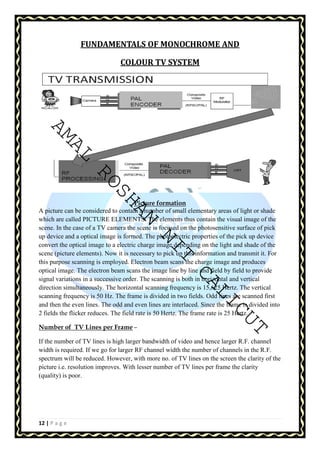
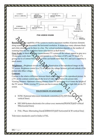
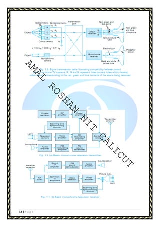
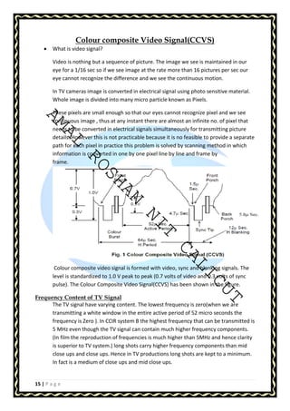
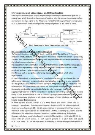
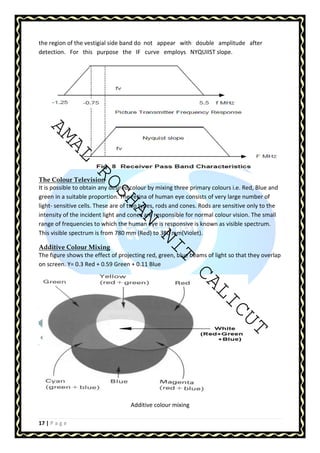
- Fundamentals of monochrome and colour TV systems, including picture formation, scanning, and interlacing.
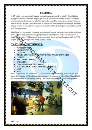
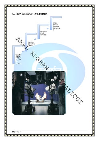
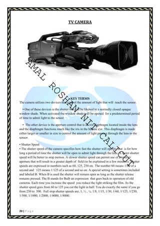
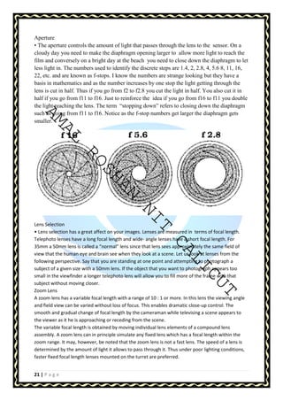
- Details of the studio setup and coverage at Doordarshan Patna, including cameras, transmitters, and facilities.