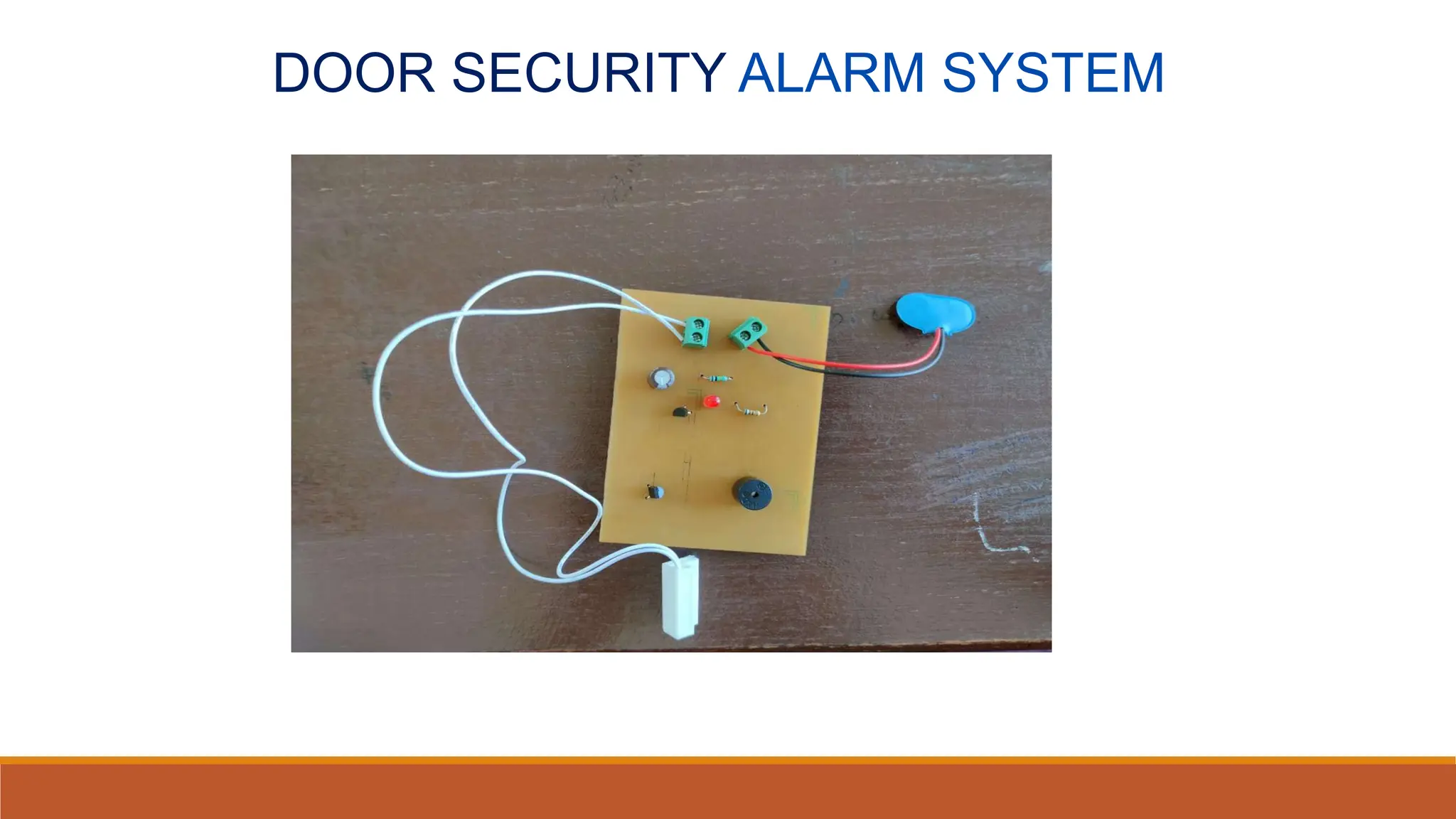
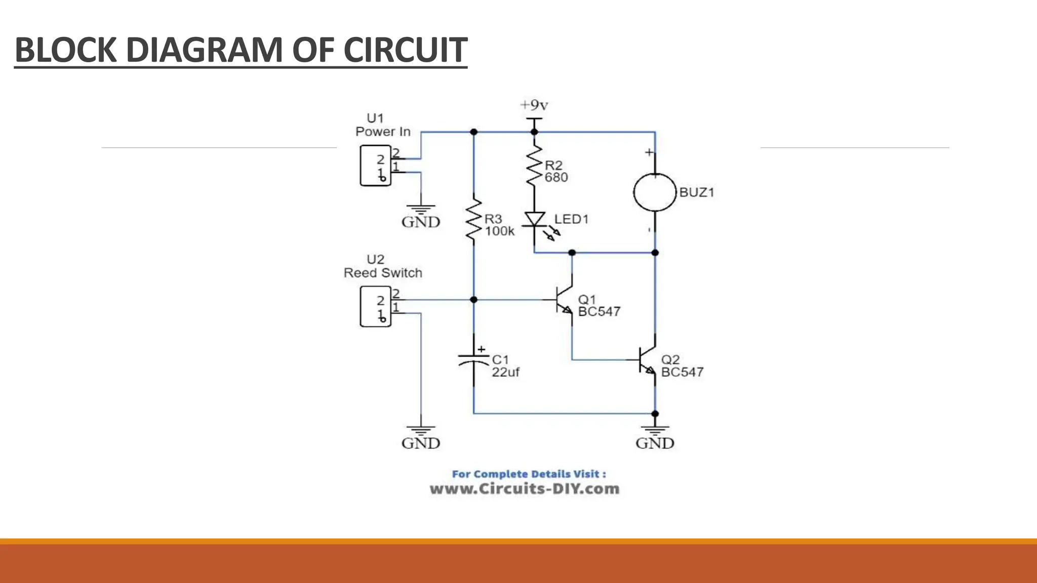
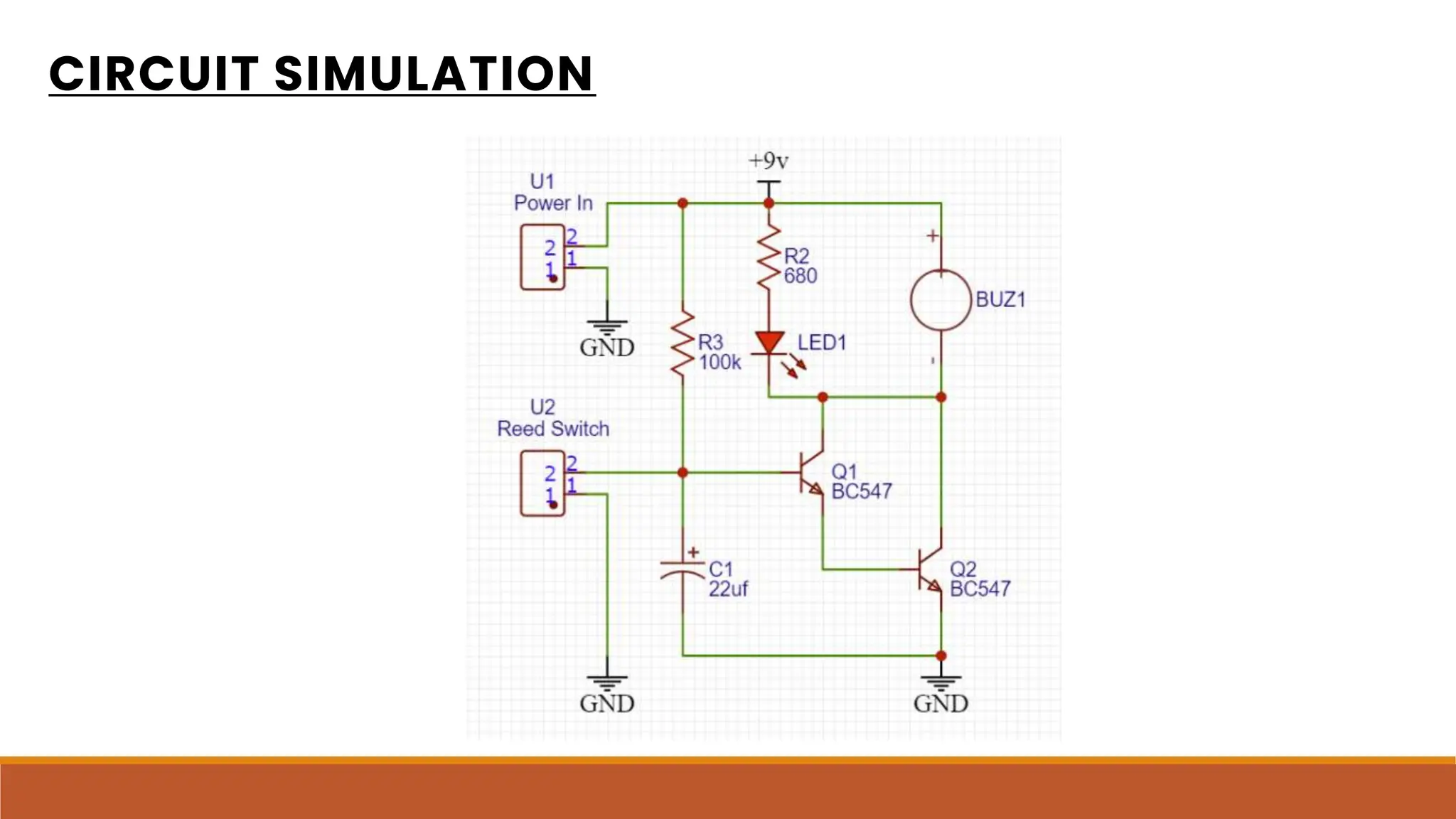
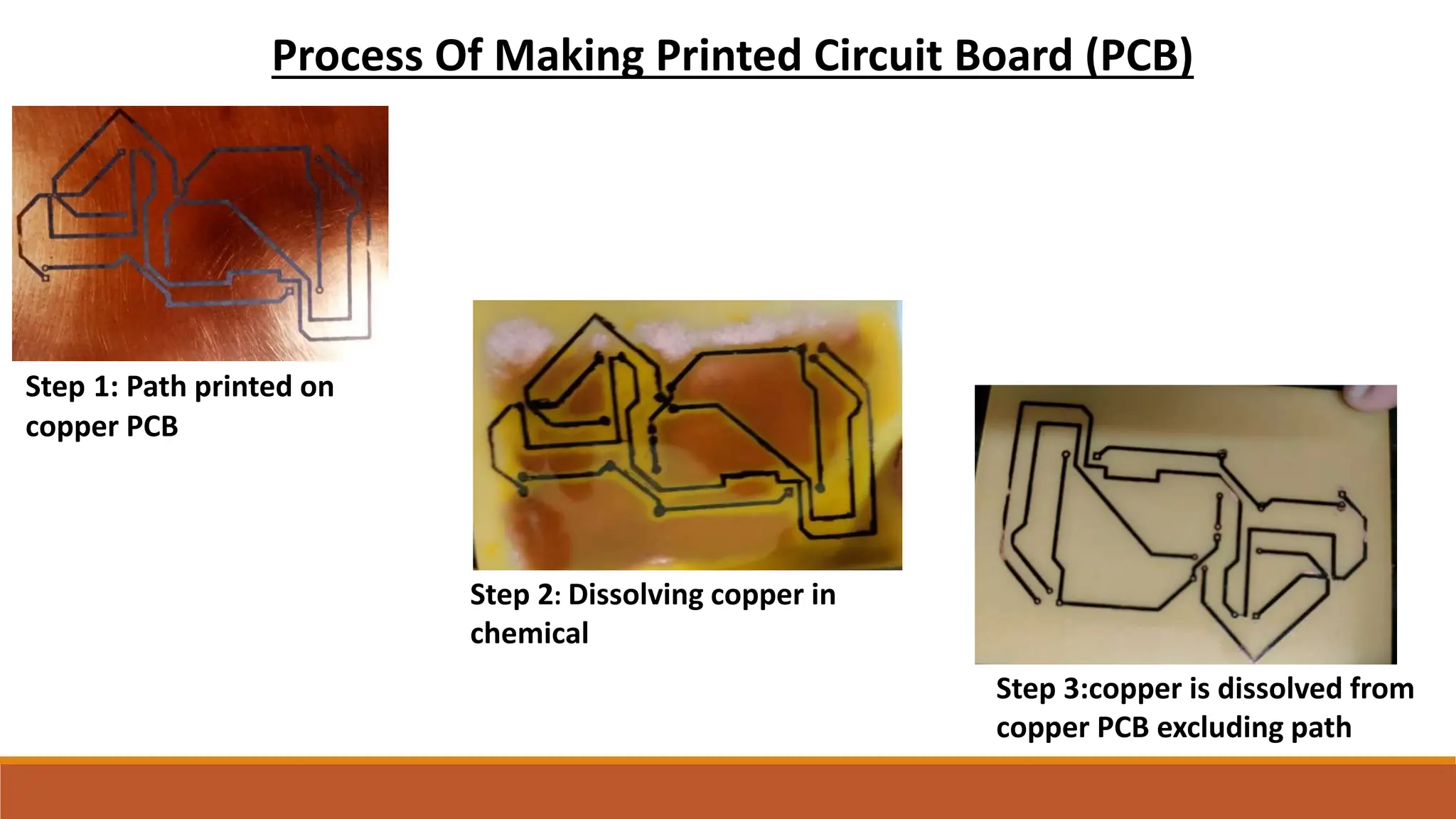
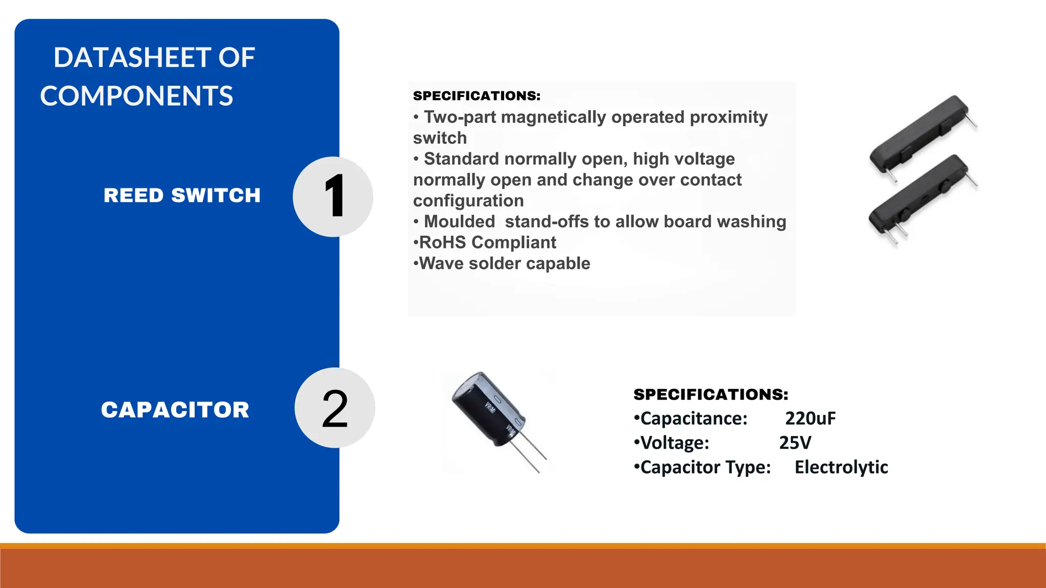
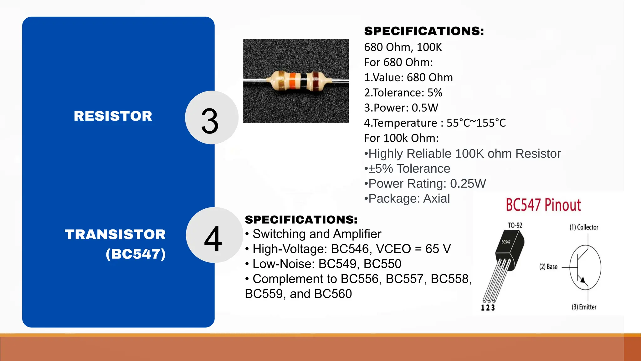
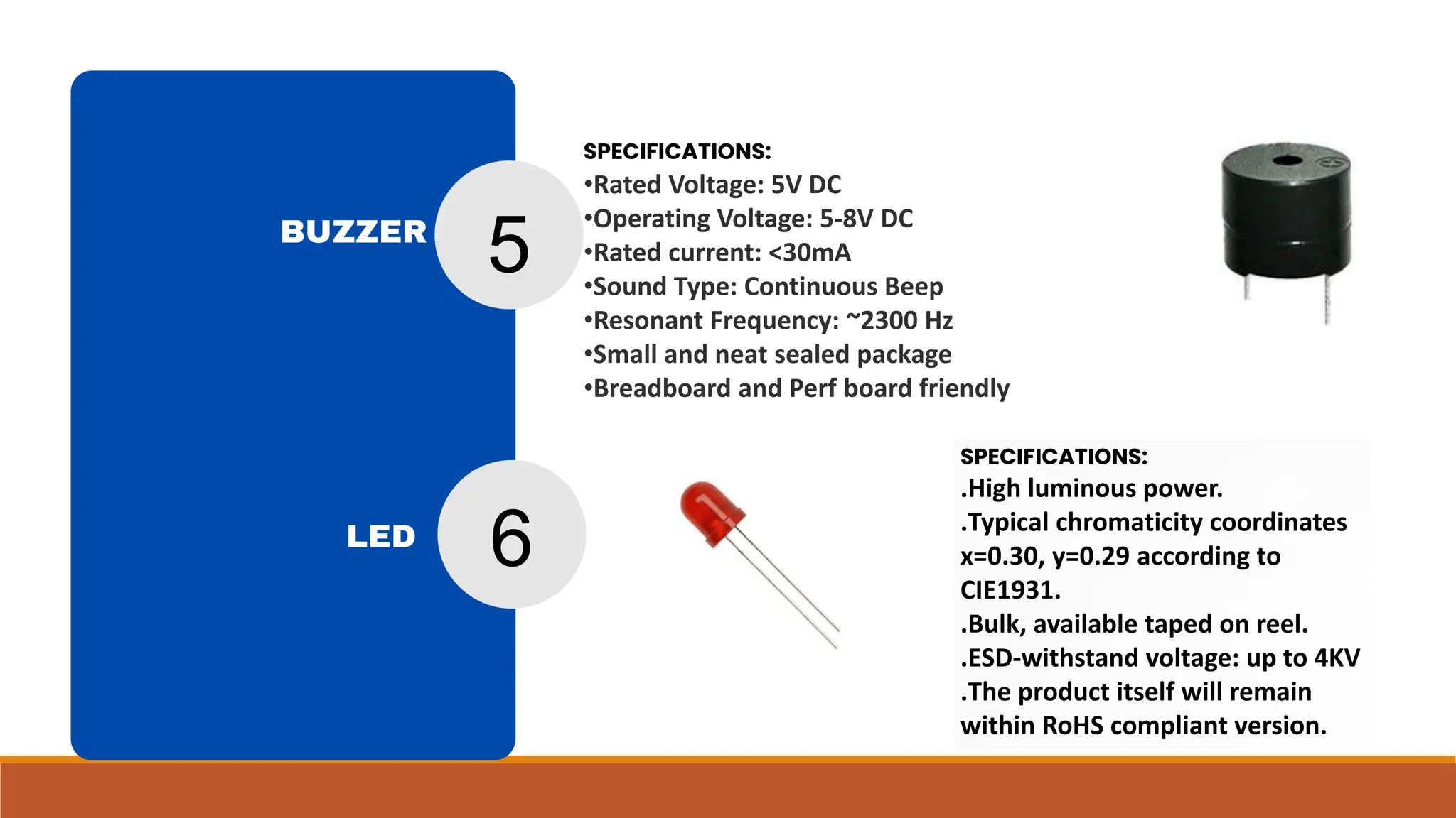
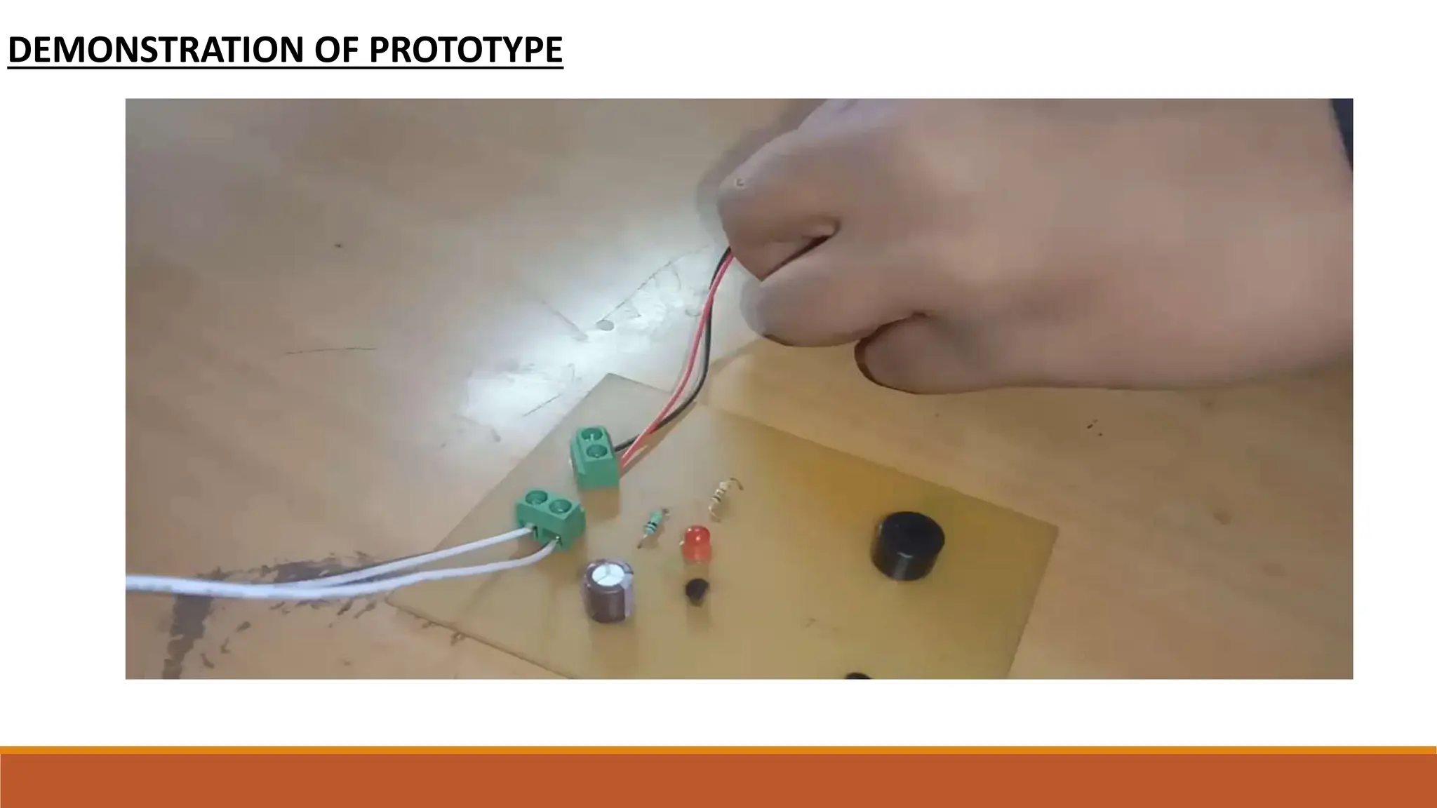
DOOR SECURITY ALARM SYSTEM
GUIDED BY:
Prof. Kalpana Pawse
Dr. prof. Mahesh Goudar
TEAM MEMBERS:
1.Vaishnav Lajurkar [E238]
2.Umesh Munde [E225]
3.Raviraj Sonar [E235]
DOOR SECURITY ALARM SYSTEM
UNDERSTANDING AND FUNCTIONING
 Security door alarms are simple electronic devices that trigger when an intruder or
trespasser tries to gain access to any designated area.
 They are a necessary part of today’s home security systems.
 There are a number of electronic configurations available to implement such home
security alarms. Here, we will take a look at implementing using a reed switch.
 The heart of this circuit is a magnetic reed switch.
 A reed switch comprises two ferromagnetic blades, separated by only a few microns.
 When another magnet comes close to these blades, the two blades pull towards one
another.
 Once touching, the blades close the normally open (NO) contacts, allowing electricity to
flow. Some reed switches also contain a non-ferromagnetic contact, which forms a
normally closed (NC) output. Any approaching magnet will disconnect the contact and
pull away from the switching contact.
WORKING & CONSTRUCTIONS:
This circuit can be attached to any entry point such as doors, gates, etc, or any storage unit
such as safes or drawers, where you want no intruders to trespass.
As the safe/door with one terminal of reed switch attached to the surface is opened & brought
close to the second terminal of the reed switch placed in close proximity.
The magnetic connection is made through mutual inductance & sends a control signal to the
base of the first BC547 transistor.
The collector output of the first transistor triggers the 5V buzzer & the alarm goes off.
 In order to turn off the alarm, you simply displace the door back to its original position, moving
the two reed switch terminals away from each other.
This demagnetizes the two terminals & turns OFF the alarm.
COMPONENTS USED IN CIRCUIT:
S.no Component Value Qty
1 Reed Switch – 1
2 NPN Transistor BC547 2
3 LED 5mm 1
4 Buzzer 5V 1
5 Resistor 680 Ohm, 100K 2
6 Capacitor 220uF 1
7 Soldering Iron 45W – 65W 1
8 Soldering wire with flux – 1
9 PCB – 1
10 DC Battery 9V 1
11 Battery clip – 1
12 Block Connectors – 1
BLOCK DIAGRAM OF CIRCUIT
CIRCUIT SIMULATION
PROTOTYPE ON BREADBOARD
CIRCUIT DESIGN ON KICAD
SCHEMATIC EDITOR
PCB EDITOR
PRINTED CIRCUIT
Process Of Making Printed Circuit Board (PCB)
Step 1: Path printed on
copper PCB
Step 2: Dissolving copper in
chemical
Step 3:copper is dissolved from
copper PCB excluding path
Step 4: By using sandpaper we clean
the circuit , then made holes for
assemble the components
Step 5: The Final Output
After assembling the components in PCB
SPECIFICATIONS:
• Two-part magnetically operated proximity
switch
• Standard normally open, high voltage
normally open and change over contact
configuration
• Moulded stand-offs to allow board washing
•RoHS Compliant
•Wave solder capable
DATASHEET OF
COMPONENTS
CAPACITOR
1
2
SPECIFICATIONS:
•Capacitance: 220uF
•Voltage: 25V
•Capacitor Type: Electrolytic
REED SWITCH
SPECIFICATIONS:
680 Ohm, 100K
For 680 Ohm:
1.Value: 680 Ohm
2.Tolerance: 5%
3.Power: 0.5W
4.Temperature : 55°C~155°C
For 100k Ohm:
•Highly Reliable 100K ohm Resistor
•±5% Tolerance
•Power Rating: 0.25W
•Package: Axial
SPECIFICATIONS:
• Switching and Amplifier
• High-Voltage: BC546, VCEO = 65 V
• Low-Noise: BC549, BC550
• Complement to BC556, BC557, BC558,
BC559, and BC560
RESISTOR
TRANSISTOR
(BC547)
3
4
SPECIFICATIONS:
․High luminous power.
․Typical chromaticity coordinates
x=0.30, y=0.29 according to
CIE1931.
․Bulk, available taped on reel.
․ESD-withstand voltage: up to 4KV
․The product itself will remain
within RoHS compliant version.
SPECIFICATIONS:
•Rated Voltage: 5V DC
•Operating Voltage: 5-8V DC
•Rated current: <30mA
•Sound Type: Continuous Beep
•Resonant Frequency: ~2300 Hz
•Small and neat sealed package
•Breadboard and Perf board friendly
5
BUZZER
6
LED
DEMONSTRATION OF PROTOTYPE
APPLICATIONS
1.Door Sensors:
1.Magnetic door/window sensors can be used to detect when a door is opened or closed.
2.These sensors typically consist of two parts: one attached to the door frame and the other
to the door itself.
2.Microcontroller/Single Board Computer:
1.Use a microcontroller (e.g., Arduino, Raspberry Pi) to interface with the door sensors and
manage the system.
2.Connect the sensors to the microcontroller to detect changes in the door status.
3.Wi-Fi/Bluetooth Module:
1.Integrate a Wi-Fi or Bluetooth module to enable communication between the
microcontroller and the application.
4.Alarm/Buzzer:
1.Include an alarm or buzzer to produce a loud sound when an unauthorized entry is
detected.
REFERENCES:
https://youtu.be/_j0csUukEzQ?si=yteuQXsHc_unjUiu
https://en.wikipedia.org/wiki/circuit
https://en.wikipedia.org/wiki/Transistor
https://www.electronicshub.org/what-is-reedswitch/
door security alarm circuit - electronics projects

door security alarm circuit - electronics projects

  • 1.
    DOOR SECURITY ALARMSYSTEM GUIDED BY: Prof. Kalpana Pawse Dr. prof. Mahesh Goudar TEAM MEMBERS: 1.Vaishnav Lajurkar [E238] 2.Umesh Munde [E225] 3.Raviraj Sonar [E235]
  • 2.
  • 3.
    UNDERSTANDING AND FUNCTIONING Security door alarms are simple electronic devices that trigger when an intruder or trespasser tries to gain access to any designated area.  They are a necessary part of today’s home security systems.  There are a number of electronic configurations available to implement such home security alarms. Here, we will take a look at implementing using a reed switch.  The heart of this circuit is a magnetic reed switch.  A reed switch comprises two ferromagnetic blades, separated by only a few microns.  When another magnet comes close to these blades, the two blades pull towards one another.  Once touching, the blades close the normally open (NO) contacts, allowing electricity to flow. Some reed switches also contain a non-ferromagnetic contact, which forms a normally closed (NC) output. Any approaching magnet will disconnect the contact and pull away from the switching contact.
  • 4.
    WORKING & CONSTRUCTIONS: Thiscircuit can be attached to any entry point such as doors, gates, etc, or any storage unit such as safes or drawers, where you want no intruders to trespass. As the safe/door with one terminal of reed switch attached to the surface is opened & brought close to the second terminal of the reed switch placed in close proximity. The magnetic connection is made through mutual inductance & sends a control signal to the base of the first BC547 transistor. The collector output of the first transistor triggers the 5V buzzer & the alarm goes off.  In order to turn off the alarm, you simply displace the door back to its original position, moving the two reed switch terminals away from each other. This demagnetizes the two terminals & turns OFF the alarm.
  • 5.
    COMPONENTS USED INCIRCUIT: S.no Component Value Qty 1 Reed Switch – 1 2 NPN Transistor BC547 2 3 LED 5mm 1 4 Buzzer 5V 1 5 Resistor 680 Ohm, 100K 2 6 Capacitor 220uF 1 7 Soldering Iron 45W – 65W 1 8 Soldering wire with flux – 1 9 PCB – 1 10 DC Battery 9V 1 11 Battery clip – 1 12 Block Connectors – 1
  • 6.
  • 7.
  • 8.
  • 9.
    CIRCUIT DESIGN ONKICAD SCHEMATIC EDITOR PCB EDITOR PRINTED CIRCUIT
  • 10.
    Process Of MakingPrinted Circuit Board (PCB) Step 1: Path printed on copper PCB Step 2: Dissolving copper in chemical Step 3:copper is dissolved from copper PCB excluding path
  • 11.
    Step 4: Byusing sandpaper we clean the circuit , then made holes for assemble the components Step 5: The Final Output After assembling the components in PCB
  • 12.
    SPECIFICATIONS: • Two-part magneticallyoperated proximity switch • Standard normally open, high voltage normally open and change over contact configuration • Moulded stand-offs to allow board washing •RoHS Compliant •Wave solder capable DATASHEET OF COMPONENTS CAPACITOR 1 2 SPECIFICATIONS: •Capacitance: 220uF •Voltage: 25V •Capacitor Type: Electrolytic REED SWITCH
  • 13.
    SPECIFICATIONS: 680 Ohm, 100K For680 Ohm: 1.Value: 680 Ohm 2.Tolerance: 5% 3.Power: 0.5W 4.Temperature : 55°C~155°C For 100k Ohm: •Highly Reliable 100K ohm Resistor •±5% Tolerance •Power Rating: 0.25W •Package: Axial SPECIFICATIONS: • Switching and Amplifier • High-Voltage: BC546, VCEO = 65 V • Low-Noise: BC549, BC550 • Complement to BC556, BC557, BC558, BC559, and BC560 RESISTOR TRANSISTOR (BC547) 3 4
  • 14.
    SPECIFICATIONS: ․High luminous power. ․Typicalchromaticity coordinates x=0.30, y=0.29 according to CIE1931. ․Bulk, available taped on reel. ․ESD-withstand voltage: up to 4KV ․The product itself will remain within RoHS compliant version. SPECIFICATIONS: •Rated Voltage: 5V DC •Operating Voltage: 5-8V DC •Rated current: <30mA •Sound Type: Continuous Beep •Resonant Frequency: ~2300 Hz •Small and neat sealed package •Breadboard and Perf board friendly 5 BUZZER 6 LED
  • 15.
  • 16.
    APPLICATIONS 1.Door Sensors: 1.Magnetic door/windowsensors can be used to detect when a door is opened or closed. 2.These sensors typically consist of two parts: one attached to the door frame and the other to the door itself. 2.Microcontroller/Single Board Computer: 1.Use a microcontroller (e.g., Arduino, Raspberry Pi) to interface with the door sensors and manage the system. 2.Connect the sensors to the microcontroller to detect changes in the door status. 3.Wi-Fi/Bluetooth Module: 1.Integrate a Wi-Fi or Bluetooth module to enable communication between the microcontroller and the application. 4.Alarm/Buzzer: 1.Include an alarm or buzzer to produce a loud sound when an unauthorized entry is detected.
  • 17.