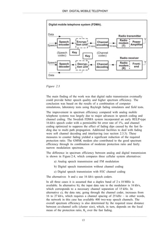
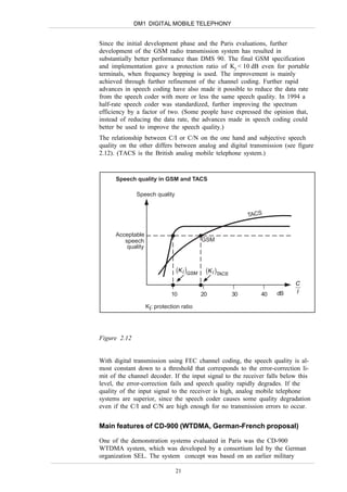
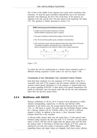
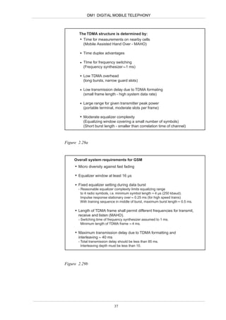
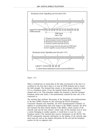
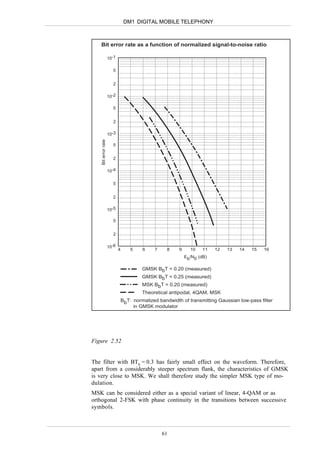
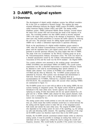
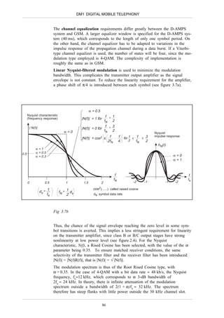
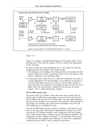
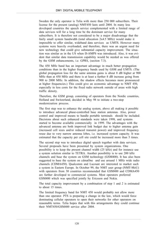
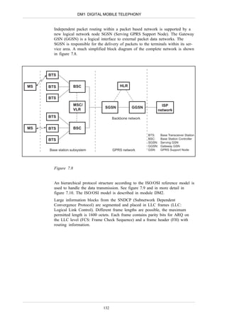
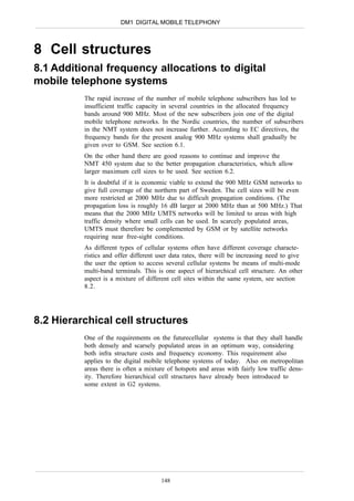
The GSM system was initiated by European telecom administrations to specify a pan-European digital cellular system. It was developed to provide at least the same speech quality and spectrum efficiency as analog systems at a lower cost. A TDMA scheme was chosen for multiple access after tests showed it could suppress interference better than FDMA. The GSM standard was developed through the late 1980s and early 1990s, with commercial launches beginning in 1992 allowing for services like roaming and authentication across Europe. Initial growth was slower in Scandinavia where existing NMT analog service was sufficient.

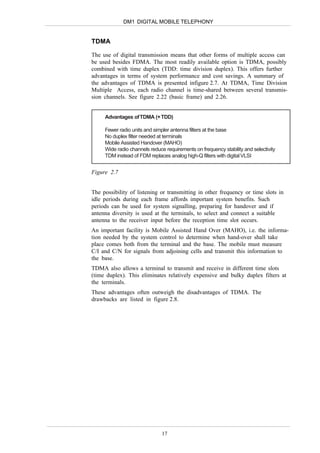
![DM1 DIGITAL MOBILE TELEPHONY
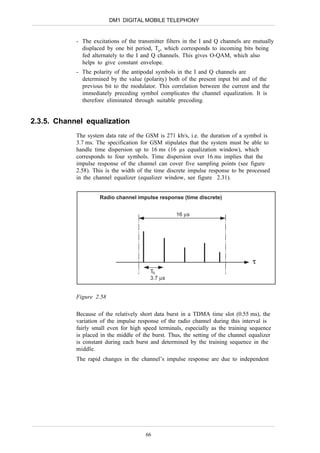
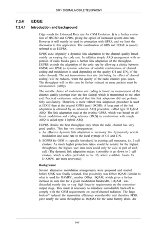
MSK as linear modulation (QAM)
± cos ( π t )
2Tb
D/A S
±
2Tb 4Tb cosω0t
±
db/2 t t f0
2Tb
db b/s
Coder ± ± v
Tb 3Tb Tb
90
3Tb
t t sinω0t
db = 1
Tb db/2
D/A S
± sin ( π t )
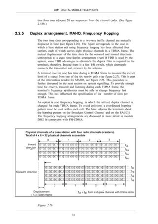
Impulse response of transmitter filter S: 2Tb
0 < t < 2Tb
v = ± sin ( π t ) cosω0t ± sin ( π t ) sinω0t =
2Tb 2Tb
t π 1
2Tb = cos (ω0 ± ) t = ± cos 2π( ƒ0 ± )t
2Tb 4Tb
(Ts = 2Tb)
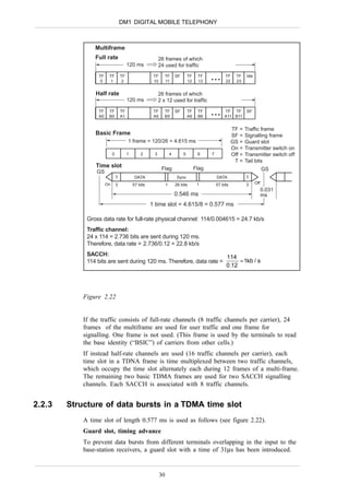
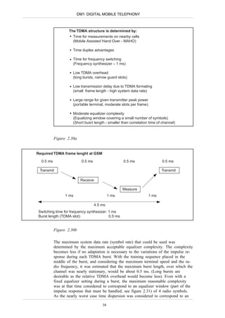
(The polarity of the exciting Dirac pulses is determined both by the preceding radio
symbols and by the value of the incoming baseband bit).
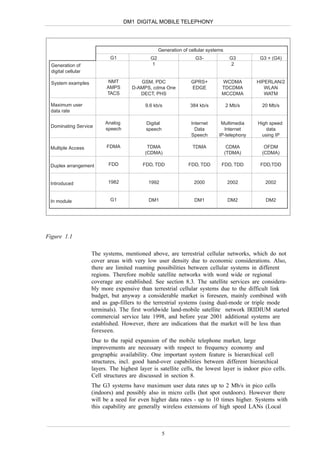
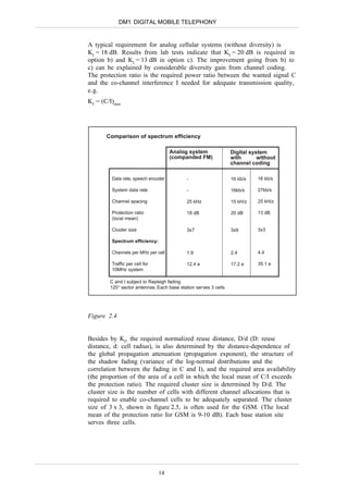
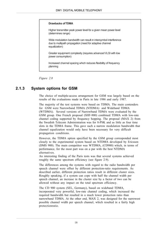
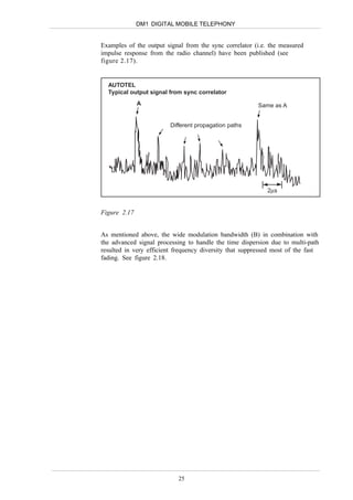
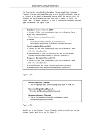
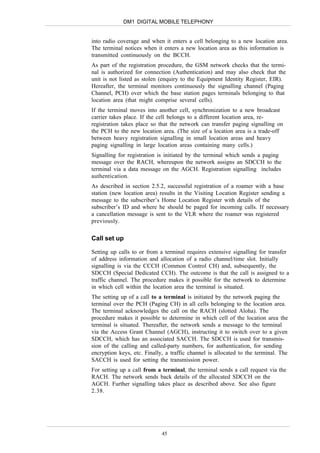
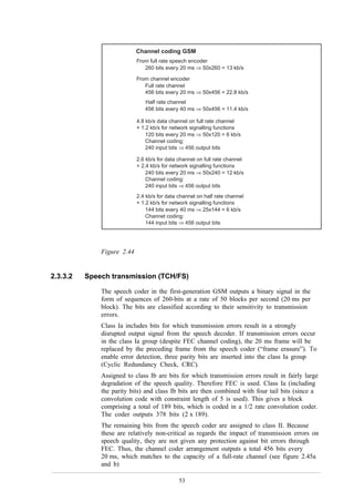
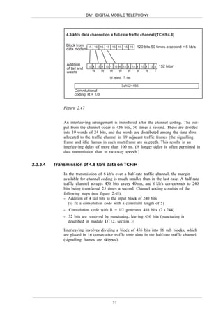
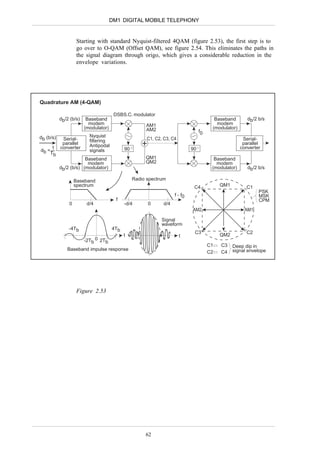
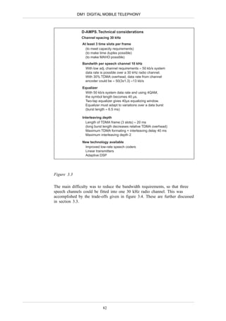
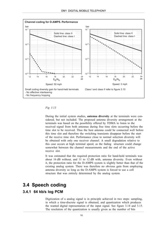
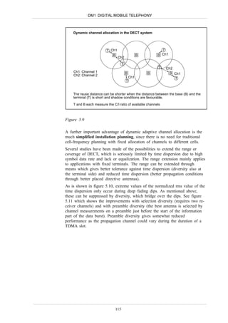
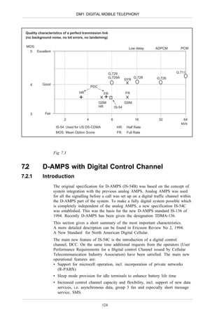
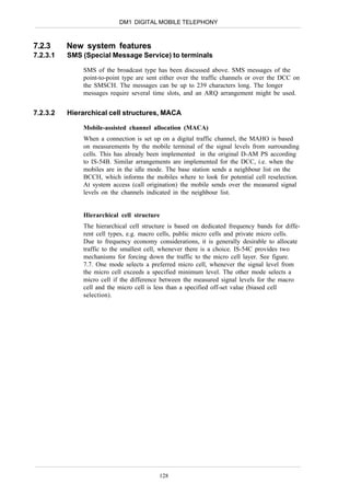
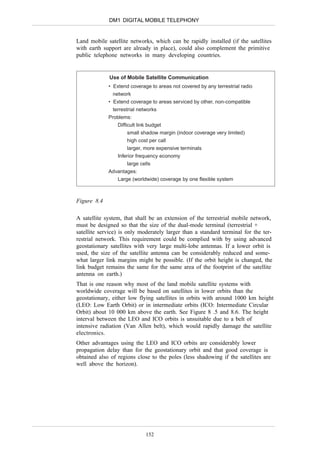
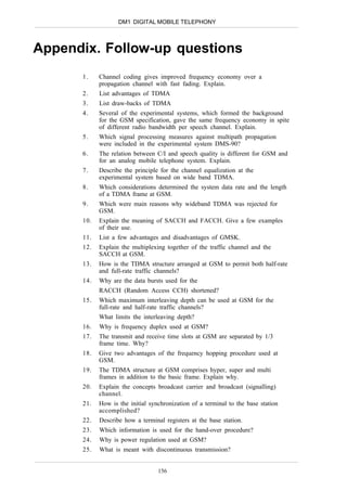
Figure 2.55
GMSK modulator (GMSK = Gaussian-filtered Minimum Shift Keying)
MSK interpreted as QAM (Complex signal representation)
10010110 Digital signal processing Radio monolithic circuit
in CMOS VLSI cosω0t
ƒ'i
Ib
ƒ'i φ' φ' cosω0t . cosφ
cos
cos(ω0t + φ)
∫ dt
Gaussian
(NRZ) filter
φ'
sin .
Qb -sinω0t sinφ
~
IsI = I
Complex envelope: -sinω0t
Q
φ ~
s = Ib +jQb = cosφ + jsinφ= ejφ ~
s
Qb = sinφ
~
φ' corresponds Complex signal: sejω0t = ej(ω0t+φ)
to MSK ~
Physical signal: Re[sejω0t] =cos(ω0t+φ) φ
~ I
φ corresponds (Normalize |s| =1 )
Ib = cosφ
to GMSK (cosω0tcosφ - sinω0tsinφ = cos(ω0t + φ)
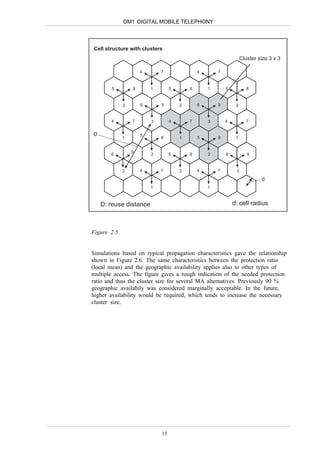
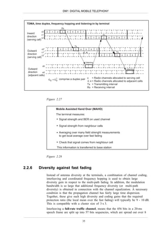
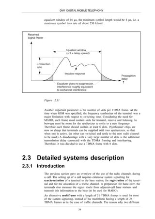
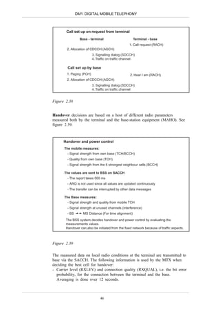
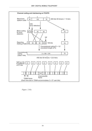
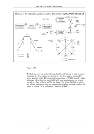
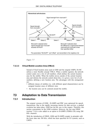
Figure 2.56
If instead MSK is considered as a form of FSK, the starting point is to
introduce phase continuity between consecutive s 2-FSK symbols. This
64](https://image.slidesharecdn.com/dm1e-130217202826-phpapp01/85/Dm1-e-64-320.jpg)
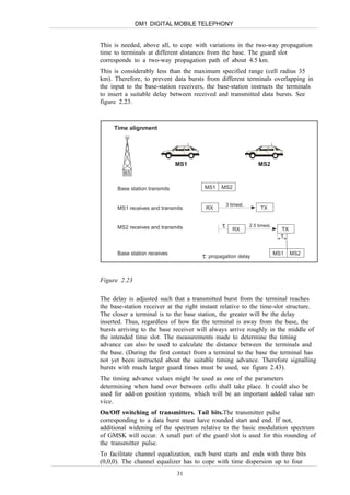
![DM1 DIGITAL MOBILE TELEPHONY
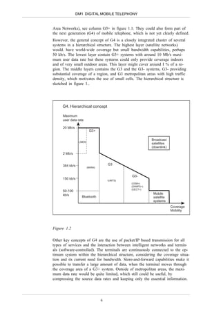
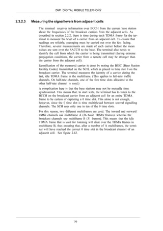
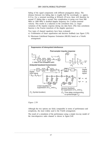
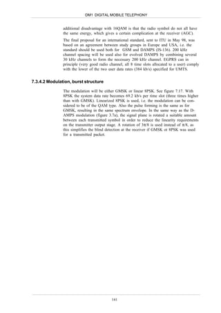
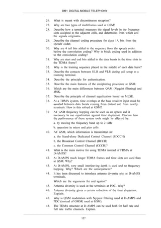
Amplifier stage. Relation between input and output levels
Class B/C
Pout
Class A
Pin
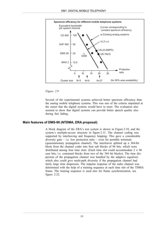
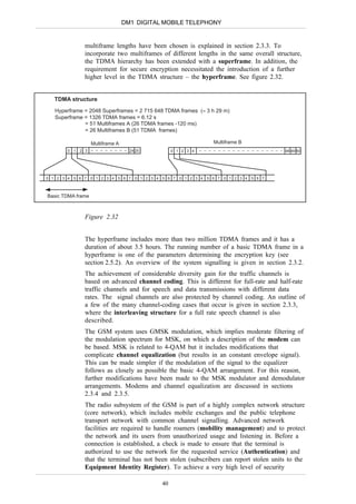
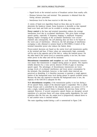
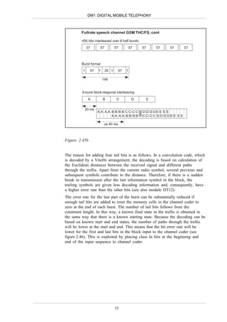
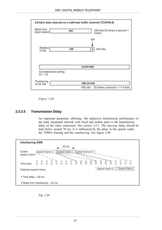
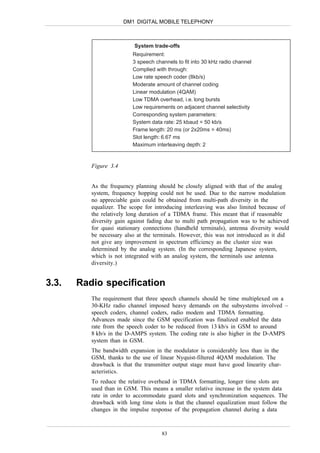
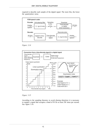
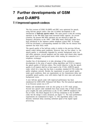
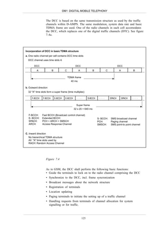
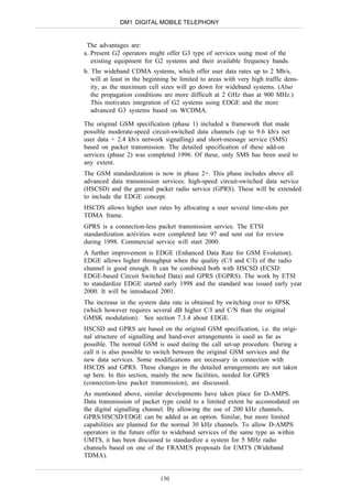
Figure 3.8
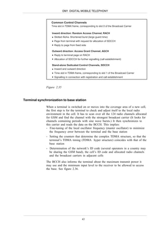
D-AMPS: p / 4-DQPSK modulation
Modulator for standard 4-QAM
~
s = Re [ s4-QAM - ejkπ/4 . ejω0t ]
D/A T(f)
db
/2 ejω0t
Serial- s Linear
db
transmitter
parallel ~
s4-QAM ejkπ/4 π/2
converter amplifier
db
/2
D/A T(f)
Tb = 1
db
Ts = 2Tb R(f)
ejω0t Receiver
kTs frontend
Channel
equalizer e-jkπ/4 π/2
~
s4-QAM
R(f)
kTs
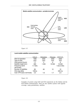
Nyquist characteristic: N(f) = T(f) . R(f)
(Differential coding omitted)
T(f): Transmitter filter response R(f): Receiver filter response
Fig 3.9
87](https://image.slidesharecdn.com/dm1e-130217202826-phpapp01/85/Dm1-e-87-320.jpg)
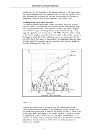
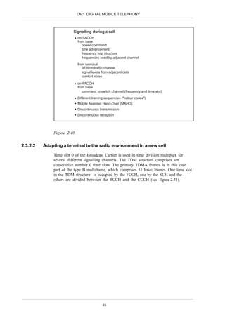
![DM1 DIGITAL MOBILE TELEPHONY
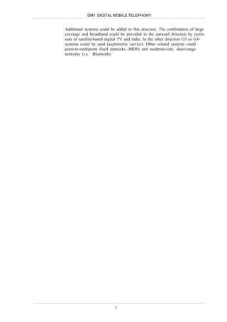
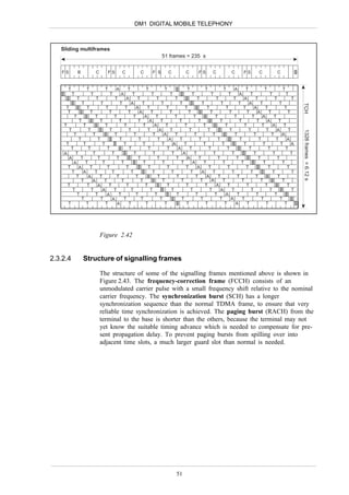
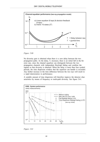
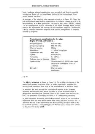
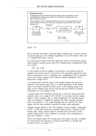
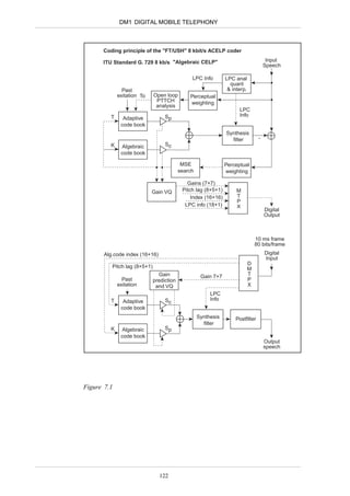
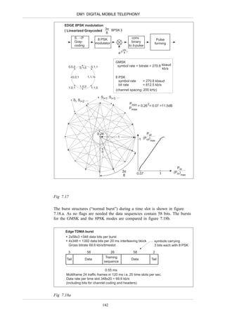
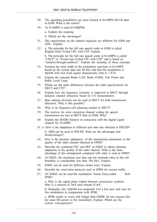
DECT: Relation between time structure of fading and delay spread
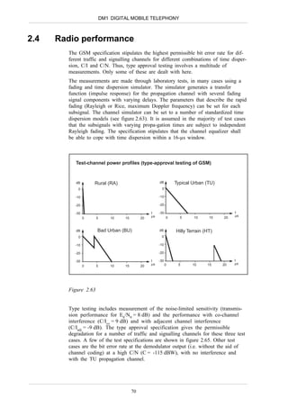
Fast fading average C/N0 = 83.7 dB.Hz
C/N0 [dB.Hz] 90 fd = 5Hz
80
70
60
Time (a)
Normalized delay spread τrmsRs =0.15
100
τrmsRs
101
102
Time (b)
τrms: Delay spread
Rs : System data rate
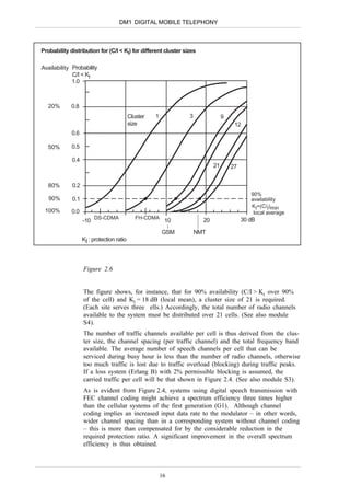
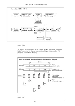
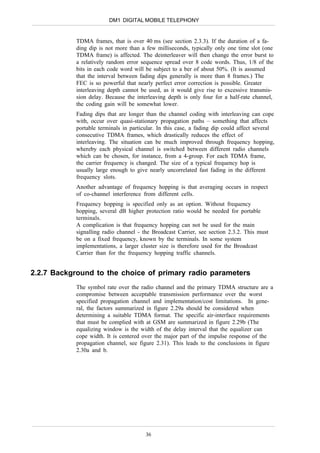
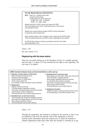
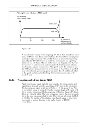
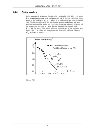
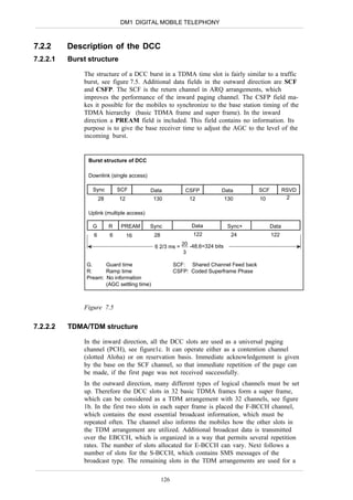
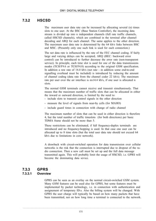
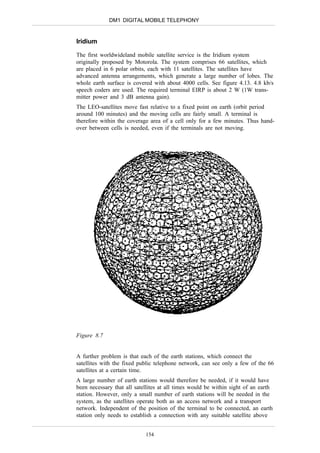
Figure 5.10
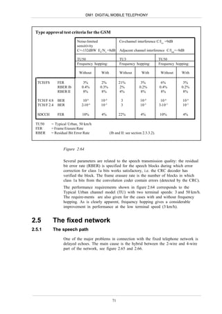
Diversity performance for different delay spreads
40
Required Eb/No to obtain 1%
35
failure rate (dB)
30
25
No diversity
20
Preamble diversity
Selection diversity
15
0 50 100 150 200 250 300 ns
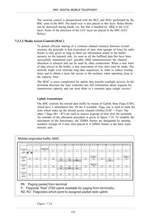
τrms
Figure 5.11
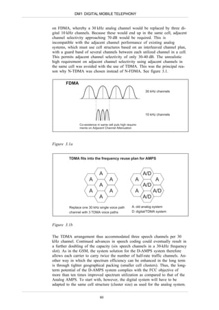
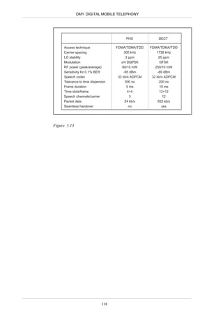
Typical values of the delay spread for different situations is indicated in
figure 5.12.
116](https://image.slidesharecdn.com/dm1e-130217202826-phpapp01/85/Dm1-e-116-320.jpg)


![C04 wireless telecommunication-systems[1]](https://cdn.slidesharecdn.com/ss_thumbnails/c04-wirelesstelecommunicationsystems1-130417045952-phpapp02-thumbnail.jpg?width=640&height=640&fit=bounds)