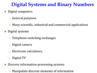
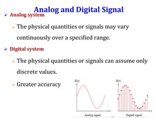
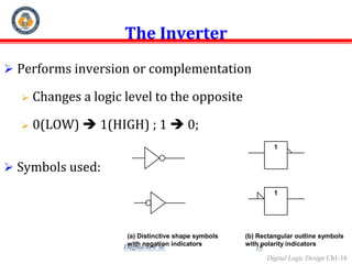
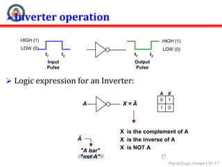
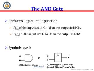
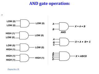
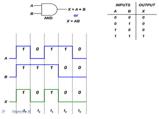
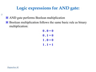
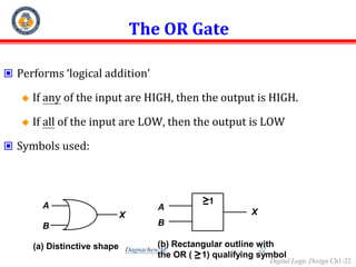
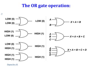
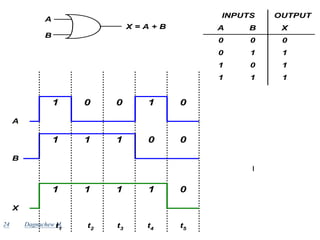
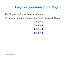
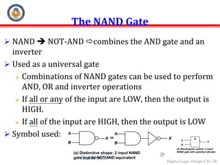
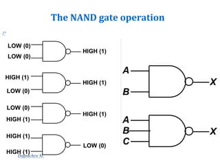
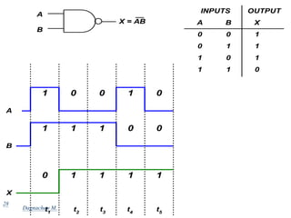
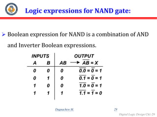
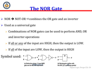
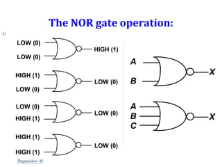
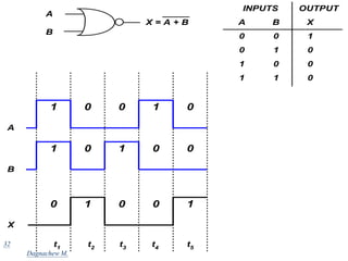
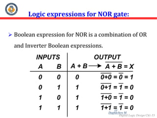
Digital Systems and Binary Numbers
by
Dagnachew .M
Digital Logic Design
Digital Systems and Binary Numbers
 Digital computers
 General purposes
 Many scientific, industrial and commercial applications
 Digital systems
 Telephone switching exchanges
 Digital camera
 Electronic calculators,
 Digital TV
 Discrete information-processing systems
 Manipulate discrete elements of information
Analog and Digital Signal
 Analog system
 The physical quantities or signals may vary
continuously over a specified range.
 Digital system
 The physical quantities or signals can assume only
discrete values.
 Greater accuracy
t
Binary Digital Signal
 Binary values are represented abstractly by:
 Digits 0 and 1
 Words (symbols) False (F) and True (T)
 Words (symbols) Low (L) and High (H)
 And words On and Off
 Binary values are represented by values
or ranges of values of physical quantities.
t
V(t)
Binary digital signal
Logic 1
Logic 0
undefine
Decimal Number System
 Base (also called radix) = 10
 10 digits { 0, 1, 2, 3, 4, 5, 6, 7, 8, 9 }
 Digit Position
 Integer & fraction
 Digit Weight
 Weight = (Base)
Position
 Magnitude
 Sum of “Digit x Weight”
1 0 -1
2 -2
5 1 2 7 4
10 1 0.1
100 0.01
500 10 2 0.7 0.04
d2*B2
+d1*B1
+d0*B0
+d-1*B-1
+d-2*B-2
(512.74)10
Octal Number System
 Base = 8
 8 digits { 0, 1, 2, 3, 4, 5, 6, 7 }
 Weights
 Weight = (Base)
Position
 Magnitude
 Sum of “Digit x Weight”
 Formal Notation
Binary Number System
 Base = 2
 2 digits { 0, 1 }, called binary digits or “bits”
 Weights
 Weight = (Base)
Position
 Magnitude
 Sum of “Bit x Weight”
 Formal Notation
 Groups of bits 4 bits = Nibble
8 bits = Byte
1 0 -1
2 -2
2 1 1/2
4 1/4
1 0 1 0 1
1 *22
+0 *21
+1 *20
+0 *2-1
+1 *2-
=(5.25)10
(101.01)2
1 0 1 1
1 1 0 0 0 1 0 1
Hexadecimal Number System
 Base = 16
 16 digits { 0, 1, 2, 3, 4, 5, 6, 7, 8, 9, A, B, C, D, E, F }
 Weights
 Weight = (Base)
Position
 Magnitude
 Sum of “Digit x Weight”
 Formal Notation
1 0 -1
2 -2
16 1 1/16
256 1/256
1 E 5 7 A
1 *162
+14 *161
+5 *160
+7 *16-1
+10 *16-2
=(485.4765625)10
(1E5.7A)16
The Power of 2
n 2n
0 20=1
1 21=2
2 22=4
3 23=8
4 24=16
5 25=32
6 26=64
7 27=128
n 2n
8 28=256
9 29=512
10 210=1024
11 211=2048
12 212=4096
20 220=1M
30 230=1G
40 240=1T
Mega
Giga
Tera
Kilo
Number Base Conversions
Decimal
(Base 10)
Octal
(Base 8)
Binary
(Base 2)
Hexadecimal
(Base 16)
Evaluate
Magnitude
Evaluate
Magnitude
Evaluate
Magnitude
Complements
 1’s Complement
 All ‘0’s become ‘1’s
 All ‘1’s become ‘0’s
Example (10110000)2
 (01001111)2
If you add a number and its 1’s complement …
1 0 1 1 0 0 0 0
+ 0 1 0 0 1 1 1 1
1 1 1 1 1 1 1 1
Complements
 2’s Complement
 Take 1’s complement then add 1
 Toggle all bits to the left of the first ‘1’ from the right
Example:
1’s Comp.:
0 1 0 1 0 0 0 0
1 0 1 1 0 0 0 0
0 1 0 0 1 1 1 1
+ 1
OR
1 0 1 1 0 0 0 0
0
0
0
0
1
0
1
0
Logic Gates
15
Dagnachew M.
Digital Logic Design Ch1-16
The Inverter
 Performs inversion or complementation
 Changes a logic level to the opposite
 0(LOW)  1(HIGH) ; 1  0;
 Symbols used:
1
1
(a) Distinctive shape symbols
with negation indicators
(b) Rectangular outline symbols
with polarity indicators
16
Dagnachew M.
Digital Logic Design Ch1-17
Inverter operation
 Logic expression for an Inverter:
t1
t2
t1
t2
HIGH (1)
LOW (0)
HIGH (1)
LOW (0)
Output
Pulse
Input
Pulse
A X = A
0 1
1 0
A X
X is the complement of A
X is the inverse of A
X is NOT A
A
"A bar"
"not A" 17
Dagnachew M.
Digital Logic Design Ch1-18
The AND Gate
 Performs ‘logical multiplication’
 If all of the input are HIGH, then the output is HIGH.
 If any of the input are LOW, then the output is LOW.
 Symbols used:
&
A
B
A
B
X
(a) Distinctive shape (b) Rectangular outline with
the AND (&) qualifying symbol
X
18
Dagnachew M.
AND gate operation:
LOW (0)
LOW (0)
LOW (0)
LOW (0)
HIGH (1)
LOW (0)
LOW (0)
LOW (0)
HIGH (1)
HIGH (1)
HIGH (1)
HIGH (1)
A
B
X = ABCD
C
D
A
C
B X = A B C
A
B
AND
X = A B
19
Dagnachew M.
20
A B X
INPUTS OUTPUT
0 0 0
0 1 0
1 0 0
1 1 1
A
B
AND
X = A B
X = AB
or
1 1 1
0 0
A
1 1 0
1 0
B
X
1 1 0
0 0
t1
t2
t3
t4
t5
Dagnachew M.
Logic expressions for AND gate:
21
 AND gate performs Boolean multiplication
 Boolean multiplication follows the same basic rule as binary
multiplication:
0 . 0 = 0
0 . 1 = 0
1 . 0 = 0
1 . 1 = 1
Dagnachew M.
Digital Logic Design Ch1-22
The OR Gate
 Performs ‘logical addition’
 If any of the input are HIGH, then the output is HIGH.
 If all of the input are LOW, then the output is LOW
 Symbols used:
1
A
B
A
B
X
(a) Distinctive shape (b) Rectangular outline with
the OR ( 1) qualifying symbol
X
22
Dagnachew M.
The OR gate operation:
LOW (0)
LOW (0)
LOW (0)
HIGH (1)
HIGH (1)
LOW (0)
HIGH (1)
LOW (0)
HIGH (1)
HIGH (1)
HIGH (1)
HIGH (1)
A
B
X = A + B
A
C
X = A + B + C
B
A
C
X = A + B + C + D
B
D
23
Dagnachew M.
24
A B X
INPUTS OUTPUT
0 0 0
0 1 1
1 0 1
1 1 1
A
B
X = A + B
1 0 1
0 0
A
1 1 0
1 0
B
X
1 1 1
1 0
t1
t2
t3
t4
t5
Dagnachew M.
Logic expressions for OR gate:
25
 OR gate performs Boolean addition
 Boolean addition follows the basic rules as follows:
0 + 0 = 0
0 + 1 = 1
1 + 0 = 1
1 + 1 = 1
Dagnachew M.
Digital Logic Design Ch1-26
The NAND Gate
 NAND  NOT-AND combines the AND gate and an
inverter
 Used as a universal gate
 Combinations of NAND gates can be used to perform
AND, OR and inverter operations
 If all or any of the input are LOW, then the output is
HIGH.
 If all of the input are HIGH, then the output is LOW
 Symbol used: A
B
X
A
B
X
(a) Distinctive shape: 2 input NAND
gate and its NOT/AND equivalent
&
A
B
X
(b) Rectangular outline: 2 input
NAND gate with polarity indicator
26
Dagnachew M.
The NAND gate operation
HIGH (1)
LOW (0)
LOW (0)
HIGH (1)
HIGH (1)
LOW (0)
HIGH (1)
LOW (0)
HIGH (1)
LOW (0)
HIGH (1)
HIGH (1)
A
B
X
A
C
X
B
27
Dagnachew M.
28
A B X
INPUTS OUTPUT
0 0 1
0 1 1
1 0 1
1 1 0
1 0 1
0 0
A
1 1 0
1 0
B
X
0 1 1
1 1
t1
t2
t3
t4
t5
A
B
X = AB
Dagnachew M.
Digital Logic Design Ch1-29
Logic expressions for NAND gate:
 Boolean expression for NAND is a combination of AND
and Inverter Boolean expressions.
A B AB
INPUTS OUTPUT
0 0 0
0 1 0
1 0 0
1 1 1
AB = X
0.0 = 0 = 1
0.1 = 0 = 1
1.0 = 0 = 1
1.1 = 1 = 0
29
Dagnachew M.
Digital Logic Design Ch1-30
The NOR Gate
 NOR  NOT-OR combines the OR gate and an inverter
 Used as a universal gate
 Combinations of NOR gates can be used to perform AND, OR
and inverter operations
 If all or any of the input are HIGH, then the output is LOW.
 If all of the input are LOW, then the output is HIGH
Symbol used:
(a) Distinctive shape: 2 input NOR
gate and its NOT/OR equivalent
A
B
X
1
A
B
X
(b) Rectangular outline with
the OR ( 1) qualifying symbol
A
B
X
30
Dagnachew M.
The NOR gate operation:
HIGH (1)
LOW (0)
LOW (0)
LOW (0)
HIGH (1)
LOW (0)
LOW (0)
LOW (0)
HIGH (1)
LOW (0)
HIGH (1)
HIGH (1)
A
B
X
A
C
X
B
31
Dagnachew M.
32
A B X
INPUTS OUTPUT
0 0 1
0 1 0
1 0 0
1 1 0
A
B
X = A + B
1 0 1
0 0
A
1 1 0
0 0
B
X
0 0 0
1 1
t1
t2
t3
t4
t5
Dagnachew M.
Digital Logic Design Ch1-33
Logic expressions for NOR gate:
 Boolean expression for NOR is a combination of OR
and Inverter Boolean expressions.
A B A + B
INPUTS OUTPUT
0 0 0
0 1 1
1 0 1
1 1 1
A + B = X
0+0 = 0 = 1
0+1 = 1 = 0
1+0 = 1 = 0
1+1 = 1 = 0
33
Dagnachew M.
Digital Logic Design Ch1-34
The Exclusive-OR gate
 Combines basic logic circuits of AND, OR and Inverter. Has only 2 inputs
 Used as a universal gate
 Can be connected to form an adder that allows a computer to do perform
addition, subtraction, multiplication and division in ALU
 If both of the input are at the same logic level, then the output is LOW.
 If both of the input are at opposite logic levels, then the output is HIGH
Symbol used:
(a) Distinctive shape
A
B
X
= 1
A
B
X
(b) Rectangular outline
34
Dagnachew M.
The XOR gate operation:
LOW (0)
LOW (0)
LOW (0)
HIGH (1)
HIGH (1)
LOW (0)
HIGH (1)
LOW (0)
HIGH (1)
LOW (0)
HIGH (1)
HIGH (1)
A
B
X
35
Dagnachew M.
36
A B X
INPUTS OUTPUT
0 0 0
0 1 1
1 0 1
1 1 0
A
B
X = AB + BA
= A B
1 0 1
0 0
A
1 1 0
0 0
B
X
0 1 1
0 0
t1
t2
t3
t4
t5
Sama  0
Tak sama 1
Dagnachew M.
Digital Logic Design Ch1-37
The Exclusive-NOR gate
 Has only 2 inputs, but output of XNOR is the opposite of XOR
 If both of the input are at the same logic level, then the output
is HIGH.
 If both of the input are at opposite logic levels, then the
output is LOW.
Symbol used:
(a) Distinctive shape
A
B
X
= 1
A
B
X
(b) Rectangular outline
37
Dagnachew M.
The XNOR gate operation:
A
B
X
38
LOW (1)
LOW (0)
LOW (0)
HIGH (0)
HIGH (1)
LOW (0)
HIGH (0)
LOW (0)
HIGH (1)
LOW (1)
HIGH (1)
HIGH (1)
Dagnachew M.
39
A B X
INPUTS OUTPUT
0 0 1
0 1 0
1 0 0
1 1 1
A
B
X = A B
1 0 1
0 0
A
1 1 0
0 0
B
X
1 0 0
1 1
t1
t2
t3
t4
t5
Dagnachew M.
XOR vs XNOR
40
1 0 1
0 0
A
1 1 0
0 0
B
XOR
0 1 1
0 0
t1
t2
t3
t4
t5
1 0 0
1 1
XNOR
Dagnachew M.

dld.ppt

  • 1.
    Digital Systems andBinary Numbers by Dagnachew .M Digital Logic Design
  • 2.
    Digital Systems andBinary Numbers  Digital computers  General purposes  Many scientific, industrial and commercial applications  Digital systems  Telephone switching exchanges  Digital camera  Electronic calculators,  Digital TV  Discrete information-processing systems  Manipulate discrete elements of information
  • 3.
    Analog and DigitalSignal  Analog system  The physical quantities or signals may vary continuously over a specified range.  Digital system  The physical quantities or signals can assume only discrete values.  Greater accuracy t
  • 4.
    Binary Digital Signal Binary values are represented abstractly by:  Digits 0 and 1  Words (symbols) False (F) and True (T)  Words (symbols) Low (L) and High (H)  And words On and Off  Binary values are represented by values or ranges of values of physical quantities. t V(t) Binary digital signal Logic 1 Logic 0 undefine
  • 5.
    Decimal Number System Base (also called radix) = 10  10 digits { 0, 1, 2, 3, 4, 5, 6, 7, 8, 9 }  Digit Position  Integer & fraction  Digit Weight  Weight = (Base) Position  Magnitude  Sum of “Digit x Weight” 1 0 -1 2 -2 5 1 2 7 4 10 1 0.1 100 0.01 500 10 2 0.7 0.04 d2*B2 +d1*B1 +d0*B0 +d-1*B-1 +d-2*B-2 (512.74)10
  • 6.
    Octal Number System Base = 8  8 digits { 0, 1, 2, 3, 4, 5, 6, 7 }  Weights  Weight = (Base) Position  Magnitude  Sum of “Digit x Weight”  Formal Notation
  • 7.
    Binary Number System Base = 2  2 digits { 0, 1 }, called binary digits or “bits”  Weights  Weight = (Base) Position  Magnitude  Sum of “Bit x Weight”  Formal Notation  Groups of bits 4 bits = Nibble 8 bits = Byte 1 0 -1 2 -2 2 1 1/2 4 1/4 1 0 1 0 1 1 *22 +0 *21 +1 *20 +0 *2-1 +1 *2- =(5.25)10 (101.01)2 1 0 1 1 1 1 0 0 0 1 0 1
  • 8.
    Hexadecimal Number System Base = 16  16 digits { 0, 1, 2, 3, 4, 5, 6, 7, 8, 9, A, B, C, D, E, F }  Weights  Weight = (Base) Position  Magnitude  Sum of “Digit x Weight”  Formal Notation 1 0 -1 2 -2 16 1 1/16 256 1/256 1 E 5 7 A 1 *162 +14 *161 +5 *160 +7 *16-1 +10 *16-2 =(485.4765625)10 (1E5.7A)16
  • 9.
    The Power of2 n 2n 0 20=1 1 21=2 2 22=4 3 23=8 4 24=16 5 25=32 6 26=64 7 27=128 n 2n 8 28=256 9 29=512 10 210=1024 11 211=2048 12 212=4096 20 220=1M 30 230=1G 40 240=1T Mega Giga Tera Kilo
  • 10.
    Number Base Conversions Decimal (Base10) Octal (Base 8) Binary (Base 2) Hexadecimal (Base 16) Evaluate Magnitude Evaluate Magnitude Evaluate Magnitude
  • 11.
    Complements  1’s Complement All ‘0’s become ‘1’s  All ‘1’s become ‘0’s Example (10110000)2  (01001111)2 If you add a number and its 1’s complement … 1 0 1 1 0 0 0 0 + 0 1 0 0 1 1 1 1 1 1 1 1 1 1 1 1
  • 12.
    Complements  2’s Complement Take 1’s complement then add 1  Toggle all bits to the left of the first ‘1’ from the right Example: 1’s Comp.: 0 1 0 1 0 0 0 0 1 0 1 1 0 0 0 0 0 1 0 0 1 1 1 1 + 1 OR 1 0 1 1 0 0 0 0 0 0 0 0 1 0 1 0
  • 15.
  • 16.
    Digital Logic DesignCh1-16 The Inverter  Performs inversion or complementation  Changes a logic level to the opposite  0(LOW)  1(HIGH) ; 1  0;  Symbols used: 1 1 (a) Distinctive shape symbols with negation indicators (b) Rectangular outline symbols with polarity indicators 16 Dagnachew M.
  • 17.
    Digital Logic DesignCh1-17 Inverter operation  Logic expression for an Inverter: t1 t2 t1 t2 HIGH (1) LOW (0) HIGH (1) LOW (0) Output Pulse Input Pulse A X = A 0 1 1 0 A X X is the complement of A X is the inverse of A X is NOT A A "A bar" "not A" 17 Dagnachew M.
  • 18.
    Digital Logic DesignCh1-18 The AND Gate  Performs ‘logical multiplication’  If all of the input are HIGH, then the output is HIGH.  If any of the input are LOW, then the output is LOW.  Symbols used: & A B A B X (a) Distinctive shape (b) Rectangular outline with the AND (&) qualifying symbol X 18 Dagnachew M.
  • 19.
    AND gate operation: LOW(0) LOW (0) LOW (0) LOW (0) HIGH (1) LOW (0) LOW (0) LOW (0) HIGH (1) HIGH (1) HIGH (1) HIGH (1) A B X = ABCD C D A C B X = A B C A B AND X = A B 19 Dagnachew M.
  • 20.
    20 A B X INPUTSOUTPUT 0 0 0 0 1 0 1 0 0 1 1 1 A B AND X = A B X = AB or 1 1 1 0 0 A 1 1 0 1 0 B X 1 1 0 0 0 t1 t2 t3 t4 t5 Dagnachew M.
  • 21.
    Logic expressions forAND gate: 21  AND gate performs Boolean multiplication  Boolean multiplication follows the same basic rule as binary multiplication: 0 . 0 = 0 0 . 1 = 0 1 . 0 = 0 1 . 1 = 1 Dagnachew M.
  • 22.
    Digital Logic DesignCh1-22 The OR Gate  Performs ‘logical addition’  If any of the input are HIGH, then the output is HIGH.  If all of the input are LOW, then the output is LOW  Symbols used: 1 A B A B X (a) Distinctive shape (b) Rectangular outline with the OR ( 1) qualifying symbol X 22 Dagnachew M.
  • 23.
    The OR gateoperation: LOW (0) LOW (0) LOW (0) HIGH (1) HIGH (1) LOW (0) HIGH (1) LOW (0) HIGH (1) HIGH (1) HIGH (1) HIGH (1) A B X = A + B A C X = A + B + C B A C X = A + B + C + D B D 23 Dagnachew M.
  • 24.
    24 A B X INPUTSOUTPUT 0 0 0 0 1 1 1 0 1 1 1 1 A B X = A + B 1 0 1 0 0 A 1 1 0 1 0 B X 1 1 1 1 0 t1 t2 t3 t4 t5 Dagnachew M.
  • 25.
    Logic expressions forOR gate: 25  OR gate performs Boolean addition  Boolean addition follows the basic rules as follows: 0 + 0 = 0 0 + 1 = 1 1 + 0 = 1 1 + 1 = 1 Dagnachew M.
  • 26.
    Digital Logic DesignCh1-26 The NAND Gate  NAND  NOT-AND combines the AND gate and an inverter  Used as a universal gate  Combinations of NAND gates can be used to perform AND, OR and inverter operations  If all or any of the input are LOW, then the output is HIGH.  If all of the input are HIGH, then the output is LOW  Symbol used: A B X A B X (a) Distinctive shape: 2 input NAND gate and its NOT/AND equivalent & A B X (b) Rectangular outline: 2 input NAND gate with polarity indicator 26 Dagnachew M.
  • 27.
    The NAND gateoperation HIGH (1) LOW (0) LOW (0) HIGH (1) HIGH (1) LOW (0) HIGH (1) LOW (0) HIGH (1) LOW (0) HIGH (1) HIGH (1) A B X A C X B 27 Dagnachew M.
  • 28.
    28 A B X INPUTSOUTPUT 0 0 1 0 1 1 1 0 1 1 1 0 1 0 1 0 0 A 1 1 0 1 0 B X 0 1 1 1 1 t1 t2 t3 t4 t5 A B X = AB Dagnachew M.
  • 29.
    Digital Logic DesignCh1-29 Logic expressions for NAND gate:  Boolean expression for NAND is a combination of AND and Inverter Boolean expressions. A B AB INPUTS OUTPUT 0 0 0 0 1 0 1 0 0 1 1 1 AB = X 0.0 = 0 = 1 0.1 = 0 = 1 1.0 = 0 = 1 1.1 = 1 = 0 29 Dagnachew M.
  • 30.
    Digital Logic DesignCh1-30 The NOR Gate  NOR  NOT-OR combines the OR gate and an inverter  Used as a universal gate  Combinations of NOR gates can be used to perform AND, OR and inverter operations  If all or any of the input are HIGH, then the output is LOW.  If all of the input are LOW, then the output is HIGH Symbol used: (a) Distinctive shape: 2 input NOR gate and its NOT/OR equivalent A B X 1 A B X (b) Rectangular outline with the OR ( 1) qualifying symbol A B X 30 Dagnachew M.
  • 31.
    The NOR gateoperation: HIGH (1) LOW (0) LOW (0) LOW (0) HIGH (1) LOW (0) LOW (0) LOW (0) HIGH (1) LOW (0) HIGH (1) HIGH (1) A B X A C X B 31 Dagnachew M.
  • 32.
    32 A B X INPUTSOUTPUT 0 0 1 0 1 0 1 0 0 1 1 0 A B X = A + B 1 0 1 0 0 A 1 1 0 0 0 B X 0 0 0 1 1 t1 t2 t3 t4 t5 Dagnachew M.
  • 33.
    Digital Logic DesignCh1-33 Logic expressions for NOR gate:  Boolean expression for NOR is a combination of OR and Inverter Boolean expressions. A B A + B INPUTS OUTPUT 0 0 0 0 1 1 1 0 1 1 1 1 A + B = X 0+0 = 0 = 1 0+1 = 1 = 0 1+0 = 1 = 0 1+1 = 1 = 0 33 Dagnachew M.
  • 34.
    Digital Logic DesignCh1-34 The Exclusive-OR gate  Combines basic logic circuits of AND, OR and Inverter. Has only 2 inputs  Used as a universal gate  Can be connected to form an adder that allows a computer to do perform addition, subtraction, multiplication and division in ALU  If both of the input are at the same logic level, then the output is LOW.  If both of the input are at opposite logic levels, then the output is HIGH Symbol used: (a) Distinctive shape A B X = 1 A B X (b) Rectangular outline 34 Dagnachew M.
  • 35.
    The XOR gateoperation: LOW (0) LOW (0) LOW (0) HIGH (1) HIGH (1) LOW (0) HIGH (1) LOW (0) HIGH (1) LOW (0) HIGH (1) HIGH (1) A B X 35 Dagnachew M.
  • 36.
    36 A B X INPUTSOUTPUT 0 0 0 0 1 1 1 0 1 1 1 0 A B X = AB + BA = A B 1 0 1 0 0 A 1 1 0 0 0 B X 0 1 1 0 0 t1 t2 t3 t4 t5 Sama  0 Tak sama 1 Dagnachew M.
  • 37.
    Digital Logic DesignCh1-37 The Exclusive-NOR gate  Has only 2 inputs, but output of XNOR is the opposite of XOR  If both of the input are at the same logic level, then the output is HIGH.  If both of the input are at opposite logic levels, then the output is LOW. Symbol used: (a) Distinctive shape A B X = 1 A B X (b) Rectangular outline 37 Dagnachew M.
  • 38.
    The XNOR gateoperation: A B X 38 LOW (1) LOW (0) LOW (0) HIGH (0) HIGH (1) LOW (0) HIGH (0) LOW (0) HIGH (1) LOW (1) HIGH (1) HIGH (1) Dagnachew M.
  • 39.
    39 A B X INPUTSOUTPUT 0 0 1 0 1 0 1 0 0 1 1 1 A B X = A B 1 0 1 0 0 A 1 1 0 0 0 B X 1 0 0 1 1 t1 t2 t3 t4 t5 Dagnachew M.
  • 40.
    XOR vs XNOR 40 10 1 0 0 A 1 1 0 0 0 B XOR 0 1 1 0 0 t1 t2 t3 t4 t5 1 0 0 1 1 XNOR Dagnachew M.