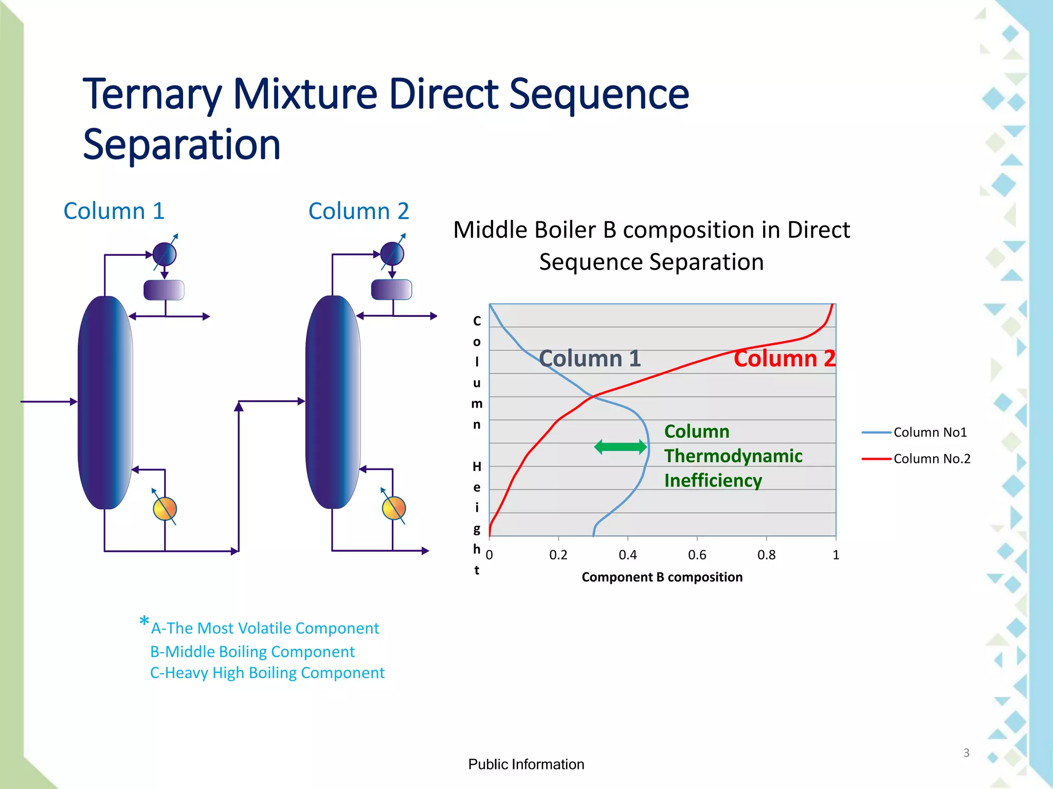
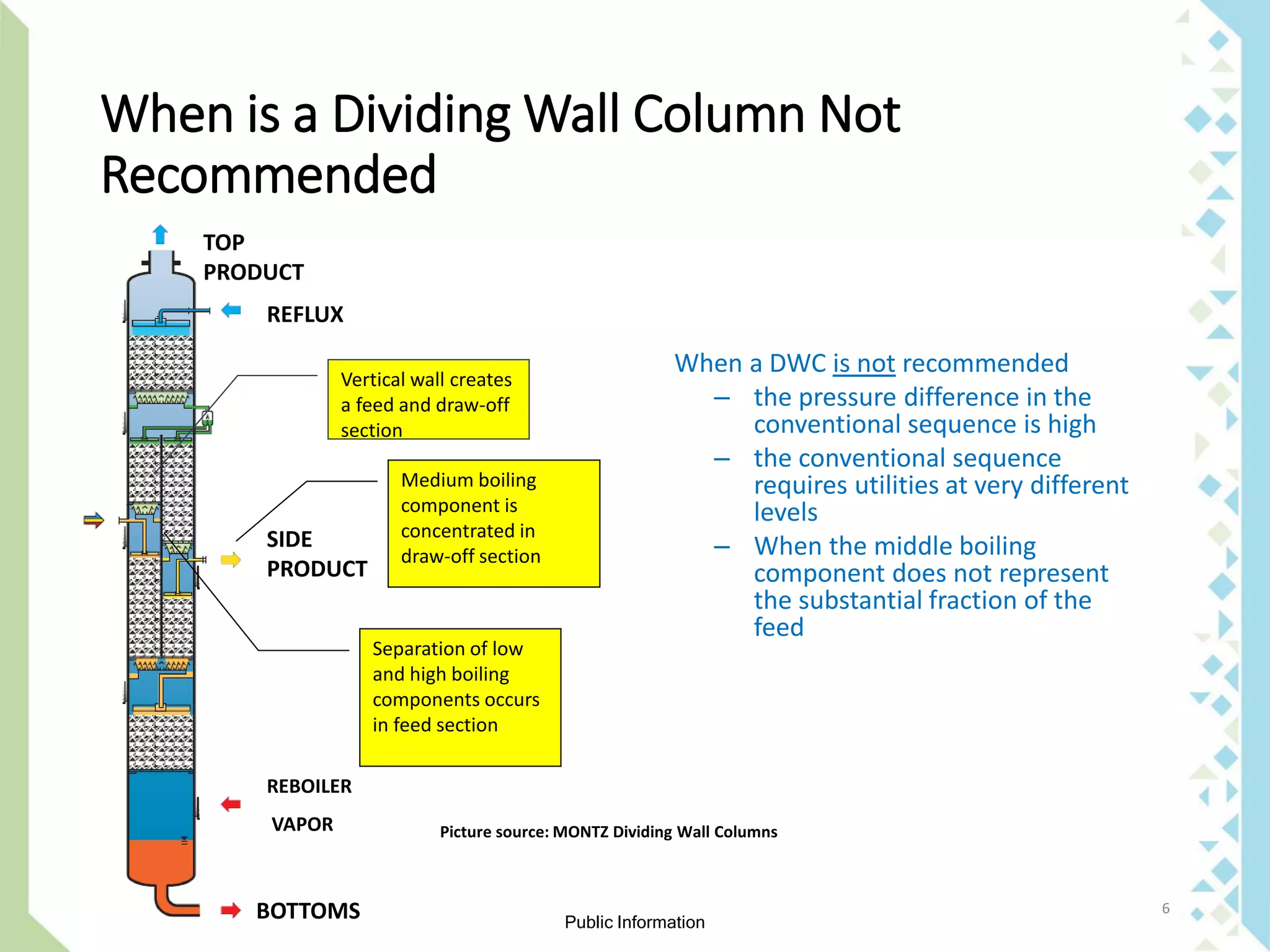
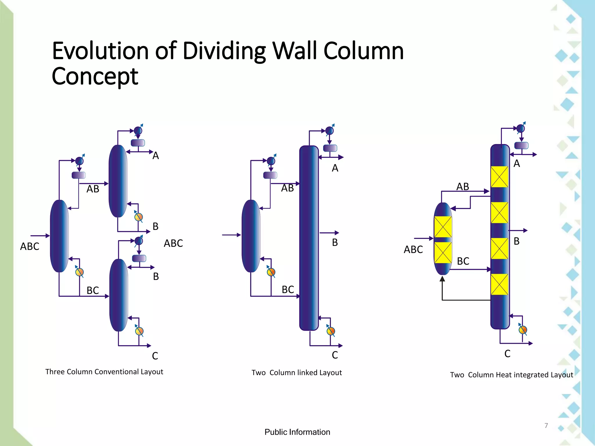
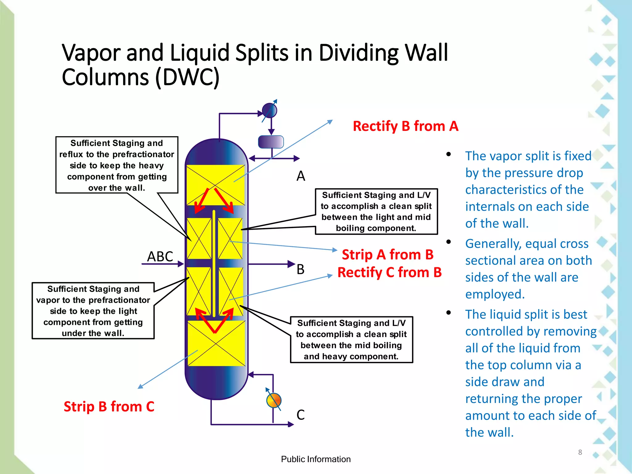
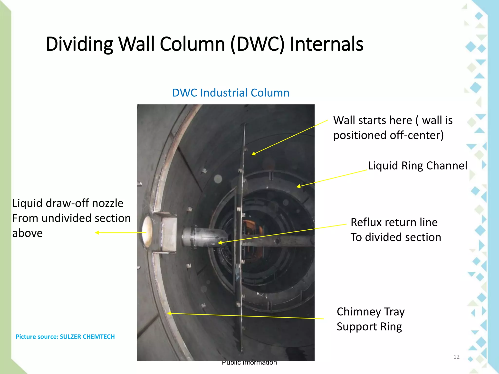
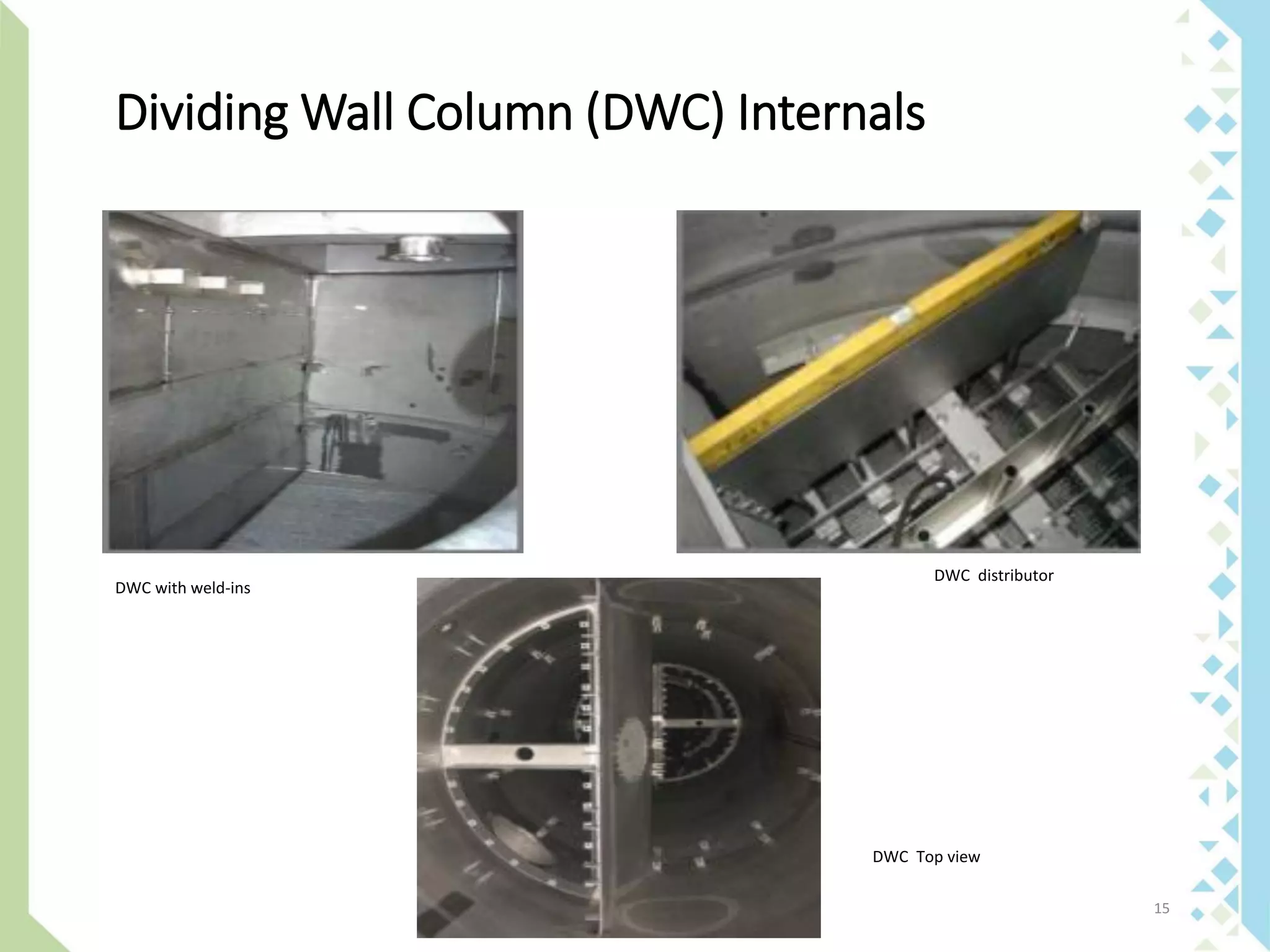
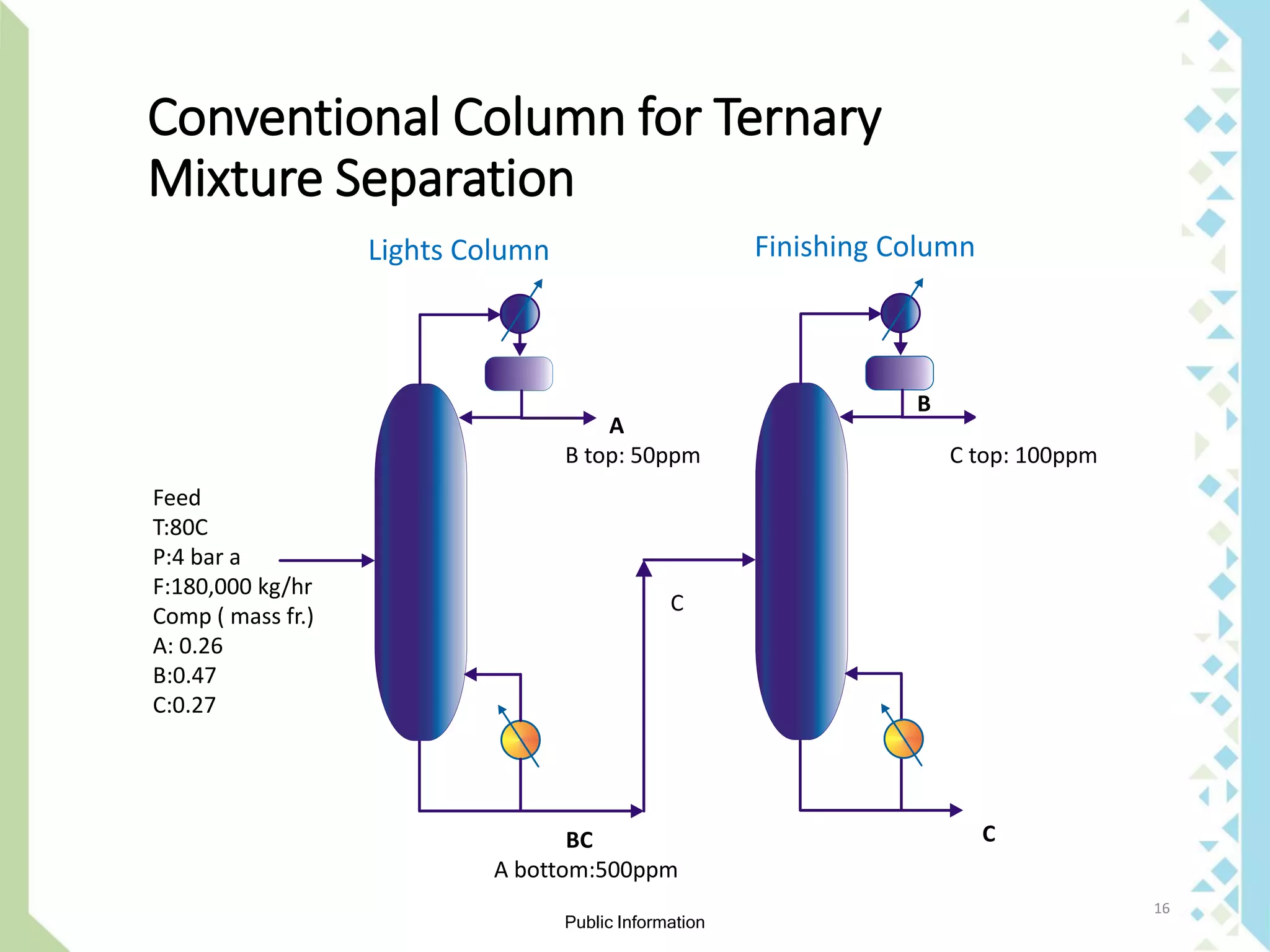
Public Information
Divide Your Distillation Column with
Confidence
Anup Elias & Petar Pribic
Sadara Chemical Company
October 2017
1
Anup Elias ( Speaker)
Public Information
2
Outline - Dividing Wall Column
➢ Understanding what is a Dividing Wall Column
➢ When to use a Dividing Wall Column
➢ Limitations in using a Dividing Wall Column
➢ Modeling a Dividing wall column
➢ Benefits of using a Dividing wall column vs
conventional column
➢ Inspection of Dividing Wall Column internals
Public Information
3
Ternary Mixture Direct Sequence
Separation
*A-The Most Volatile Component
B-Middle Boiling Component
C-Heavy High Boiling Component
Column 1 Column 2
0 0.2 0.4 0.6 0.8 1
C
o
l
u
m
n
H
e
i
g
h
t Component B composition
Middle Boiler B composition in Direct
Sequence Separation
Column No1
Column No.2
Column 1 Column 2
Column
Thermodynamic
Inefficiency
Public Information
4
What is a Dividing Wall Column
4
FEED
TOP
PRODUCT
REFLUX
SIDE
PRODUCT
REBOILER
VAPOR
Vertical wall creates
a feed and draw-off
section
Separation of low
and high boiling
components occurs
in feed section
Medium boiling
component is
concentrated in
draw-off section
BOTTOMS
Dividing Wall Column
Allows separation of 3 component mixture
into pure fractions in single column versus
conventional process with 2 sequential
columns
Particularly suited to obtain pure medium
boiling components
Picture source: MONTZ Dividing Wall Columns
Public Information
5
What is a Dividing Wall Column
FEED
TOP
PRODUCT
REFLUX
SIDE
PRODUCT
REBOILER
VAPOR
Vertical wall creates
a feed and draw-off
section
Separation of low
and high boiling
components occurs
in feed section
Medium boiling
component is
concentrated in
draw-off section
BOTTOMS
Dividing Wall Column
Allows separation of 3 component mixture
into pure fractions in single column versus
conventional process with 2 sequential
columns
Particularly suited to obtain pure medium
boiling components
Picture source: MONTZ Dividing Wall Columns
Public Information
6
When is a Dividing Wall Column Not
Recommended
TOP
PRODUCT
REFLUX
SIDE
PRODUCT
REBOILER
VAPOR
Vertical wall creates
a feed and draw-off
section
Separation of low
and high boiling
components occurs
in feed section
Medium boiling
component is
concentrated in
draw-off section
BOTTOMS
When a DWC is not recommended
– the pressure difference in the
conventional sequence is high
– the conventional sequence
requires utilities at very different
levels
– When the middle boiling
component does not represent
the substantial fraction of the
feed
Picture source: MONTZ Dividing Wall Columns
Public Information
7
ABC
AB
A
B
B
C
BC
ABC
AB
BC
C
B
A
ABC
BC
AB
A
B
C
Evolution of Dividing Wall Column
Concept
Three Column Conventional Layout Two Column linked Layout Two Column Heat integrated Layout
Public Information
8
Vapor and Liquid Splits in Dividing Wall
Columns (DWC)
ABC
A
B
C
Sufficient Staging and
reflux to the prefractionator
side to keep the heavy
component from getting
over the wall.
Sufficient Staging and
vapor to the prefractionator
side to keep the light
component from getting
under the wall.
Sufficient Staging and L/V
to accomplish a clean split
between the light and mid
boiling component.
Sufficient Staging and L/V
to accomplish a clean split
between the mid boiling
and heavy component.
• The vapor split is fixed
by the pressure drop
characteristics of the
internals on each side
of the wall.
• Generally, equal cross
sectional area on both
sides of the wall are
employed.
• The liquid split is best
controlled by removing
all of the liquid from
the top column via a
side draw and
returning the proper
amount to each side of
the wall.
Rectify B from A
Strip A from B
Rectify C from B
Strip B from C
Public Information
9
8 9
LIQTOSPL
TOP-PROD
14
17
FEED
10
13
16
11
MID-PROD
VAPTOSPL
BOT-PROD
TOP
MID-1
MID-2
BOT
SPL-LIQ
SPL-VAP
Rigorous Simulation
•4 RADFRAC Blocks
•2 Split Blocks
There are alternatives
•This seems the most intuitive
Getting Started
•Perform a 2-column sequence
•Arrange the simulation as seen
on the left with those numbers
•Optimize from there
DWC Rigorous Simulation
Public Information
10
Different DWC Layouts
Alpha A
Alpha B
> Alpha B
Alpha C
Alpha A
Alpha B
< Alpha B
Alpha C
Mb<<Ma,Mc Mb>>Ma,Mc
• Alpha-Relative Volatility
• M – Mass Flow rate
A
B
C
A
B
C
A
B
C
A
B
C
A-The Most Volatile Component
B-Middle Boiling Component
C-Heavy High Boiling Component
Public Information
11
Dividing Wall Column (DWC) Internals
Distributor
DWC Model Layout
Liquid
Collector
DWC Packing Fabrication
Picture source: SULZER CHEMTECH
Public Information
12
Dividing Wall Column (DWC) Internals
DWC Industrial Column
Wall starts here ( wall is
positioned off-center)
Liquid Ring Channel
Liquid draw-off nozzle
From undivided section
above
Chimney Tray
Support Ring
Reflux return line
To divided section
Picture source: SULZER CHEMTECH
Public Information
13
Dividing Wall Column (DWC) Internals
DWC with Trays
Off-center Partition Wall
Side Downcomers
( 2-Pass Trays)
Side Downcomers
( 2-Pass Trays)
Center Downcomer
( 2-Pass Trays) Tray weir
Clearance under DowncomerPicture source: SULZER CHEMTECH
Public Information
14
Dividing Wall Column (DWC) Internals
DWC with Middle Positioned Wall
(Distributor Layout)
Catalytic DWC
(Packing Filled with Catalyst))
Picture source: SULZER CHEMTECH
Public Information
15
Dividing Wall Column (DWC) Internals
DWC with weld-ins
DWC distributor
DWC Top view
Public Information
16
C
B
Feed
T:80C
P:4 bar a
F:180,000 kg/hr
Comp ( mass fr.)
A: 0.26
B:0.47
C:0.27
A
B top: 50ppm
BC
A bottom:500ppm
Lights Column Finishing Column
C
C top: 100ppm
Conventional Column for Ternary
Mixture Separation
Public Information
17
Composition Profile in Conventional
Column
Lights Column Composition Profile
Column
Bottoms
Column
Top
Component A
Component B
Component(s) C
Re - Mixing
CONCENTRATION
COLUMN HEIGHT
Public Information
18
Hydraulic Design
Lights Column
Upper Diameter,m:4.2m
Lower Diameter,m:4.5m
Packing: High Efficiency,250m2/m3
Upper Section: 2 Beds ( 4.1m/4.1m)
Bottom Section:2 Beds( 4.1m/3.1m)
Reboiler Duty, kW: 17,950
Finishing Column
Upper Diameter,m:3.9m
Lower Diameter,m:4.3m
Packing: High Efficiency,250m2/m3
Upper Section: 2 Beds ( 4.1m/3.6m)
Bottom Section:2 Beds ( 5.1m/5.1m)
Reboiler Duty,kW: 17,920
Lights Column Finishing Column
B top: 50ppm
BC
A bottom:500ppm
C top: 100ppm
B bottoms:
1000 ppm
Feed
Hydraulic Design of Conventional
Column
Public Information
19
Design of Dividing Wall Column (DWC)
DWC Rigorous Modelling
Pre-fractionator
Non-sharp split
Of middle boiling
component
No more mixing
inefficiency
Vapor split is determined
by wall position
Best Draw-off
Location
Liquid split is determined
by separation requirements
B top:50ppm
C in side Draw:100ppm
B bot:1000ppm
TOP
BOTTOM
FEED STAGE
Stage Number
(Top to Bottom)
Draw-off
LiquidProduct
Concentration
Public Information
20
Hydraulic calculations in DWC
Vapor Split – By Hydraulic Calculation of Internals
Prefractionator
Equivalent
Diameter
Pressure Drop
Upper Section
Pressure Drop
Lower Section
Wall Split: 60:40
Total Pressure Drop: 9.22mbar
Public Information
21
Hydraulic calculations in DWC
Vapor Split – By Hydraulic Calculation of Internals
Product Side
Equivalent
Diameter
Pressure Drop
Upper Section
Pressure Drop
Lower Section
Wall Split: 60:40
Total Pressure Drop: 9.15 mbar
Public Information
22
Hydraulic calculations in DWC
Rectification Section
Full
Diameter
Stripping Section
Full
Diameter
Public Information
23
Inspection of Dividing Wall Column (DWC)
Proper Column Inspection
Collars in packing
Proper Packing Installation
Importance of leveling
Improper bolting
Missing Tray Valves
Packing Support Grid
Level checking
Public Information
24
Conclusion
➢ Dividing wall columns are an alternative to multi-
column circuits, which reduces
• Investment
• Energy consumption,
• Plot area
• operational and maintenance costs.
➢ In our case, investment costs were reduced by 28 %
and utility costs were reduced by 24 %.
Public Information
Q & A
Thank you for your attention

Divide your distillation column with confidence

  • 1.
    Public Information Divide YourDistillation Column with Confidence Anup Elias & Petar Pribic Sadara Chemical Company October 2017 1 Anup Elias ( Speaker)
  • 2.
    Public Information 2 Outline -Dividing Wall Column ➢ Understanding what is a Dividing Wall Column ➢ When to use a Dividing Wall Column ➢ Limitations in using a Dividing Wall Column ➢ Modeling a Dividing wall column ➢ Benefits of using a Dividing wall column vs conventional column ➢ Inspection of Dividing Wall Column internals
  • 3.
    Public Information 3 Ternary MixtureDirect Sequence Separation *A-The Most Volatile Component B-Middle Boiling Component C-Heavy High Boiling Component Column 1 Column 2 0 0.2 0.4 0.6 0.8 1 C o l u m n H e i g h t Component B composition Middle Boiler B composition in Direct Sequence Separation Column No1 Column No.2 Column 1 Column 2 Column Thermodynamic Inefficiency
  • 4.
    Public Information 4 What isa Dividing Wall Column 4 FEED TOP PRODUCT REFLUX SIDE PRODUCT REBOILER VAPOR Vertical wall creates a feed and draw-off section Separation of low and high boiling components occurs in feed section Medium boiling component is concentrated in draw-off section BOTTOMS Dividing Wall Column Allows separation of 3 component mixture into pure fractions in single column versus conventional process with 2 sequential columns Particularly suited to obtain pure medium boiling components Picture source: MONTZ Dividing Wall Columns
  • 5.
    Public Information 5 What isa Dividing Wall Column FEED TOP PRODUCT REFLUX SIDE PRODUCT REBOILER VAPOR Vertical wall creates a feed and draw-off section Separation of low and high boiling components occurs in feed section Medium boiling component is concentrated in draw-off section BOTTOMS Dividing Wall Column Allows separation of 3 component mixture into pure fractions in single column versus conventional process with 2 sequential columns Particularly suited to obtain pure medium boiling components Picture source: MONTZ Dividing Wall Columns
  • 6.
    Public Information 6 When isa Dividing Wall Column Not Recommended TOP PRODUCT REFLUX SIDE PRODUCT REBOILER VAPOR Vertical wall creates a feed and draw-off section Separation of low and high boiling components occurs in feed section Medium boiling component is concentrated in draw-off section BOTTOMS When a DWC is not recommended – the pressure difference in the conventional sequence is high – the conventional sequence requires utilities at very different levels – When the middle boiling component does not represent the substantial fraction of the feed Picture source: MONTZ Dividing Wall Columns
  • 7.
    Public Information 7 ABC AB A B B C BC ABC AB BC C B A ABC BC AB A B C Evolution ofDividing Wall Column Concept Three Column Conventional Layout Two Column linked Layout Two Column Heat integrated Layout
  • 8.
    Public Information 8 Vapor andLiquid Splits in Dividing Wall Columns (DWC) ABC A B C Sufficient Staging and reflux to the prefractionator side to keep the heavy component from getting over the wall. Sufficient Staging and vapor to the prefractionator side to keep the light component from getting under the wall. Sufficient Staging and L/V to accomplish a clean split between the light and mid boiling component. Sufficient Staging and L/V to accomplish a clean split between the mid boiling and heavy component. • The vapor split is fixed by the pressure drop characteristics of the internals on each side of the wall. • Generally, equal cross sectional area on both sides of the wall are employed. • The liquid split is best controlled by removing all of the liquid from the top column via a side draw and returning the proper amount to each side of the wall. Rectify B from A Strip A from B Rectify C from B Strip B from C
  • 9.
    Public Information 9 8 9 LIQTOSPL TOP-PROD 14 17 FEED 10 13 16 11 MID-PROD VAPTOSPL BOT-PROD TOP MID-1 MID-2 BOT SPL-LIQ SPL-VAP RigorousSimulation •4 RADFRAC Blocks •2 Split Blocks There are alternatives •This seems the most intuitive Getting Started •Perform a 2-column sequence •Arrange the simulation as seen on the left with those numbers •Optimize from there DWC Rigorous Simulation
  • 10.
    Public Information 10 Different DWCLayouts Alpha A Alpha B > Alpha B Alpha C Alpha A Alpha B < Alpha B Alpha C Mb<<Ma,Mc Mb>>Ma,Mc • Alpha-Relative Volatility • M – Mass Flow rate A B C A B C A B C A B C A-The Most Volatile Component B-Middle Boiling Component C-Heavy High Boiling Component
  • 11.
    Public Information 11 Dividing WallColumn (DWC) Internals Distributor DWC Model Layout Liquid Collector DWC Packing Fabrication Picture source: SULZER CHEMTECH
  • 12.
    Public Information 12 Dividing WallColumn (DWC) Internals DWC Industrial Column Wall starts here ( wall is positioned off-center) Liquid Ring Channel Liquid draw-off nozzle From undivided section above Chimney Tray Support Ring Reflux return line To divided section Picture source: SULZER CHEMTECH
  • 13.
    Public Information 13 Dividing WallColumn (DWC) Internals DWC with Trays Off-center Partition Wall Side Downcomers ( 2-Pass Trays) Side Downcomers ( 2-Pass Trays) Center Downcomer ( 2-Pass Trays) Tray weir Clearance under DowncomerPicture source: SULZER CHEMTECH
  • 14.
    Public Information 14 Dividing WallColumn (DWC) Internals DWC with Middle Positioned Wall (Distributor Layout) Catalytic DWC (Packing Filled with Catalyst)) Picture source: SULZER CHEMTECH
  • 15.
    Public Information 15 Dividing WallColumn (DWC) Internals DWC with weld-ins DWC distributor DWC Top view
  • 16.
    Public Information 16 C B Feed T:80C P:4 bara F:180,000 kg/hr Comp ( mass fr.) A: 0.26 B:0.47 C:0.27 A B top: 50ppm BC A bottom:500ppm Lights Column Finishing Column C C top: 100ppm Conventional Column for Ternary Mixture Separation
  • 17.
    Public Information 17 Composition Profilein Conventional Column Lights Column Composition Profile Column Bottoms Column Top Component A Component B Component(s) C Re - Mixing CONCENTRATION COLUMN HEIGHT
  • 18.
    Public Information 18 Hydraulic Design LightsColumn Upper Diameter,m:4.2m Lower Diameter,m:4.5m Packing: High Efficiency,250m2/m3 Upper Section: 2 Beds ( 4.1m/4.1m) Bottom Section:2 Beds( 4.1m/3.1m) Reboiler Duty, kW: 17,950 Finishing Column Upper Diameter,m:3.9m Lower Diameter,m:4.3m Packing: High Efficiency,250m2/m3 Upper Section: 2 Beds ( 4.1m/3.6m) Bottom Section:2 Beds ( 5.1m/5.1m) Reboiler Duty,kW: 17,920 Lights Column Finishing Column B top: 50ppm BC A bottom:500ppm C top: 100ppm B bottoms: 1000 ppm Feed Hydraulic Design of Conventional Column
  • 19.
    Public Information 19 Design ofDividing Wall Column (DWC) DWC Rigorous Modelling Pre-fractionator Non-sharp split Of middle boiling component No more mixing inefficiency Vapor split is determined by wall position Best Draw-off Location Liquid split is determined by separation requirements B top:50ppm C in side Draw:100ppm B bot:1000ppm TOP BOTTOM FEED STAGE Stage Number (Top to Bottom) Draw-off LiquidProduct Concentration
  • 20.
    Public Information 20 Hydraulic calculationsin DWC Vapor Split – By Hydraulic Calculation of Internals Prefractionator Equivalent Diameter Pressure Drop Upper Section Pressure Drop Lower Section Wall Split: 60:40 Total Pressure Drop: 9.22mbar
  • 21.
    Public Information 21 Hydraulic calculationsin DWC Vapor Split – By Hydraulic Calculation of Internals Product Side Equivalent Diameter Pressure Drop Upper Section Pressure Drop Lower Section Wall Split: 60:40 Total Pressure Drop: 9.15 mbar
  • 22.
    Public Information 22 Hydraulic calculationsin DWC Rectification Section Full Diameter Stripping Section Full Diameter
  • 23.
    Public Information 23 Inspection ofDividing Wall Column (DWC) Proper Column Inspection Collars in packing Proper Packing Installation Importance of leveling Improper bolting Missing Tray Valves Packing Support Grid Level checking
  • 24.
    Public Information 24 Conclusion ➢ Dividingwall columns are an alternative to multi- column circuits, which reduces • Investment • Energy consumption, • Plot area • operational and maintenance costs. ➢ In our case, investment costs were reduced by 28 % and utility costs were reduced by 24 %.
  • 25.
    Public Information Q &A Thank you for your attention