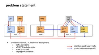
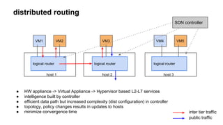
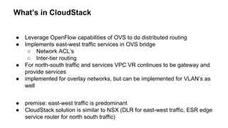
CloudStack: Distributed routing and ACL’s with SDN
problem statement 
VM1 
VM2 
VM3 
● problems with VPC in traditional deployment 
○ traffic trombone 
○ VPC VR is choke point 
○ scale up model 
○ single point of failure 
Blue 
tier 
bridge 
Orange 
tier 
bridge 
Orange 
tier 
bridge 
Blue 
tier 
bridge 
Orange 
tier 
bridge 
VPC 
VR 
Public 
traffic 
bridge 
inter tier (east-west) traffic 
public (north-south) traffic 
host 1 host 2 host 3
distributed routing 
VM1 
logical router 
VM2 VM3 
SDN controller 
VM4 VM5 
logical router logical router 
host 1 host 2 host 3 
● HW appliance -> Virtual Appliance -> Hypervisor based L2-L7 services 
● intelligence built by controller 
● efficient data path but increased complexity (dist configuration) in controller 
● topology, policy changes results in updates to hosts 
● minimize convergence time 
inter tier traffic 
public traffic
distributed routing (contd..) 
● SDN controllers implementing distributed routing 
○ Vmware NSX 
○ Hyper-V HNV 
○ Midokura 
○ Contrail
What’s in CloudStack 
● Leverage OpenFlow capabilities of OVS to do distributed routing 
● Implements east-west traffic services in OVS bridge 
○ Network ACL’s 
○ Inter-tier routing 
● For north-south traffic and services VPC VR continues to be gateway and 
provide services 
● implemented for overlay networks, but can be implemented for VLAN’s as 
well 
● premise: east-west traffic is predominant 
● CloudStack solution is similar to NSX (DLR for east-west traffic, ESR edge 
service router for north south traffic)
CloudStack - distributed routing 
VM1 
VM2 VM3 
logical router 
(OVS bridge) 
VPC 
VR 
VM4 VM5 
logical router 
(OVS bridge) 
logical router 
(OVS bridge) 
host 1 host 2 host 3 
SDN controller 
in 
CloudStack 
● OVS bridge configured to act as logical router, performing 
○ ingress/egress ACL 
○ Inter tier routing 
○ L2 switching 
● single bridge for all VPC tiers 
● bridge no a longer learn-flood switch, data path is software (CloudStack controller) defined
CloudStack traditional VPC inter-tier packet flow 
VM2 
● Sequence of action for packet flow from VM1 to VM2 
VPC 
VR 
○ ARP request for gateway 10.1.1.1 
○ ARP response for 10.1.1.1 
○ packet sent to gateway (src MAC = VM1’s mac, dst MAC = source subnet gateway mac, src IP = VM1 ip, 
dst IP = VM2 IP) 
○ packet routed by VPC VR and sent on destination subnet after modifying packet (src MAC = destination 
subnet gateway mac, dst MAC =VM2 mac, src IP = VM1 ip, dst IP = VM2 IP) 
VM1 
Blue 
tier bridge 
Orange 
tier 
bridge 
Blue 
tier bridge 
Orange 
tier bridge 
host 1 host 2 
1 
2 1 
2 3 
3 
4 4
logical router - packet flow 
B/M 
traffic 
L2 switching 
L2 Flooding 
From 
tunnel 
port 
no 
Egress ACL 
yes 
Inter-tier 
traffic 
IP outort 
IP outport 
IP outport 
Drop Looku 
p hit 
Drop 
yes 
L3 lookup Ingress ACL 
Flow action 
Flow action 
Flow action 
yes 
no 
yes 
no 
yes 
no 
IP outort 
IP outport 
IP outport 
Flow action 
Flow action 
Flow action 
yes 
no 
Looku 
p hit 
inport outorts 
inport outorts 
inport outorts 
yes 
send on 
outport/outports 
no 
no 
Modify 
packet
OpenFlow - pipeline processing 
Matching fields Action Counters 
● Pipeline processing : OpenFlow abstractions to build complex packet processing logic
OVS bridge- logical router- pipeline processing 
How does CloudStack controller populate forwarding tables?
Populating L2,L3 lookup and ACL tables 
● management server has the knowledge 
○ Hosts on which VPC spans 
○ tiers in the VPC 
○ VM in each tier and corresponding IP address of the NIC 
○ gateway and CIDR of each tier 
○ routing policies (ingress & egress ACL’s) 
● management server orchestrates 
○ VM Start, Stop, Migrate 
○ tier create, destroy etc 
○ network ACL replaced 
● for each change that affects VPC topology and routing policies triggers the update to OpenFlow 
tables based on the latest info 
● Agent commands 
○ OvsVpcRoutingPolicyConfigCommand 
○ OvsVpcPhysicalTopologyConfigCommand
OvsVpcPhysicalTopologyConfigCommand 
● For each change in VPC topology controller sends 
JSON representation of VPC topology to each host 
● each host process topology to form the knowledge of 
○ a MAC is reachable through which VIF/tunnel port 
○ an IP address is required packet modification 
needed to route the packet
OvsVpcRoutingPolicyConfigCommand 
● For each change in Network ACL associated with a tier 
in VPC, controller sends JSON representation of VPC 
routing policies to each host 
● each host process routing policies to add flow rules to 
permit/deny flows
Sync mechanism 
● On host reconnect 
○ send physical topology update for each VPC spanned on the host 
○ send routing policies update for each VPC spanned on the host 
● periodic updates

Distributed routing

  • 1.
    CloudStack: Distributed routingand ACL’s with SDN
  • 2.
    problem statement VM1 VM2 VM3 ● problems with VPC in traditional deployment ○ traffic trombone ○ VPC VR is choke point ○ scale up model ○ single point of failure Blue tier bridge Orange tier bridge Orange tier bridge Blue tier bridge Orange tier bridge VPC VR Public traffic bridge inter tier (east-west) traffic public (north-south) traffic host 1 host 2 host 3
  • 3.
    distributed routing VM1 logical router VM2 VM3 SDN controller VM4 VM5 logical router logical router host 1 host 2 host 3 ● HW appliance -> Virtual Appliance -> Hypervisor based L2-L7 services ● intelligence built by controller ● efficient data path but increased complexity (dist configuration) in controller ● topology, policy changes results in updates to hosts ● minimize convergence time inter tier traffic public traffic
  • 4.
    distributed routing (contd..) ● SDN controllers implementing distributed routing ○ Vmware NSX ○ Hyper-V HNV ○ Midokura ○ Contrail
  • 5.
    What’s in CloudStack ● Leverage OpenFlow capabilities of OVS to do distributed routing ● Implements east-west traffic services in OVS bridge ○ Network ACL’s ○ Inter-tier routing ● For north-south traffic and services VPC VR continues to be gateway and provide services ● implemented for overlay networks, but can be implemented for VLAN’s as well ● premise: east-west traffic is predominant ● CloudStack solution is similar to NSX (DLR for east-west traffic, ESR edge service router for north south traffic)
  • 6.
    CloudStack - distributedrouting VM1 VM2 VM3 logical router (OVS bridge) VPC VR VM4 VM5 logical router (OVS bridge) logical router (OVS bridge) host 1 host 2 host 3 SDN controller in CloudStack ● OVS bridge configured to act as logical router, performing ○ ingress/egress ACL ○ Inter tier routing ○ L2 switching ● single bridge for all VPC tiers ● bridge no a longer learn-flood switch, data path is software (CloudStack controller) defined
  • 7.
    CloudStack traditional VPCinter-tier packet flow VM2 ● Sequence of action for packet flow from VM1 to VM2 VPC VR ○ ARP request for gateway 10.1.1.1 ○ ARP response for 10.1.1.1 ○ packet sent to gateway (src MAC = VM1’s mac, dst MAC = source subnet gateway mac, src IP = VM1 ip, dst IP = VM2 IP) ○ packet routed by VPC VR and sent on destination subnet after modifying packet (src MAC = destination subnet gateway mac, dst MAC =VM2 mac, src IP = VM1 ip, dst IP = VM2 IP) VM1 Blue tier bridge Orange tier bridge Blue tier bridge Orange tier bridge host 1 host 2 1 2 1 2 3 3 4 4
  • 8.
    logical router -packet flow B/M traffic L2 switching L2 Flooding From tunnel port no Egress ACL yes Inter-tier traffic IP outort IP outport IP outport Drop Looku p hit Drop yes L3 lookup Ingress ACL Flow action Flow action Flow action yes no yes no yes no IP outort IP outport IP outport Flow action Flow action Flow action yes no Looku p hit inport outorts inport outorts inport outorts yes send on outport/outports no no Modify packet
  • 9.
    OpenFlow - pipelineprocessing Matching fields Action Counters ● Pipeline processing : OpenFlow abstractions to build complex packet processing logic
  • 10.
    OVS bridge- logicalrouter- pipeline processing How does CloudStack controller populate forwarding tables?
  • 11.
    Populating L2,L3 lookupand ACL tables ● management server has the knowledge ○ Hosts on which VPC spans ○ tiers in the VPC ○ VM in each tier and corresponding IP address of the NIC ○ gateway and CIDR of each tier ○ routing policies (ingress & egress ACL’s) ● management server orchestrates ○ VM Start, Stop, Migrate ○ tier create, destroy etc ○ network ACL replaced ● for each change that affects VPC topology and routing policies triggers the update to OpenFlow tables based on the latest info ● Agent commands ○ OvsVpcRoutingPolicyConfigCommand ○ OvsVpcPhysicalTopologyConfigCommand
  • 12.
    OvsVpcPhysicalTopologyConfigCommand ● Foreach change in VPC topology controller sends JSON representation of VPC topology to each host ● each host process topology to form the knowledge of ○ a MAC is reachable through which VIF/tunnel port ○ an IP address is required packet modification needed to route the packet
  • 13.
    OvsVpcRoutingPolicyConfigCommand ● Foreach change in Network ACL associated with a tier in VPC, controller sends JSON representation of VPC routing policies to each host ● each host process routing policies to add flow rules to permit/deny flows
  • 14.
    Sync mechanism ●On host reconnect ○ send physical topology update for each VPC spanned on the host ○ send routing policies update for each VPC spanned on the host ● periodic updates