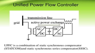
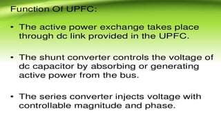
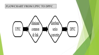
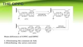
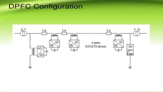
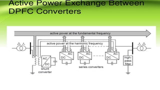
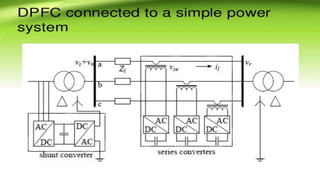
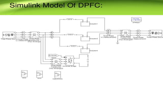
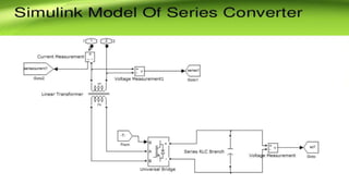
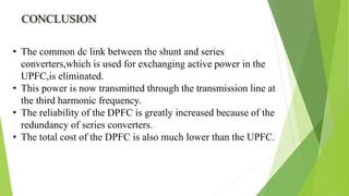
ANNAMACHARYA INSTITUTE OF TECHNOLOGY AND SCIENCES
POWER FLOW CONTROL THROUGH
DISTRIBUTED POWER FLOW CONTROLLER
PROJECT GUIDED BY:-
MRS R.M.DEEPTHI BHAI M.Tech PROJECT MEMBERS:
R.NARESH(14AK5A0211)
J.SUNDAR KUMAR(13AK1A0242)
C.MANISHANKAR(14AK5A0208)
N.KALYAN KUMAR(13AK1A0213)
P.SRIKANTH(12AK1A0247)
ABSTRACT
This project presents a new component within the flexible
ac-transmission system (FACTS) family, called distributed
power-flow controller (DPFC). The DPFC is derived from the unified
power-flow controller (UPFC). TheDPFC can be considered as
a UPFC with an eliminated common dc link. The active power exchange
between the shunt and series converters, which is through
the common dc link in the UPFC, is now through the transmission
lines at the third-harmonic frequency. The DPFC employs
the distributed FACTS (D-FACTS) concept, which is to use multiple
small-size single-phase converters instead of the one large-size
three-phase series converter in the UPFC. The large number of
series converters provides redundancy, thereby increasing the system
reliability. As the D-FACTS converters are single-phase and
floating with respect to the ground, there is no high-voltage isolation
required between the phases. Accordingly, the cost of the
DPFC system is lower than the UPFC. The DPFC has the same
control capability as the UPFC, which comprises the adjustment
of the line impedance, the transmission angle, and the bus voltage.
OUTLINES
 Objectives.
 Introduction.
 UPFC Controller.
 Function of UPFC.
 Flow chart from UPFC to DPFC.
 The DPFC.
 DPFC Configuration.
 Active power exchange between DPFC converters.
 Operation of DPFC
 DPFC CONTROL Scheme.
 DPFC Advantages.
 Simulink of DPFC.
 Conclusion.
OBJECTIVES
 To compensate reactive power in
transmission line.
 To overcome the disadvantages of Unified
Power Flow Controller(UPFC).
INTRODUCTION
The main purpose of this technology is to control and regulate
the electrical variables in the power systems.Basically the family
of FACTS devices based on voltage source converters (VSCs)
consists of a series compensator, and current sorce converters
(CSCs) consists of a shunt compensator.The UPFC is not widely
applied in practice, due to their high cost and the susceptibility
to failures.
Generally, the reliability can be improved by reducing the
number of components.DPFC has two major advantages:1)low
cost because of low voltage isolation and low rating of series
converter and 2)High reliability because of the redundancy of
series converters
FLOWCHART FROM UPFC TO DPFC
CONCLUSION
• The common dc link between the shunt and series
converters,which is used for exchanging active power in the
UPFC,is eliminated.
• This power is now transmitted through the transmission line at
the third harmonic frequency.
• The reliability of the DPFC is greatly increased because of the
redundancy of series converters.
• The total cost of the DPFC is also much lower than the UPFC.
THANK YOU

Distributed power flow controller (naresh)

  • 1.
    ANNAMACHARYA INSTITUTE OFTECHNOLOGY AND SCIENCES POWER FLOW CONTROL THROUGH DISTRIBUTED POWER FLOW CONTROLLER PROJECT GUIDED BY:- MRS R.M.DEEPTHI BHAI M.Tech PROJECT MEMBERS: R.NARESH(14AK5A0211) J.SUNDAR KUMAR(13AK1A0242) C.MANISHANKAR(14AK5A0208) N.KALYAN KUMAR(13AK1A0213) P.SRIKANTH(12AK1A0247)
  • 2.
    ABSTRACT This project presentsa new component within the flexible ac-transmission system (FACTS) family, called distributed power-flow controller (DPFC). The DPFC is derived from the unified power-flow controller (UPFC). TheDPFC can be considered as a UPFC with an eliminated common dc link. The active power exchange between the shunt and series converters, which is through the common dc link in the UPFC, is now through the transmission lines at the third-harmonic frequency. The DPFC employs the distributed FACTS (D-FACTS) concept, which is to use multiple small-size single-phase converters instead of the one large-size three-phase series converter in the UPFC. The large number of series converters provides redundancy, thereby increasing the system reliability. As the D-FACTS converters are single-phase and floating with respect to the ground, there is no high-voltage isolation required between the phases. Accordingly, the cost of the DPFC system is lower than the UPFC. The DPFC has the same control capability as the UPFC, which comprises the adjustment of the line impedance, the transmission angle, and the bus voltage.
  • 3.
    OUTLINES  Objectives.  Introduction. UPFC Controller.  Function of UPFC.  Flow chart from UPFC to DPFC.  The DPFC.  DPFC Configuration.  Active power exchange between DPFC converters.  Operation of DPFC  DPFC CONTROL Scheme.  DPFC Advantages.  Simulink of DPFC.  Conclusion.
  • 4.
    OBJECTIVES  To compensatereactive power in transmission line.  To overcome the disadvantages of Unified Power Flow Controller(UPFC).
  • 5.
    INTRODUCTION The main purposeof this technology is to control and regulate the electrical variables in the power systems.Basically the family of FACTS devices based on voltage source converters (VSCs) consists of a series compensator, and current sorce converters (CSCs) consists of a shunt compensator.The UPFC is not widely applied in practice, due to their high cost and the susceptibility to failures. Generally, the reliability can be improved by reducing the number of components.DPFC has two major advantages:1)low cost because of low voltage isolation and low rating of series converter and 2)High reliability because of the redundancy of series converters
  • 8.
  • 19.
    CONCLUSION • The commondc link between the shunt and series converters,which is used for exchanging active power in the UPFC,is eliminated. • This power is now transmitted through the transmission line at the third harmonic frequency. • The reliability of the DPFC is greatly increased because of the redundancy of series converters. • The total cost of the DPFC is also much lower than the UPFC.
  • 20.