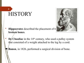
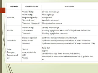
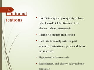
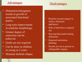
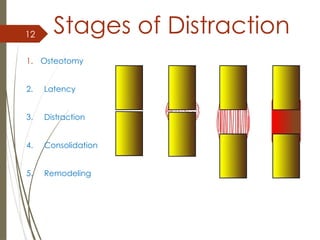
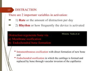
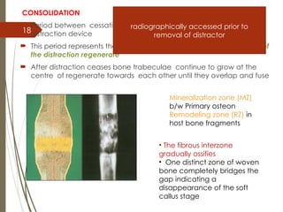
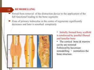
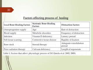
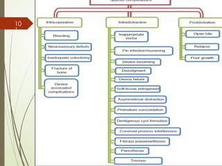
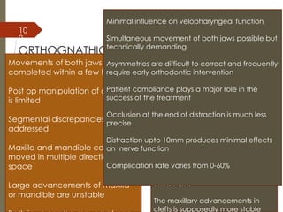
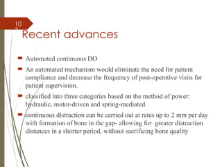
1
DISTRACTION
OSTEOGENESIS
JIJY JAMES
III MDS
MODERATOR: Dr. VARSHA UPADYA
2
CONTENTS
 Introduction
 History
 Biological basis of new bone formation
 Distraction osteogenesis
 Distraction histiogenesis
 Classification of D. O devices
 Mandibular DO
 Maxillary DO
 Midface DO
 Craniofacial DO
 Alveolar distraction
 Transport DO
 Complication
 Conclusion
3
INTRODUCTION
Definition-A biological process of new
bone formation between the surfaces of
an osteotomized bone segments that
are gradually separated by incremental
traction.
 This process begins when a traction
force is applied to the bone segments,
creating a tensional stress in a
reparative callus˘- callotasis
 Tension in the surrounding soft tissues
initiating a sequence of adaptive
changes  Distraction Histiogenesis
4
HISTORY
• Hippocrates described the placement of traction forces on
broken bones.
• De Chauliac in the 14th
century, who used a pulley system
that consisted of a weight attached to the leg by a cord.
 Banon, in 1826, performed a surgical division of bone.
5
 Codivilla combined these techniques to perform the first limb
lengthening using external skeletal traction after an oblique
osteotomy of the femur.
 Kazanjian 1937 –performed mandibular osteodistraction with
incremental traction
 Significant contributions were made by the Russian surgeon
Gavriel Ilizarov 1951
 Iilizarov discovered 2 biological principles of distraction
osteogenesis known as Iilizarov Effects.
a) Tension stress effect on genesis & growth of tissue.
b) Influence of blood supply and loading on shape of bone and
joints.
6Guerro (1990)- midsymphyseal mandibular widening technique
I/O tooth borne hyrax type devices
Maccarthy and colleagues 1992 -Extraoral devices for
craniofacial anomalies such as hemifacial microsomia , nager’s
syndrome
 Molina and ortiz- monasterio( 1995) -first to apply bidirectional
mandibular DO in Patients with mandibular microsomia or
micrognathia
 In 1995 Block et al - anterior maxillary advancement using tooth
borne distraction Devices
 1995 -First clinical application of midface distraction was
reported by polley et al
7 ILIZAROV PRINCIPLES:
OSTEOTOMY of the bone site with minimal periosteal stripping.
LATENCY After bone cut is performed, a latency period of 5 to 7 days is
observed before device activation
DISTRACTION- rate and rhythm
Rate: A regenerate can best be generated when the tensile stress is applied
and bone edges separated 1.0 mm per day
Rhythm: Continuous application of distraction force is ideal
CONSOLIDATION -Once the regenerate has been created, the distraction
device is held in neutral fixation allowing the new bone to ossify.
ILIZAROV’S CRITERIA
• Surgical procedure must involve minimum marrow damage;
hence corticotomy preferred.
• Fixity of the device: Rigid fixation is a must.
• Rate: 1 mm per day- optimal
• Rhythm: Optimum of 2-4 activations/day
8
Biologic
al basis
of new
bone
formatio
n
 After callus has formed traction force is
applied to these bone segments  which
gradually pushes them apart
 Gradual incremental separation of bone
segments places the callus under tensional
stress  aligns the newly formed inter-
segmentory tissue parallel to the direction of
traction
 After desired amount of lengthening is
achieved the distraction force is discontinued
and the newly formed bone ( distraction
regenerate ) undergoes maturation and
remodeling until it becomes no different from
residual bone
9
Indications
• Maxillary deficiency in CLP or
Craniosynostosis
• Post-traumatic growth disturbance
• Atrophy of edentulous segments
• Oncologic mandibular osseous defects
• Congenital syndromes
• Severe mandibular deficiency > 10-15
mm
• A short mandibular ramus
• A narrow, V-shape mandible
• TMJ ankylosis
• Obstructive sleep apnea
10
Contraind
ications
 Insufficient quantity or quality of bone
which would inhibit fixation of the
device such as osteoporosis
 Infants <6 months-fragile bone
 Inability to comply with the post
operative distraction regimen and follow
up schedule.
• Hypersensitivity to metals
• Radiotherapy and elderly-delayed bone
formation
11
• Distraction histogensis
results in growth of
associated functional
matrix.
• Long term improvement
in condylar morphology.
• Greater degree of
correction can be
achieved.
• Grafts are not required.
• Can be done in children
as young as 2 years.
• Minimal skeletal relapse.
Advantages Disdvantages
• Requires second surgery to
remove distractor
appliances
• Risk of infection at surgical
site
• Pain and discomfort during
distraction
• Required meticulous
planning
• Results are not as precise as
orthognathic surgery
12 Stages of Distraction
1. Osteotomy
2. Latency
3. Distraction
4. Consolidation
5. Remodeling
13
OSTEOTOMY
 Divides bone into two segments
 Loss of continuity & mechanical integrity
 Evolutionary process of bone repair similar to that observed
during fracture healing
LATENCY
 period from bone division to the onset of traction
 Following surgical separation  in growth of capillaries
 Cellular proliferation
 Stage of soft callus ( last for 3 weeks )
 Capillaries continues to grow into fracture callus  granulation
tissue & loose connective tissue are converted gradually to
fibrous & cartilaginous tissue
14
3. DISTRACTION
 During normal fracture healing the stage of soft callus is followed by stage
of hard callus ( last for 3 to 4 months )
 During distraction the normal process of fracture healing is interrupted by
application of gradual traction to the bone segments at the stage of the soft
callus
 This traction progressively separates the bone segments there by generating
tensional stress in the tissues of the forming soft callus & in the surrounding
soft tissues
 This results in increased proliferation of the fibroblastic cell population and
prolongation of angiogenesis with increased tissue oxygenation
 Fibrous tissue of the soft callus becomes longitudinally oriented in a
direction parallel to the axis of distraction
15
During this time the distraction regenerate has specific
zonal structures:
• FZ (Fibrous zone)-A poorly mineralized
zone, consisting of highly organized bundles
of collagen with spindle shaped fibroblasts
& undifferentiated mesenchymal cells.
• MZ (Mineralized zone)- Has
longitudinally oriented, Cylindrical
primary trabeculae, which are covered by
a layer of osteoblasts.
This zonal distribution of newly formed tissues in the
distraction regenerate remains until the end of the
distraction period.
16
 From second week of distraction the osteoblasts lay down osteoid
tissue on these longitudinally oriented collagen fibres and primary
bone trabeculae begins to form
Mineralization (MZ)-
longitudinally oriented primary
osteons
Fibrous radiolucent inter-zone
(FZ)-
longitudinally oriented
collagen bundles
End of second week osteoid begins to mineralize at that time,
distraction regenerate has specific three zonal structure ( simultaneously
representing a two stage of# healing  soft & hard callus
17 DISTRACTION
There are 2 important variables in activation:
 1) Rate or the amount of distraction per day
 2) Rhythm or how frequently the device is activated
Distraction regenerate bone via
a) Membrane ossification
b) Endochondral bone formation
Minoru Veda et al
 Intramembranous ossification with direct formation of new bone
and
 Endochondral ossification in which the cartilage is formed and
replaced by bone through vascular invasion of the capillaries
18
CONSOLIDATION
 Period between cessation of traction forces and removal of the
distraction device
 This period represents the time required for complete mineralization of
the distraction regenerate
 After distraction ceases bone trabeculae continue to grow at the
centre of regenerate towards each other until they overlap and fuse
Mineralization zone (MZ)
b/w Primary osteon
Remodeling zone (RZ) in
host bone fragments
• The fibrous interzone
gradually ossifies
• One distinct zone of woven
bone completely bridges the
gap indicating a
disappearance of the soft
callus stage
radiographically accessed prior to
removal of distractor
19 REMODELLING
 Period from removal of the distraction device to the application of the
full functional loading to the bone segments
 Zone of primary trabeculae in the centre of regenerate significantly
decreases and later is resorbed completely
• Initially formed bony scaffold
is reinforced by parallel fibered
and lamellar bone
• The cortical bone & marrow
cavity are restored
Followed by haversian
remodelling  normalizes the
bone structure
20
Factors affecting process of healing
21
DISTRACTION HISTIOGENESIS
 During distraction soft tissues are stretched with out any
surgical separation  D Histiogenesis
 Soft tissue adaptation to gradual streching
1. Soft tissue regeneration following disruptive & degenerative
changes
2. Neo Histiogenesis as a result of generalized cellular
proliferation & growth
22
SKELETAL
MUSCLES
 During D O increase in metabolic & synthetic
activities of the muscle
 When distraction forces are applied to the bone fibers
of the attached muscles undergo incremental gradual
stretching
 Stretching of the muscle fibers in turn stretches the
sarcomere  there by increasing their length
 Forcing the actin & myosin filaments to slide over
each other
 This diminishes the number of connecting bridges b/w
the two protein and finally compromises muscle
function
23
 Finally progressive distraction may over come the
resistance of the tissue resulting in local degenerative
and necrotic changes of muscle fiber followed by
separation of two parts of the muscle fibre
 Regenerative process occurs at the end of the ruptured
fibre
 Inflammatory cells immediately migrate to the site of
injury
 Satellite cells proliferate& migrate next providing a
new generation of myoblast  which fuses to form
new myofibrils
 Synthesis of myofibrillar proteins completes the
restoration of the injured muscle fibre
 Later rapid proliferation of fibroblastic cell population
24
EFFECT ON
PERIPHERAL
NERVES
 Mechanism of stretch injury and
adaptation of peripheral nerves to the
gradual distraction remains poorly
understood
 Finding suggest that gradual distraction
of the mandible within 10mm is a safe
limit of inferior alveolar nerve elongation
which produces potentially reversible
functional changes
 Constriction by narrowing of medullary
canal due to bone in-growth during
distraction can also cause damage
25
 Ilizarov described histological changes that occurred in a dogs
peroneal and tibial nerves during 50% limb lengthening.
 The first 15% was characterized by early changes of nerve fibers
with constriction of Schwann cells
 At 20% lengthening similar changes took place in un-myelinated
nerve fibres.
 Further 25-50% lengthening resulted in more pathological
changes. During consolidation, progressive regeneration of nerve
fibers was observed.
26
EFFECT
ON
GINGIVA
 Gradual stretching results in mild atrophic reactive
changes progressive restoration of normal anatomic
structure
 As DH proceeds the preexisting gingival tissues stretch
to accommodate the new length while maintaining
surface continuity
 As DO proceeds less mature cells in the basal layer
proliferate differentiation to reconstitute the
epithelial cell layers
 Stimulatory effects of tension in the soft tissue
increases the biosynthetic activities
 As tissue is stretched the mucoperiosteal attachment to
the alveolar bone may migrate over time to relieve the
27
EFFECT ON
PERIODONTAL
LIGAMENT
 During DO PDL is compressed on one side of the
tooth & stretched on the opposite side ˘
 The location of compression /tension sites and the
related sequence of adaptive changes depend on the
type of distraction device ( tooth borne or bone
borne ) & the location of the distraction forces
 Tooth borne distraction devices are attached directly
to the teeth there by transmitting distraction forces
from the teeth to the bone via the PDL
 During consolidation period PDL adapts to its new
position
 Bone resorption at the compression side & new
bone formation at the tension side
28
 In bone borne devices location of tension & compression sites
is opposite to the that during tooth borne distraction
 The initial tension / pressure stress’s that accumulated in the
stretched/ compressed periodontal ligament fibers activates
adaptive mechanism such as bone resorption , osteogenesis &
cemetogenesis restoring the equilibrium in length and tension
of the periodontal ligament
 Tooth borne distraction  grater dental moments than skeletal
movements so should be taken into consideration during pre-
operative planning
29 CLASSIFICATION
30
Extra oral distraction appliances
31
Internal Distraction appliances
Zurich Maxillary Distractor
( Lorenz)
32
UNIDIRECTIONAL
DISTRACTOR
33
BIDIRECTIONAL DISTRACTOR
34
MULTI -DIRECTIONAL DISTRACTOR
35
Planning
Detailed case history
Extraoral Examination
Intraoral Examination
Occlusion
Occlusal plane
Function
Maximum interincisal opening
Mandibular deviation or
deflection
TMJ evaluation
Sensory nerve function
36 Diagnostic Records
Standard extraoral and intraoral photographs
Dental models articulated on a semi-adjustable
articulator
Lateral and PA cephalograms
OPG
CBCT
CT Scan
Stereolithographic models
37
Treatment planning for mandibular distraction
 Distractor placement
according to the simple
formula
Pin placement angle =
180 – Gonial angle x Ramus
deficiency
Total deficiency
Where Pin placement angle = angle
between distraction vector and
mandibular plane
Later this formula was modified
Pin placement angle = Sin a
Db/Dr – Cos a
Where a = gonial angle
Db = corpus deficiency
Dr = Ramus deficiency
Amount of distraction:
Distraction amount = Dc + Dr
– 2 (Dc x Dr) x Cos a
Dc = Corpus deficiency
Dr = Ramus deficiency
A = Gonial angle
38
 v
39
Distraction vector planning
 The distraction vector defines the desired direction that the
distal segment must move during lengthening
If vertical elongation of the
ramus and posterior occlusal
bite opening is desired 
distraction device must be
perpendicular to the
occlusal plane
If anteroposterior
advancement 
distractor parallel
to the occlusal
plane ( maxillary )
Increase vertical
dimension
Increase in the
anterio posterior
dimension
40
 Oblique distraction device
orientation produces simultaneous
vertical & horizontal movements of
distal segments
 This usually results in clock wise
rotation & anterior open bite
opening ˘
 oblique orientation of the
distraction device may be changed
to either more vertical or more
horizontal depending on whether
the ramus or mandibular body
requires more lengthening
respectively
Increase in vertical
and horizontal
dimension of ramus and
body
Factors that affect the vector of
distraction include-
• Osteotomy design and location,
• Distraction device orientation,
• Masticatory muscle influence,
• Occlusal interferences,
• Distraction device activation ,
• Orthodontically applied forces.
41
Mandibular Distraction
Mandibular
lenghtening
Madibular widening
42
MANDIBULAR WIDENING
 Either an intraoral tooth-borne appliance or a bone-borne
osteodistractor is used to gradually widen the mandible.
 The appliances were activated 7 days after symphyseal
osteotomies, once each day at a rate of 1 mm per day and
stabilized for 30-60 days after distraction.
 Distraction osteogenesis provided an efficient surgical
alternative to orthognathic surgery for widening the mandible
and treatment of transverse mandibular deficiency without
extraction of teeth.
 This treatment modality improves aesthetics and function,
shortens treatment time and is stable
43
MID SYMPHYSEAL WIDENING
 Incision is 4-6mm labial to depth of mandibular vestibule
 After muscle is transected, dissection is done obliquely to
expose mandibular symphysis.
 Periosteum reflected inferiorly- channel retractor placed.
 Soft tissue between mandibular CI is reflected superiorly using
skin hook
 Vertical osteotomy cut is made- reciprocating saw is used to
osteotomise the midsymphyseal area, starting at the inferior
border through the labial and lingual corticesto interdental
space between apices
 Rest of the osteotomy is done using bur(#701)- monocortically
 Mandatory to have adequate bone at interdental osteotomy site
 Final sectioning is done with spatula osteotome and mallet-
forefinger protecting lingual soft tissue
44
 Intraoperative distraction:
 Once osteotomy and sectioning is complete
 Appliance is carefully activated to produce immediate expansion
of mand arch
 Achieve 2mm of opening
 Streching gingival interdental tissue determine amount of
expansion- blanching indicates stop (1-1.5mm)
 Layered closure of surgical wound

45
 PARASYMPHYSEAL WIDENING
 When vertical cut is designed outside midline(b/w canine and
lateral) perform step osteotomy to avoid facial asymmetries
 Bicortical cut at midline at the inferior border upto halfway,
then bicortical horizontal osteotomy cut to reach interdental
area, monocortical cut in interdental area and completed with
spatula osteotome.
46
 COMBINED GENIOPLASTY AND MANDIBULAR WIDENING
 Once soft tissue reflected, channel retractor placed through a tunnel
underneath mental nerve to first molar- reference marks are made
 Reciprocating saw is used to perform bicortical osteotomy at
inferior border, 5mm away from apices- horizontally
 Maintain soft tissue pedicled to osteotomised segment (periosteal
reflection minimal)
 Vertical osteotomy at the preselected site up to level of dental
apices, bur is used to do monocortical cut between the roots
 Spatula osteotome to complete the osteotomy
 To fixate genioplasty fragment, 2mm activation achieved and
segments are kept open using periosteal elevator . Osteosynthesis
wires are tightened- more expansion at the inferior aspect than
dental site
47
protocol
Osteotomy is completed with reciprocating saw/ small fissure bur
Latency period of 7 days
1mm once daily or 0.5mm half daily- till desired activation is
complete
 Soft tissue at the site should be monitored- if ischemia occurs-
reduce activation to 0.5mm or held for 1 to 2 days to avoid
compromising periodontal tissue
 Once activation ends- acrylic is placed on the distraction rod
for rigidity
Consolidation phase of 60 days
 Remodelling phase- inter maxillary elastics to hold the
regenerate in place
48
MANDIBULAR LENGTHENING
 VERTICAL RAMUS OSTEOTOMY
Incision & osteotomy
 3cm full thickness incion at the external oblique ridge
midway upto ascending ramus, extending inferiorly over the
alveolar ridge to position opp first and second molar
 Subperiosteal tunneling- expose buccal cortex, angle and
alveolar ridge
 Channel retractor at inferior border between 2nd
and 3rd
molar,
saw is used to etch the osteotomy and transect cortical bone at
the inferior border. Sectioned upto 3mm of inferior alveolar
canal
49
 Repositioned to buccal cortex and then superior-inferiorly to
3mm of inferior alveolar canal and then lingual osteotomy
 Ramus osteotomy has been completely sectioned with
exception of 5mm area of bone medial to IAN
 intraoral distractor positioned in place
 Chisel is lightly malleted between proximal and distal
segments at superior border, manually rotating it till osteotomy
is completed.
 2mm activation done.
 Device removal osseous bone regeneration has been verified
by radiographs- removal is done
50
Horizontal ramus osteotomy
 3cm full thickness over mandibular oblique ride
 Subperiosteal tunnelng to expose buccal cortex
 Kelley clamp is placed in anterior border of ramus as
high as possible and inferior border retractor is placed
just above IAN (superior to lingula)
 Saw to perform osteotomy- posterior to anterior
 Preselected distraction device is placed and
osteotomy complated
51
BODY OSTEOTOMY
 2.5cm Full thickness incision in the vestibule
 Periosteal dissection minimised
 Channel retractor placed and vertical osteotomy anterior to
mental nerve(canine, premolar or between premolars)
 Osteotomy from inferior border to superiorly bicortically-
forefinger in the lingual side-
 Spatula osteotome and mallet to complete the cut
 Interdental bridle wire around tooth for temporary fixation
 Distractor fixed transmucosally-
 Activated 2-4mm (blanching of gingival tissue)
 Once desired distraction is achieved, resin applied over the
distraction screw to minimize changes and provide stability
 New space created is closed by orthodontic movement
52 Sagittal distraction
osteogenesis
 Standard saggital split osteotomy is performed, maintaining
IAN in distal segment(Bsso is modified to short oblique
sagittal cut and lesser overlap (gives min bony interference
btwn proximal and distal segments))
 Intermediate splint is used IMF applied
 Proximal segment fixation with bisortical screw is
established and distraction device is transmucosally placed
 Adequate device stability- remove bicotical screws
 Bilateral advancement- distractor parallel to axis of
distraction- adjustment of the appliance- step of 5-8mm to
compensate for variation in mand width
53
Biomechanical
consideration
 Orientation of distraction device & resulting distraction
vector relative to the anatomic axis of the bone segments,
occlusal plane & desired direction of distraction 
important biomechanical parameter
Orientation of distraction
1. Transverse plane
2. Sagittal plane
54 Transverse plane
 Distraction device oriented parallel to the lateral surface of the
mandibular corpus  lead to increased intercondylar width during
distraction
 The magnitude of this increase is proportional to the amount of
lengthening and to the mandibular arch angle
55
 Clinically manifested as lateral displacement of the proximal
segments resulting in Bending of the distraction device
 Localized pressure resorption of the bone around the screw
and under the fixation plates
• Rotation of the proximal
segments about the condyle 
causing joint compression 
degenerative changes
• Device oriented parallel to
the body of the mandible may
increase lateral forces at the
proximal segments & introduce
compressive strains with in the
regenerate tissue , possibly
inhibiting osteogenesis
56
When devices are parallel to the direction of distraction
 lateral forces and the tensile and compressive strains
were minimized significantly
No change in the intercondylar width
57
• 3- Distractors placed parallel to lateral surface of mandible
(III), parallel to each other (IV)
Samchukov et al. (1998) reported 0.34-degree condylar rotation for
every 1 mm of widening
58 Sagittal plane
 Mandibular lengthening with the linear distractor attached
parallel to the inferiior borderof the mandible  distance
between the maxillary and mandibular occlusal planes are
increased  ↑lower anterior facial height (LAFH)
59  When distractors were oriented parallel to the
maxillary occlusal plane no change in LAFH
60
CLINICAL
IMPLICATION
 Placement of distractor parallel to the
direction of distraction eliminates the
tendency for lateral displacement  provides
most favorable condition for osteogenesis
 The vertical relationship b/w the distal
mandibular segment and the maxilla is
another imp consideration of preoperative
planning in mandibular lengthening
 An ↑in LAFH occurs when vector of
distraction is oriented parallel to the
mandibular plane instead of to the maxillary
occlusal plane
61
 Clinically vertical ↑in LAFH manifest as the development
of an anterior or posterior open bite depending on the
location of the osteotomy
 osteotomy posterior to the 3rd
molar  posterior open bite
 If osteotomy is performed b/w teeth  anterior open bite
 In order to prevent these complication distraction devices
are placed parallel to desired direction of distraction
( maxillary occlusal plane ) primary consideration in pre-
operative planning
62
Maxillary Distraction
 25% to 60% of all patients born with cleft lip and palate will
require maxillary advancement to correct the maxillary
hypoplasia and improve facial aesthetics
 The physical deformities associated with maxillary hypoplasia
contribute to multiple functional deficiencies.
 malocclusions
 compromised mastication and speech and nasal pharyngeal
airway patency.
 The severe concave facial profile
63
 Molina and Ortiz-Monisterio reported using an orthodontic face
protraction mask combined with a Le Fort I osteotomy to achieve
distraction osteogenesis.
 After attempting this technique, Polley and Figueroa realized that the
face mask with elastics was not sufficiently rigid to achieve the desired
amount of forward movement. They developed an adjustable rigid
external fixation (RED) system for maxillary advancement.
MAXILLARYADVANCEMENT
64 R E D DEVICE
External halo frame
Intra oral splint
 In order to apply traction to the maxilla through the dentition
 Two straight pieces of rigid stainless orthodontic wire are
soldered perpendicular to the labial wire.
 short end towards the vestibule that eventually will be used as
intraoral hooks.
 The long end of the vertical wire is marked while the device is
in the mouth to bend the external traction hooks
 Before bending the traction hooks, transfer the approximate
center of resistance of the maxilla from the cephalometry and
from the clinical examination(at the level of the floor of the
nose)
65
 A complete Le Fort I osteotomy is performed, including pterygomaxillary
and septal dysjunction, with mobilization.
 In young children,a modified high LeFort I osteotomy, with minimal
 downfracturing, is required to avoid disturbing developing tooth buds
 Once the maxillary osteotomy is completed, the halo portion of the RED
device is fixed around the head with two or three scalp screws on each side
Distraction protocol
1mm /day split into two 0.5mm turns twice daily
 Once the distraction was achieved, the RED system was left in place for 2 to
3weeks ( consolidation)
 The RED device was removed
 Positive traction was continued by means of elastic traction through an
orthodontic face mask, using the intraoral hooks
66
The Glasgow extra-oral
distraction (GED) device
a cranialfixation component (halo-frame )
a vertical connector with activating and
locking Nuts
an anterior horizontal connection rod with
activating and locking nut
an intra-oral splint on to which a locking plate
has been soldered.
67
Internal Distractors
 Protocol:
 maxillary advancement after a complete LeFort
I osteotomy using an internal or external
device,
 4–5 days latency period
 1 mm distraction rate
 2–3 months consolidation period.
68
69
MAXILLARY
WIDENING
 Increase of the width of the maxilla by distraction
is also called SARPE, a form of rapid palatal
expansion in adult patients whose midline palatal
suture has ossified and surgically recreated by a
palatal osteotomy.
INDICATIONS:
 When only indication is expansion of the maxilla.
 when transverse increase of more than 7mm is
required.
 when previous orthodontic palatal expansion
failed.
70
 A hyrax appliance is bonded to the maxillary first or second molars
and first or second premolar, depending on the patients presenting
dentition. This is done usually 1 or 2 days before the surgery.
 After the down fracturing of the maxilla as in Lefort I osteotomy
during standard orthognathic surgery procedures, the hyrax is
activated and maxilla is expanded 2mm to achieve visual separation
of the segments.
71
Mid Face DO
 Two plate like devices that are joined by a
threaded rod
 When assembled the plate components separate
as the threaded rod is turned
 The contour of the plate allows direct
transmission of distraction forces to the bone
segments with minimal pressure exerted through
the cortex screws
72
 Surgical technique
 Bicoronal flap
 Trans oral exposure to complete osteotomy
 The vertical osteotomies through the malar bones are
positioned so that the devices can be mortised into place
 Complete lefort III osteotomy
 When device is inserted each component must be rotated
into place in order to lock it into the mortise preparation
 Cortex screws  to prevent rotation
 Orientation of distraction device parallel to FH plane as well
as to each other in R& L zygoma
 Percutaneous cannulas are placed to allow activation of the
distraction device after the surgical site was closed
73
 Prior soft tissue closure the devices are activated & device
assessed to verify that anchorage is secure & distraction
vector is also assessed
 Surgical site closure
 protocol:
 On first post op day device is activated to 2mm
 Device is activated every 12 hours till desired position is
achieved
 Removal of activation rod leaving the device in submerged
state
 Device removal  if palpable or producing contour deformity
via transconjunctival incision
74
Anterior
maxillary
distractor
75
Simultaneous mandibular & Maxillary
DO
 Mainly used to correct facial asymmetry and canted occlusal plane seen
in
1. hemicraniofacial microsomia
2. ankylosis of the temporomandibular joint
3. Treacher Collin
76
Surgical technique
Mandibular osteotomy
 Osteotomy lines is cut through the cortex of the mandible in the region of
the angle
 Distracting pins are placed across the cheek on either side of the osteotomy
line and the bone was separated gently with an osteotome
 An extraoral bidirectional distractor was fitted to the mandibular pins and
aligned in accordance with pre-treatment cephalometric radiograph.
Maxillary osteotomy
 standard Le Fort I osteotomy
 Orthodontic wire was present in both arches.
 No downfracture was made at this point but the mobility of the maxilla was
confirmed with Rowe’s disimpaction forceps
 Intermaxillary fixation was obtained by orthodontic fixation
77
Distraction
 Distraction is started on the fifth postoperative day at a rate
of 1 mm/day
 Distraction process is guided by clinical judgement
(obtaining facial symmetry),
 After distraction is completed, the distractor was removed
 Pins are stabilized with an acrylic bar attached to the
mandibular pins
 The fracture sites are left to consolidate for a period of 8
weeks
78
CRANIOFACIAL
DISTRACTION
 This procedure is used for closure of
post-traumatic & postoperative skull
defects
 Patients with premature closure of cranial
sutures
 Recurrent/Complex abnormalities
resulting in the limited cranio-facial
growth
79 Surgical techniques and osteotomies :
a) Monobloc and fronto orbital osteotomies
b) Bitemporal craniotomy
c) Le fort III osteotomies
Suggested advantages over conventional techniques of cranial vault
reconstruction includes:
d) Potential risk of metallic plate migration eliminated
e) Reduction in the surgical dissection
f) Resorption of the bone segments does not occur
80
MODULAR
INTERNAL
DISTRACTOR
S
 Cohen et al -a system of miniature distractors that
could be customized for use anywhere in the
craniofacial complex.
 Depending on the distraction site and osteotomy,
any configuration of titanium plates can be
attached to the distraction screw to permit
uniplanar and possibly biplanar internal
distraction.
 A flexible activation cable is brought out through
a distant, inconspicuous stab wound in the hair
behind the ear.
81
ALVEOLAR BONE DISTRACTION
 Alveolar defects may result from a variety of pathological
processes:
 1) developmental anomalies (cleft palate & congenital
adontia)
 2) maxillofacial trauma
 3) periodontal disease
 Two types alveolar distraction:
 A) vertical
 B) horizontal
82
Partial defect of the
mandibular alveolar ridge
Marked
osteotomy
line after
device
adaptation
Position of distraction device
vertical
alveolar
distraction.
83
 The mucoperiosteal flap is elevated at the augmentation site &
a U-shaped osteotomy of the alveolar bone is performed,
forming the transport alveolar bone segment
 Alveolar reconstruction is achieved by a bone transport
technique whereby the transport segment would be moved
using a special distractor
84
OsteoGenic Distractor System
LEAD Distractor System
TRACK 1.0 Distractor DISSIS Distractor-Implant.
85
ROD5 Distractor.
 GDD Distractor
86
87
Distraction Protocol
 It is recommended to perform mandibular alveolar reconstruction
from the age of 16 years
 After a segmental osteotomy using a distraction rate of 1 mm
daily
 A latency period of 5–7 days and a consolidation period of 8
weeks with an internal bone-borne device.
 A 0.5 mm rate and a 4–6 months consolidation period
 Is recommended when a distraction implant is used, that will
serve for prosthetic treatment after the contention period
88
Bone Transport
 Involves the gradual movement of a free segment of bone
(transport segment or transport disc) across the osseous defect
Under the influence of tensional stresses DO occurs and typical
bony regenerate is formed b/w residual host bone segments and
the trailing end of the transport segments
Once the transport bone segment reaches the residual bone
segments compression forces are applied at the docking site until
the bony margins of the transport & target segments are fused
89
Transport disc
advancement
done 1mm / day
Discontinuity
defect is filled
till
Three points of fixation are necessary for
transport DO
1. Proximal stump
2. Distal side
3. Transport disc
Or use a rigid connector with conventional
distractor
1
2
3
90
Classification
Based on the number of distraction/ compression sites
1. Monofocal ˘
2. Bifocal
3. Trifocal
These techniques in turn are more definitely defined based
on type of force that is applied b/w the bone segments
compression or distraction
Monofocal compression osteosynthesis˘( MCO)
Monofocal distraction osteosynthesis
Monofocal compression – distraction osteosynthesis
˘
91
UNIFOCAL TRANSPORT
92
BIFOCAL TRANSPORT
93
MULTIFOCAL TRANSPORT
94
Protocol
Latency phase – 6 days
Activation phase
1. Rate - 1mm/day
2. Rhythm - 0.5mm morning, 0.5mm evening
 Consolidation phase - double of 1mm distraction
The transport distraction device may be divided into three
basic components:
1- Reconstruction plate for stability.
2-Distractor component for mobilizing the transport disk
on activation .
3- The screws for assembling and securing the device.
95
SURGICAL
 Osteotomy is placed 1.5 cm from the distal edge of the bone
adjacent to the discontinuity defect,tocreate a transport disc.
 This disc is advanced through the defect with bone
regenerated in the distraction gap.
 A 3 point fixation device is often placed.
 Extraoral submandibular approach.
 Minimal periosteal stripping,to expose the lateral border of
the mandible.
 Using reciprocating saw or fissure bur,corticotomy is created
through lateral & inferior aspect of the mandible.using
chisel, alveolar portion is addressed
 Donot perforate the intraorally.
 Transport device is applied using bicortical pin fixation.
96
 Pins placed through separate stab incision.
 Device applied and vector checked.corticotomy then
converted to osteotomy. Device is then applied firmly in the
preset orientation.
 Mobilization of the discs checked.
 Ilizarov principles are then followed.
 leading edge of the transport disc becomes rounded and
surrounded by fibrocartilagenous cap,which must be
removed surgically to allow for osseous continuity ,
removal is done at the time of the device removal.
 And bone plate for rigid fixation is placed between docking
site and transport disc.
97
98
99
TDO- reconstruction of neocondyle
 Dentofacial deformities as a result of idiopathic condylar
resorption,ankylosis etc can be treated by TDO.
 Once bony ankylosis is released, a transport disc is created
by reverse L osteotomy from the sigmoid notch to approx 1
cm above angle of mandible.
 Corticotomy followed by osteotomy.
 Ilizarov principles are followed.
 As the leading edge becomes enveloped with
fibrocartilagenous cap, active physical therapy started,
during distraction phase and neutral fixation.
10
0
COMPLICATIONS
Regenerate disorders
Sagittal plane
Axial deviation
Regenerate fracture
Hypertrophic regenerate
Hypotrophic regenerate
Coronal plane
Horizontal plane
Soft tissue
overstretching
Vessels
Nerves
Muscles
Joints
Skin
Infection
10
1
10
2
ORTHOGNATHIC SURGERY Vs OSTEO-
DISTRACTION
Movements of both jaws can be
completed within a few hours
Post op manipulation of occlusion
is limited
Segmental discrepancies can be
addressed
Maxilla and mandible can be
moved in multiple directions in
space
Large advancements of maxilla
or mandible are unstable
Operating time is brief and less
morbid
Follow up is more extensive
Vector control is challenging and
there is a big learning curve
Segmental discrepancies of
maxilla difficult to correct
Transverse discrepancies of
mandible can be corrected and
are stable.
Relieves crowding without
extractions
The maxillary advancements in
clefts is supposedly more stable
Minimal influence on velopharyngeal function
Simultaneous movement of both jaws possible but
technically demanding
Asymmetries are difficult to correct and frequently
require early orthodontic intervention
Patient compliance plays a major role in the
success of the treatment
Occlusion at the end of distraction is much less
precise
Distraction upto 10mm produces minimal effects
on nerve function
Complication rate varies from 0-60%
10
3
Recent advances
 Automated continuous DO
 An automated mechanism would eliminate the need for patient
compliance and decrease the frequency of post-operative visits for
patient supervision.
 classified into three categories based on the method of power:
hydraulic, motor-driven and spring-mediated.
 continuous distraction can be carried out at rates up to 2 mm per day
with formation of bone in the gap- allowing for greater distraction
distances in a shorter period, without sacrificing bone quality
10
5
CONCLUSION
10
6
References
1. Cranio Facial Distraction Osteogenesis Mikhail .L Samchukov
2. Distraction Ossteogenesis Of the Facial skeleton Bell & Guerrero
3. Text book of Oral & Maxillofacial Surgery Fonseca Vol II
4. Alveolar Distraction Osteogenesis Ole. T Jensen
5. Text book of Orthodontics Graber
6. AO foundation- surgery reference
7. Shafees Koya., et al. “Anterior maxillary distraction: a case report
depicting its significance over a repeated lefort I surgery case”. Oral
Health and Dentistry 1.4 (2017): 210-216.
10
7
7. Chacko, T., Vinod, S., Mani, V., George, A., & Sivaprasad, K. K.
(2013). Management of Cleft Maxillary Hypoplasia with Anterior
Maxillary Distraction: Our Experience. Journal of Maxillofacial and
Oral Surgery, 13(4), 550–555.
8. Cohen, S. R., & Holmes, R. E. (2001). Internal Le Fort III Distraction
with Biodegradable Devices. Journal of Craniofacial Surgery, 12(3),
264–272.
9. Distraction Osteogenesis in Oral and Craniomaxillofacial
Reconstructive Surgery By Firdaus Hariri, Siok Yoong Chin, Jonathan
Rengarajoo, Qi Chao Foo, Siti Nur Nabihah Zainul Abidin and Ahmad
Fadhli Ahmad Badruddin
10. Rajiv Agarwal.Unfavourable results with distraction in craniofacial
skeleton. Indian J Plast Surg. 2013 May-Aug; 46(2): 194–203.

Distraction osteogenesis in omfs seminar

  • 1.
  • 2.
    2 CONTENTS  Introduction  History Biological basis of new bone formation  Distraction osteogenesis  Distraction histiogenesis  Classification of D. O devices  Mandibular DO  Maxillary DO  Midface DO  Craniofacial DO  Alveolar distraction  Transport DO  Complication  Conclusion
  • 3.
    3 INTRODUCTION Definition-A biological processof new bone formation between the surfaces of an osteotomized bone segments that are gradually separated by incremental traction.  This process begins when a traction force is applied to the bone segments, creating a tensional stress in a reparative callus˘- callotasis  Tension in the surrounding soft tissues initiating a sequence of adaptive changes  Distraction Histiogenesis
  • 4.
    4 HISTORY • Hippocrates describedthe placement of traction forces on broken bones. • De Chauliac in the 14th century, who used a pulley system that consisted of a weight attached to the leg by a cord.  Banon, in 1826, performed a surgical division of bone.
  • 5.
    5  Codivilla combinedthese techniques to perform the first limb lengthening using external skeletal traction after an oblique osteotomy of the femur.  Kazanjian 1937 –performed mandibular osteodistraction with incremental traction  Significant contributions were made by the Russian surgeon Gavriel Ilizarov 1951  Iilizarov discovered 2 biological principles of distraction osteogenesis known as Iilizarov Effects. a) Tension stress effect on genesis & growth of tissue. b) Influence of blood supply and loading on shape of bone and joints.
  • 6.
    6Guerro (1990)- midsymphysealmandibular widening technique I/O tooth borne hyrax type devices Maccarthy and colleagues 1992 -Extraoral devices for craniofacial anomalies such as hemifacial microsomia , nager’s syndrome  Molina and ortiz- monasterio( 1995) -first to apply bidirectional mandibular DO in Patients with mandibular microsomia or micrognathia  In 1995 Block et al - anterior maxillary advancement using tooth borne distraction Devices  1995 -First clinical application of midface distraction was reported by polley et al
  • 7.
    7 ILIZAROV PRINCIPLES: OSTEOTOMYof the bone site with minimal periosteal stripping. LATENCY After bone cut is performed, a latency period of 5 to 7 days is observed before device activation DISTRACTION- rate and rhythm Rate: A regenerate can best be generated when the tensile stress is applied and bone edges separated 1.0 mm per day Rhythm: Continuous application of distraction force is ideal CONSOLIDATION -Once the regenerate has been created, the distraction device is held in neutral fixation allowing the new bone to ossify. ILIZAROV’S CRITERIA • Surgical procedure must involve minimum marrow damage; hence corticotomy preferred. • Fixity of the device: Rigid fixation is a must. • Rate: 1 mm per day- optimal • Rhythm: Optimum of 2-4 activations/day
  • 8.
    8 Biologic al basis of new bone formatio n After callus has formed traction force is applied to these bone segments  which gradually pushes them apart  Gradual incremental separation of bone segments places the callus under tensional stress  aligns the newly formed inter- segmentory tissue parallel to the direction of traction  After desired amount of lengthening is achieved the distraction force is discontinued and the newly formed bone ( distraction regenerate ) undergoes maturation and remodeling until it becomes no different from residual bone
  • 9.
    9 Indications • Maxillary deficiencyin CLP or Craniosynostosis • Post-traumatic growth disturbance • Atrophy of edentulous segments • Oncologic mandibular osseous defects • Congenital syndromes • Severe mandibular deficiency > 10-15 mm • A short mandibular ramus • A narrow, V-shape mandible • TMJ ankylosis • Obstructive sleep apnea
  • 10.
    10 Contraind ications  Insufficient quantityor quality of bone which would inhibit fixation of the device such as osteoporosis  Infants <6 months-fragile bone  Inability to comply with the post operative distraction regimen and follow up schedule. • Hypersensitivity to metals • Radiotherapy and elderly-delayed bone formation
  • 11.
    11 • Distraction histogensis resultsin growth of associated functional matrix. • Long term improvement in condylar morphology. • Greater degree of correction can be achieved. • Grafts are not required. • Can be done in children as young as 2 years. • Minimal skeletal relapse. Advantages Disdvantages • Requires second surgery to remove distractor appliances • Risk of infection at surgical site • Pain and discomfort during distraction • Required meticulous planning • Results are not as precise as orthognathic surgery
  • 12.
    12 Stages ofDistraction 1. Osteotomy 2. Latency 3. Distraction 4. Consolidation 5. Remodeling
  • 13.
    13 OSTEOTOMY  Divides boneinto two segments  Loss of continuity & mechanical integrity  Evolutionary process of bone repair similar to that observed during fracture healing LATENCY  period from bone division to the onset of traction  Following surgical separation  in growth of capillaries  Cellular proliferation  Stage of soft callus ( last for 3 weeks )  Capillaries continues to grow into fracture callus  granulation tissue & loose connective tissue are converted gradually to fibrous & cartilaginous tissue
  • 14.
    14 3. DISTRACTION  Duringnormal fracture healing the stage of soft callus is followed by stage of hard callus ( last for 3 to 4 months )  During distraction the normal process of fracture healing is interrupted by application of gradual traction to the bone segments at the stage of the soft callus  This traction progressively separates the bone segments there by generating tensional stress in the tissues of the forming soft callus & in the surrounding soft tissues  This results in increased proliferation of the fibroblastic cell population and prolongation of angiogenesis with increased tissue oxygenation  Fibrous tissue of the soft callus becomes longitudinally oriented in a direction parallel to the axis of distraction
  • 15.
    15 During this timethe distraction regenerate has specific zonal structures: • FZ (Fibrous zone)-A poorly mineralized zone, consisting of highly organized bundles of collagen with spindle shaped fibroblasts & undifferentiated mesenchymal cells. • MZ (Mineralized zone)- Has longitudinally oriented, Cylindrical primary trabeculae, which are covered by a layer of osteoblasts. This zonal distribution of newly formed tissues in the distraction regenerate remains until the end of the distraction period.
  • 16.
    16  From secondweek of distraction the osteoblasts lay down osteoid tissue on these longitudinally oriented collagen fibres and primary bone trabeculae begins to form Mineralization (MZ)- longitudinally oriented primary osteons Fibrous radiolucent inter-zone (FZ)- longitudinally oriented collagen bundles End of second week osteoid begins to mineralize at that time, distraction regenerate has specific three zonal structure ( simultaneously representing a two stage of# healing  soft & hard callus
  • 17.
    17 DISTRACTION There are2 important variables in activation:  1) Rate or the amount of distraction per day  2) Rhythm or how frequently the device is activated Distraction regenerate bone via a) Membrane ossification b) Endochondral bone formation Minoru Veda et al  Intramembranous ossification with direct formation of new bone and  Endochondral ossification in which the cartilage is formed and replaced by bone through vascular invasion of the capillaries
  • 18.
    18 CONSOLIDATION  Period betweencessation of traction forces and removal of the distraction device  This period represents the time required for complete mineralization of the distraction regenerate  After distraction ceases bone trabeculae continue to grow at the centre of regenerate towards each other until they overlap and fuse Mineralization zone (MZ) b/w Primary osteon Remodeling zone (RZ) in host bone fragments • The fibrous interzone gradually ossifies • One distinct zone of woven bone completely bridges the gap indicating a disappearance of the soft callus stage radiographically accessed prior to removal of distractor
  • 19.
    19 REMODELLING  Periodfrom removal of the distraction device to the application of the full functional loading to the bone segments  Zone of primary trabeculae in the centre of regenerate significantly decreases and later is resorbed completely • Initially formed bony scaffold is reinforced by parallel fibered and lamellar bone • The cortical bone & marrow cavity are restored Followed by haversian remodelling  normalizes the bone structure
  • 20.
  • 21.
    21 DISTRACTION HISTIOGENESIS  Duringdistraction soft tissues are stretched with out any surgical separation  D Histiogenesis  Soft tissue adaptation to gradual streching 1. Soft tissue regeneration following disruptive & degenerative changes 2. Neo Histiogenesis as a result of generalized cellular proliferation & growth
  • 22.
    22 SKELETAL MUSCLES  During DO increase in metabolic & synthetic activities of the muscle  When distraction forces are applied to the bone fibers of the attached muscles undergo incremental gradual stretching  Stretching of the muscle fibers in turn stretches the sarcomere  there by increasing their length  Forcing the actin & myosin filaments to slide over each other  This diminishes the number of connecting bridges b/w the two protein and finally compromises muscle function
  • 23.
    23  Finally progressivedistraction may over come the resistance of the tissue resulting in local degenerative and necrotic changes of muscle fiber followed by separation of two parts of the muscle fibre  Regenerative process occurs at the end of the ruptured fibre  Inflammatory cells immediately migrate to the site of injury  Satellite cells proliferate& migrate next providing a new generation of myoblast  which fuses to form new myofibrils  Synthesis of myofibrillar proteins completes the restoration of the injured muscle fibre  Later rapid proliferation of fibroblastic cell population
  • 24.
    24 EFFECT ON PERIPHERAL NERVES  Mechanismof stretch injury and adaptation of peripheral nerves to the gradual distraction remains poorly understood  Finding suggest that gradual distraction of the mandible within 10mm is a safe limit of inferior alveolar nerve elongation which produces potentially reversible functional changes  Constriction by narrowing of medullary canal due to bone in-growth during distraction can also cause damage
  • 25.
    25  Ilizarov describedhistological changes that occurred in a dogs peroneal and tibial nerves during 50% limb lengthening.  The first 15% was characterized by early changes of nerve fibers with constriction of Schwann cells  At 20% lengthening similar changes took place in un-myelinated nerve fibres.  Further 25-50% lengthening resulted in more pathological changes. During consolidation, progressive regeneration of nerve fibers was observed.
  • 26.
    26 EFFECT ON GINGIVA  Gradual stretchingresults in mild atrophic reactive changes progressive restoration of normal anatomic structure  As DH proceeds the preexisting gingival tissues stretch to accommodate the new length while maintaining surface continuity  As DO proceeds less mature cells in the basal layer proliferate differentiation to reconstitute the epithelial cell layers  Stimulatory effects of tension in the soft tissue increases the biosynthetic activities  As tissue is stretched the mucoperiosteal attachment to the alveolar bone may migrate over time to relieve the
  • 27.
    27 EFFECT ON PERIODONTAL LIGAMENT  DuringDO PDL is compressed on one side of the tooth & stretched on the opposite side ˘  The location of compression /tension sites and the related sequence of adaptive changes depend on the type of distraction device ( tooth borne or bone borne ) & the location of the distraction forces  Tooth borne distraction devices are attached directly to the teeth there by transmitting distraction forces from the teeth to the bone via the PDL  During consolidation period PDL adapts to its new position  Bone resorption at the compression side & new bone formation at the tension side
  • 28.
    28  In boneborne devices location of tension & compression sites is opposite to the that during tooth borne distraction  The initial tension / pressure stress’s that accumulated in the stretched/ compressed periodontal ligament fibers activates adaptive mechanism such as bone resorption , osteogenesis & cemetogenesis restoring the equilibrium in length and tension of the periodontal ligament  Tooth borne distraction  grater dental moments than skeletal movements so should be taken into consideration during pre- operative planning
  • 29.
  • 30.
  • 31.
    31 Internal Distraction appliances ZurichMaxillary Distractor ( Lorenz)
  • 32.
  • 33.
  • 34.
  • 35.
    35 Planning Detailed case history ExtraoralExamination Intraoral Examination Occlusion Occlusal plane Function Maximum interincisal opening Mandibular deviation or deflection TMJ evaluation Sensory nerve function
  • 36.
    36 Diagnostic Records Standardextraoral and intraoral photographs Dental models articulated on a semi-adjustable articulator Lateral and PA cephalograms OPG CBCT CT Scan Stereolithographic models
  • 37.
    37 Treatment planning formandibular distraction  Distractor placement according to the simple formula Pin placement angle = 180 – Gonial angle x Ramus deficiency Total deficiency Where Pin placement angle = angle between distraction vector and mandibular plane Later this formula was modified Pin placement angle = Sin a Db/Dr – Cos a Where a = gonial angle Db = corpus deficiency Dr = Ramus deficiency Amount of distraction: Distraction amount = Dc + Dr – 2 (Dc x Dr) x Cos a Dc = Corpus deficiency Dr = Ramus deficiency A = Gonial angle
  • 38.
  • 39.
    39 Distraction vector planning The distraction vector defines the desired direction that the distal segment must move during lengthening If vertical elongation of the ramus and posterior occlusal bite opening is desired  distraction device must be perpendicular to the occlusal plane If anteroposterior advancement  distractor parallel to the occlusal plane ( maxillary ) Increase vertical dimension Increase in the anterio posterior dimension
  • 40.
    40  Oblique distractiondevice orientation produces simultaneous vertical & horizontal movements of distal segments  This usually results in clock wise rotation & anterior open bite opening ˘  oblique orientation of the distraction device may be changed to either more vertical or more horizontal depending on whether the ramus or mandibular body requires more lengthening respectively Increase in vertical and horizontal dimension of ramus and body Factors that affect the vector of distraction include- • Osteotomy design and location, • Distraction device orientation, • Masticatory muscle influence, • Occlusal interferences, • Distraction device activation , • Orthodontically applied forces.
  • 41.
  • 42.
    42 MANDIBULAR WIDENING  Eitheran intraoral tooth-borne appliance or a bone-borne osteodistractor is used to gradually widen the mandible.  The appliances were activated 7 days after symphyseal osteotomies, once each day at a rate of 1 mm per day and stabilized for 30-60 days after distraction.  Distraction osteogenesis provided an efficient surgical alternative to orthognathic surgery for widening the mandible and treatment of transverse mandibular deficiency without extraction of teeth.  This treatment modality improves aesthetics and function, shortens treatment time and is stable
  • 43.
    43 MID SYMPHYSEAL WIDENING Incision is 4-6mm labial to depth of mandibular vestibule  After muscle is transected, dissection is done obliquely to expose mandibular symphysis.  Periosteum reflected inferiorly- channel retractor placed.  Soft tissue between mandibular CI is reflected superiorly using skin hook  Vertical osteotomy cut is made- reciprocating saw is used to osteotomise the midsymphyseal area, starting at the inferior border through the labial and lingual corticesto interdental space between apices  Rest of the osteotomy is done using bur(#701)- monocortically  Mandatory to have adequate bone at interdental osteotomy site  Final sectioning is done with spatula osteotome and mallet- forefinger protecting lingual soft tissue
  • 44.
    44  Intraoperative distraction: Once osteotomy and sectioning is complete  Appliance is carefully activated to produce immediate expansion of mand arch  Achieve 2mm of opening  Streching gingival interdental tissue determine amount of expansion- blanching indicates stop (1-1.5mm)  Layered closure of surgical wound 
  • 45.
    45  PARASYMPHYSEAL WIDENING When vertical cut is designed outside midline(b/w canine and lateral) perform step osteotomy to avoid facial asymmetries  Bicortical cut at midline at the inferior border upto halfway, then bicortical horizontal osteotomy cut to reach interdental area, monocortical cut in interdental area and completed with spatula osteotome.
  • 46.
    46  COMBINED GENIOPLASTYAND MANDIBULAR WIDENING  Once soft tissue reflected, channel retractor placed through a tunnel underneath mental nerve to first molar- reference marks are made  Reciprocating saw is used to perform bicortical osteotomy at inferior border, 5mm away from apices- horizontally  Maintain soft tissue pedicled to osteotomised segment (periosteal reflection minimal)  Vertical osteotomy at the preselected site up to level of dental apices, bur is used to do monocortical cut between the roots  Spatula osteotome to complete the osteotomy  To fixate genioplasty fragment, 2mm activation achieved and segments are kept open using periosteal elevator . Osteosynthesis wires are tightened- more expansion at the inferior aspect than dental site
  • 47.
    47 protocol Osteotomy is completedwith reciprocating saw/ small fissure bur Latency period of 7 days 1mm once daily or 0.5mm half daily- till desired activation is complete  Soft tissue at the site should be monitored- if ischemia occurs- reduce activation to 0.5mm or held for 1 to 2 days to avoid compromising periodontal tissue  Once activation ends- acrylic is placed on the distraction rod for rigidity Consolidation phase of 60 days  Remodelling phase- inter maxillary elastics to hold the regenerate in place
  • 48.
    48 MANDIBULAR LENGTHENING  VERTICALRAMUS OSTEOTOMY Incision & osteotomy  3cm full thickness incion at the external oblique ridge midway upto ascending ramus, extending inferiorly over the alveolar ridge to position opp first and second molar  Subperiosteal tunneling- expose buccal cortex, angle and alveolar ridge  Channel retractor at inferior border between 2nd and 3rd molar, saw is used to etch the osteotomy and transect cortical bone at the inferior border. Sectioned upto 3mm of inferior alveolar canal
  • 49.
    49  Repositioned tobuccal cortex and then superior-inferiorly to 3mm of inferior alveolar canal and then lingual osteotomy  Ramus osteotomy has been completely sectioned with exception of 5mm area of bone medial to IAN  intraoral distractor positioned in place  Chisel is lightly malleted between proximal and distal segments at superior border, manually rotating it till osteotomy is completed.  2mm activation done.  Device removal osseous bone regeneration has been verified by radiographs- removal is done
  • 50.
    50 Horizontal ramus osteotomy 3cm full thickness over mandibular oblique ride  Subperiosteal tunnelng to expose buccal cortex  Kelley clamp is placed in anterior border of ramus as high as possible and inferior border retractor is placed just above IAN (superior to lingula)  Saw to perform osteotomy- posterior to anterior  Preselected distraction device is placed and osteotomy complated
  • 51.
    51 BODY OSTEOTOMY  2.5cmFull thickness incision in the vestibule  Periosteal dissection minimised  Channel retractor placed and vertical osteotomy anterior to mental nerve(canine, premolar or between premolars)  Osteotomy from inferior border to superiorly bicortically- forefinger in the lingual side-  Spatula osteotome and mallet to complete the cut  Interdental bridle wire around tooth for temporary fixation  Distractor fixed transmucosally-  Activated 2-4mm (blanching of gingival tissue)  Once desired distraction is achieved, resin applied over the distraction screw to minimize changes and provide stability  New space created is closed by orthodontic movement
  • 52.
    52 Sagittal distraction osteogenesis Standard saggital split osteotomy is performed, maintaining IAN in distal segment(Bsso is modified to short oblique sagittal cut and lesser overlap (gives min bony interference btwn proximal and distal segments))  Intermediate splint is used IMF applied  Proximal segment fixation with bisortical screw is established and distraction device is transmucosally placed  Adequate device stability- remove bicotical screws  Bilateral advancement- distractor parallel to axis of distraction- adjustment of the appliance- step of 5-8mm to compensate for variation in mand width
  • 53.
    53 Biomechanical consideration  Orientation ofdistraction device & resulting distraction vector relative to the anatomic axis of the bone segments, occlusal plane & desired direction of distraction  important biomechanical parameter Orientation of distraction 1. Transverse plane 2. Sagittal plane
  • 54.
    54 Transverse plane Distraction device oriented parallel to the lateral surface of the mandibular corpus  lead to increased intercondylar width during distraction  The magnitude of this increase is proportional to the amount of lengthening and to the mandibular arch angle
  • 55.
    55  Clinically manifestedas lateral displacement of the proximal segments resulting in Bending of the distraction device  Localized pressure resorption of the bone around the screw and under the fixation plates • Rotation of the proximal segments about the condyle  causing joint compression  degenerative changes • Device oriented parallel to the body of the mandible may increase lateral forces at the proximal segments & introduce compressive strains with in the regenerate tissue , possibly inhibiting osteogenesis
  • 56.
    56 When devices areparallel to the direction of distraction  lateral forces and the tensile and compressive strains were minimized significantly No change in the intercondylar width
  • 57.
    57 • 3- Distractorsplaced parallel to lateral surface of mandible (III), parallel to each other (IV) Samchukov et al. (1998) reported 0.34-degree condylar rotation for every 1 mm of widening
  • 58.
    58 Sagittal plane Mandibular lengthening with the linear distractor attached parallel to the inferiior borderof the mandible  distance between the maxillary and mandibular occlusal planes are increased  ↑lower anterior facial height (LAFH)
  • 59.
    59  Whendistractors were oriented parallel to the maxillary occlusal plane no change in LAFH
  • 60.
    60 CLINICAL IMPLICATION  Placement ofdistractor parallel to the direction of distraction eliminates the tendency for lateral displacement  provides most favorable condition for osteogenesis  The vertical relationship b/w the distal mandibular segment and the maxilla is another imp consideration of preoperative planning in mandibular lengthening  An ↑in LAFH occurs when vector of distraction is oriented parallel to the mandibular plane instead of to the maxillary occlusal plane
  • 61.
    61  Clinically vertical↑in LAFH manifest as the development of an anterior or posterior open bite depending on the location of the osteotomy  osteotomy posterior to the 3rd molar  posterior open bite  If osteotomy is performed b/w teeth  anterior open bite  In order to prevent these complication distraction devices are placed parallel to desired direction of distraction ( maxillary occlusal plane ) primary consideration in pre- operative planning
  • 62.
    62 Maxillary Distraction  25%to 60% of all patients born with cleft lip and palate will require maxillary advancement to correct the maxillary hypoplasia and improve facial aesthetics  The physical deformities associated with maxillary hypoplasia contribute to multiple functional deficiencies.  malocclusions  compromised mastication and speech and nasal pharyngeal airway patency.  The severe concave facial profile
  • 63.
    63  Molina andOrtiz-Monisterio reported using an orthodontic face protraction mask combined with a Le Fort I osteotomy to achieve distraction osteogenesis.  After attempting this technique, Polley and Figueroa realized that the face mask with elastics was not sufficiently rigid to achieve the desired amount of forward movement. They developed an adjustable rigid external fixation (RED) system for maxillary advancement. MAXILLARYADVANCEMENT
  • 64.
    64 R ED DEVICE External halo frame Intra oral splint  In order to apply traction to the maxilla through the dentition  Two straight pieces of rigid stainless orthodontic wire are soldered perpendicular to the labial wire.  short end towards the vestibule that eventually will be used as intraoral hooks.  The long end of the vertical wire is marked while the device is in the mouth to bend the external traction hooks  Before bending the traction hooks, transfer the approximate center of resistance of the maxilla from the cephalometry and from the clinical examination(at the level of the floor of the nose)
  • 65.
    65  A completeLe Fort I osteotomy is performed, including pterygomaxillary and septal dysjunction, with mobilization.  In young children,a modified high LeFort I osteotomy, with minimal  downfracturing, is required to avoid disturbing developing tooth buds  Once the maxillary osteotomy is completed, the halo portion of the RED device is fixed around the head with two or three scalp screws on each side Distraction protocol 1mm /day split into two 0.5mm turns twice daily  Once the distraction was achieved, the RED system was left in place for 2 to 3weeks ( consolidation)  The RED device was removed  Positive traction was continued by means of elastic traction through an orthodontic face mask, using the intraoral hooks
  • 66.
    66 The Glasgow extra-oral distraction(GED) device a cranialfixation component (halo-frame ) a vertical connector with activating and locking Nuts an anterior horizontal connection rod with activating and locking nut an intra-oral splint on to which a locking plate has been soldered.
  • 67.
    67 Internal Distractors  Protocol: maxillary advancement after a complete LeFort I osteotomy using an internal or external device,  4–5 days latency period  1 mm distraction rate  2–3 months consolidation period.
  • 68.
  • 69.
    69 MAXILLARY WIDENING  Increase ofthe width of the maxilla by distraction is also called SARPE, a form of rapid palatal expansion in adult patients whose midline palatal suture has ossified and surgically recreated by a palatal osteotomy. INDICATIONS:  When only indication is expansion of the maxilla.  when transverse increase of more than 7mm is required.  when previous orthodontic palatal expansion failed.
  • 70.
    70  A hyraxappliance is bonded to the maxillary first or second molars and first or second premolar, depending on the patients presenting dentition. This is done usually 1 or 2 days before the surgery.  After the down fracturing of the maxilla as in Lefort I osteotomy during standard orthognathic surgery procedures, the hyrax is activated and maxilla is expanded 2mm to achieve visual separation of the segments.
  • 71.
    71 Mid Face DO Two plate like devices that are joined by a threaded rod  When assembled the plate components separate as the threaded rod is turned  The contour of the plate allows direct transmission of distraction forces to the bone segments with minimal pressure exerted through the cortex screws
  • 72.
    72  Surgical technique Bicoronal flap  Trans oral exposure to complete osteotomy  The vertical osteotomies through the malar bones are positioned so that the devices can be mortised into place  Complete lefort III osteotomy  When device is inserted each component must be rotated into place in order to lock it into the mortise preparation  Cortex screws  to prevent rotation  Orientation of distraction device parallel to FH plane as well as to each other in R& L zygoma  Percutaneous cannulas are placed to allow activation of the distraction device after the surgical site was closed
  • 73.
    73  Prior softtissue closure the devices are activated & device assessed to verify that anchorage is secure & distraction vector is also assessed  Surgical site closure  protocol:  On first post op day device is activated to 2mm  Device is activated every 12 hours till desired position is achieved  Removal of activation rod leaving the device in submerged state  Device removal  if palpable or producing contour deformity via transconjunctival incision
  • 74.
  • 75.
    75 Simultaneous mandibular &Maxillary DO  Mainly used to correct facial asymmetry and canted occlusal plane seen in 1. hemicraniofacial microsomia 2. ankylosis of the temporomandibular joint 3. Treacher Collin
  • 76.
    76 Surgical technique Mandibular osteotomy Osteotomy lines is cut through the cortex of the mandible in the region of the angle  Distracting pins are placed across the cheek on either side of the osteotomy line and the bone was separated gently with an osteotome  An extraoral bidirectional distractor was fitted to the mandibular pins and aligned in accordance with pre-treatment cephalometric radiograph. Maxillary osteotomy  standard Le Fort I osteotomy  Orthodontic wire was present in both arches.  No downfracture was made at this point but the mobility of the maxilla was confirmed with Rowe’s disimpaction forceps  Intermaxillary fixation was obtained by orthodontic fixation
  • 77.
    77 Distraction  Distraction isstarted on the fifth postoperative day at a rate of 1 mm/day  Distraction process is guided by clinical judgement (obtaining facial symmetry),  After distraction is completed, the distractor was removed  Pins are stabilized with an acrylic bar attached to the mandibular pins  The fracture sites are left to consolidate for a period of 8 weeks
  • 78.
    78 CRANIOFACIAL DISTRACTION  This procedureis used for closure of post-traumatic & postoperative skull defects  Patients with premature closure of cranial sutures  Recurrent/Complex abnormalities resulting in the limited cranio-facial growth
  • 79.
    79 Surgical techniquesand osteotomies : a) Monobloc and fronto orbital osteotomies b) Bitemporal craniotomy c) Le fort III osteotomies Suggested advantages over conventional techniques of cranial vault reconstruction includes: d) Potential risk of metallic plate migration eliminated e) Reduction in the surgical dissection f) Resorption of the bone segments does not occur
  • 80.
    80 MODULAR INTERNAL DISTRACTOR S  Cohen etal -a system of miniature distractors that could be customized for use anywhere in the craniofacial complex.  Depending on the distraction site and osteotomy, any configuration of titanium plates can be attached to the distraction screw to permit uniplanar and possibly biplanar internal distraction.  A flexible activation cable is brought out through a distant, inconspicuous stab wound in the hair behind the ear.
  • 81.
    81 ALVEOLAR BONE DISTRACTION Alveolar defects may result from a variety of pathological processes:  1) developmental anomalies (cleft palate & congenital adontia)  2) maxillofacial trauma  3) periodontal disease  Two types alveolar distraction:  A) vertical  B) horizontal
  • 82.
    82 Partial defect ofthe mandibular alveolar ridge Marked osteotomy line after device adaptation Position of distraction device vertical alveolar distraction.
  • 83.
    83  The mucoperiostealflap is elevated at the augmentation site & a U-shaped osteotomy of the alveolar bone is performed, forming the transport alveolar bone segment  Alveolar reconstruction is achieved by a bone transport technique whereby the transport segment would be moved using a special distractor
  • 84.
    84 OsteoGenic Distractor System LEADDistractor System TRACK 1.0 Distractor DISSIS Distractor-Implant.
  • 85.
  • 86.
  • 87.
    87 Distraction Protocol  Itis recommended to perform mandibular alveolar reconstruction from the age of 16 years  After a segmental osteotomy using a distraction rate of 1 mm daily  A latency period of 5–7 days and a consolidation period of 8 weeks with an internal bone-borne device.  A 0.5 mm rate and a 4–6 months consolidation period  Is recommended when a distraction implant is used, that will serve for prosthetic treatment after the contention period
  • 88.
    88 Bone Transport  Involvesthe gradual movement of a free segment of bone (transport segment or transport disc) across the osseous defect Under the influence of tensional stresses DO occurs and typical bony regenerate is formed b/w residual host bone segments and the trailing end of the transport segments Once the transport bone segment reaches the residual bone segments compression forces are applied at the docking site until the bony margins of the transport & target segments are fused
  • 89.
    89 Transport disc advancement done 1mm/ day Discontinuity defect is filled till Three points of fixation are necessary for transport DO 1. Proximal stump 2. Distal side 3. Transport disc Or use a rigid connector with conventional distractor 1 2 3
  • 90.
    90 Classification Based on thenumber of distraction/ compression sites 1. Monofocal ˘ 2. Bifocal 3. Trifocal These techniques in turn are more definitely defined based on type of force that is applied b/w the bone segments compression or distraction Monofocal compression osteosynthesis˘( MCO) Monofocal distraction osteosynthesis Monofocal compression – distraction osteosynthesis ˘
  • 91.
  • 92.
  • 93.
  • 94.
    94 Protocol Latency phase –6 days Activation phase 1. Rate - 1mm/day 2. Rhythm - 0.5mm morning, 0.5mm evening  Consolidation phase - double of 1mm distraction The transport distraction device may be divided into three basic components: 1- Reconstruction plate for stability. 2-Distractor component for mobilizing the transport disk on activation . 3- The screws for assembling and securing the device.
  • 95.
    95 SURGICAL  Osteotomy isplaced 1.5 cm from the distal edge of the bone adjacent to the discontinuity defect,tocreate a transport disc.  This disc is advanced through the defect with bone regenerated in the distraction gap.  A 3 point fixation device is often placed.  Extraoral submandibular approach.  Minimal periosteal stripping,to expose the lateral border of the mandible.  Using reciprocating saw or fissure bur,corticotomy is created through lateral & inferior aspect of the mandible.using chisel, alveolar portion is addressed  Donot perforate the intraorally.  Transport device is applied using bicortical pin fixation.
  • 96.
    96  Pins placedthrough separate stab incision.  Device applied and vector checked.corticotomy then converted to osteotomy. Device is then applied firmly in the preset orientation.  Mobilization of the discs checked.  Ilizarov principles are then followed.  leading edge of the transport disc becomes rounded and surrounded by fibrocartilagenous cap,which must be removed surgically to allow for osseous continuity , removal is done at the time of the device removal.  And bone plate for rigid fixation is placed between docking site and transport disc.
  • 97.
  • 98.
  • 99.
    99 TDO- reconstruction ofneocondyle  Dentofacial deformities as a result of idiopathic condylar resorption,ankylosis etc can be treated by TDO.  Once bony ankylosis is released, a transport disc is created by reverse L osteotomy from the sigmoid notch to approx 1 cm above angle of mandible.  Corticotomy followed by osteotomy.  Ilizarov principles are followed.  As the leading edge becomes enveloped with fibrocartilagenous cap, active physical therapy started, during distraction phase and neutral fixation.
  • 100.
    10 0 COMPLICATIONS Regenerate disorders Sagittal plane Axialdeviation Regenerate fracture Hypertrophic regenerate Hypotrophic regenerate Coronal plane Horizontal plane Soft tissue overstretching Vessels Nerves Muscles Joints Skin Infection
  • 101.
  • 102.
    10 2 ORTHOGNATHIC SURGERY VsOSTEO- DISTRACTION Movements of both jaws can be completed within a few hours Post op manipulation of occlusion is limited Segmental discrepancies can be addressed Maxilla and mandible can be moved in multiple directions in space Large advancements of maxilla or mandible are unstable Operating time is brief and less morbid Follow up is more extensive Vector control is challenging and there is a big learning curve Segmental discrepancies of maxilla difficult to correct Transverse discrepancies of mandible can be corrected and are stable. Relieves crowding without extractions The maxillary advancements in clefts is supposedly more stable Minimal influence on velopharyngeal function Simultaneous movement of both jaws possible but technically demanding Asymmetries are difficult to correct and frequently require early orthodontic intervention Patient compliance plays a major role in the success of the treatment Occlusion at the end of distraction is much less precise Distraction upto 10mm produces minimal effects on nerve function Complication rate varies from 0-60%
  • 103.
    10 3 Recent advances  Automatedcontinuous DO  An automated mechanism would eliminate the need for patient compliance and decrease the frequency of post-operative visits for patient supervision.  classified into three categories based on the method of power: hydraulic, motor-driven and spring-mediated.  continuous distraction can be carried out at rates up to 2 mm per day with formation of bone in the gap- allowing for greater distraction distances in a shorter period, without sacrificing bone quality
  • 104.
  • 105.
    10 6 References 1. Cranio FacialDistraction Osteogenesis Mikhail .L Samchukov 2. Distraction Ossteogenesis Of the Facial skeleton Bell & Guerrero 3. Text book of Oral & Maxillofacial Surgery Fonseca Vol II 4. Alveolar Distraction Osteogenesis Ole. T Jensen 5. Text book of Orthodontics Graber 6. AO foundation- surgery reference 7. Shafees Koya., et al. “Anterior maxillary distraction: a case report depicting its significance over a repeated lefort I surgery case”. Oral Health and Dentistry 1.4 (2017): 210-216.
  • 106.
    10 7 7. Chacko, T.,Vinod, S., Mani, V., George, A., & Sivaprasad, K. K. (2013). Management of Cleft Maxillary Hypoplasia with Anterior Maxillary Distraction: Our Experience. Journal of Maxillofacial and Oral Surgery, 13(4), 550–555. 8. Cohen, S. R., & Holmes, R. E. (2001). Internal Le Fort III Distraction with Biodegradable Devices. Journal of Craniofacial Surgery, 12(3), 264–272. 9. Distraction Osteogenesis in Oral and Craniomaxillofacial Reconstructive Surgery By Firdaus Hariri, Siok Yoong Chin, Jonathan Rengarajoo, Qi Chao Foo, Siti Nur Nabihah Zainul Abidin and Ahmad Fadhli Ahmad Badruddin 10. Rajiv Agarwal.Unfavourable results with distraction in craniofacial skeleton. Indian J Plast Surg. 2013 May-Aug; 46(2): 194–203.

Editor's Notes

  • #3 Rigid device delivers tensile force to callus - callotasis 2 types of distraction- based on the place where stress is induced- callatosis and physeal distraction Physeal distraction- distraction epiphysiolysis and chondrodiatasis- rapid rate of bone segment separation, 1-1.5mm per day. Rapidly increased growth plate produces fracture of physis. Slow distraction of growth plate- chondrotasis Theoretically, physeal distraction osteogenesis offers significant advantages:  Single-stage operative procedure.  No soft tissue incision or osteotomy  Simulation of "natural" growth  Large areas of new bone formation  No additional bone grafts.  • Callotasis a gradual stretching of the reparative callus forming around bone segments interrupted by osteotomy or fracture. • Latin noun callum (scar tissue between bone segments) and the ancient Greek noun taois (tension or extension).
  • #5 Llizarov is the father of modern distraction The first Ilizarov principle postulates that gradual traction creates stress that can stimulate and maintain regeneration and active growth of living tissues. • Clinically, after distraction, newly formed bone rapidly remodels to conform to the bone's natural structure. 21. • The second Ilizarov principle theorized that the shape and mass of bones and joints are dependent on an interaction between mechanical loading and blood supply. • If blood supply is inadequate to support normal or increased mechanical loading, then the bone cannot respond favorably, leading to atrophic or degenerative changes.
  • #7 For young latency period- 1-2 days. For younger children ossification can occur quicker For elderly and with excessive intra-op trauma 5-7 days latency period. This allows for the formation of an adequate fibrovascular bridge between the bone edges. Rate- Advancing the bone segments more than 2 mm per day may exceed the limit of vascular supply of the overlying soft tissue Rate- For young child, the rate may be increased up to 1.5 to 2 mm per day. Exceeding the limit of vascular supply to soft tissue may lead to overstretching of the tissues which in turn compromises the blood supply causing necrosis of the overlying tissues. rhythm Clinically, application of the distraction is best performed by activating the device twice a day (0.5 mm twice a day). If the patient experiences discomfort ,then the rhythm should be altered to allow for a smaller incremental application (0.25 mm for four times a day) Distraction rhythm: “continuous force application”- best twice daily activation- practical; better pt compliance Distraction rate: 1.0 mm per day- IDEAL (0.5–2.0 mm) Consolidation- The timing of the ossification process is similar to that of fracture healing(6 to 8 weeks). It is best to observe a cortical outline on the radiograph of the regenerate before device removal Which is an ideal method to confirm that distraction has been successful and new bone formation has taken place. Consolidation: cortical outline- radiographically across the distraction gap, at 6 weeks
  • #8 Begins with development of reparative callus b/w the surfaces of two bone segments surgically divided by a low energy osteotomy
  • #9 Tmj ankylosis- DO done before releasing the ankylosis OR after releasing the ankylosis, better when done before releasing the ankylosis, a high chances of re ankylosis when DO done after release of the akylosis. Crouzon syndrome (,Apert syndrome, Hemifacial microsomia , Pierre Robin sequence, Pfeiffer syndrome Nager syndrome, Treacher Collins syndrome (TCS) Mandibular DO Hemifacial microsomia (HFM) Segmental bone defect (trauma, tumor) Class II malocclusion Acquired micrognathia (trauma, TMJ ankylosis) Transverse discrepancy Treacher-Collins Syndrome (TC) (deformities of ear, eye, cheek bones, chin)(underdev of lower jaw ,zygomatic bone) Congenital micrognathia Obstructive Sleep Apnoe Syndrome (OSAS) Alveolar deficiency Pierre Robin Syndrome (Micrognathia, glossoptosis, obstruction of the upper airway, sometimes cleft palate) Retrognathia/facial clef Tessier cleft VII Maxillary DO Orofacial clefts Unilateral cleft lip-palate (UCLP) Bilateral cleft lip-palate (BLCP) Undefined clefts Unilateral cleft palate (UCP) Alveolar defect Prognathism Alveolar atrophy Cleidocranial Dysostosis Craniosynostosis Cleft maxillary hypoplasia Simultaneous mandibular/maxillary DO HFM TC Midfacial and/or cranial DO Craniosynostosis (CST) Crouzon’s S (premature fusion of skull bones)(bulging eyes, underdeveloped upper jaw) Midfacial cleft UCLP BCLP/severe maxillary atrophy
  • #10  Patients who are unable or unwilling to comply with the distraction schedule Mandibular distraction osteogenesis has been performed on infants as young as 6 months, but more difficulty is encountered when dealing with small fragile bones in the placement of the distraction device. Adequate bone stock must be available Distraction osteogenesis of the mandible may be used on patients who have received prior radiation treatment. But complication & delay in wound healing is experienced In older patients, the decreased number of mesenchymal stem cells may impair bone healing at the distraction site.
  • #11 In children less than 2 years- distraction is done to maintain airway, tracheostomy is done first to maintain the airway, then distraction is done , and tracheostomy tube is removed. Advantages Infants and children Less distortion and loading of the temporomandibular joint than with sagittal split osteotomy. 3 dimensions, that is, advancing, widening, and increasing vertical height of the basal mandibular bone Patient acceptance - intraoral device Resultant pain and swelling are less Eliminates the need for bone grafts, and therefore, another surgical site. Lastly, greater stability - major cases
  • #12 During distraction the normal process of fracture healing is interrupted by application of gradual traction to the soft callus -
  • #13 Divides a bone into 2 segments, resulting in a loss of continuity & mechanical integrity. There should be minimum damage to the periosteum. This discontinuity of a skeletal segments triggers an process of bone repair known as fracture healing. It is the period from bone division to the onset of traction and represents the time required for reparative callus formation between the osteotomized bone segments. Capillaries  to restore blood supply Cellular proliferation --. Stage of inflammation lasts from 1 to 3days Bone segments are surrounded by granulation tissue consisting of inflammatory cells , fibroblasts, collagen,& invading capillaries Latency According to Ilizarov protocol 3-7 days The soft callus phase of fracture healing begins 3 to 7 days after the injury & lasts 2-3 weeks; this time frame sets the boundaries of the latency period.
  • #14 It is characterized by the application of traction forces to the osteotomized bone segments. Bone segments are gradually pulled apart. Tension stress develops at the intersegmentary tissues. Normal process of fracture healing is interrupted. Stimulates changes at cellular & subcellular level. During distraction tension stress effect Growth Stimulating Effect Of Tension Prolongation of angiogenesis & increased oxygenation Increased fibroblast proliferation. Shape Forming Effect Of Tension Collagen oriented parallel to vector of distraction changes at the cellular and subcellular levels can be characterized as a growth-stimulating effect and a shape-forming effect. The shape forming effect also polarizes these "distraction" fibroblasts(spindle shaped), orienting them and their secreted collagen parallel to the vector of distraction. If distraction is begun too early, it results in decreased bone formation. If the latency period is too long, the distraction device may be unable to further separate the bony segments. 1turn = 0.5mm
  • #17 Distraction that moves too quickly will result in non-union, and distraction that occurs too slowly will result in early healing without the potential to lengthen the segments. If the rate is too small, risk of premature consolidation. If too great, it may place undue stress on the soft callus, resulting in thinning of all dimensions in the mid portion of the regenerate. The distribution of cartilagenous tissue, newly formed bone and connective tissue within the distraction regenerate depends on the rate of the distraction. At a slower rate 0.5mm/day endochondral ossification pre-dominate, faster distraction rate (1.0 mm /day), intramembranous ossification predominate.
  • #18 Is that time between the cessation of traction force & the removal of the distraction device. Minimum 8 weeks. This phase allows the maturation & corticalization of the regenerate. As the regenerate matures, the zone of primary trabeculae significantly decrease and is resorbed completely. Before we remove the device we should make sure that a layer of cortical bone is seen on the radiograph on the site of distraction. Once consolidation has been confirmed, removal of the hardware can be performed with basic radiography or other imaging modalities such as computed tomography (CT) scan. Generally, 2 to 3 days of consolidation per millimeter of distraction allows for enough maturation of the regenerate so that exposure and removal of the distractor, leaving the footplate attached to the transport segment, can be achieved without loss of the regenerate
  • #19 It is the period from the application of full functional loading to the complete remodeling of the newly formed bone. The initially formed bony scaffold is reinforced by the parallel-fibered lamellar bone. Both the cortical bone & marrow cavity are restored. It takes a year or more before the structure of newly formed bony tissue is comparable to that of the preexisting bone.
  • #20 Osteoprogintor cells are the stem cells of the bone and source of new osteoblasts. Steroid medications have major effects on the metabolism of calcium, vitamin D and bone. This can lead to bone loss, osteoporosis, and broken bones. When steroid medications are used in high doses, bone loss can happen rapidly. Bone loss occurs most rapidly in the first 6 months after starting oral steroid medication.  Glucocorticoids exposure alters the fragile balance between osteoclast and osteoblast activity in bone metabolism. GC stimulates osteoclast-mediated bone resorption and reduces osteoblast-mediated bone formation, which results in increased overall net bone resorption.  GC- ≥ 30 mg/day. CONNECTVE TISSSUE- COLLAGEN AND ELASTIN- Elastin is the major component of ligaments (tissues that attach bone to bone) and skin. SUCH AS RHEUMATOID ARTHRITIS ,OSTEOSRTHRITIS, SYSTEMIC LUPUS ERYTHEMATOSUM ETC.
  • #21 It is a biological process of soft tissue adaptation to gradual stretching. This process is initiated by the tension created when applying distraction forces to the bone segments. Simultaneously 2 predominant mechanisms of soft tissue adaptation takes place: 1)Soft tissue regeneration following disruptive & degenerative changes. 2)Neo-histogenesis as a result of generalized cellular proliferation & growth.
  • #24 As inferior alveolar nerve is encased within a bony canal damage during distraction may be due to intra-operative manipulation during osteotomy, contact with fixation pins or due to post-operative Haematoma.
  • #25 The nerve tissue has the ability to adjust to the stretching, however, there may be a physiologic limit. If the stretch injury resulting from distraction is beyond the adaptive capacity of the nerve, damage may occur. It has been suggested that the distraction rate of 1 mm/day appears to be tolerable and safe. They found that most nerve fibers exhibited signs of degeneration, such as myelin disruption, swelling of cell organs greatly increased in axoplasm, axon tearing, and myelin fragments engulfed by macrophages. MORE THAN 2MM /DAY ,SERIOUS DAMAGE OCCURS TO THE NERVES.
  • #26 The gingiva responds favourably to gradual stretching during osteodistraction Initially undergoes mild inflammatory and reactive changes during distraction.  SEVERE INJURY Regenerative changes Minimal injuries to the gingiva cause no inflammatory reaction, but they induce mild adaptive changes such as hyperkeratinization. If an injury is severe enough to result into an inflammatory reaction, it is followed by a healing response that may be a complete restoration of tissue architecture (regeneration). . Soft tissue changes during distraction were not only a physical reaction to the stretching but also a physiological reaction such as increased blood flow with vascular proliferation and epidermal hyperplasia. continuity  Cells of strata granulosum & spinosum appear to become separated from each other but basal layer cells aligned more horizontally by virtue of their location along the basal membrane There is proliferation of capilaries in lamina propria on the connective tissue fibroblast to proliferate ↑amount of collagen fibers and ground substances for support of the increased epithelial volume
  • #27 Opposite side  this is because due to inequality between distraction forces applied directly to the bone & forces transmitted through the periodontal ligament to the tooth PDL this creates tension in PDL at the distraction gap side & compression on the opposite site  results in ↑in the interdental distance b/w two teeth adjacent to the distraction site this gap could be larger than the width of the bony distraction gap
  • #29 Distractor devices are generally classified as external or internal. External device is bone-borne, consisting of fixation clamps and distraction rods which are attached to the bone by percutaneous pins. Internal device can be placed subcutaneously or intraorally, and subdivided into bone-borne, tooth-borne or hybrid (a combination of bone-borne and tooth-borne). The devices are available in different vectors of distraction. Most commonly used is unidirectional or single vector distractor. There are also bidirectional, multidirectional and curvilinear distractors External  attached to the bone by percutaneous pins  connected externally to fixation clamps 1.The fixation clamps in turn are joined together by a distraction rods when activated  pushes the clamps & attached bone segments apart regenerating new bone in its path EXTRA-ORAL DISTRACTORS- Are attached to the bone by percutaneous pins connected externally to fixation clamps. INTRA-ORAL DISTRACTORS- These were developed to eliminate the problems of facial scarring and pin tract infections.
  • #30 External device allows better vector control in multidirectional lengthening with adjustment possible during the distraction period [7]. Internal devices carry less morbidity. Advantages Osteotomy design based on esthetics Good vector control Second surgical procedure- eliminated Versatile and flexible- amount and direction of distraction Limitations Dentition Patient tolerance Scar from fixation pins Inadvertent trauma
  • #31 Advantages Internal application Better patient compliance Precise placement Minimal risk Limitations Multiple surgical approaches Secondary procedure Exit port for activation Limited vector control Cleft maxilla Limited access and visualisation
  • #32 -Developed in 1989. First type of device used for mandibular distraction -Distraction can be done in only one direction either horizontally or vertically (Linear). Inability to change the direction after initiation. Unidirectional distraction possible in one direction only. The direction is determined between the angle created by Frankfurt horizontal plane and distraction device. Direction of distraction is mainly obtained by device and not by inclination or shape of osteotomy. After fixation of device, activation limited in that direction and cannot be altered to adjust the lengtheningaccurate placement required
  • #33 -It provides an additional degree of movement in more than one plane (Linear and Angular) -When two osteotomies are performed distraction can be performed on both arms of the distractor and expansion proceeds at twice the rate of a unidirectional device. Risk for avascular necrosis of the intervening segments Damage to the tooth buds during pin placement Central screw introduced at the gonial angle serve as pivot point for independent vertical & horizontal distraction The essential components of these devices are angulation joint and two geared rods of variable length. In bidirectional devices the middle joint is the simple hinge while in multidirectional it is a double ball joint. These devices can be adapted according to anatomic situations and components can be used to move the bone segments in any direction during distraction. The half pins are mounted to a mobile slider on each geared rod. A third pin holder is mounted to the angulation joint. The angulation joint allows control rotation of two geared rods from a straight 180 to a 90° position. Fixation pin placement line is obliquely oriented ( 9°) to the inferior border of the mandible to correct both ramus & corpus deficiency
  • #34 -Allows movement in three dimensions i.e, saggital, vertical & transverse. -A multidirectional device consists of 2 distraction rods with gradual sliding clamps connected in the middle by a universal hinge. Bidirectional and Multidirectional devices A double level osteotomy was performed in difficult cases of mandibular hypoplasia to obtain two callus sites. This allows distraction in half the normal time as well as the possibility of developing a mandibular angle Central screw introduced at the gonial angle serve as pivot point for independent vertical & horizontal distraction The essential components of these devices are angulation joint and two geared rods of variable length. In bidirectional devices the middle joint is the simple hinge while in multidirectional it is a double ball joint. These devices can be adapted according to anatomic situations and components can be used to move the bone segments in any direction during distraction. The half pins are mounted to a mobile slider on each geared rod. A third pin holder is mounted to the angulation joint. The angulation joint allows control rotation of two geared rods from a straight 180 to a 90° position. Fixation pin placement line is obliquely oriented ( 9°) to the inferior border of the mandible to correct both ramus & corpus deficiency
  • #35 Medical history- syndromes, interference in breathing, difficulty in occlusion Clinical examination- general osseous contour deformity, external facial features, facial asymmetry, lateral nasal chin and forehead position, From birds eye view examine the frontal,orbit,zygoma,external ear. In pts with unilateral craniofacial microsomia-oral commisure should be examined. Position and contour of the chin examined, mandibular plane angle is examined. Motor and senosry nerve function recorded, motor- muscle of amstication and facial expression. Sensory- infraorbital,inferior alveolar.
  • #36 Anterioposterior cephalometric radiographs. Lateral cephalometric radiographs. OPG Three dimensional CT scans. Model analysis Stereolithographic models Pre-distraction orthodontics
  • #37 Direction of distraction and type of distraction device depending upon the type of deformity. Amount of distraction Determined by simply drawing a triangle two sides of which represents the amount of mandibular corpus and ramus shortening respectively. Angle between these two sides is the gonial angle and third side indicates amount of distraction
  • #38 DEF- 3d reconstructed facial skeleton of 9 yr old boy with hemifacial microsomia AB- osteotomy completed and distraction simulated BD- proximal segment id moved and condyle centered in glenoid fossa A- virtual multiplanar device installed B- calculation of necessary ectors and pin positions C- template is designed – box object encomposing the pins, Boolean subtraction is done – remove device and mandible- leaving behind the template with a negative impression and pin positions
  • #39 The distraction vector defines the desired direction that the distal segment must move during lengthening. Despite precise planning, the actual distal segment movement is still difficult to predict and is affected by various forces. Treatment planning allows the clinician to compensate for, avoid, or eliminate undesirable reactive forces.
  • #40 In patient with a deep bite this may be advantageous It affects distal segment movement during distraction that is the force generated by the masticatory muscle. In Distal direction instability. In order to aid in masticatory function patients may posture their mandibles anteriorly OR laterally to pick up occlusal contact. Influence of masticatory muscles Patients undergoing distraction, functional compensations for their gradually changing occlusions.
  • #41 Distraction has been used to treat patients with diff types of mandibular deformities.3 groups- infnts and young children- micrognathia, obstructive sleep apnea Hemifacial microsomia Adolescent and adult patients with dentofacial deformities instead of orthognathic Correction of segmental deformities: Distraction within the corpus of mandible allows correction of transverse and anterior- posterior issues. Interarch distraction may be done with tooth- borne appliancessymphyseal distraction allows for correction of transveresedeficiency (alternative to extraction). Correction of whole arch deformities: Ramus- lengthening can be easily done Body- widening and correction
  • #42 Transverse mandibular deficiency with crowding of the mandibular anterior teeth is frequently present in patients with Class I and II malocclusions. Indications- Indication include the need to change narrow V to u shaped mandible, create space without extraction, severe mandibular crowding, uni-bi scissor bite, maxillomandibular transverse deficiency (tunnels smile or crocodile bite), impacted ant teeth to allow natural or forced eruption, re-treatment with bicuspid extraction and congenital missing tooth. -Guerrero in the year 1990 pioneered the use of symphyseal distraction osteogenesis to treat mandibular transverse discrepancies. Distraction of the mandible symphysis or parasymphysis Pre surg For transverse maxillary or mandibular DO, a tooth borne appliance is one choice Placed on first molars and first bicuspids or on second molars and premolars. In mandible, hands are placed as anteriorly to minimize interference to tongue function Cemented by orthodontist- 1or 2 days before surgical intervention Orthodontic movement prior to surgery should be directed to align and level maxillary tooth, obtaining maxillary arch Once this is achieved, a rectangular orthodontic arch fixed with metallic ligatures should be placed on maxillary teeth prior to surgery The only indication for orthodontist to achieve satisfactory root divergence at the planned site is when another good spot is not fund at the symphyseal area No major tooth movement should be performed Patients are instructed in hygiene and soft diet obnce hyrax is placed. Acrylic tooth with bracket attached and ligated to orthodontic arch - not just esthetics but also to prevent migration of incisor due to expanded transseptal fibers After stabilization (8-12 wks) active movement with light progressive forces is re established and interproximal distance reduced
  • #43 If bone borne device is used- must be fixed before osteotomy is completed. Upper arm of prebent appliance is wired to anchorage tooth with 2mm transmucosal bicortical screw on each side to fixate the lower arm Acrylic is placed around tooth to provide more rigidity Disctraction screw should be parallel to the occlusal plane to avoid unilateral openbite If tooth borne is used- excessive pressure on the mandible is avoided to prevent displacement of hyrax cemented to mandibular teeth by orthodontist 1-2 days prior to surgery Periosteal reflection is min- healing capacity comes from it Using reciprocating or oscillating saw Forefinger should be used as a guide to prevent lingual tissue tear Excessive pressure should be avoided to prevent displacement of hyrax Copious irrigation to prevent thermal injury and bony necrosis Selection of the osteotomy site There is at least one interdental space with adequate bone between the roots of the teeth to facilitate an interdental osteotomy. A careful analysis with well-oriented periapical radiographs is made to determine the approximation of the dental roots and to select the most appropriate interdental osteotomy site The orthodontist should achieve root divergence at the planned osteotomy sites prior to surgery to ensure that sufficient alveolar bone remains intact on both sides of the expansion gap for optimal distraction osteogenesis.
  • #44 Due to the principles of distraction, the condyles will be rotated, but will not cause any problem 2 bite blocks are placed and guide pin is inserted into the tooth-borne appliance Activating pin posses a security thread to avoid displacement Wiring of the centrals to the laterals needs to be done to prevent walking of the teeth into distraction site due to transeptal fibers stretching
  • #46 When a patient would benefit from genioplasty , both performed together Mallet and chisel to downfracture – avaoided- incomplete irregular borders of fracture, increased bleeding, post surgical edema Bone borne- fixated parallel to the occlusal plane prior to osteotomy This allows progressive opening at alveolar region during activation
  • #47 mandibular widening from the age of 12 years 7 day latency period Activation at rate of 1mm once a day Wires can be removed and acrylic tooth can be placed in the gap to maintain tooth positionand new arch width Every 2 wks review- monitor healing, hygiene, device stability 8-10 wks of consolidation phase- radiographs taken- continuity of cortex is observed- distraction removed and orthodontic movements started. Children require shorter latency period , while older atient require activation pattern of ½ mm per day.larger movements require larger consolidation period of up 1 yr
  • #48 Clinical indications Major mandibular advancements Tmj degenerative joint disease Obstructive sleep apnea Inadequate mand anatomy for BSSO Secondary mand advancement Introduction The principle of lengthening the mandibular ramus with distraction osteogenesis is that the positioning of the distractor and the vector of distraction should be that the force is vertical and passes through the condylar process. In effect this creates a lateral open bite, lengthens the ramus, creates a new position for the mandibular angle, and corrects chin asymmetry. 2. Planning Distractors can be placed free-hand without any guides, but may produce unpredictable results. This section will therefore describe a more predictable approach using computer-assisted planning. Planning is carried out in virtual reality on a 3D-CT scan using appropriate software. An estimate can then be made of the amount of distraction required and the bone stock available. This is helpful in deciding which distractor to use. The greater the deformity, the smaller will be the mandibular ramus and the greater will be the distraction distance required. This is problematic because there is less space available for an internal distractor. This can be solve by the use of either an external distractor or an internal distractor that employs an external activation rod. External pin distraction has the disadvantage of leaving unsightly facial scars. The virtual distractor is selected and placed on the mandibular ramus. A horizontal osteotomy is marked above the lingula. The virtual osteotomy is completed and the distractor virtually activated. If the movement is not satisfactory, the virtual distractor position can be adjusted until the desired vector is achieved. A guide can be constructed which allows the accurate positioning of the distractor and the osteotomy. Intraoperative navigation can achieve a similar result. 3. Surgical approach The surgical approach depends to some extent on the age of the patient and the severity of the deformity. The type of distractor used is also a factor. 1st choice A trans oral approach can be used but with a few modifications: The ramus is exposed subperiosteally up to the condylar neck and the sigmoid notch, and down to the mandibular angle and the posterior border. Stab incision in the submandibular region to allow for the exit of the activation rod. Additionally a transbuccal approach is used for screw insertion. 2nd choice In very young children, or when the deformity is very severe, a purely external approach should be considered. The whole lateral aspect of the mandibular ramus including the condylar stump is exposed. 4. Procedure The surgical guide is positioned and stabilized with one screw. The holes for the distractor screws are drilled and the osteotomy line marked on the bone. The guide is removed and the osteotomy completed with a saw and osteotome. The distractor is placed and if a transoral approach has been used, a small submandibular incision is required to exteriorize the activation rod. The distractor is stabilized in position using screws in the previously made screw holes. The distractor is activated to ensure that it is working properly and is then deactivated (returned to starting position). The wounds are then closed with a dressing applied to the external port. 5. Distraction After a suitable latency period, the ramus is distracted at a rate of 1.0 mm per day. Weekly review of the patient is valuable until such time as the required distraction has been achieved. After reaching the desired distraction the device is left in place to retain the distraction and to allow for bone consolidation. It is valuable to check that distraction is progressing well periodically with radiographs. It is also useful to slightly overcorrect the deformity - the younger the patient the more this should be done. Consolidation will take approximately 8 weeks and the regeneration of bone into the distraction gap can also be verified with radiographs. When sufficient bone is present in the gap, the distraction device is removed. 6. Aftercare following distraction osteogenesis Apply ice packs (may be effective in a short term to minimize edema). The sterile dressing placed over the skin incisions is maintained for a minimum of 48 hours. Thereafter routine wound care should be instituted around the activation rod. Antibiotic prophylaxis is continued for 1-5 days depending on the nature, complexity, and duration of the surgical procedure. Patients with intraoral wounds must be instructed in appropriate oral hygiene procedures. A small soft toothbrush with toothpaste should be used. Antiseptic rinses can be used in the early postoperative period. If a Waterpik is used, care should be taken not to direct the jet stream directly over intraoral incisions to prevent wound dehiscence in the early postoperative phase. Early post-operative x-rays are obtained to verify correct device placement. Additional postoperative imaging is performed as needed. Remove sutures from skin after approximately 5 days if nonresorbable sutures have been used. Regular follow up examinations to monitor healing and the postoperative occlusion are required. Avoid sun exposure and tanning to skin incisions for several months.
  • #49 Atleast 5mm of bone needs to be kept from osteotomy line to last molar and between osteotomy and posterior-superior arm Periosteal elevator to protect – lingual nerve and tissue Ramus osteotomy has been completely sectioned with exception of 5mm medial to ian Deep vestibule- 4 rings- tranmucosal In patients with canal located vertically away from the inferior border, without adequate vestibular depth- upper arms- rings and inferior arms forks. Removal is facilitated Care is taken to preserve dental follicles and IAN Depth of vestibule and position of canal determine where osteodistractor needs to be placed transmucossaly or submucosally, type of terminal ends that are utilised Monocortical screws can be placed if tooth /nerve subadjacent to lateral cortex Bone borne was developed in such a manner that second surgery- anterior arms can be cut. Acrylic and wire from superoanterior ring-type eliminated and removed Inferoanterior fork type is removed by gently and firmly pulling it off bone screw
  • #51 Follow up radiographs obtained immediately after surgery to access distraction gap and position of appliance Radiographs exposed monthly- to determine the length od stabilization period End of stabilization period appliance is sectioned and removed Indication- Major anteroposterior movements and possibility to obtain a lrger movement at inferior border of mandible and smaller movement between tooth Mand nerve is left intact with no possibility of post surgery paresthesia 1. Introduction If mandibular advancement is necessary in the growing child, it is best to use distraction osteogenesis. The amount of mandibular advancement is rarely symmetric, especially in Hemifacial microsomia patients. However, it is generally necessary to perform bilateral distraction. 2. Approaches The approach depends on the age of the child, the severity of the deformity and the part of the mandible in which the distraction is going to be performed. A transoral approach to the mandibular angle can be supplemented with transbuccal instrumentation (see surgical approach for mandibular ramus distraction in HFM). The further forward in the mandible the osteotomy will be, the more feasible is a pure transoral approach to the mandibular body. Occasionally and especially if there has been previous facial incisions made an external approach is chosen. 3. Planning Distractors can be placed free-hand without any guides, but may produce unpredictable results. This section will therefore describe a more predictable approach using computer-assisted planning. Planning is carried out in virtual reality on a 3D-CT scan using appropriate software. An estimate can then be made of the amount of distraction required and the bone stock available. This is helpful in deciding which distractor to use. Internal distractors are generally preferred and the one shown here has the activation rod exiting into the oral cavity. An alternative is for the distractor to face the opposite direction and for the activation rod to exit skin behind the mandible. The virtual distractors are selected and placed on the left and right mandibular bodies. The virtual osteotomies are marked and completed. The distractors are virtually activated. If the movement is not satisfactory, the virtual distractor positions can be adjusted until the desired vector is achieved. A physical model of the mandible is produced using stereolithography. The distractors are adapted to the mandible in the planned positions. Guides are constructed which allow the accurate positioning of the distractors and the osteotomies. Intraoperative navigation can achieve a similar result. Consequently the distractors and the distraction vector should be exactly as planned. 4. Osteotomy and distractor placement Marking of the osteotomy lines The surgical guides are positioned and stabilized with one screw. The holes for the distractor screws are drilled and the osteotomy lines marked on the bone. Osteotomies The guides are then removed. The osteotomies are completed through the outer cortex. Fine osteotomes are then used to complete the osteotomies avoiding the area of the inferior dental nerve. Twisting an osteotome in the osteotomy is performed to assure complete mobilization. Placement of the distractors The distractors are then placed using the predrilled screw holes. The distractor is activated to ensure that it is working properly and is then deactivated (returned to starting position). 5. Distraction After a suitable latency period, the ramus is distracted at a rate of 1.0 mm per day. Weekly review of the patient is valuable until such time as the required distraction has been achieved. After reaching the desired distraction the device is left in place to retain the distraction and to allow for bone consolidation. It is valuable to check that distraction is progressing well periodically with radiographs. It is also useful to slightly overcorrect the deformity -- the younger the patient the more this should be done. Consolidation will take approximately 8 weeks and the regeneration of bone into the distraction gap can also be verified with radiographs. When sufficient bone is present in the gap, the distractors are removed. Precise positioning of the occlusion can be carried out using fixed orthodontic appliances and intermaxillary elastics. This radiograph shows the bone healing after the removal of the distractors. These x-rays show the lateral views of the face before and… …after mandibular advancement by distraction. 6. Aftercare following distraction osteogenesis Apply ice packs (may be effective in a short term to minimize edema). The sterile dressing placed over the skin incisions is maintained for a minimum of 48 hours. Thereafter routine wound care should be instituted around the activation rod. Antibiotic prophylaxis is continued for 1-5 days depending on the nature, complexity, and duration of the surgical procedure. Patients with intraoral wounds must be instructed in appropriate oral hygiene procedures. A small soft toothbrush with toothpaste should be used. Antiseptic rinses can be used in the early postoperative period. If a Waterpik is used, care should be taken not to direct the jet stream directly over intraoral incisions to prevent wound dehiscence in the early postoperative phase. Early post-operative x-rays are obtained to verify correct device placement. Additional postoperative imaging is performed as needed. Remove sutures from skin after approximately 5 days if nonresorbable sutures have been used. Regular follow up examinations to monitor healing and the postoperative occlusion are required. Avoid sun exposure and tanning to skin incisions for several months Improves mandibular shape by changing the gonial angle
  • #52 Traditional orthognathic surgery can be limited in soft tissue stretch as the bony segments are moved immediately to the new position, also final position can be influenced by local muscle pull, producing relapse either at the osteotomy site or adjacent bony structure including TMJ Mainly done for cases – mandibular advancement, preexistinf TMJ conditions,patients at risk of condylar resoprtion(, craniofacial microsomia cases- advancement and ramal elongation Adv More than 10mm advancement Patients at risk for TMJ changes as a result of conventional bsso- short or posteriorly inclined ramus or high mandibulat plane angle Exisitinf TMJ disorders Patients with asymmetric advancement where chances of mandibular torqueing exists Extramucosal – adv- distraction chamber will be water tight with no saliva or food contamination No collagen fiber contraction Poor callus formation is prevented No postoperative infection occurs If this is not considered- torque of condyle, loosening of screws, bending of appliance Issue- tmj . Once device is activated, reciprocal force on mandibular fossa- flattening of condylar cartilage layer, thinning and perforation of disc, subchondral bone formation, loss of suprameniscal and inframeniscal space Rectangular surgical orthodontic archwires with welded vertical pins are used to apply class 2 elastics- activation and consolidation phase- at least 3 months An anterior open bite mat develop – lack of parallelism between occlusal plane and distractor rod.= once fullay activated, distractor arm is released and mandible rotated until open bite is closed
  • #54 1- Transverse plane (Model I) – Distractors oriented parallel to the lateral surface of mandible If distraction was placed parallel to the inferior border of the mandible, elongation occurred horizontally with opening or obliteration of gonial angle.
  • #55 -The potential clinical problems that can arise due to lateralization when the device is placed parallel to the lateral surface of mandible includes device bending, bone resorption at plates and screws, joint compression and lateralization of the proximal segment.
  • #56 Transverse plane (Model II) 2-Distractors oriented parallel to each other and to midsagittal axis If distraction was placed obliquely to both ramus and body, mandible maintained original form with preservation of gonial angle.
  • #57 Body lengthening and mid symphysis widening,, with distractors placed parallel to lateral surface of the mandible (model III), Model 4- parallel to the direction of distraction. Midline widening results in condylar rotation in models, but inter condylar distance increase in model III only. -Therefore distraction devices should be placed parallel to the direction of the distraction to prevent lateral displacement of the proximal segment.
  • #58 The vertical relationship between the distal mandibular segment and maxilla during distraction is another important consideration. An increase in lower anterior facial height occurs when the vector of distraction is oriented parallel to mandibular plane instead to the maxillary occlusal plane. when the distractor is placed parallel to the inferior border of mandible (Mandibular plane) it led to the inferior movement of the distal segment leading to increase in lower facial height So the distraction should be placed // to max. occlusal plain. To avoid this.
  • #59  Vertical increase in lower anterior facial height may manifest as development of anterior /posterior open bite. The amount of open bite is proportional to the amount of distraction. Increase in angle between occlusal plane and vector = increased vertical deviation from desired ( open bite ) when the distractor is placed parallel to the maxillary plane no increase in lower facial height occurred which was measured from ANS to Me -Therefore to prevent this anterior open bite distractor should be placed as parallel to direction of distraction or to the maxillary plane. -In some cases when the distractor cannot be placed parallel to the direction of distraction due to several intrinsic factor like anatomy of the mandible in severe mandibular deficiencies, bone quality etc all the complications can be prevented by use of hinged devices which helps to control direction of the distractor device.
  • #61 ( minimizing the actual amount of anteroposterior mandibular advancement )
  • #62 Patients with severe cleft maxillary deficiency are difficult to treat with standard surgical/ orthodontic approaches (relapse 22%). These patients have maxillary hypoplasia (vertical, horizontal, and transverse dimensions) and often thin or structurally weak bone Maxillary distraction osteogenesis, on the other hand offers better stability because of gradual expansion and lengthening of the soft tissues in response to gradual traction Midface hypoplasia is characterized by deficiency of skeletal height, width, & anteroposterior relationships, which require 3-dimensional correction. Severe hypoplasia is related to post-op scar tissue formation, which is suited for gradual distraction techniques. Indications for maxillary DO include the following: • Craniofacial syndromes with mid-face hypoplasia • Maxillary hypoplasia associated with cleft lip and/or palate • Severe obstructive sleep apnea -Traditionally corrected by various types of Lefort osteotomies associated with wide surgical exposure -Long term results with this traditional surgical approach have been disappointing, & there is an increased tendency for relapse (greater than 20%). In other instances, it is a dysplasia associated with under-development of the mid-face, as occurs in Apert,Crouzon, or Pfeiffer syndrome. THESE PATIENTS PRESENT WITH: Maxillary hypoplasia in vertical, horizontal, & vertical dimensions . Anteroposterior (AP) discrepancy, flattened facial middle third Thin or structurally weak bone. Absent or aberrant dental conditions with Class III malocclusion, moderate anterior cross bite, deep over bite and partial or total posterior cross bite. According to fonseca, Maxillary DO techniques may offer a better option in some patients who require very large advancements. It has been reported that with the use of maxillary DO, it is possible to obtain up to 40 mm of maxillary advancement in patients with an approximated 7% relapse at 1-year follow-up. Maxillary DO Orofacial clefts Unilateral cleft lip-palate (UCLP) Bilateral cleft lip-palate (BLCP) Undefined clefts Unilateral cleft palate (UCP) Alveolar defect Prognathism Alveolar atrophy Cleidocranial Dysostosis Craniosynostosis Cleft maxillary hypoplasia
  • #63 High lefor t 1 – maxilla is freely obile- 2 max disteractors are placed bilaterally anchored to base of zygoma-and fixed to maxilla with vectors determined by 3d planning Modified lefort 3 or conventional lefort 3- transconjunctival approach, osteotomy divides malar process runs medially across orbital and continues underneath and obliquely anterior to avoid nasolacrimal duct, reaching pyriform rim Posterior maxilla is separated at pterygomaxillary suture. Wide curved osteotomes are placed behind the maxillary tuberosities to free the malar- maxillary complex.- anterosuperiror arm is fixed transmucosally to maxilla above the teethand anteroinferior arm is wired to teeth or fixed transmucosally depending on osteotomy level.
  • #64 Rigid external device system for advancement of retruded maxillary segment secondary to postsurgical scarring. THE BENEFITS INCLUDES: Ability to treat skeletal dysplasia at a young age without having to wait until skeletal maturity. Larger advancements & Less potential for relapse. Simultaneous adaptation of soft tissue envelope. Dynamic nature that allows adjustment for a longer period of time. simultaneous maxillo-mandibular distraction for complex anomalies Greater distraction lengths, permits to perform osteotomy in hypoplastic deficient bone, possibility to change distraction vector during lengthening period, control on vector of lengthening and easily removed by unscrewing the pins Uncomfortable to wear for several months, exposed to external trauma forces during that period and risk of parietal bone penetration. -This the picture of maxillary rigid external distraction( RED) consists of a halo anchored to the skull by fixation screws, attached to it, there is an external adjustable distraction screw system . -The external distraction screw system is connected with surgical wires to traction hooks attached to an intraoral splint anchored to the maxillary dentition -This technique is routinely used to treat maxillary and midface hypoplasia in cleft and syndromic patients. -Limitations of the technique relates to patients with complete absence of teeth or lack of adequate bone in the cranial vault and usage with lefort 2 or 3 levels.
  • #66 The halo-frame is made with 5mm aluminium plate. Four screws are used to stabilise the cranial portion of the frame to the vault. The vertical connector includes an 8-mm threaded rod joined to the halo-frame as the activation component. The anterior horizontal connector attaches the vertical rod to the intra-oral splint. Activation in either the anterior or the vertical direction can be carried out independently by turning the horizontal or the vertical nuts clockwise, after which they are locked. The intraoral device is a customized palatal acrylic splint with arch bars attached to the buccal side of the teeth. The arch bars are identical in design to those used for stabilisation after reduction of a fracture. Advantages Osteotomy design based on esthetics Good vector control Second surgical procedure eliminated Versatile and flexible The expansion of the soft tissue creates the ideal functional matrix Limitations Dentition Patient tolerance Scar from fixation pins Inadvertent trauma The device comprises of three companies Cranial (halo frame) The cranial component is a halo frame of similar design to the Royal Berkshire halo.The frame is fabricated from 5mm thick aluminum plate with drill holes to make it even more lighter.Provision is provided to incorporate 4 turrets to retail cranial pins which are of stainless steel and autoclavable. Activator(threaded rods) A vertical threaded rod and a horizontal threaded rod joined by a tubular ‘T’ joint provides activation of the device. The vertical rod is attached to the halo frame by means of an acrylic block positioned centrally on the frame and secured with a nut & bolt . The acrylic rod also provides insulation from the oral cavity preventing electrolytic reaction( read about this) The T joint is constructed by soldering two 20mm lengths of tube at right angles to each other.The vertical and horizontal rods can move freely with in the tubing. 6mm nuts are threaded on either side of the vertical & horizontal rods, which provides activation of the device. The anterior nut on the horizontal and vertical rods are marked with a central punch.This will provide an indication to monitor the amount of activation. 2turns of the screw on a 6mm rod will provide 1mm of movement. Retainer(intra oral splint) A custom made wrought arch bar with an acrylic plate is secured to the dentition, this in turn is secured to the horizontal threaded rod using a double locking plate Two palatal screws can be used .
  • #67 Fixated directly to bone, safer to wear for several months, no social discomfort, Advantages Internal application Better patient compliance Precise placement Minimal risk Limitations Multiple surgical approaches Secondary procedure Exit port for activation Limited vector control Cleft maxilla ?
  • #68 1. Introduction Some adult and adolescent cleft patients will present with skeletal deformities such as maxillary retrognathia or vertical deficiency and will benefit from corrective surgery at the Le Fort I level. The indications for using distraction osteogenesis in cleft patients are large anterior and inferior advancements of the maxilla outside of the physiological envelope of conventional Le Fort I osteotomies. Distraction osteogenesis This section describes a method of carrying out Le Fort I osteotomies in patients with repaired clefts of the palate using distraction osteogenesis. The potential advantages of this alternative approach are: To make it easier to advance the maxilla To make it easier and safer to make large advancements To avoid bone grafts and internal plate fixation To achieve more stable results To produce less harm to velo-pharyngeal function Distraction osteogenesis (DO) in these cases can be carried out using internal or external devices. This section describes the use of an internal device which can achieve advancements of up to 25mm. The challenge of internal devices is that no adjustment of the vector of distraction is possible once the device has been inserted. Consequently detailed planning of distractor position is recommended preoperatively together with some means by which the plan can be transferred to the patient at surgery. 2. Planning and preparation The Le Fort I osteotomy can be planned with commercially available 2D- and 3D-software. Whereas the 2D-software gives a good idea of the advancement required, it does not allow placement and adjustment of a distractor. By contrast 3D-software using either CT or cone beam CT, allows both. Since some distractor footplates are difficult to bend in situ at surgery and the vector can be critical, it is often helpful to have a 3D-facial bone model on which the distractor can be adapted and the maxillary movement trialed. 2D-Planning A cephalometric tracing of the patient is imported into a 2D-orthognathic surgery software program. A 2D-plan of the desired position of the advanced maxilla is produced. 3D-Virtual planning A CT-scan is imported into a 3D-orthognatic surgery planning program. Simulated Le Fort I osteotomies can be performed, one option being chosen. A virtual distractor is selected and placed over the maxilla. The osteotomy is completed on screen and the distractor activated to achieve the desired vector for the maxillary advancement. Distractor adaptation on 3D physical model A stereolithographic model is produced from the above CT data. The osteotomy and the distractor are replicated on the model and the maxillary movement trialed. Once again the vector of the distractors can be adjusted. Production of surgical guide Once the precise distractor position has been confirmed a guide can be produced to enable that position to be transferred precisely to surgery. 3. Approach The maxillary vestibular approach is modified to improve the blood supply and to facilitate more radical mobilization. 4. Osteotomy and mobilization A periosteal elevator is inserted between the nasal mucosa and the lateral wall of the nose on one side. A curved retractor is inserted behind the maxillary tuberosity. A further instrument is used to retract upwards the lip and mucoperiosteal flap, exposing the antero-lateral maxilla. The surgical guide is then inserted on the exposed anterior maxilla. The screw holes in the guide (which are for the distractor screws) are drilled and the osteotomy cut marked. The guide is then removed. Maxillary osteotomy The osteotomy is completed as outlined. Posteriorly a fine gently curved osteotome is used with the curvature pointing downwards to complete the cut up to the pterygomaxillary junction. Pitfall: The direction of the cut posteriorly is important as it must not travel upwards. That could result in a posterior osteotomy fracture line that may either result in excessive bleeding or travel upwards into the orbit. Lateral wall and nasal crest The lateral walls of the nose and the nasal crest of the maxilla in the midline are then divided with nasal osteotomes while protecting the nasal mucosa. Special "guarded" osteotomes are used for this purpose to protect the nasal mucosa. Pterygomaxillary dysjunction A curved pterygoid chisel is placed with the curvature pointing medially and inferiorly between the tuberosity and the pterygoid plates. A mallet is used to drive the osteotome medially to complete the pterygomaxillary dysjunction. The position of the tip of the osteotome can be checked with a palpating finger. Pitfall: An upward and posteriorly oriented osteotome will not reliably separate the maxilla from the pterygoid plates. It is also associated with increased risk of bleeding from the pterygoid plexus and internal maxillary artery. 5. Downfracture and mobilization of the maxilla Downfracture The lower part of the maxilla is mobilized initially by digitally pushing it downwards. The term downfracture was coined to describe this downward movement and the fracture of the posterior wall of the maxilla which has not been cut with either saws or chisels. By contrast to a conventional Le Fort I advancement only limited mobilization of the maxilla is carried out. This should only be performed after inserting a custom made cast steel palatal protection plate to avoid damaging the palate or accidently fracturing the maxilla. Special care has to be taken not to break the anterior wall of the maxilla to ensure precise placement of the distractor. It may be necessary also to trim the lateral wall of the nose and the nasal septum with bone rongeurs in order to ensure that the "travel" of the distractor is not disturbed. 6. Distraction Insertion of distractors The pre-bent distractors are fixed with screws into the pre-drilled holes. It should be noted that a perforation is required in the posterior mucoperiosteal flap for the port of the distractor. The distractors are activated to verify the movement and then wound back to their original position. Clinical situation demonstrating the position of the distractor ports. Advancement After a latency period of 4-5 days distraction commences at the rate of approximately 1 mm/day. The patient or a relative performs the daily activations. Periodic (usually weekly) review is carried out until the desired maxillary position is reached. Overdoing the advancement by 1-2 mm at this stage is recommended to compensate for settling and minor relapse. Adjustments of the occlusion with the distractors in position have not proven possible. Removal of the distractors The distractors can be removed after a minimum of 8 weeks of consolidation. A second surgical procedure under general anaesthesia is required to remove the distractors. The presence of scar tissue and new bone formation makes such removal challenging. Cutting the device into pieces may facilitate removal. After the removal of the distractors, light orthodontic class 3 elastics can now be used to fine-tune the dental occlusion and to help maintain the maxillary advancement. 7. Aftercare following distraction osteogenesis Apply ice packs (may be effective in a short term to minimize edema). The sterile dressing placed over the skin incisions is maintained for a minimum of 48 hours. Thereafter routine wound care should be instituted around the activation rod. Antibiotic prophylaxis is continued for 1-5 days depending on the nature, complexity, and duration of the surgical procedure. Patients with intraoral wounds must be instructed in appropriate oral hygiene procedures. A small soft toothbrush with toothpaste should be used. Antiseptic rinses can be used in the early postoperative period. If a Waterpik is used, care should be taken not to direct the jet stream directly over intraoral incisions to prevent wound dehiscence in the early postoperative phase. Early post-operative x-rays are obtained to verify correct device placement. Additional postoperative imaging is performed as needed. Remove sutures from skin after approximately 5 days if nonresorbable sutures have been used. Regular follow up examinations to monitor healing and the postoperative occlusion are required. Avoid sun exposure and tanning to skin incisions for several months
  • #69 surgically assisted rapid palatal expansion Pre surgical orthodontics- Tooth borne appliance is bonded to maxillary 1 or 2 molar and 1 or 2 premolars bilaterally, depending on the dentition 1-2 days prior to surgery Incision- La with vasoconstrictor administaered- labiobuccal vestibule, pterygomaxillary fossa, infraorbital nerves and palate Horizontal incision is made through mucoperiosteum above mucogingival junction, premolar to premolar Periosteum elvated to expose maxilla Osteotomy- Osteotomy through right and left maxillary walls- 5mm superior to apices, extending from pyriform rim to junction of maxillary tuberosity and pterygoid plates Inclination od osteotomy from tuberosity to pyriform rim- determines vertical relationship (m shaped, step, inferior incli, superior incl) Downfracture of maxilla Spatula osteotome is manipulated between alveolus of central incisor to complete osteotomy Partial downfracture -5-7mm at pyriform rim Vertical osteotomy to split right and left plate into two halves Intraop Bite blocks are placed on the u and l to prevent displacement of palatal distractor Distractor activated- expanded 2mm to obtain visual separation If tearing of visual cuff occurs- terminated post op 7-10 days after surgery- class 3 elastics are placed Facial mask is used until planned anterior movement is obtained 12-14 hrs a day – usually during night
  • #70 After a latency period of 7-10 days the hyrax screw is activated 1mm daily until the desired expansion is obtained. he surgically assisted rapid palatal expansion (SARPE) is a procedure designed for skeletal transverse widening of the basal maxilla, the palate, and the dental arch. The widening itself is done with either a tooth born or bone born distraction device in the days following the osteotomy. Various types of osteotomies have been described to facilitate maxillary and palatal expansion. Today, usually a subtotal Le Fort-I osteotomy (without downfracture) and a sagittal osteotomy of the maxilla and palate either on one or both sides of the septum is performed. 2. Planning For a detailed description of how to plan orthognathic surgery, please click here. 3. Approach For this procedure the buccal sulcus approach is used. 4. Osteotomy A periosteal elevator is inserted between the nasal mucosa and the lateral wall of the nose on one side. A curved retractor is inserted behind the maxillary tuberosity. A further instrument is used to retract upwards the lip and mucoperiosteal flap, exposing the lateral maxilla. Horizontal osteotomies The horizontal osteotomy is usually made at the level of the nasal floor, a safe distance (~5 mm) from the apices of the teeth. Posterior and vertical osteotomies A curved pterygoid chisel is placed with the curvature pointing medially and inferiorly between the tuberosity and the pterygoid plates. A mallet is used to drive the osteotome medially to complete the pterygomaxillary dysjunction. The position of the tip of the osteotome can be checked with a palpating finger. Pitfall: An upward and posteriorly oriented osteotome will not reliably separate the maxilla from the pterygoid plates. It is also associated with increased risk of bleeding from the pterygoid plexus and internal maxillary artery. Separation of the nasal septum from the palate The nasal septum has to be separated from the palate with either an osteotome or septum scissors. Special "guarded" osteotomes are used for this purpose to protect the nasal mucosa. Separation of the lateral nasal walls The lateral nasal wall is then separated using a nasal osteotome or saw. Special "guarded" osteotomes are used for this purpose to protect the nasal mucosa. Pitfall: This osteotomy should end anteriorly to the greater palatine vessels and nerve to prevent bleeding. Sagittal osteotomy of the anterior alveolar crest and the palate The sagittal osteotomy is usually made between the roots of the central incisors. To avoid iatrogenic damage of those roots it is recommended to first mark the position and penetrate the outer cortex with a small burr or with a piezoelectric device. The osteotomy is continued posteriorly through the alveolus and the palate, usually with a thin straight scaled osteotome. Care must be taken not to penetrate the palatal mucosa. The course of the chisel tip as it goes posteriorly is monitored with a palpating finger, which is difficult with a tooth borne expansion device in place. Check of segment mobility After completion of the osteotomies, the mobility of the segments must be checked. The palatal expansion device can now be inserted, if not already in place. 5. Expansion Insertion of the device A tooth borne expansion device is fixed to at least two teeth on either side of the palatal osteotomy. A bone borne device is fixed to the palate on either side of the palatal osteotomy with screws or pins. The expansion device is activated to assure that bilateral symmetric expansion occurs. The device is then deactivated (returned to starting position) prior to wound closure. Expansion and retention After a suitable latency period, the palate is distracted at a rate of 0.5 -1.0 mm per day. During the distraction phase, a diastema will form between the two incisors (at the osteotomy site). Movement of the teeth into the regenerate will occur spontaneously unless the teeth are prevented from doing so by orthodontic appliances. After reaching the desired expansion the device is left in place to retain the expansion and to allow for bone consolidation for at least 3 – 6 months before removal. Even after removal of the distraction device, it may be necessary to stabilize the expansion with an orthodontic appliance or an acrylic splint for an extended period of time. 6. Aftercare following distraction osteogenesis Apply ice packs (may be effective in a short term to minimize edema). The sterile dressing placed over the skin incisions is maintained for a minimum of 48 hours. Thereafter routine wound care should be instituted around the activation rod. Antibiotic prophylaxis is continued for 1-5 days depending on the nature, complexity, and duration of the surgical procedure. Patients with intraoral wounds must be instructed in appropriate oral hygiene procedures. A small soft toothbrush with toothpaste should be used. Antiseptic rinses can be used in the early postoperative period. If a Waterpik is used, care should be taken not to direct the jet stream directly over intraoral incisions to prevent wound dehiscence in the early postoperative phase. Early post-operative x-rays are obtained to verify correct device placement. Additional postoperative imaging is performed as needed. Remove sutures from skin after approximately 5 days if nonresorbable sutures have been used. Regular follow up examinations to monitor healing and the postoperative occlusion are required. Avoid sun exposure and tanning to skin incisions for several months.
  • #71 RED system has several limitations, in that it cannot produce traction along the lateral axis, it cannot be used for distraction at the Lefort II & Lefort III levels, & it can only be used in patients having a substantially intact dentition. Harry C Schwartz developed a device capable of producing distraction in all 3 planes of space, as well as rotational forces within each of those planes. The main reasons for distraction of the mid-face are congenital growth disorders and also post traumatic situations with insufficient primary osteosynthesis or wrong bone or midface placement Midface distraction is undertaken for cosmetic motives as well as functional reasons like restricted airflow or visual problems Distraction of midface can be classified by the lines of osteotomy and can be performed at the Lefort I, II, III level depending on the indications Also the zygoma can be distracted separately Indication Midfacial and/or cranial DO Craniosynostosis (CST) Crouzon’s S Midfacial cleft UCLP BCLP/severe maxillary atrophy Rare cleft More often the Le Fort III osteotomy is done via distraction osteogenesis in the younger patients in order to overcorrect the deformity, reduce complications, obviate the need for bone grafts, and hopefully therefore reduce the total number of operations the child might need
  • #73 Surgical simulation for DO procedure using stereolithography (STL) model for craniofacial distraction in AP direction. (a) Red line markings indicate the planned osteotomy line. (b) Placement of internal devices at zygoma area bilaterally, parallel in the horizontal plane. (c) Distraction simulation on STL model to confirm correct direction and final position of distracted midfacial bone. (d) Placement of external device to distribute the distraction forces equally to supraorbital and maxillary region, therefore increasing the distraction stability.
  • #74 Surgical technique Under general anesthesia with naso endotreacheal intubation, maxillary vestibular incision was made from 1st molar to contra lateral first molar. Mucoperiosteal flap was raised exposing the infraorbital foramen and pyriform aperture. Horizontal cuts were made 6 mm above the apices of the canine and parallel to occlusal plane, till the predetermined site of distraction. Lateral osteotomy of the lateral wall of the pyriform rim was done at the same level of the buccal cut, with care not to damage the nasal mucosa. The vertical cuts in the buccal cortex were made between the premolars and molars. The palatal mucosa was undermined, osteotomy was done using bur and osteotome. The anterior segment was mobilized using gentle digital pressure. The activator is activated intraoperatively to check the mobility of maxillary segment. The vestibular incision is closed using 3–0 vicryl suture material in layers. Activation The activation was started with 3 days latency period. Distraction was done at the rate of 0.5 mm (2 turns) twice a day by the same person for a period till the predetermined advancement was achieved (Fig. 2). After the completion of the activation period the appliance was left in situ for the consolidation period of 3 months. After the completion of the consolidation period the space between premolar and molar were closed orthodontically. Radiographs of lateral cephalogram (Fig. 3a–c) and orthopantomogram (Fig. 4a–c) were taken immediately after completion of distraction, and in 3 months interval for evaluation of the relapse rate and bone formation
  • #75  Simultaneous mandibular and maxillary distraction will correct the facial asymmetry without disturbing the pre-existing compensated dental occlusion Work up Before operation, the procedure was simulated in the laboratory on articulator mounted models. Standard radiological landmarks were used to assess position and anticipated movement of the facial bones Presurg ortho Orthodontic therapy to achieve ideal mandibular arch Surgical DO appliances are cut, preshaped based on prediction tracing Incison on paltal mucosa- molar to molar Plate exposed and horse shoe shaped osteotomy done- anteroposterior distractor is placed after complete malar maxillary psteotomy- high lefort 1 or lefor 3 (above the nerve, then below and then obliquely anteriorly to avoid the nasolacrimal duct)
  • #76  Introduction Bimaxillary distraction osteogenesis is only carried out in Hemifacial microsomia from 12 years of age onwards. It allows correction of mandibular asymmetry with simultaneous correction of the position of the maxilla. If lengthening of the mandibular ramus by distraction is carried out in early adolescence, a lateral open bite is created and sometimes the maxillary teeth may not erupt into the space. Bimaxillary distraction osteogenesis effectively solves this problem. This procedure is therefore indicated in Pruzansky II cases in which the dental occlusion is manageable orthodontically. Preoperatively the orthodontist needs to place fixed orthodontic appliances with surgical hooks in place to facilitate intermaxillary fixation. 2. Planning Distractors can be placed free-hand without any guides, but may produce unpredictable results. This section will therefore describe a more predictable approach using computer-assisted planning. Planning is carried out in virtual reality on a 3D-CT scan using appropriate software. An estimate can then be made of the amount of distraction required and the bone stock available. This is helpful in deciding which distractor to use. The greater the deformity, the smaller will be the mandibular ramus and the greater will be the distraction distance required. This is problematic because there is less space available for an internal distractor. This can be solve by the use of either an external distractor or an internal distractor that employs an external activation rod. External pin distraction has the disadvantage of leaving unsightly facial scars. The virtual distractor is selected and placed on the mandibular ramus. A horizontal osteotomy is marked above the lingula. A virtual Le Fort I osteotomy is made and MMF is simulated. The virtual osteotomies are completed and the distractor virtually activated. The mandibular ramus will lengthen and bring the maxilla down with it. If the movement is not satisfactory, the virtual distractor position can be adjusted until the desired vector is achieved. A guide can be constructed which allows the accurate positioning of the distractor and the osteotomies. Intraoperative navigation can achieve a similar result. 3. Surgical approach Mandibular osteotomy 1st choice A trans oral approach can be used but with a few modifications: • The ramus is exposed subperiosteally up to the condylar neck and the sigmoid notch, and down to the mandibular angle and the posterior border. • Stab incision in the submandibular region to allow for the exit of the activation rod. Additionally a transbuccal approach is used for screw insertion. Mandibular osteotomy 2nd choice In very young children, or when the deformity is very severe, a purely external approach should be considered. The whole lateral aspect of the mandibular ramus including the condylar stump is exposed. Approach to the maxilla The standard approach to the maxilla is through a vestibular incision. This author prefers the approach described for cleft le Fort I osteotomies. An alternative approach is described in the orthognathic module. 4. Procedure Mandibular osteotomy The surgical guide is positioned and stabilized with one screw. The holes for the distractor screws are drilled and the osteotomy line marked on the bone. The guide is removed and the osteotomy completed with a saw and osteotome. Placement of the distractor The distractor is placed and if a transoral approach has been used, a small submandibular incision is required to exteriorize the activation rod. The distractor is stabilized in position using screws in the previously made screw holes. The distractor is activated to ensure that it is working properly and is then deactivated (returned to starting position). Maxillary osteotomy A periosteal elevator is inserted between the nasal mucosa and the lateral wall of the nose on one side. A curved retractor is inserted behind the maxillary tuberosity. A further instrument is used to retract upwards the lip and mucoperiosteal flap, exposing the antero-lateral maxilla. The cut starts at the piriform rim just below the inferior turbinate. It then traverses the anterior maxilla approximately 5 mm below the infraorbital foramen and crosses the maxillary buttress at which point the direction of the cut should be inferior. Pitfall: The direction of the cut posteriorly is important as it must not travel upwards. That could result in a posterior osteotomy fracture line that may either result in excessive bleeding or travel upwards into the orbit. The osteotomy is completed anteriorly and laterally with fine osteotomes. A planned wedge of bone is removed from the contralateral side of the maxilla (that is the non Hemifacial microsomia affected side) to allow for rotation upwards. Posteriorly a fine gently curved osteotome is used with the curvature pointing downwards to complete the cut up to the pterygomaxillary junction. Pitfall: The direction of the cut posteriorly is important as it must not travel upwards. That could result in a posterior osteotomy fracture line that may either result in excessive bleeding or travel upwards into the orbit. The lateral walls of the nose are then divided with nasal osteotomes while protecting the nasal mucosa. Care is taken to preserve the connection of the maxilla to the bony nasal septum. A curved pterygoid chisel is placed with the curvature pointing medially and inferiorly between the tuberosity and the pterygoid plates. A mallet is used to drive the osteotome medially to complete the pterygomaxillary dysjunction. The position of the tip of the osteotome can be checked with a palpating finger. Limited mobilization of the maxilla When the above osteotomies have been made, Rowe's disimpaction forceps are inserted and a limited mobilization of the maxilla is carried out. The main purpose is to ensure that the maxilla twists in the way that it will be moved by distraction. MMF Maxillo-mandibular fixation is established. The distractor is once again activated to ensure that the correct movements occur, and then wound back to its starting position. The wounds are closed with a dressing applied to the external port. 5. Distraction After a suitable latency period, the ramus is distracted at a rate of 1.0 mm per day. Weekly review of the patient is valuable until such time as the required distraction has been achieved. After reaching the desired distraction the device is left in place to retain the distraction and to allow for bone consolidation. It is valuable to check that distraction is progressing well periodically with radiographs. It is also useful to slightly overcorrect the deformity -- the younger the patient the more this should be done. Consolidation will take approximately 8 weeks and the regeneration of bone into the distraction gap can also be verified with radiographs. When sufficient bone is present in the gap, the distractor is removed. Before bimaxillary distraction osteogenesis. After bimaxillary distraction osteogenesis. 6. Aftercare following bimaxillary distraction osteogenesis MMF is maintained during the distraction phase to allow for the correction of the canted occlusion. To reduce swelling, the application of ice-packs or cooling devices during the early post-operative phase is advice. Intravenous steroids should also be continued for a short period postoperatively for the same purpose. The sterile dressing placed over the skin incisions is maintained for a minimum of 48 hours. Thereafter routine wound care should be instituted around the activation rod. Antibiotic prophylaxis is continued for 1-5 days depending on the nature, complexity, and duration of the surgical procedure. Airway control is of major importance. An individual decision has to be taken if the patient can be extubated or should remain intubated until it is clear that safe airway can be established. Early post-operative x-rays are obtained to verify correct segment and distractor position. Additional postoperative imaging is performed as needed. Remove sutures from skin after approximately 5 days if nonresorbable sutures have been used. Avoid sun exposure and tanning to skin incisions for several months. Regular follow up examinations to monitor healing are required. At each appointment, the surgeon must evaluate the patient's ability to perform adequate oral hygiene and wound care and should provide additional instructions if necessary. Postoperatively, patients will have to follow three basic instructions: 1. Diet A liquid diet should be used during the distraction phase while the patient is in MMF. 2. Oral hygiene Patients with intraoral wounds must be instructed in appropriate oral hygiene procedures. The presence of orthodontic appliances, the splint, and elastics makes this a more difficult task. A small soft toothbrush with toothpaste should be used. Any elastics are usually removed for oral hygiene procedures. Additionally, antiseptic rinses can be used in the early postoperative period. An oral irrigator (eg, Waterpik) is a very useful tool. If a Waterpik is used, care should be taken not to direct the jet stream directly over intraoral incisions to prevent wound dehiscence in the early postoperative phase. 3. Functional training/physiotherapy After the release of MMF, the patient is instructed in how to perform functional training (opening and excursive exercises) as soon as possible. The progress should be monitored by the surgeon. If available and needed, a physiotherapist can support the functional rehabilitation. An undisturbed mouth opening of minimum 35 mm interincisal jaw opening should be attained by 4 weeks after removal of MMF. In case of undisturbed healing, the postoperative orthodontic treatment can usually start 2 to 6 weeks after consolidation depending on the case.
  • #78 Syndromic cranial synostosis are: midface hypoplasia exorbitism forehead retrusion Most of these patients have bicoronal synostosis but multiple cranial sutures in different combinations may also be involved.
  • #80 -This is the first internal distraction system approved by the Food and Drug Administration for marketing. -Photograph of patient who underwent lefort-III distraction using biodegradable MID system.
  • #81 -In vertical alveolar distraction transport alveolar segment is translated vertically and height of the alveolar ridge is increased -In horizontal alveolar distraction transport segment is translated horizontally and thereby increasing the width. Alveolar distraction osteogenesis (ADO) was introduced by Chin and Toth in 1996 Advantages increase in alveolar boneheight with new bone formation beneath the distracted bone. Decreased bone resorption, lower rate of infection No donor site morbidity Gain of soft tissue. Disadvantages Difficulty in controlling the segments, lack of patient cooperation Need for more office visits, Cost of the device
  • #82 Vertical distraction of the alveolar ridge Can be used – Edentulous patients after segmental resection in tumor surgery or following trauma instead of transplantation. Mobility of teeth due to periodontal diseases suffers from bone loss / volume. A residual mandible height of at least 7mm is necessary in order to enable horizontal splinting and rigid fixation of the distractor.
  • #84 Alveolar DISTRACTION DEVICES Extraosseous (Subperiosteal) Distractor Endosseous Distractor Commercially available alveolar distractors OGD (Osteo Genic Distractor; ACE Surgical Supply, Brockton, MA) LEAD (Leibinger Endosseous Alveolar Distractor; Stryker-Lei binger, Freiburg, Germany) generation Alveolar Callus distraction Koln, Manin, Tuttlingen, Germany) DISSIS (Distraction Implant System; SIS, Klagenfun, Austria) ROD5 (Oral Osteodistraction; Buffalo Grove, IL) GDD (Groningen Distractor Device; Manin, Tuttlingen, Germany) CAD (Compact Alveolar Distractor; Plan I Health, Udine, Italy) 2D-CD (Bidirectional Crest Distractor; Surgitec NV, Bruges, Belgium)
  • #86 -This is a device combining the effect of both a distractor device and implant -This device saves time and minimizes trauma to the tissues as it is only a single step procedure and the additional step in removal of distractor and placement of an implant is prevented with the use of this device -This device system consists of titanium screw -1st pic-Shows the defect in anterior mandibular region -2nd pic-Marking of horizontal osteotomy line -3rd pic-Horizontal osteotomy with an oscillating saw -4th pic-Two implants inserted into transport and host bone segment -5th pic-Two vertical cuts given which completes the osteotomy -6th pic-Activation of the device for proper osteotomy and device placement. -Radiograph showing distraction gap 1 month after distraction and 6 months after distraction where the regenerate bone is indistinguishable from the host bone segments.
  • #88 Transport distraction osteogenesis is the technique of regenerating bone and soft tissues in a discontinuity defect. This method involves the gradual movement of a free segment across an osseous defect. Under the influence of tensional stress, DO occurs & a typical bony regenerate is formed between the residual host bone segment & the trailing end of the transport segment. -This technique was first described by Ilizarov in 1988 -After the transport segment reaches the opposite or residual target bone segment, compression forces are applied at the docking site until the bony margins of the transport & the target segments are fused. -This method is used for treating defects resulting from trauma, oncologic resection , blast injuries, gunshot wounds, segmental defects of the mandible, neocondyle regeneration, distraction for calvarial defects ,maxillary alveolar defects etc. and other severe congenital or acquired deformities. TDO can be best explained as a creation of bone and soft tissue to fill a defect by moving a disk of bone and formation of new tissues behind it until the disk docks the receiving host bone .
  • #89 Although various authors have reported reconstruction of large defects, Zhang and Zhang have described 3–12 cm defects to be optimal for considering TDO.  Regardless of the surgical site, adherence to the following basic Ilizarov principles are the key to surgical success in TDO- Osteotomy of the bone site with minimal periosteal stripping, latency period of 5–7 days before activation, distraction rate of 1.0-mm per day, twice a day distraction rhythm, and consolidation until a cortical outline can be seen radiographically across the distraction gap, usually 6 weeks . At the time of distractor removal, a small bone graft may need to be positioned between the transport disk and the docking site because the transport disk becomes rounded and encased with a fibrocartilaginous cap on the advancing front. Osseous union between the disk and docking site necessitates removal of this intervening fibrocartilaginous cap.
  • #90 Small osseous defects of up to several mm where healing of two bone end is abnormal MCO in case not requiring an ↑in limb length , compressive forces are applied & the pathlogical tissue undergo reparative remodelling  reparative callus  fusion of bone ends  monofocal compression osteosynthesis Monofocal compression – distraction osteosynthesis  when defect is several mm & ↑in length is desired Initial compression  to stimulate reparative callus formation Follwed by distraction  for limb lengthening
  • #91 -This type of distraction in cases of small osseous defects where healing of two bone ends is abnormal due to non-union -In cases where lengthening in not required compression forces are applied and the pathologic tissue undergoes reparative remodeling resulting in repairative callus formation and fusion of the bone ends. This is called as monofocal compression osteosynthesis -When lengthening is required distraction forces are applied to separate the bone ends and as the bone distraction continues the distraction gap is filled with regenerate bone. This is called as monofocal distraction osteosynthesis. At the time of distractor removal surgeon might have to place bone graft between docking site and transport disc. Monofocal A surgical fracture creates a “distraction gap” (the interval between 2 bone surfaces where the healing events will happen) for posterior traction of the separated bone segments. This is the conventional approach for vertical alveolar augmentation previous to implant placement. Bifocal A solution of continuity is treated by moving a surgically produced bone segment along the defect, from one extremity to the other. The moving segment is a “transport disc.” This approach is used frequently for mandibular reconstructions after tumor ablation. Trifocal Two transport discs are created from the two extremities of defect and moved until they meet. Usually, major corrections are done with trifocal processes.
  • #92 -When the defect is large bifocal bone transport (One distraction and one compression site) is used -During this technique a free bone segment (Transport disk) is created from one of the residual segment and this segment is then moved from the residual host bone segment to the residual target bone segment -During the movement of the this transport disk new bone is formed between residual host bone segment and transport disk -Once the transport disk reaches the target residual bone segment compressive forces are applied at this docking site which stimulates the gradual fusion of the contacting bone into solid regenerate bone. For large bone defects , One distraction & compression site A free bone segment is created from one of the residual segments This transport disk is then moved from the residual host bone segments through the defect towards the residual target bone segments During movement of the transport disk new bone ( distraction regenerate ) is formed b/w the residual host bone segment & transport disk Once the transport disk reaches the residual target bone segment , compressive forces are applied at the docking site  resulting in gradual fusion  Bifocal distraction – compression osteosynthesis
  • #93 -When large bone defects are present then two transport disk can be created from both residual bone segments and simultaneously moved centripetally towards each other so they meet in center of the defect -This technique forms two distraction regenerates that are subsequently compressed at the docking site in the center of the defect. Two transport disks can be created from both residual bone segments & simultaneosly moved Centripetally towards each other So that they meet in the centre of the defect  distraction – compression osteosynthesis It is characterized by two simultaneously formed distraction regenerate ( bifocal DO) that are subsequently compressed ( monofocal compression osteosynthesis ) at the docking site in the centre of the defect
  • #94 When indicated, TDO has its own advantages - The surgical trauma is reduced and the need for the donor site is excluded. The new bone regenerated with TDO is enclosed in a sleeve of healthy mucosa with well-formed lingual and buccal sulci, making it ideal for dental restoration and rehabilitation . Disadvantages- Prolonged duration of the treatment and follow up. Bulky devices.
  • #97 Diagram demonstrating the intraoral placement of the reconstruction plate to guide the distraction and to maintain the mandibular segments in place. The distractor and the disk travel over the reconstruction plate. The disk traveling to meet the docking site. End of distraction, and beginning of the mineralization period. The armamentarium is kept in place to maintain stability of the segments until complete mineralization is achieved (60 days of stabilization for each centimeter of distraction Intraoral distraction by bone transport with extraoral activation. A minimal incision is made through the skin to maintain the activation key available during the active phase of distraction; once the distraction is completed, the key is removed. Removal of the distractor 2 months after completion of distraction, and rigid fixation with bicortical screws of the new bone during the mineralization period. The new bone after 60 days of consolidation,
  • #98 First stage: Tumor resection of affected bone, placement of reconstruction plate and distractor with transport disk design, and 2 mm intraoperative activation. This first disk is usually from the angle of the mandible or from the most posterior part of the body, at least 4 cm in length; this segment will travel up to the canine area. • Second stage: Reconstruction of the symphysis. Once the first disk reaches the canine area, intravenous sedation is planned to section this disk in half so as to design a new disk. Rigid fixation of the posterior portion of the original disk to the reconstruction plate is accomplished and the distractor is removed. The anterior portion of this disk will continue traveling to go across the symphysis with a new distractor. It is veryimportant to consider as a rule the rigidfixation of the already transported disk to the plate, to avoid the spring effect (contraction of the collagen fibers trying to pull back the segment to its original position) when the mineralization period has not been achieved. The consolidation period for major movements is prolonged for many months. • Third stage: At the end of the distraction, docking-site surgery is indicated to promote healing between the two docking segments. This is a short and simple procedure to be done under intravenous sedation.
  • #99 If fibrocartilagenous cap is not removed, then pseudoarticulation occurs. this concept is used to create neocondyle.
  • #103 Currently available distraction devices are patient and surgeon dependent. The patient must adjust the manual control two or more times daily, often over long periods. Because non-compliance and device failure are the leading causes of treatment failure, the patient requires numerous clinical visits to ensure proper distractor activation [42]. Considering these drawbacks, many research groups are working to design novel distraction devices that expand automatically and continuously. An automated mechanism would eliminate the need for patient compliance and decrease the frequency of post-operative visits for patient supervision. At the moment, the types of these devices are classified into three categories based on the method of power: hydraulic, motor-driven and spring-mediated [43, 44, 45, 46, 47]. It has also been reported that continuous distraction may be carried out at rates up to 2 mm per day with formation of bone in the gap. This would allow greater distraction distances in a shorter period, without sacrificing bone quality [43].
  • #104 Incision starts in buccal sulcus at the level of lower occlusal plane and extends to first molar. Pilot drill is placed lateral to surface of lower molar tooth and lateral to centre of ascending ramus Pilot drill enters ramus for 8mm maximally Spacer drill will cut the bone shoulder – upper part of cortex is left untouched to provide anchorage for fixation screws 2 stage flat drill and depth drill are used to prepare the final diameter of bony cavity Tap is used to cut screw profile Vertical hinge od PFU is tested (digital pressure should allow for some rotation) and then PFU removed Extra anesthetic infilteration is given intraorally at lower border Corticotomy done with round bur- buccal – posterior to last molar. lower border completely transected. Lingual extending down depending on mand canal position. both corticotomies joined. Green stick fracture is done before placement of PFU with sharp osteotome PFU with spacer is installed.hinge should be perpendicular to the occlusal plane Distraction unit is applied with screw driver AFU is bent and placed in position and then protection screw is applied. AFU is fixed with monocortical screws Mucous membrane is sutured Removed after 2 months - infiletration
  • #105 Craniofacial DO is a rapidly growing field of craniofacial reconstruction Accepted method worldwide for the treatment of numerous congenital and acquired craniofacial anomalies complete osteotomy will make the distraction procedure more reliable, predictable and comfortable for the patient. Clinical parameters that affect treatment outcome of craniofacial DO (1) age (2)surgical technique˘ (3) distraction rate and rhythm (4) latency period (5) contention period (6) distraction device Patient age at the time of distraction is the most important single variable effect on the outcome of DO The optimal rate of distraction is 1 mm daily for each callus field. Success of DO not only depends on the rate of distraction but also on the rhythm 0.25 mm four times per day is ideal 5–7 day latency period was the most ideal ˘ 4–5 day latency period  maxillary advancement 5–7 days  Midfacial and cranial DO 6–8 week contention period most appropriate for all mandibular lengthening and expansion Longer contention periods (2–3, 6 months ) midfacial and/or cranial DO˘ Simultaneous expansion of the soft tissue functional matrix may improve long-term skeletal stability. 1)that a latency period to allow initial callus formation and healing of the soft tissues is also necessary 2) Despite the good vascularization of the midfacial complex, longer contention periods are necessary compared to the mandible owing to the thin structure of the bone at the distraction sites. The relationship among latency, gap size, rate, rhythm, and duration of fixation is not totally understood for all the individual patients and variations in the clinical practice. Distraction is still evolving as a treatment modality for patients with cranio-maxillofacial deformities. The role of DO in craniofacial surgery will continue to evolve rapidly with increasing experience and technological development.