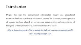
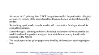
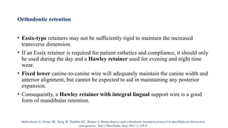
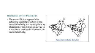
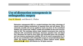
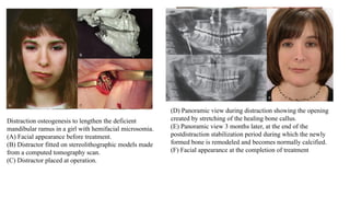
Distraction osteogenesis is a surgical technique used to induce new bone formation by gradually separating osteotomized bone segments, particularly beneficial in craniofacial reconstruction. The document elaborates on the history, principles, mechanisms, and implications of distraction osteogenesis, as well as its effects on both bone and surrounding soft tissues. It covers the procedure phases, classifications, and advancements in techniques, highlighting its significance in addressing congenital and acquired craniofacial anomalies.


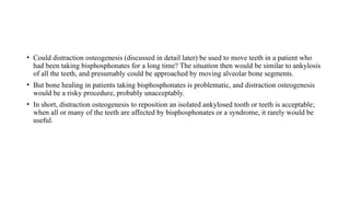
![Research and advances
Automated continuous DO
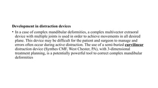
• Currently available distraction devices are patient and surgeon dependent. The
patient must adjust the manual control two or more times daily, often over long
periods.
Hariri F, Yoong Chin S, Rengarajoo J, Chao Foo Q, Nur Nabihah Zainul Abidin S, Fadhli Ahmad Badruddin A. Distraction Osteogenesis in
Oral and Craniomaxillofacial Reconstructive Surgery [Internet]. Osteogenesis and Bone Regeneration. IntechOpen; 2019.](https://image.slidesharecdn.com/distractionosteogenesis-241219123140-a9305f3e/85/Distraction-Osteogenesis-orthodontics-pptx-257-320.jpg)
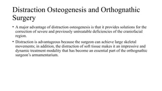
![• Because non-compliance and device failure are the leading causes of treatment
failure, the patient requires numerous clinical visits to ensure proper distractor
activation.
• Considering these drawbacks, many research groups are working to design novel
distraction devices that expand automatically and continuously. An automated
mechanism would eliminate the need for patient compliance and decrease the
frequency of post-operative visits for patient supervision.
• At the moment, the types of these devices are classified into three categories
based on the method of power: hydraulic, motor-driven and spring-mediated
Hariri F, Yoong Chin S, Rengarajoo J, Chao Foo Q, Nur Nabihah Zainul Abidin S, Fadhli Ahmad Badruddin A. Distraction Osteogenesis in
Oral and Craniomaxillofacial Reconstructive Surgery [Internet]. Osteogenesis and Bone Regeneration. IntechOpen; 2019.](https://image.slidesharecdn.com/distractionosteogenesis-241219123140-a9305f3e/85/Distraction-Osteogenesis-orthodontics-pptx-258-320.jpg)