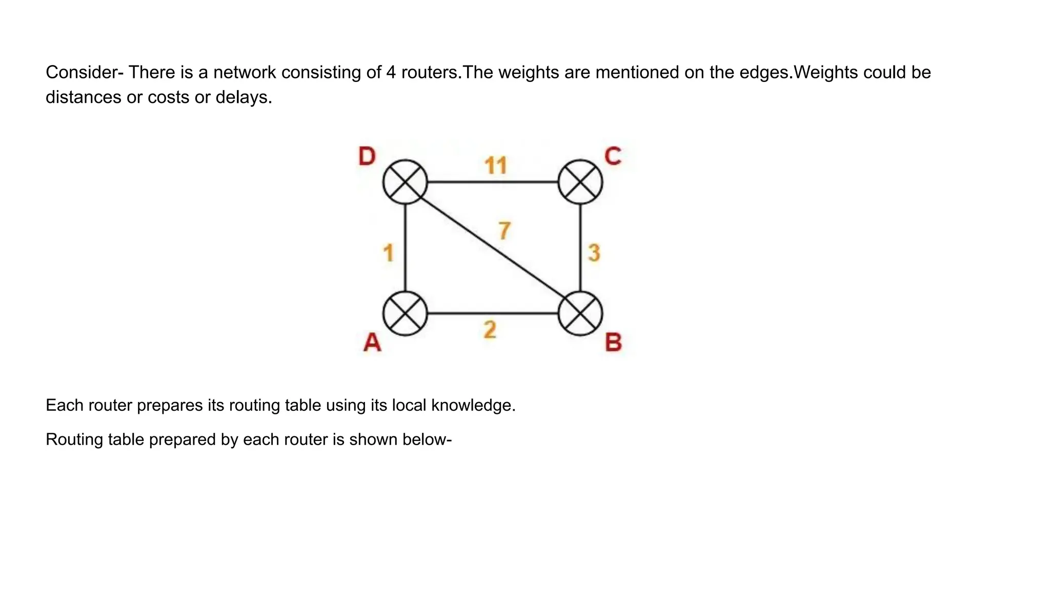
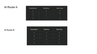
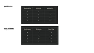
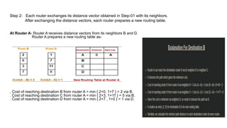
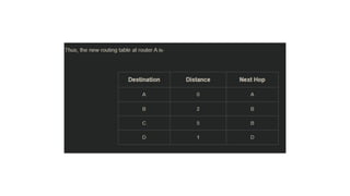
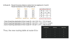
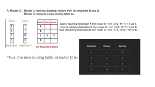
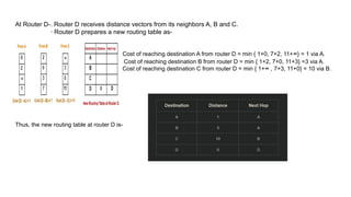
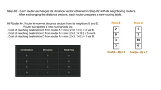
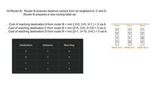
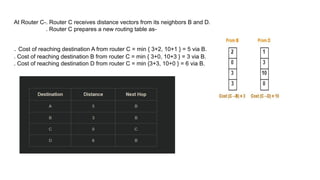
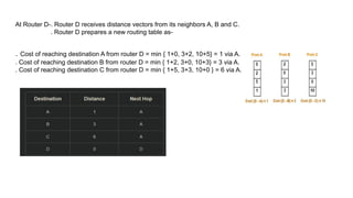
Consider- There is a network consisting of 4 routers.The weights are mentioned on the edges.Weights could be
distances or costs or delays.
Each router prepares its routing table using its local knowledge.
Routing table prepared by each router is shown below-
At Router A
At Router B
At Router C-
At Router D-
Step 2: Each router exchanges its distance vector obtained in Step-01 with its neighbors.
After exchanging the distance vectors, each router prepares a new routing table.
At Router A- Router A receives distance vectors from its neighbors B and D.
Router A prepares a new routing table as-
. Cost of reaching destination B from router A = min { 2+0, 1+7 } = 2 via B.
. Cost of reaching destination C from router A = min { 2+3, 1+11 } = 5 via B.
. Cost of reaching destination D from router A = min { 2+7 , 1+0 } = 1 via D.
At Router B- Router B receives distance vectors from its neighbors A, C and D.
Router B prepares a new routing table as-
. Cost of reaching destination A from router B = min { 2+0, 3+∞ , 7+1} =2 via A.
. Cost of reaching destination C from router B = min { 2+∞ , 3+0, 7+11 } = 3 via C.
. Cost of reaching destination D from router B = min {2+1, 3+11 , 7+0} =3 via A.
Thus, the new routing table at router B is-
At Router C- . Router C receives distance vectors from its neighbors B and D.
. Router C prepares a new routing table as-
Cost of reaching destination A from router C = min { 3+2, 11+1 } = 5 via B.
Cost of reaching destination B from router C = min { 3+0, 11+7} = 3 via B.
Cost of reaching destination D from router C = min { 3+7, 11+0} = 10 via B.
Thus, the new routing table at router C is-
At Router D-. Router D receives distance vectors from its neighbors A, B and C.
· Router D prepares a new routing table as-
Cost of reaching destination A from router D = min { 1+0, 7+2, 11+∞} = 1 via A.
Cost of reaching destination B from router D = min { 1+2, 7+0, 11+3} =3 via A.
Cost of reaching destination C from router D = min { 1+∞ , 7+3, 11+0} = 10 via B.
Thus, the new routing table at router D is-
Step-03:. Each router exchanges its distance vector obtained in Step-02 with its neighboring routers.
. After exchanging the distance vectors, each router prepares a new routing table.
At Router A-. Router A receives distance vectors from its neighbors B and D.
Router A prepares a new routing table as-
. Cost of reaching destination B from router A = min { 2+0, 1+3 } = 2 via B.
. Cost of reaching destination C from router A = min { 2+3, 1+10 } = 5 via B.
. Cost of reaching destination D from router A = min { 2+3, 1+0 } = 1 via D.
At Router B-. Router B receives distance vectors from its neighbors A, C and D.
. Router B prepares a new routing table as-
. Cost of reaching destination A from router B = min { 2+0, 3+5, 3+1 } = 2 via A.
. Cost of reaching destination C from router B = min {2+5, 3+0, 3+10} = 3 via C.
. Cost of reaching destination D from router B = min {2+1, 3+10, 3+0 } = 3 via A.
At Router C-. Router C receives distance vectors from its neighbors B and D.
. Router C prepares a new routing table as-
. Cost of reaching destination A from router C = min { 3+2, 10+1 } = 5 via B.
. Cost of reaching destination B from router C = min { 3+0, 10+3 } = 3 via B.
. Cost of reaching destination D from router C = min {3+3, 10+0 } = 6 via B.
At Router D-. Router D receives distance vectors from its neighbors A, B and C.
. Router D prepares a new routing table as-
. Cost of reaching destination A from router D = min { 1+0, 3+2, 10+5} = 1 via A.
. Cost of reaching destination B from router D = min { 1+2, 3+0, 10+3} = 3 via A.
. Cost of reaching destination C from router D = min { 1+5, 3+3, 10+0 } = 6 via A.
Identifying Unused Links-
After routing tables converge (becomes stable),
. Some of the links connecting the routers may never be used.
. In the above example, we can identify the unused links as-
We have-
. The value of next hop in the final routing table of router A suggests that only edges AB and AD are used.
. The value of next hop in the final routing table of router B suggests that only edges BA and BC are used.
. The value of next hop in the final routing table of router C suggests that only edge CB is used.
. The value of next hop in the final routing table of router D suggests that only edge DA is used.
Thus, edges BD and CD are never used.

distancevectorroutingandalgorithmcomputernetworks

  • 1.
    Consider- There isa network consisting of 4 routers.The weights are mentioned on the edges.Weights could be distances or costs or delays. Each router prepares its routing table using its local knowledge. Routing table prepared by each router is shown below-
  • 2.
  • 3.
    At Router C- AtRouter D-
  • 4.
    Step 2: Eachrouter exchanges its distance vector obtained in Step-01 with its neighbors. After exchanging the distance vectors, each router prepares a new routing table. At Router A- Router A receives distance vectors from its neighbors B and D. Router A prepares a new routing table as- . Cost of reaching destination B from router A = min { 2+0, 1+7 } = 2 via B. . Cost of reaching destination C from router A = min { 2+3, 1+11 } = 5 via B. . Cost of reaching destination D from router A = min { 2+7 , 1+0 } = 1 via D.
  • 6.
    At Router B-Router B receives distance vectors from its neighbors A, C and D. Router B prepares a new routing table as- . Cost of reaching destination A from router B = min { 2+0, 3+∞ , 7+1} =2 via A. . Cost of reaching destination C from router B = min { 2+∞ , 3+0, 7+11 } = 3 via C. . Cost of reaching destination D from router B = min {2+1, 3+11 , 7+0} =3 via A. Thus, the new routing table at router B is-
  • 7.
    At Router C-. Router C receives distance vectors from its neighbors B and D. . Router C prepares a new routing table as- Cost of reaching destination A from router C = min { 3+2, 11+1 } = 5 via B. Cost of reaching destination B from router C = min { 3+0, 11+7} = 3 via B. Cost of reaching destination D from router C = min { 3+7, 11+0} = 10 via B. Thus, the new routing table at router C is-
  • 8.
    At Router D-.Router D receives distance vectors from its neighbors A, B and C. · Router D prepares a new routing table as- Cost of reaching destination A from router D = min { 1+0, 7+2, 11+∞} = 1 via A. Cost of reaching destination B from router D = min { 1+2, 7+0, 11+3} =3 via A. Cost of reaching destination C from router D = min { 1+∞ , 7+3, 11+0} = 10 via B. Thus, the new routing table at router D is-
  • 9.
    Step-03:. Each routerexchanges its distance vector obtained in Step-02 with its neighboring routers. . After exchanging the distance vectors, each router prepares a new routing table. At Router A-. Router A receives distance vectors from its neighbors B and D. Router A prepares a new routing table as- . Cost of reaching destination B from router A = min { 2+0, 1+3 } = 2 via B. . Cost of reaching destination C from router A = min { 2+3, 1+10 } = 5 via B. . Cost of reaching destination D from router A = min { 2+3, 1+0 } = 1 via D.
  • 10.
    At Router B-.Router B receives distance vectors from its neighbors A, C and D. . Router B prepares a new routing table as- . Cost of reaching destination A from router B = min { 2+0, 3+5, 3+1 } = 2 via A. . Cost of reaching destination C from router B = min {2+5, 3+0, 3+10} = 3 via C. . Cost of reaching destination D from router B = min {2+1, 3+10, 3+0 } = 3 via A.
  • 11.
    At Router C-.Router C receives distance vectors from its neighbors B and D. . Router C prepares a new routing table as- . Cost of reaching destination A from router C = min { 3+2, 10+1 } = 5 via B. . Cost of reaching destination B from router C = min { 3+0, 10+3 } = 3 via B. . Cost of reaching destination D from router C = min {3+3, 10+0 } = 6 via B.
  • 12.
    At Router D-.Router D receives distance vectors from its neighbors A, B and C. . Router D prepares a new routing table as- . Cost of reaching destination A from router D = min { 1+0, 3+2, 10+5} = 1 via A. . Cost of reaching destination B from router D = min { 1+2, 3+0, 10+3} = 3 via A. . Cost of reaching destination C from router D = min { 1+5, 3+3, 10+0 } = 6 via A.
  • 13.
    Identifying Unused Links- Afterrouting tables converge (becomes stable), . Some of the links connecting the routers may never be used. . In the above example, we can identify the unused links as- We have- . The value of next hop in the final routing table of router A suggests that only edges AB and AD are used. . The value of next hop in the final routing table of router B suggests that only edges BA and BC are used. . The value of next hop in the final routing table of router C suggests that only edge CB is used. . The value of next hop in the final routing table of router D suggests that only edge DA is used. Thus, edges BD and CD are never used.