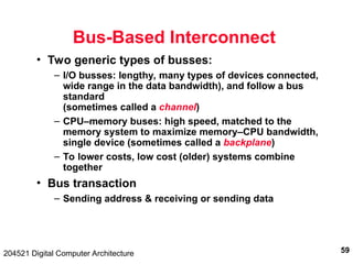
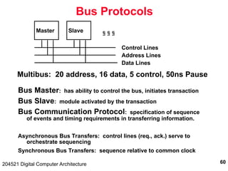
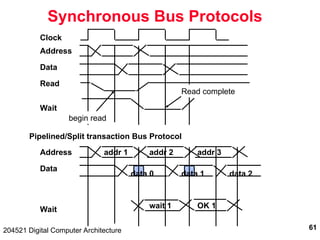
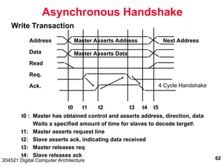
The document discusses digital computer architecture, focusing on input/output systems, buses, and their various types, including processor-memory and I/O buses. It highlights the advantages and disadvantages of bus systems, describes bus transaction dynamics, and addresses bus arbitration schemes. Additionally, it touches on modern integration concepts like the system-on-a-chip and the open core protocol for efficient communication in complex systems.
![43
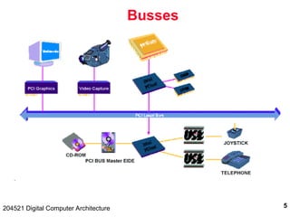
204521 Digital Computer Architecture
Basic OCP
Master
MCmd [3]
MAddr [N]
MData [N]
SResp [3]
SData [N]
Clk
SCmdAccept
Read:
Command, Address
Command Accept
Response, Data
Write (posted):
Command, Address,
Data
MCmd, MAddr
SCmdAccept
SResp, SData
MCmd, Maddr, MData
SCmdAccept
Slave](https://image.slidesharecdn.com/io2001-1-241220154832-1ef505ab/85/Digital-computer-architecture-issues-in-IO-43-320.jpg)


![Attack surfaces and attack tress[inform]](https://cdn.slidesharecdn.com/ss_thumbnails/lecture03-260108015941-a4dee53b-thumbnail.jpg?width=640&height=640&fit=bounds)


