Download to read offline


![References
[Bobda07] C. Bobda, “Introduction to Reconfigurable
Computing: Architectures, Algorithms and
Applications,” Springer, 2007.
26](https://image.slidesharecdn.com/061designflow-120815015235-phpapp02/85/design_flow-26-320.jpg)

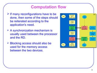
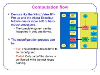
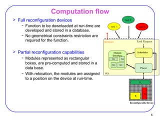
The document discusses computation flow for reconfigurable systems. It covers several key points: 1) Computation flow involves both run-time and compile-time iterations for some applications. 2) Synchronization and blocking access are usually used between the processor and reconfigurable device for memory access. 3) Full and partial reconfiguration approaches involve either fully or partially reconfiguring the FPGA device while it continues running other tasks. Managing computation flow and reconfiguration presents challenges around fragmentation and communication between new and old tasks.