Download to read offline


![8
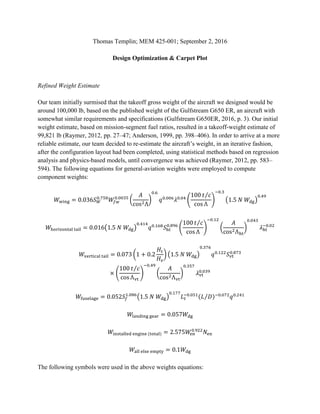
Calculate Wing Loading
WS_stall = (1/2*rho_SL*v_stall^2*CL_max)/.97;
WS_cruise = q_cruise*sqrt(C_D0/(3*K));
WS_loiter = q_loiter*sqrt(C_D0/K);
WS = min([WS_stall,WS_cruise, WS_loiter]);
% K = (1/2*rho_cruise*v_cruise^2/WS)^2*C_D0/3;
% AR = 1/(pi*e*K);
K = 1/(pi*e*AR);
CD = C_D0+K*CL_max^2;
CL_max_to_CD = CL_max/CD;
Calculate Thrust to Weight Ratio
v_climb = sqrt(2/rho_cruise*sqrt(K/C_D0)*WS);
TW_climb = (RC/v_climb + 2*sqrt(K*C_D0))*.97;
TW_takeoff = WS/(TOP*1*CL_max/1.21);
TW = max([TW_takeoff, TW_climb, TW_climb]);
Estimate weight
f_cruise = (1 - c_t*R/2*(rho_cruise*S/2/W_midcruise)^.5*4/3*(3*K*C_D0^3)^.25)^2;
f_loiter = exp(-c_t*E*2*sqrt(K*C_D0));
f_f = 1.06*(1 - .97*.985*f_loiter*f_cruise*.995);
%W_fuel = f_f*W_midcruise;
W_fuel = 40000;
S = W_midcruise/(WS);
b = sqrt(AR*S);
c_avg = S/b; %chord length
taper_tail = 0.5;
% Refined weight estimate - correlations from Raymer chapter 15
S_tailH = 0.7*c_avg*S/(L_plane - x_w); % 0.7 recommended from Raymer
S_tailV = 0.04*b*S/(L_plane - x_w); % 0.04 recommended from Raymer
W_wings = .036*S^.758*W_fuel^.0035*(AR/cosd(sweep)^2)^.6* ...
q_cruise^.006*taper^.04*(100*.13/cosd(sweep))^-.3*(1.5*N*W_midcruise)^0.49;
W_tailH = .016*(1.5*N*W_midcruise)^.414*q_cruise^.168*S_tailH^.896*(100*t_tail/...
cos(sweep))^-.12*(AR/cosd(sweep)^2)^.043*taper_tail^-.02;
W_tailV = .073*(1.5*N*W_midcruise)^.376*q_cruise^.122*S_tailV^.873*(100*t_tail/...
cos(sweep))^-.49*(AR/cosd(sweep)^2)^.357*taper_tail^.039;
W_fuse = .052*SA_fuse^1.086*(1.5*N*W_midcruise)^0.177*L_tail^-.051* ...
(1/sqrt(4*K*C_D0))^-0.072*q_cruise^.241;
W_gear = 0.057*W_midcruise;
W_engines = 2.575*2*W_engine^0.922;
W_etc = 0.1*W_midcruise;
W_empty = W_wings+W_tailH+W_tailV+W_fuse+W_gear+W_engines+W_etc;
W_0 = W_fuel + W_payload + W_empty;
plane_weights(i) = W_0;](https://image.slidesharecdn.com/designoptimizationcarpetplot-200324184631/85/Design-Optimization-and-Carpet-Plot-8-320.jpg)

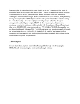
The document discusses the design optimization of an aircraft, initially estimating a takeoff gross weight of around 100,000 lb, refined to 76,068 lb using iterative statistical methods. The optimization process involved adjusting wing loading and thrust-to-weight ratios through a sizing matrix and carpet plot, ultimately identifying a minimum weight of 74,500 lb while meeting design requirements. Engine selection was critical to achieving the desired ratios, impacting performance and safety, with further sophisticated methods suggested for improved weight estimation.