The document summarizes the design process for a business jet capable of carrying 6 passengers up to 1500nm. Calculations were done to determine the required wing design based on the jet's weight and performance parameters. A transonic airfoil was selected, and calculations determined the wing should have an aspect ratio of 7 and wingspan of 27.487m. CFD analysis found the lift force was close to calculations but drag force was much higher, likely due to difficulty calculating drag by hand. The rest of the aircraft was designed around the selected wing.
Developing a Programme for Engine Design Calculations of a Commercial AirlinerIJMER
This project leads to a path of understanding the necessary fundamental calculations that
need to be done during an engine design of a commercial airliner. These calculations are hand based
calculations that are done based on the parameters of the airframe data provided by the airline
manufacturers. These calculations are a little tedious and require a paper and a pen to carry out the
procedures. This project will enable the following outcomes for the students: providing a fundamental
understanding of the aircraft engine design, more from the grounds up approach and an automated way
(program) of doing the above, enabling faster iterations and making it easy to achieve the required
parameters for designing an engine
Design Analysis Of Uav (Unmanned Air Vehicle) Using NACA 0012 Aerofoil ProfileDr. Bhuiyan S. M. Ebna Hai
This research work is concerned with the application of conceptual design of Unmanned Air Vehicle (UAV). UAV is used for surveillance and reconnaissance to serve for the defense as well as national security and intelligence purpose. Here NACA 0012 aerofoil profile is used to design UAV by using CFD (Computational Fluid Dynamics) software. The aim of this research is to investigate the flow patterns and determine the aerodynamic characteristics of NACA 0012 profile by varying the angle of attack and Reynolds Number numerically. The research is carried out with symmetric aerofoil with the chord length of 0.1m. The research work explained different aerodynamic characteristics like lift force and drag force, lift and drag coefficient, pressure distribution over aerofoil etc.
The flow across an airfoil is studied for different angle of attack. The CFD analysis results are documented and studied for different angle of attack using fluent & gambit.
Tutorial VSP Conference 2013, San Luis Obispo, CAHersh Amin
Vehicle Sketch Pad Structure Analysis Module (VSP SAM, http://vspsam.ae.utexas.edu/) tutorial presentation at the 2nd annual VSP (http://openvsp.org/) workshop held in San Luis Obispo, CA from Aug 7-9, 2013.
Tutorial VSP Conference 2013, San Luis Obispo, CAHersh Amin
Vehicle Sketch Pad Structure Analysis Module (VSP SAM, http://vspsam.ae.utexas.edu/) tutorial presentation at the 2nd annual VSP (http://openvsp.org/) workshop held in San Luis Obispo, CA from Aug 7-9, 2013.
This was my final year project thesis, based on the results from NASA Langley Research Centre’s work on the PRANDTL-D project which was into minimizing the induced drag of a wing body along with elimination of adverse yaw.
• Created a conceptual aircraft that can use wing in ground effect to fly at low altitude to achieve fuel efficiency and high payload carrying capacity.
Strategic design of aircraft wings have evolved over time for maximum fuel efficiency. One of such ideas involves winglet which has been known
to reduce turbulence at the tip of the wings. This study intends to investigate the
differences in drag and lift forces generated at aeroplane wings with and without winglet at cruising speed using FEM. Simulations were performed in the
SST turbulence model of CFD and the results are compared to that of the experimental and theoretical models. The simulation showed that the lift increased
by 26.0% and the drag decreased by 74.6% for the winglet at cruising speed.
International Journal of Engineering Research and DevelopmentIJERD Editor
Electrical, Electronics and Computer Engineering,
Information Engineering and Technology,
Mechanical, Industrial and Manufacturing Engineering,
Automation and Mechatronics Engineering,
Material and Chemical Engineering,
Civil and Architecture Engineering,
Biotechnology and Bio Engineering,
Environmental Engineering,
Petroleum and Mining Engineering,
Marine and Agriculture engineering,
Aerospace Engineering.
Fighter jet Swept back wing design and Analysis by using of Xflr5Mani5436
1.V-N DIAGRAM
2.Prepared an aircraft wing design for the proposed structure.
3.Selected geometry in the plane (wing area, aspect ratio, cords) and sweep, dihedral, twist angles.
4.Airfoil Aerodynamic characteristics
Design and Analysis of Solar Powered RC Aircrafttheijes
The International Journal of Engineering & Science is aimed at providing a platform for researchers, engineers, scientists, or educators to publish their original research results, to exchange new ideas, to disseminate information in innovative designs, engineering experiences and technological skills. It is also the Journal's objective to promote engineering and technology education. All papers submitted to the Journal will be blind peer-reviewed. Only original articles will be published.
1. Introduction
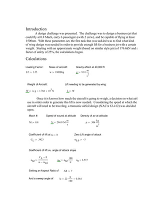
A design challenge was presented. The challenge was to design a business jet that
could fly at 0.8 Mach, carry 6 passengers (with 2 crew), and be capable of flying at least
1500nm. With these parameters set, the first task that was tackled was to find what kind
of wing design was needed in order to provide enough lift for a business jet with a certain
weight. Starting with an approximate weight (based on similar style jets) of 176.6kN and a
factor of safety of 25%, the calculations began.
Calculations
Loading Factor: Mass of aircraft: Gravity effect at 40,000 ft
LF 1.25 w 18000kg g 9.81
m
s
2
Weight of Aircraft: Lift needing to be generated by wing:
W w g 1.766 10
5
N L W
Once it is known how much the aircraft is going to weigh, a decision on what airf
use in order order to generate this lift is now needed. Considering the speed at which the
aircraft will need to be traveling, a transonic airfoil design (NACA 63-412) was decided
upon.
Mach #: Speed of sound at altitude Density of air at altitude:
M 0.8 V 294.9 M
m
s
ρ .304
kg
m
3
Coefficient of lift at α 0 Zero Lift angle of attack
CL .3423 αL0 3
Coefficient of lift vs. angle of attack slope
a0d
CL 0
α αL0
a0 a0d
180
π
a0 6.537
Setting an Aspect Ratio of AR 7
And a sweep angle of Λ 22
π
180
0.384
2. Kuchemann's Lift slope for swept wings
a
a0 cos Λ( )
1
a0 cos Λ( )
π AR
2
a0 cos Λ( )
π AR
4.617
ad a
π
180
0.081
Maximum Coefficient of lift for the angle of attack specified, with this geometry
CLmax ad α αL0 0.242
Rearranging the coefficient of lift equation to find the Plan form Area (S)
S
L LF
1
2
ρ V
2
CLmax
The Plan Form area (for both wings):
S 107.93 m
2
And rearranging the equation to find b, the wingspan can be found
b AR S 27.487 m
b1wing
b
2
13.743 m
A typical tip chord to root chord ratio is known
Ct 0.2 Cr Cr
Rearrange the area of a trapezoid using the above relation:
Cr
2 S
1.2 b
6.544 m
3. Again...
Ct 0.2Cr
Ct 1.309 m
Coefficient of Drag Reference Area for Drag calculations
CD .00562
DA
Cr .12 Ct .12
2
b1wing 6.476 m
2
Coefficient of Drag Induced
CDi
CLmax
2
π AR
2.657 10
3
Coefficient of Drag from Pressure
Total Coefficient of Drag
CDP .00110 CDT CD CDi CDP 9.377 10
3
Drag Force
D CDT ρ DA
V
2
2
513.737 N
Induced Angle of Attack Effective Angle of Attack
αi
CLmax
π AR
0.011 αeff α
180
π
αi 0.63
Now that a wing design has been decided on, a comparison of the hand
calculations versus the CFD will be done.
In order to make up for the induced angle of attack, an addition of 1 degrees
to the angle of attack was added to the CFD.
After running the CFD the lift and drag forces were extracted. A lift force of
approximately 93377N and a drag force of approximately 1944N were found (for one
wing). The maximum velocity over the wing was 309.4m/s. The percent error is 5.75%
for the lift force and 278% for the drag force. The lift force is very close, within a good
error percentage, but the drag force is very far away from the calculated value. The
4. difference, is probably due to the difficulty in calculating drag forces by hand. All valu
can be found in Table 1 located in the appendix.
Finally, the rest of the design of the aircraft was done. A tricycle style landing g
layout was used, and an empannage with 2 horizontal rear stabilizers, and a rudder set u
as shown in Figure 5, and capable of counteracting the moment about the center of grav
caused by the wings. Two Honeywell HTF7500E were selected for propulsion due to
high thrust and efficiency. Capable of approximately 6000lbf per engine, with a fuel ta
of 2,100, the business jet design is capable of over 2000nm, much higher than the range
specified for the project. The cabin was designed with the ability to house up to 7
passengers comfortably. With an internal height of approximately 2m, and an internal w
of approximately 2m as well, this is on the top end of comfort.
Conclusion
The design of the aircraft has taught a lot about computer based design and fluid
dynamics. The results of the CFD and the hand calculations were reasonable, outside o
the drag force, and were within a safe margin of error.