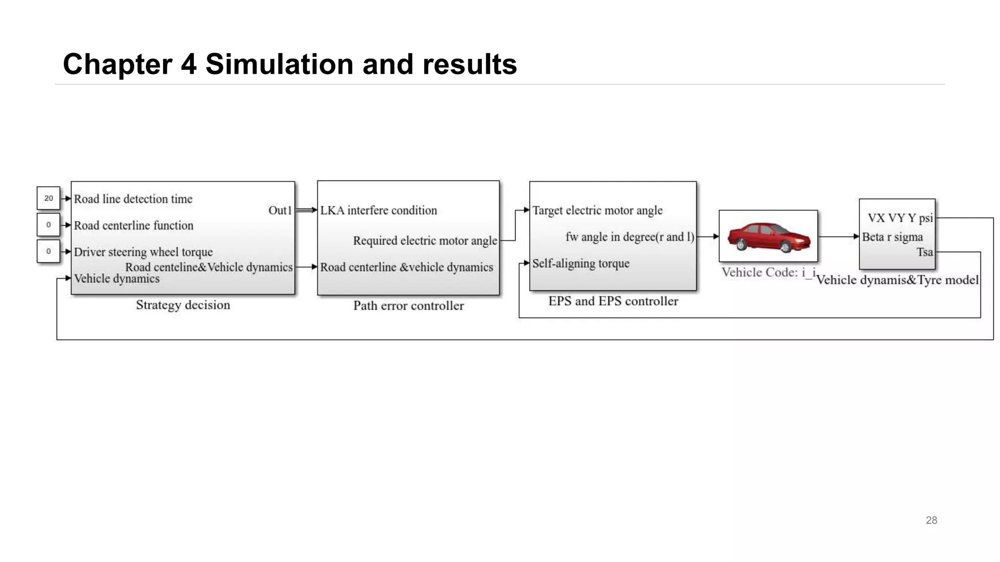
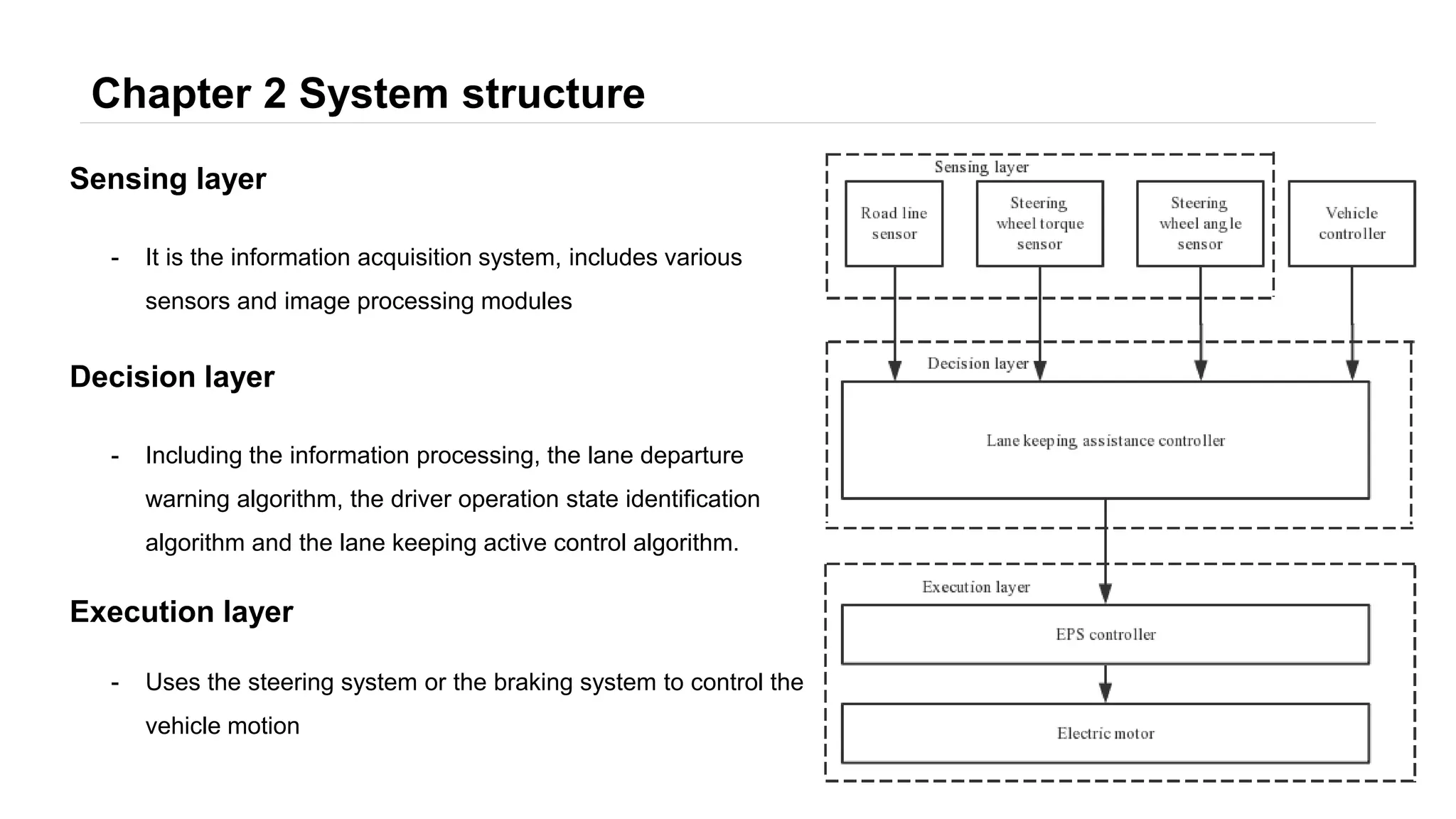
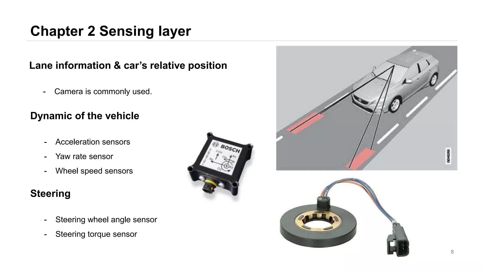
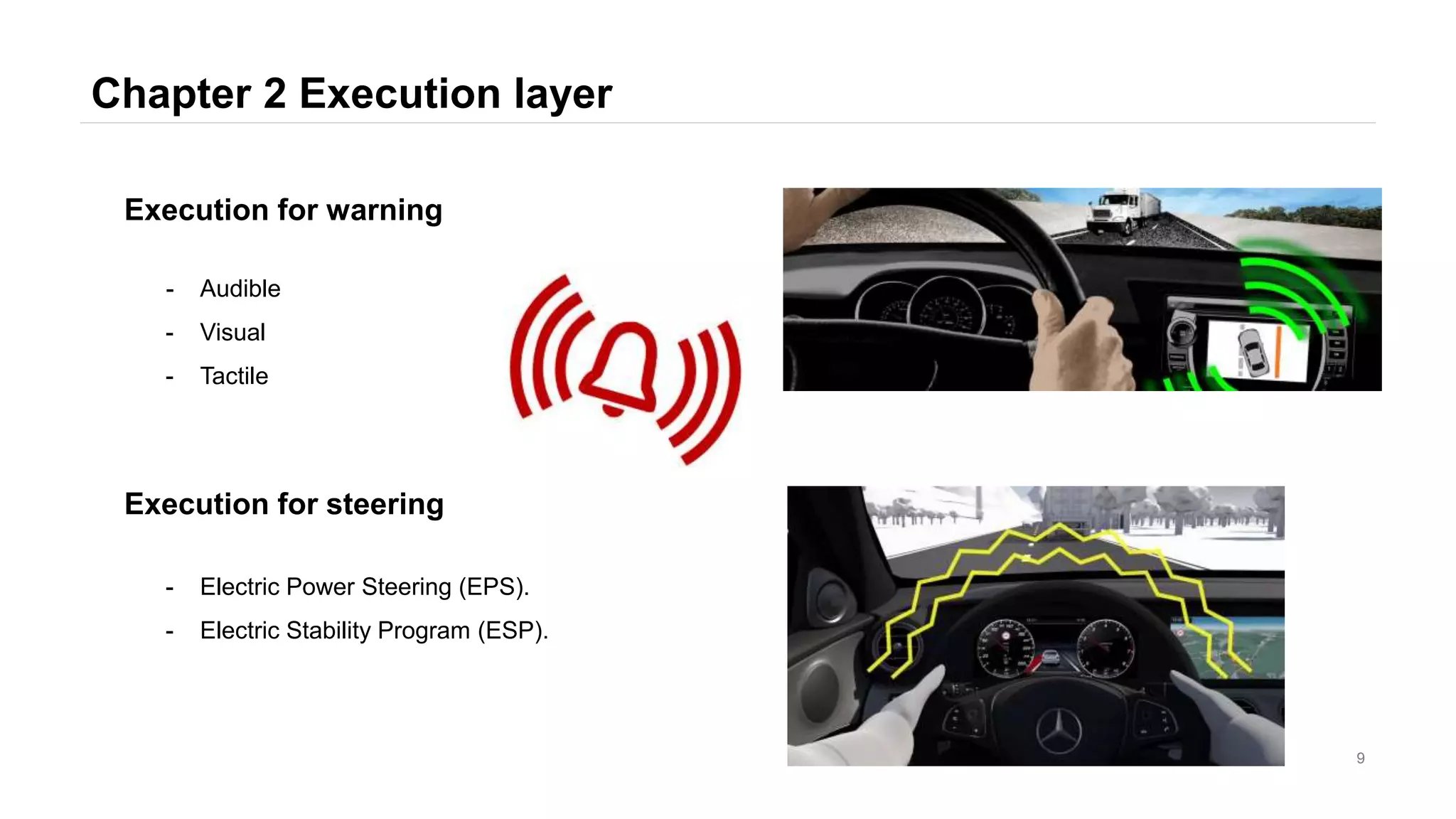
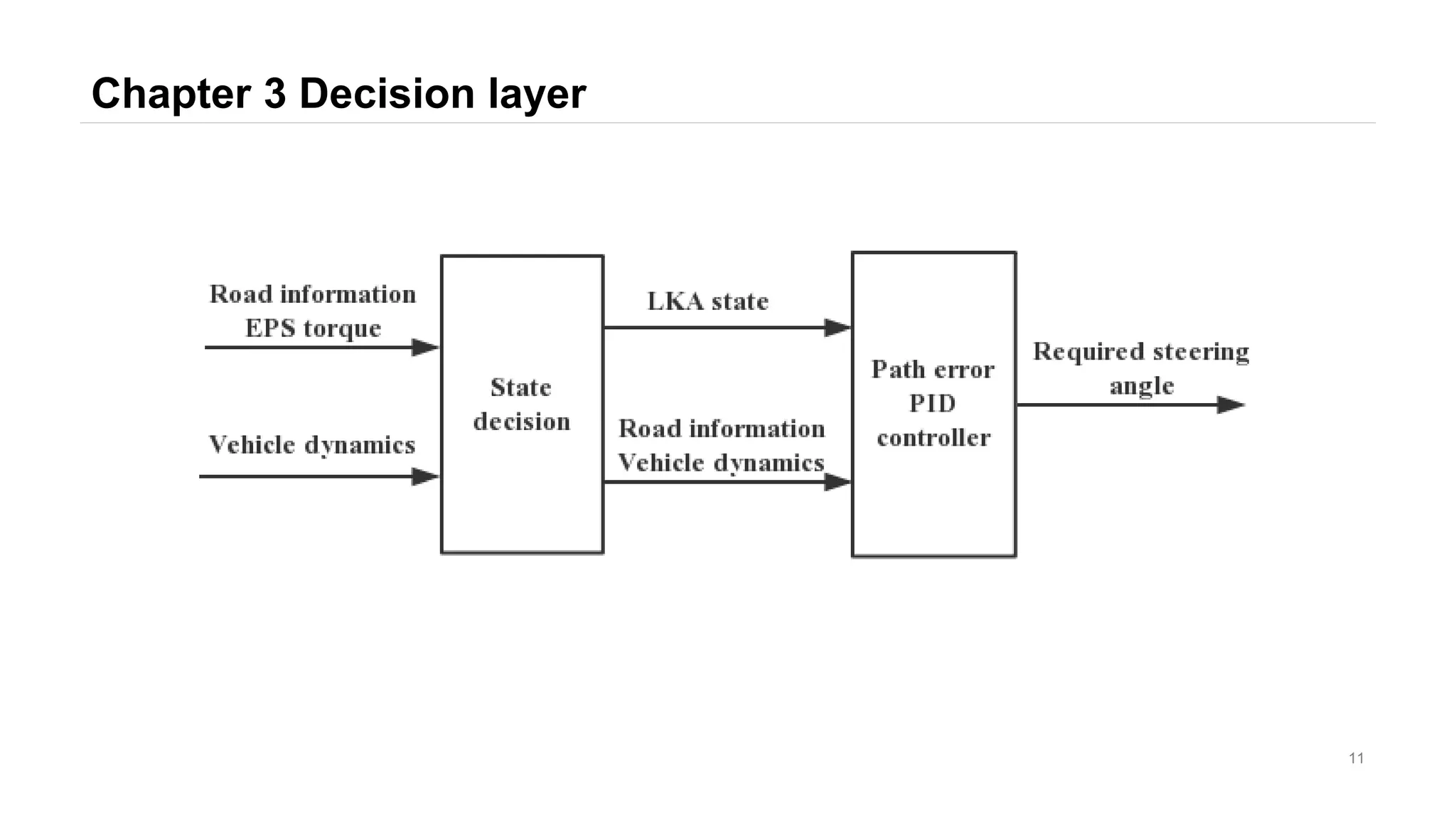
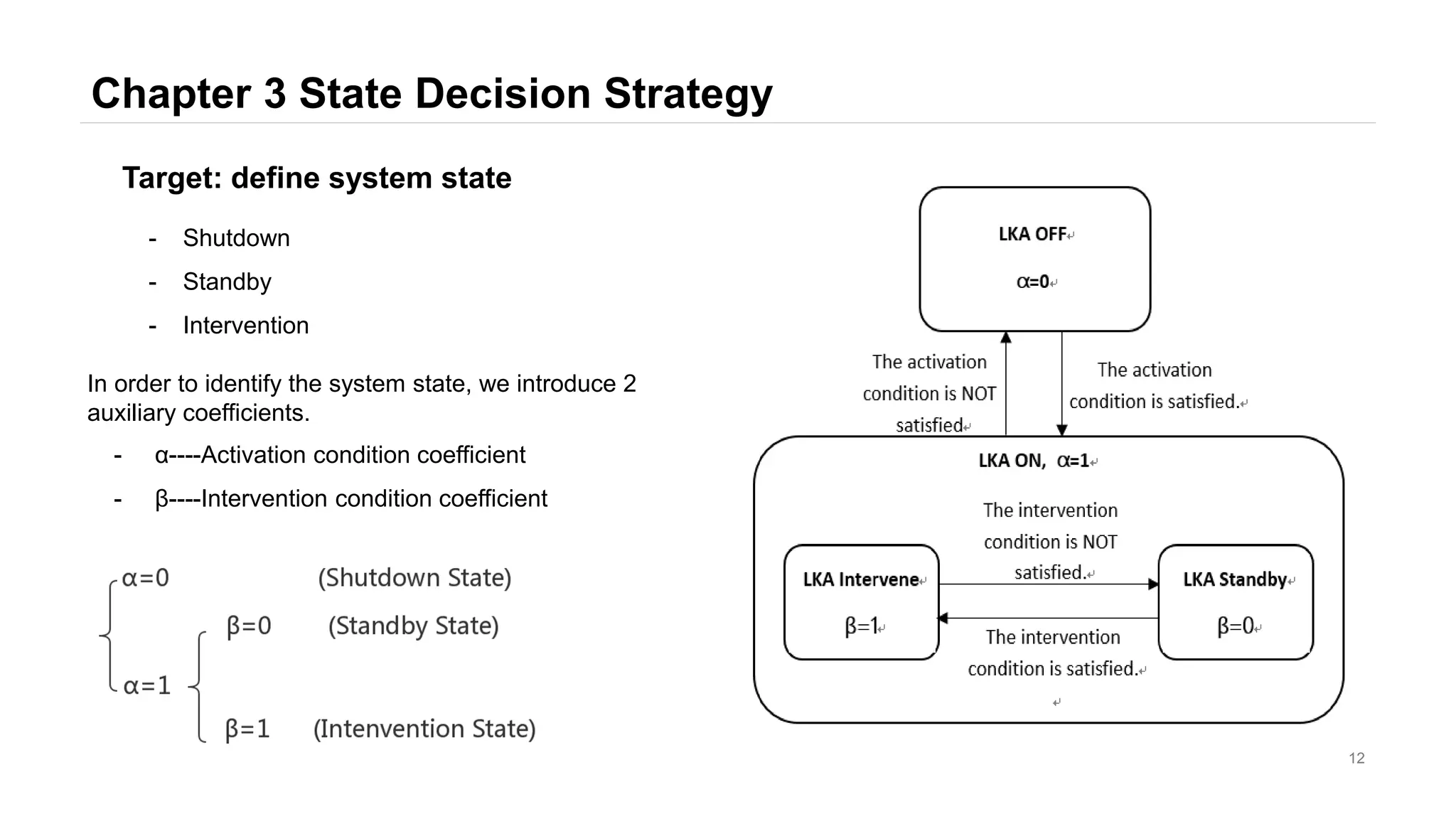
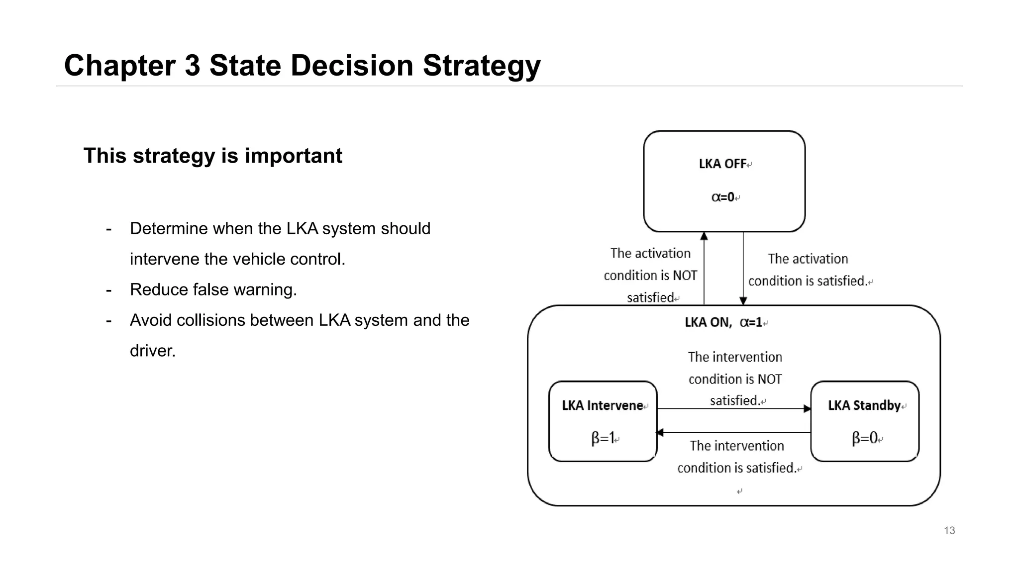
This document describes a lane keeping assist system. It includes three main parts: a sensing layer that uses sensors to acquire vehicle and lane information; a decision layer that processes the data and determines when warnings or interventions are needed; and an execution layer that provides warnings or controls the steering system. The decision layer uses state decision and path error control algorithms to determine when the system should activate, provide warnings, or intervene in vehicle control. The system is designed to keep the vehicle centered in its lane in a way that reduces false warnings and avoids conflicts with the driver. It is simulated and tested in CarSim software.
![Chapter 1 Introduction
3
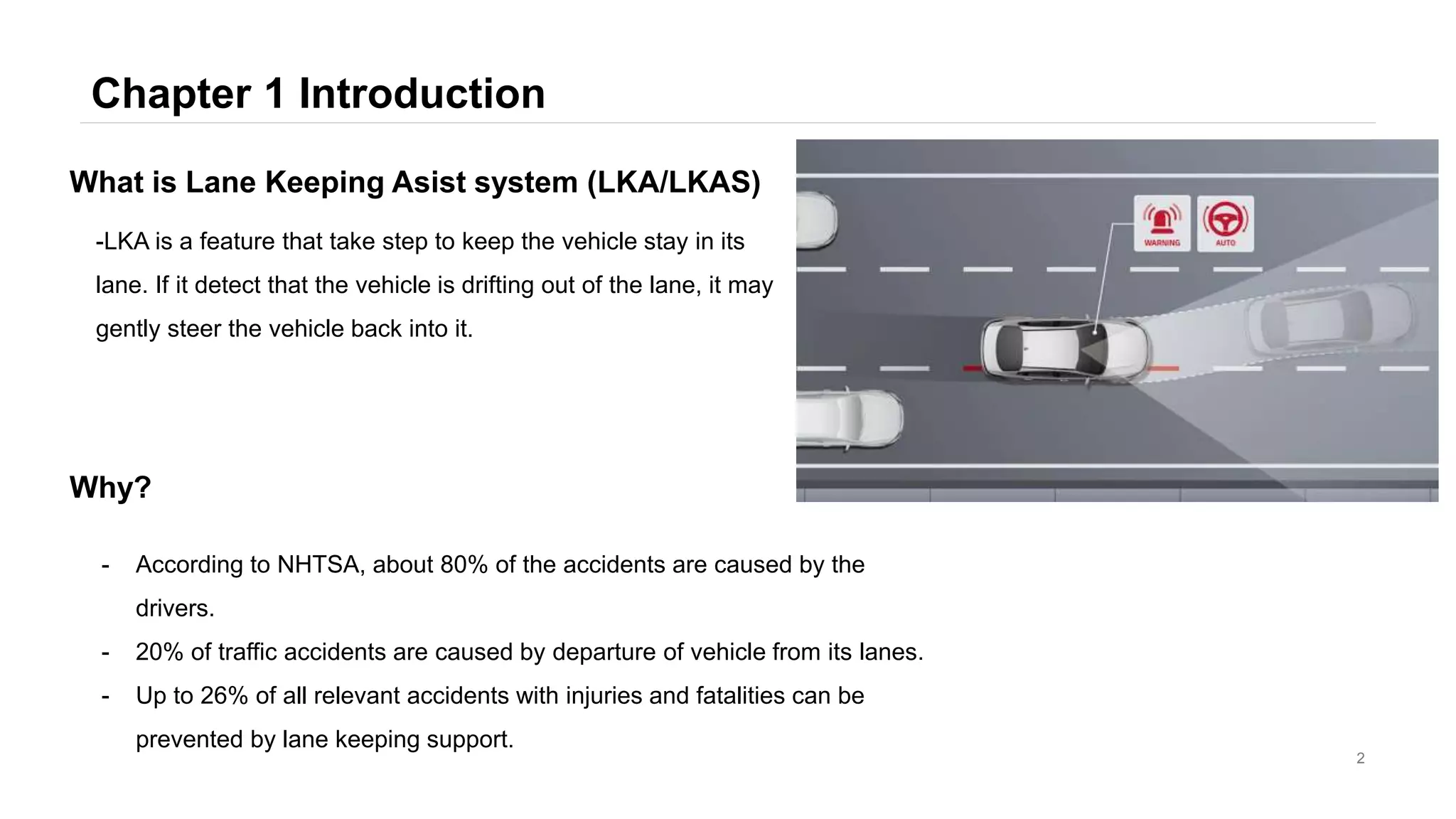
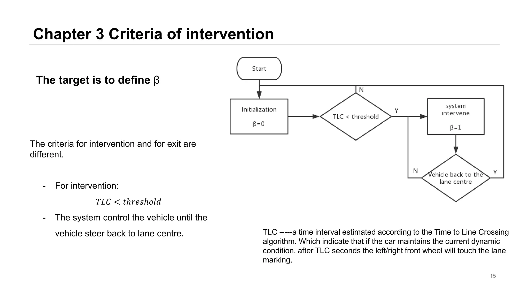
- The LKA system is a auxiliary function, not a autonomous
function. The driver should always touch the steering wheel.
Drivers with hands-off is a misuse.
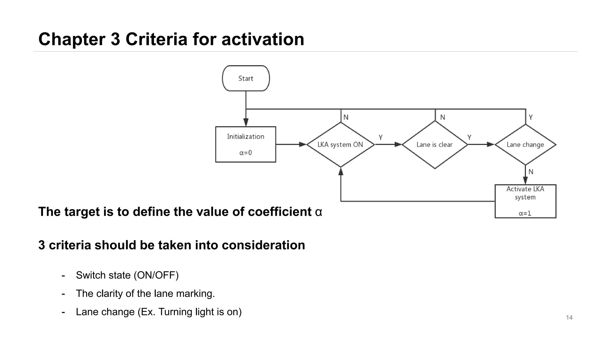
- The activation condition of LKA system is at least 60km/h. The
curvature should be at least 250m.
UN/ECE Regulations
[1] Regulation No 79 of the Economic Commission for Europe of the United Nations (UN/ECE)
— Uniform provisions concerning the approval of vehicles with regard to steering equipment
[2] Regulation No 130 of the Economic Commission for Europe of the United Nations (UN/ECE)
— Uniform provisions concerning the approval of motor vehicles with regard to the Lane Departure Warning System (LDWS).](https://image.slidesharecdn.com/waiyuntianlouadaslka-190228100035/75/Design-of-Lane-Keeping-Assist-3-2048.jpg)
![Reference
4
[1] Guo Hongqiang, Chen Hui, Chen Jiayu. Design of Lane-based Lane Maintenance System Based on EPS[J].
Automotive Technology, 2018(08): 33-38.
[2]Yu Lijiao. Design and experimental verification of lane-based auxiliary control algorithm based on EPS [D]. Jilin
University, 2016.
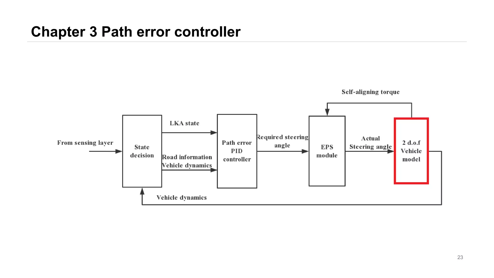
Structure of LKA control system
[1]Baharom M B, Hussain K, Day A J. Design of full electric power steering with enhanced performance over that of
hydraulic power-assisted steering[J]. Proceedings of the Institution of Mechanical Engineers Part D Journal of
Automobile Engineering, 2013, 227(3):390-399.
[2] Zhang Hailin. Lane keeping system based on electric steering [D]. Tsinghua University, 2012.
[3]Cheng Shuliang. Modeling and simulation analysis of electric power steering system [D]. Chongqing University,
2016
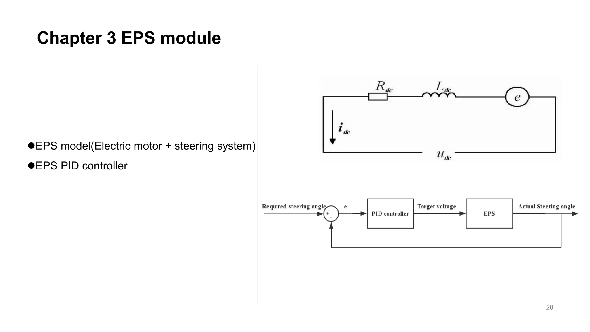
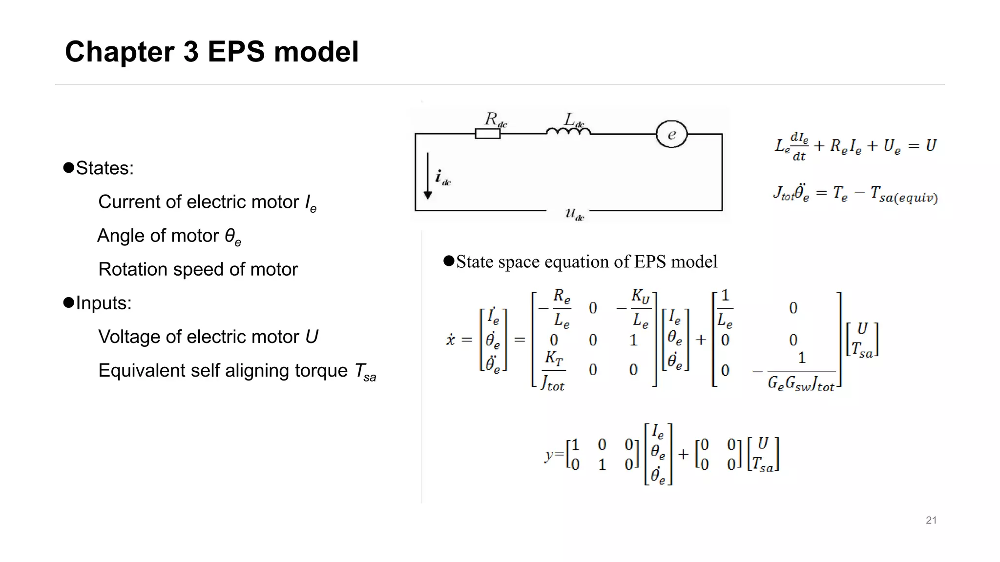
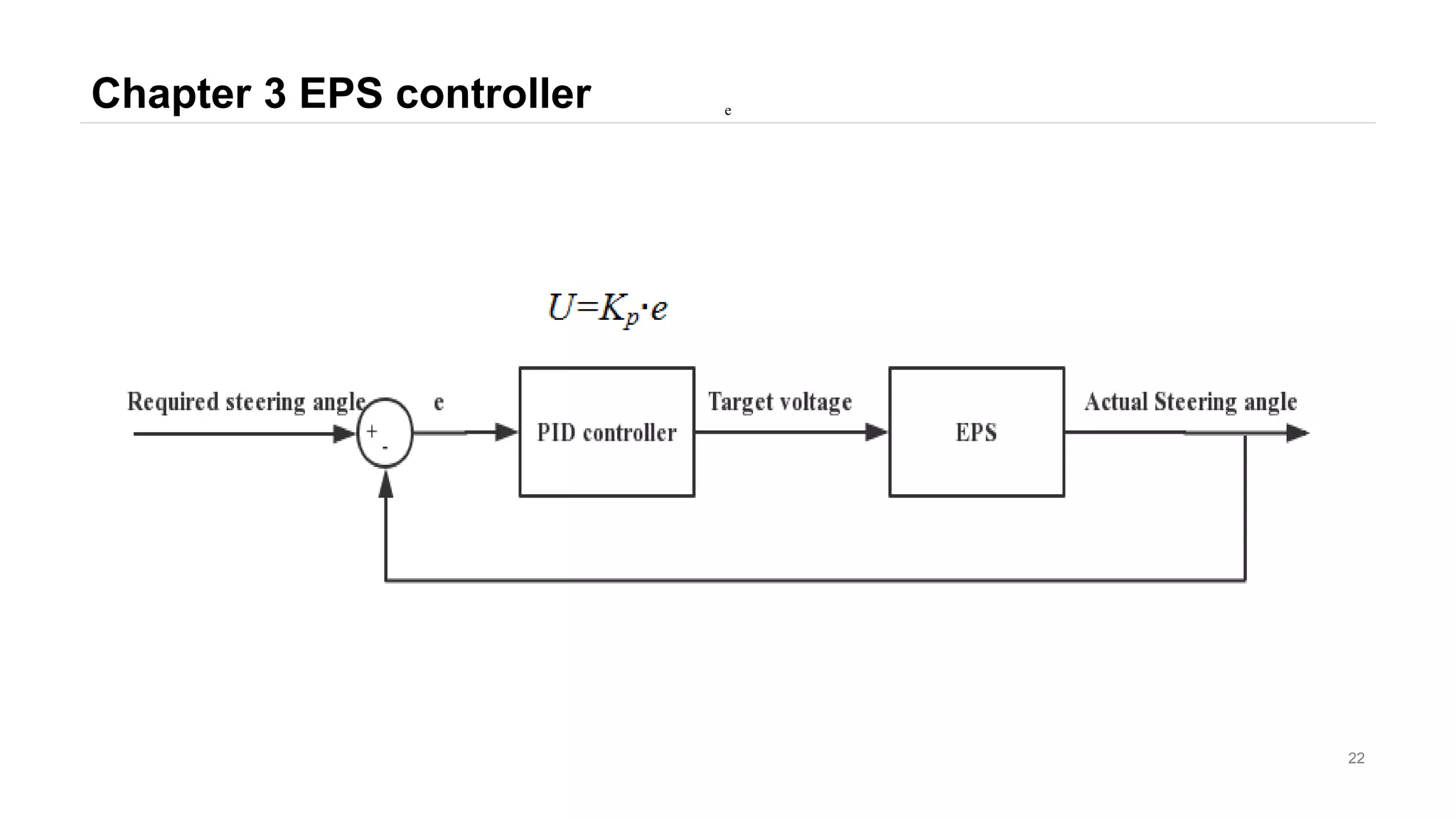
EPS model
[1]Prof. Nicola Amati. Chassis A notes. High speed cornering simplified approach
[2]Yu Lijiao. Design and experimental verification of lane-based auxiliary control algorithm based on EPS [D]. Jilin
University, 2016.
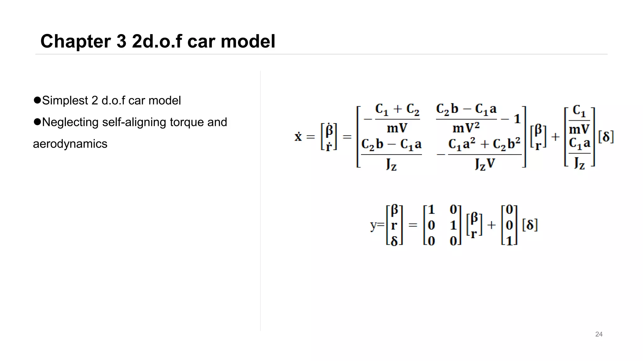
2 d.o.f. vehicle model](https://image.slidesharecdn.com/waiyuntianlouadaslka-190228100035/75/Design-of-Lane-Keeping-Assist-4-2048.jpg)
![Reference
5
[1] Carlo Novara. Automatic control. Lecture 21 Lane Keeping
[2] Zhang Hailin. Lane keeping system based on electric steering [D]. Tsinghua University, 2012.
Driver model
[1] Ziegler, J.G & Nichols, N. B. (1942). "Optimum settings for automatic controllers’’ Transactions of the ASME. 64:
759–768.
[2] Nyquist, H. (1932). "Regeneration Theory". Bell System Tech. J. USA: American Tel. & Tel. 11 (1): 126–147
Design of PID controller](https://image.slidesharecdn.com/waiyuntianlouadaslka-190228100035/75/Design-of-Lane-Keeping-Assist-5-2048.jpg)


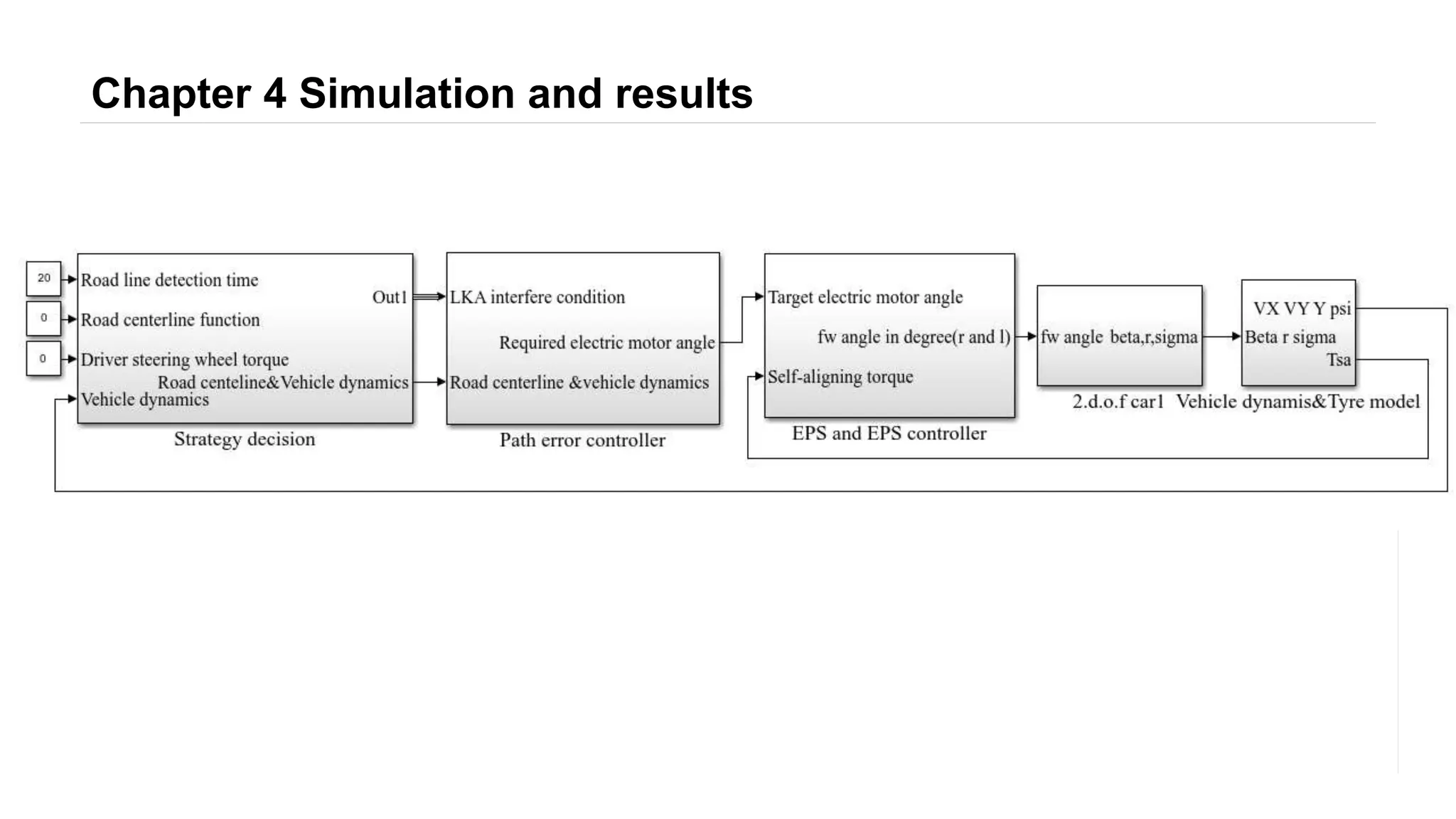
![Chapter 4 Simulation and results
27
V=60km/h
T ϵ [1,2]
Apply a steering
angle to the
steering wheel](https://image.slidesharecdn.com/waiyuntianlouadaslka-190228100035/75/Design-of-Lane-Keeping-Assist-27-2048.jpg)