Call Girls In Kishangarh Delhi ❤️8860477959 Good Looking Escorts In 24/7 Delh...
Design notes
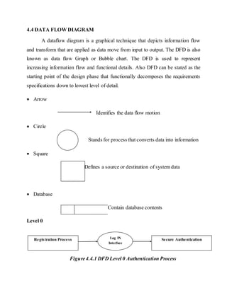
1. 4.4 DATA FLOW DIAGRAM
A dataflow diagram is a graphical technique that depicts information flow
and transform that are applied as data move from input to output. The DFD is also
known as data flow Graph or Bubble chart. The DFD is used to represent
increasing information flow and functional details. Also DFD can be stated as the
starting point of the design phase that functionally decomposes the requirements
specifications down to lowest level of detail.
Arrow
Identifies the data flow motion
Circle
Stands for process that converts data into information
Square
Defines a source or destination of system data
Database
Contain database contents
Level 0
Figure4.4.1 DFD Level 0 Authentication Process
Registration Process Log IN
Interface
Secure Authentication
2. Level 1
Stored in database
Figure4.4.2 DFD Level 1 Registration Process
Level2
Database
Valid
Valid
Valid
Figure4.4.3 DFD Level 2 Log In interface Process
Registration Process
YubiKey generation and
stored into the Device
User Password sends to registeredmobile
number and email address
Registration Successful
Log In Interface Insert YubiKey
OTP generation and send to
registeredmobile number and
Email Address
Enter Namely
Password
Authentication
Successful
Enter OTP
3. I/O FORM DESIGN
INPUT DESIGN
Input design is the link between information system and user. It comprises
the developing specification and procedures for data preparation and those steps
are necessary to put transaction data into usable form for processing data entry.
The activity of putting data into computer for processing can be achieved by
inspecting the computer to read data from a written or printed document or it can
occurby having people keying the data into the system.
Fig 5.2.1: Login Form
User or Customer should enter their Loginid and Password. If the loginid and
Password is valid then application ask user to plug YubiKey to the Computer,
and also the yubiKey is correct, application take user to the Output form.
4. OUTPUT DESIGN
Computer output is the most important and direct information source to
user. Output design involves designing necessary outputs in the forms of reports
that should be given to the users according to the requirements. Efficient
intelligible output design should improve the system’s relationship with the user
and help in decision making. Since the reports are directing referred by the
management for taking decisions and to draw conclusions they must be designed
with almost care and the details in the reports must be simple, descriptive and clear
to the user. So while designing output the following things are to be considered.
Fig 5.2.2: User Account Form
User can able to access their Bank account in the output form and update
information’s, change Profile picture, access Calculator, Currency Convertor
and so on.
5. DATABASE/DATASTRUCTUREDESIGN
The Database Data structure consists of data types that are available within
the database system and the method in which they are entering the various fields
with its ranges. Table list the most commonly used data structures with reference
server, Access, MYSQL.
5.4 TABLE
Fields Data Type Contraints
LoginID varchar(50) Null
BankAccountNumber nvarchar(MAX) Null
ATMCardNumber nvarchar(50) Null
CurrentBalance bigint Null
FixedDeposit nvarchar(50) Null
Table 5.4.1 Customer’s Bank AccountInformation’s Table
6. Table 5.4.2 Customer’s Information Table
Fields Data Type Constraints
LoginID varchar (50) Null
BankAccountNo nvarchar (50) Null
ATMCardNo nvarchar (50) Null
UserName varchar (max) Null
Password varchar (50) Null
Age int Null
Gender varchar (50) Null
Birthday varchar (50) Null
PhoneNumber bigint Null
ResidencePhoneNumber nvarchar (50) Null
EmailAddress varchar (50) Null
Country varchar (50) Null
State varchar (50) Null
City varchar (50) Null
Pincode nvarchar (50) Null
Image image Null
YubiKey varchar(max) Null
7. ARCHITECTURAL DESIGN
Fig 5.5.1 Architecture Design
For Use case DiagramReferthe link below and make something like the
examples
http://www.uml-diagrams.org/use-case-diagrams-examples.html